JP6149721B2 - ハイブリッド車両用ユニットの取付構造 - Google Patents
ハイブリッド車両用ユニットの取付構造 Download PDFInfo
- Publication number
- JP6149721B2 JP6149721B2 JP2013261874A JP2013261874A JP6149721B2 JP 6149721 B2 JP6149721 B2 JP 6149721B2 JP 2013261874 A JP2013261874 A JP 2013261874A JP 2013261874 A JP2013261874 A JP 2013261874A JP 6149721 B2 JP6149721 B2 JP 6149721B2
- Authority
- JP
- Japan
- Prior art keywords
- case
- vehicle
- boss
- mounting structure
- boss portion
- Prior art date
- Legal status (The legal status is an assumption and is not a legal conclusion. Google has not performed a legal analysis and makes no representation as to the accuracy of the status listed.)
- Active
Links
Images


Classifications
-
- Y—GENERAL TAGGING OF NEW TECHNOLOGICAL DEVELOPMENTS; GENERAL TAGGING OF CROSS-SECTIONAL TECHNOLOGIES SPANNING OVER SEVERAL SECTIONS OF THE IPC; TECHNICAL SUBJECTS COVERED BY FORMER USPC CROSS-REFERENCE ART COLLECTIONS [XRACs] AND DIGESTS
- Y02—TECHNOLOGIES OR APPLICATIONS FOR MITIGATION OR ADAPTATION AGAINST CLIMATE CHANGE
- Y02T—CLIMATE CHANGE MITIGATION TECHNOLOGIES RELATED TO TRANSPORTATION
- Y02T10/00—Road transport of goods or passengers
- Y02T10/60—Other road transportation technologies with climate change mitigation effect
- Y02T10/62—Hybrid vehicles
Landscapes
- Hybrid Electric Vehicles (AREA)
- Arrangement Or Mounting Of Propulsion Units For Vehicles (AREA)
Description
Claims (3)
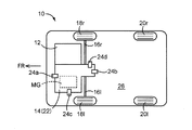
- 電動機を収容するケースから外側へボス部が一体に突き出され、該ボス部に取り付けられたマウントを介してボデーに懸架されるハイブリッド車両用ユニットにおいて、
車両前進方向を前方として、前記ボス部よりも前方側に、前記車両の前方衝突時の荷重が入力された場合に前記マウントが前記ケースに対して前記前方側へ移動することを許容する脆弱部を備えた
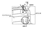
ことを特徴とする取付構造。 - 前記ケースは、該ケースから一体に突き出されたフランジ部において隣り合う部材に締結され、
前記ボス部は、前記フランジ部との間に前記脆弱部が介在することにより前記フランジ部と離隔させられている
請求項1に記載の取付構造。 - 前記ケースは、前記脆弱部よりも前記前方側に肉厚部を備えたものである
請求項1又は2に記載の取付構造。
Priority Applications (1)
| Application Number | Priority Date | Filing Date | Title |
|---|---|---|---|
| JP2013261874A JP6149721B2 (ja) | 2013-12-18 | 2013-12-18 | ハイブリッド車両用ユニットの取付構造 |
Applications Claiming Priority (1)
| Application Number | Priority Date | Filing Date | Title |
|---|---|---|---|
| JP2013261874A JP6149721B2 (ja) | 2013-12-18 | 2013-12-18 | ハイブリッド車両用ユニットの取付構造 |
Publications (2)
| Publication Number | Publication Date |
|---|---|
| JP2015116943A JP2015116943A (ja) | 2015-06-25 |
| JP6149721B2 true JP6149721B2 (ja) | 2017-06-21 |
Family
ID=53530069
Family Applications (1)
| Application Number | Title | Priority Date | Filing Date |
|---|---|---|---|
| JP2013261874A Active JP6149721B2 (ja) | 2013-12-18 | 2013-12-18 | ハイブリッド車両用ユニットの取付構造 |
Country Status (1)
| Country | Link |
|---|---|
| JP (1) | JP6149721B2 (ja) |
Family Cites Families (4)
| Publication number | Priority date | Publication date | Assignee | Title |
|---|---|---|---|---|
| JP4239478B2 (ja) * | 2002-05-17 | 2009-03-18 | アイシン・エィ・ダブリュ株式会社 | 変速機ケース |
| JP4059877B2 (ja) * | 2004-10-14 | 2008-03-12 | トヨタ自動車株式会社 | ハイブリッド駆動装置 |
| JP2011027245A (ja) * | 2009-07-29 | 2011-02-10 | Toyota Motor Corp | 駆動ユニット |
| JP2012183896A (ja) * | 2011-03-04 | 2012-09-27 | Honda Motor Co Ltd | 鞍乗り型車両 |
-
2013
- 2013-12-18 JP JP2013261874A patent/JP6149721B2/ja active Active
Also Published As
| Publication number | Publication date |
|---|---|
| JP2015116943A (ja) | 2015-06-25 |
Similar Documents
| Publication | Publication Date | Title |
|---|---|---|
| EP3789273B1 (en) | Vehicle front structure and vehicle | |
| CN103189224B (zh) | 电动机动车 | |
| JP5459511B2 (ja) | 車両のバッテリ搭載構造 | |
| JP2003146088A (ja) | 高圧電装ボックスの車載構造 | |
| JP5691559B2 (ja) | 車両用電気接続箱の搭載構造 | |
| JP5589766B2 (ja) | 電動車両のモータルーム内部品搭載構造 | |
| JP7563269B2 (ja) | 電動車両の下部構造 | |
| JP6122807B2 (ja) | 自動車のバッテリー搭載構造 | |
| JP6673094B2 (ja) | 電力制御ユニットの車載構造 | |
| JP2012096661A (ja) | パワーコントロールユニットの車体への取り付け構造及び電気自動車 | |
| JP6102765B2 (ja) | 電動車両 | |
| CN109703343A (zh) | 车辆 | |
| JP6149721B2 (ja) | ハイブリッド車両用ユニットの取付構造 | |
| JP5929749B2 (ja) | 車載機器の搭載構造 | |
| JP2018016247A (ja) | 電動車両のパワーユニット構造 | |
| JP2011073583A (ja) | エンジン搭載の電気自動車の前部構造 | |
| CN118284531A (zh) | 马达安装系统 | |
| JP2007084041A (ja) | マスターシリンダー前端部構造 | |
| CN115211020A (zh) | 逆变器的车载构造 | |
| JP2015090203A (ja) | ハイブリッド車両用トランスアクスル | |
| JP2013193652A (ja) | 電動車両 | |
| JP6500740B2 (ja) | 電力変換器の車載構造 | |
| JP2019070397A (ja) | 車両用動力伝達装置 | |
| JP6838490B2 (ja) | 車両のフロア構造 | |
| JPH082405A (ja) | 電動車両 |
Legal Events
| Date | Code | Title | Description |
|---|---|---|---|
| A621 | Written request for application examination |
Free format text: JAPANESE INTERMEDIATE CODE: A621 Effective date: 20160118 |
|
| A131 | Notification of reasons for refusal |
Free format text: JAPANESE INTERMEDIATE CODE: A131 Effective date: 20160927 |
|
| A977 | Report on retrieval |
Free format text: JAPANESE INTERMEDIATE CODE: A971007 Effective date: 20160923 |
|
| A521 | Written amendment |
Free format text: JAPANESE INTERMEDIATE CODE: A523 Effective date: 20161118 |
|
| TRDD | Decision of grant or rejection written | ||
| A01 | Written decision to grant a patent or to grant a registration (utility model) |
Free format text: JAPANESE INTERMEDIATE CODE: A01 Effective date: 20170425 |
|
| A61 | First payment of annual fees (during grant procedure) |
Free format text: JAPANESE INTERMEDIATE CODE: A61 Effective date: 20170508 |
|
| R151 | Written notification of patent or utility model registration |
Ref document number: 6149721 Country of ref document: JP Free format text: JAPANESE INTERMEDIATE CODE: R151 |