JP6085301B2 - Formation technology of iron nitride permanent magnet and iron nitride permanent magnet - Google Patents
Formation technology of iron nitride permanent magnet and iron nitride permanent magnet Download PDFInfo
- Publication number
- JP6085301B2 JP6085301B2 JP2014526250A JP2014526250A JP6085301B2 JP 6085301 B2 JP6085301 B2 JP 6085301B2 JP 2014526250 A JP2014526250 A JP 2014526250A JP 2014526250 A JP2014526250 A JP 2014526250A JP 6085301 B2 JP6085301 B2 JP 6085301B2
- Authority
- JP
- Japan
- Prior art keywords
- iron
- wire
- plate
- crystal
- iron wire
- Prior art date
- Legal status (The legal status is an assumption and is not a legal conclusion. Google has not performed a legal analysis and makes no representation as to the accuracy of the status listed.)
- Active
Links
- 229910001337 iron nitride Inorganic materials 0.000 title claims description 39
- 230000015572 biosynthetic process Effects 0.000 title description 3
- 238000005516 engineering process Methods 0.000 title description 2
- XEEYBQQBJWHFJM-UHFFFAOYSA-N Iron Chemical compound [Fe] XEEYBQQBJWHFJM-UHFFFAOYSA-N 0.000 claims description 1354
- 229910052742 iron Inorganic materials 0.000 claims description 612
- XSQUKJJJFZCRTK-UHFFFAOYSA-N Urea Chemical compound NC(N)=O XSQUKJJJFZCRTK-UHFFFAOYSA-N 0.000 claims description 126
- 239000013078 crystal Substances 0.000 claims description 116
- IJGRMHOSHXDMSA-UHFFFAOYSA-N Atomic nitrogen Chemical compound N#N IJGRMHOSHXDMSA-UHFFFAOYSA-N 0.000 claims description 109
- 238000000034 method Methods 0.000 claims description 97
- 239000004202 carbamide Substances 0.000 claims description 67
- 239000000463 material Substances 0.000 claims description 57
- 238000010438 heat treatment Methods 0.000 claims description 55
- 229910052757 nitrogen Inorganic materials 0.000 claims description 52
- 238000009792 diffusion process Methods 0.000 claims description 36
- 238000000137 annealing Methods 0.000 claims description 22
- 239000002019 doping agent Substances 0.000 claims description 17
- 238000005121 nitriding Methods 0.000 claims description 17
- 125000004433 nitrogen atom Chemical group N* 0.000 claims description 17
- PMVSDNDAUGGCCE-TYYBGVCCSA-L Ferrous fumarate Chemical compound [Fe+2].[O-]C(=O)\C=C\C([O-])=O PMVSDNDAUGGCCE-TYYBGVCCSA-L 0.000 claims description 16
- 229910052751 metal Inorganic materials 0.000 claims description 15
- 239000002184 metal Substances 0.000 claims description 15
- 239000002243 precursor Substances 0.000 claims description 13
- 229910052799 carbon Inorganic materials 0.000 claims description 11
- 239000007789 gas Substances 0.000 claims description 11
- 229910052802 copper Inorganic materials 0.000 claims description 10
- RKTYLMNFRDHKIL-UHFFFAOYSA-N copper;5,10,15,20-tetraphenylporphyrin-22,24-diide Chemical group [Cu+2].C1=CC(C(=C2C=CC([N-]2)=C(C=2C=CC=CC=2)C=2C=CC(N=2)=C(C=2C=CC=CC=2)C2=CC=C3[N-]2)C=2C=CC=CC=2)=NC1=C3C1=CC=CC=C1 RKTYLMNFRDHKIL-UHFFFAOYSA-N 0.000 claims description 10
- 229910052796 boron Inorganic materials 0.000 claims description 9
- 150000004767 nitrides Chemical class 0.000 claims description 9
- 229910052698 phosphorus Inorganic materials 0.000 claims description 8
- 229910052719 titanium Inorganic materials 0.000 claims description 8
- 230000000087 stabilizing effect Effects 0.000 claims description 7
- 229910000831 Steel Inorganic materials 0.000 claims description 6
- 239000010959 steel Substances 0.000 claims description 6
- 229910052779 Neodymium Inorganic materials 0.000 claims description 5
- 230000005381 magnetic domain Effects 0.000 claims description 5
- 229910052748 manganese Inorganic materials 0.000 claims description 5
- 229910052710 silicon Inorganic materials 0.000 claims description 5
- 229910052726 zirconium Inorganic materials 0.000 claims description 5
- 229910052804 chromium Inorganic materials 0.000 claims description 4
- 229910052733 gallium Inorganic materials 0.000 claims description 4
- 229910052732 germanium Inorganic materials 0.000 claims description 4
- 150000002500 ions Chemical class 0.000 claims description 4
- 229910052750 molybdenum Inorganic materials 0.000 claims description 4
- 229910052758 niobium Inorganic materials 0.000 claims description 4
- 235000013877 carbamide Nutrition 0.000 description 59
- 210000004027 cell Anatomy 0.000 description 20
- 239000000203 mixture Substances 0.000 description 18
- 238000010586 diagram Methods 0.000 description 15
- 229910002546 FeCo Inorganic materials 0.000 description 10
- 239000010949 copper Substances 0.000 description 10
- 239000012159 carrier gas Substances 0.000 description 9
- 238000007906 compression Methods 0.000 description 9
- 230000006835 compression Effects 0.000 description 7
- 230000007547 defect Effects 0.000 description 7
- 239000010936 titanium Substances 0.000 description 7
- QGZKDVFQNNGYKY-UHFFFAOYSA-N Ammonia Chemical compound N QGZKDVFQNNGYKY-UHFFFAOYSA-N 0.000 description 6
- OKTJSMMVPCPJKN-UHFFFAOYSA-N Carbon Chemical compound [C] OKTJSMMVPCPJKN-UHFFFAOYSA-N 0.000 description 6
- 125000004429 atom Chemical group 0.000 description 6
- 238000002474 experimental method Methods 0.000 description 5
- 239000011701 zinc Substances 0.000 description 5
- XKRFYHLGVUSROY-UHFFFAOYSA-N Argon Chemical compound [Ar] XKRFYHLGVUSROY-UHFFFAOYSA-N 0.000 description 4
- 238000006243 chemical reaction Methods 0.000 description 4
- 238000010791 quenching Methods 0.000 description 4
- 229910052761 rare earth metal Inorganic materials 0.000 description 4
- 239000000126 substance Substances 0.000 description 4
- ZOXJGFHDIHLPTG-UHFFFAOYSA-N Boron Chemical compound [B] ZOXJGFHDIHLPTG-UHFFFAOYSA-N 0.000 description 3
- RYGMFSIKBFXOCR-UHFFFAOYSA-N Copper Chemical compound [Cu] RYGMFSIKBFXOCR-UHFFFAOYSA-N 0.000 description 3
- OWIKHYCFFJSOEH-UHFFFAOYSA-N Isocyanic acid Chemical compound N=C=O OWIKHYCFFJSOEH-UHFFFAOYSA-N 0.000 description 3
- 229910021529 ammonia Inorganic materials 0.000 description 3
- 229910052786 argon Inorganic materials 0.000 description 3
- 238000005266 casting Methods 0.000 description 3
- 229910052739 hydrogen Inorganic materials 0.000 description 3
- 230000000171 quenching effect Effects 0.000 description 3
- 238000001321 HNCO Methods 0.000 description 2
- UFHFLCQGNIYNRP-UHFFFAOYSA-N Hydrogen Chemical compound [H][H] UFHFLCQGNIYNRP-UHFFFAOYSA-N 0.000 description 2
- OAICVXFJPJFONN-UHFFFAOYSA-N Phosphorus Chemical compound [P] OAICVXFJPJFONN-UHFFFAOYSA-N 0.000 description 2
- 229910045601 alloy Inorganic materials 0.000 description 2
- 239000000956 alloy Substances 0.000 description 2
- QVGXLLKOCUKJST-UHFFFAOYSA-N atomic oxygen Chemical compound [O] QVGXLLKOCUKJST-UHFFFAOYSA-N 0.000 description 2
- 239000011651 chromium Substances 0.000 description 2
- 229910017052 cobalt Inorganic materials 0.000 description 2
- 239000010941 cobalt Substances 0.000 description 2
- GUTLYIVDDKVIGB-UHFFFAOYSA-N cobalt atom Chemical compound [Co] GUTLYIVDDKVIGB-UHFFFAOYSA-N 0.000 description 2
- 229910001873 dinitrogen Inorganic materials 0.000 description 2
- 239000001257 hydrogen Substances 0.000 description 2
- 238000004519 manufacturing process Methods 0.000 description 2
- 229910001172 neodymium magnet Inorganic materials 0.000 description 2
- 230000003647 oxidation Effects 0.000 description 2
- 238000007254 oxidation reaction Methods 0.000 description 2
- 239000001301 oxygen Substances 0.000 description 2
- 229910052760 oxygen Inorganic materials 0.000 description 2
- 238000010587 phase diagram Methods 0.000 description 2
- 239000011574 phosphorus Substances 0.000 description 2
- 229910018072 Al 2 O 3 Inorganic materials 0.000 description 1
- 229910018979 CoPt Inorganic materials 0.000 description 1
- 229910005335 FePt Inorganic materials 0.000 description 1
- 229910004298 SiO 2 Inorganic materials 0.000 description 1
- XUIMIQQOPSSXEZ-UHFFFAOYSA-N Silicon Chemical compound [Si] XUIMIQQOPSSXEZ-UHFFFAOYSA-N 0.000 description 1
- BQCADISMDOOEFD-UHFFFAOYSA-N Silver Chemical compound [Ag] BQCADISMDOOEFD-UHFFFAOYSA-N 0.000 description 1
- RTAQQCXQSZGOHL-UHFFFAOYSA-N Titanium Chemical compound [Ti] RTAQQCXQSZGOHL-UHFFFAOYSA-N 0.000 description 1
- 229910052782 aluminium Inorganic materials 0.000 description 1
- XAGFODPZIPBFFR-UHFFFAOYSA-N aluminium Chemical compound [Al] XAGFODPZIPBFFR-UHFFFAOYSA-N 0.000 description 1
- YYXHRUSBEPGBCD-UHFFFAOYSA-N azanylidyneiron Chemical compound [N].[Fe] YYXHRUSBEPGBCD-UHFFFAOYSA-N 0.000 description 1
- 239000013590 bulk material Substances 0.000 description 1
- 239000013626 chemical specie Substances 0.000 description 1
- 150000001875 compounds Chemical class 0.000 description 1
- 239000004020 conductor Substances 0.000 description 1
- 238000001816 cooling Methods 0.000 description 1
- 210000002858 crystal cell Anatomy 0.000 description 1
- 239000003337 fertilizer Substances 0.000 description 1
- 238000002513 implantation Methods 0.000 description 1
- 229910052738 indium Inorganic materials 0.000 description 1
- APFVFJFRJDLVQX-UHFFFAOYSA-N indium atom Chemical compound [In] APFVFJFRJDLVQX-UHFFFAOYSA-N 0.000 description 1
- 239000006247 magnetic powder Substances 0.000 description 1
- 238000002595 magnetic resonance imaging Methods 0.000 description 1
- 230000005389 magnetism Effects 0.000 description 1
- 239000011572 manganese Substances 0.000 description 1
- 238000005259 measurement Methods 0.000 description 1
- QEFYFXOXNSNQGX-UHFFFAOYSA-N neodymium atom Chemical compound [Nd] QEFYFXOXNSNQGX-UHFFFAOYSA-N 0.000 description 1
- 150000002829 nitrogen Chemical class 0.000 description 1
- 238000006902 nitrogenation reaction Methods 0.000 description 1
- 238000013421 nuclear magnetic resonance imaging Methods 0.000 description 1
- 150000002894 organic compounds Chemical class 0.000 description 1
- 239000000843 powder Substances 0.000 description 1
- 238000002360 preparation method Methods 0.000 description 1
- 238000003825 pressing Methods 0.000 description 1
- 230000005610 quantum mechanics Effects 0.000 description 1
- 230000005855 radiation Effects 0.000 description 1
- 230000006798 recombination Effects 0.000 description 1
- 238000005215 recombination Methods 0.000 description 1
- 238000000682 scanning probe acoustic microscopy Methods 0.000 description 1
- 239000004065 semiconductor Substances 0.000 description 1
- 239000010703 silicon Substances 0.000 description 1
- 229910052709 silver Inorganic materials 0.000 description 1
- 239000004332 silver Substances 0.000 description 1
- 238000005245 sintering Methods 0.000 description 1
- 239000007858 starting material Substances 0.000 description 1
- 229910052715 tantalum Inorganic materials 0.000 description 1
- JBQYATWDVHIOAR-UHFFFAOYSA-N tellanylidenegermanium Chemical compound [Te]=[Ge] JBQYATWDVHIOAR-UHFFFAOYSA-N 0.000 description 1
- 239000010409 thin film Substances 0.000 description 1
- XLYOFNOQVPJJNP-UHFFFAOYSA-N water Substances O XLYOFNOQVPJJNP-UHFFFAOYSA-N 0.000 description 1
- 229910052725 zinc Inorganic materials 0.000 description 1
Images


Classifications
-
- H—ELECTRICITY
- H01—ELECTRIC ELEMENTS
- H01F—MAGNETS; INDUCTANCES; TRANSFORMERS; SELECTION OF MATERIALS FOR THEIR MAGNETIC PROPERTIES
- H01F1/00—Magnets or magnetic bodies characterised by the magnetic materials therefor; Selection of materials for their magnetic properties
- H01F1/01—Magnets or magnetic bodies characterised by the magnetic materials therefor; Selection of materials for their magnetic properties of inorganic materials
- H01F1/03—Magnets or magnetic bodies characterised by the magnetic materials therefor; Selection of materials for their magnetic properties of inorganic materials characterised by their coercivity
- H01F1/032—Magnets or magnetic bodies characterised by the magnetic materials therefor; Selection of materials for their magnetic properties of inorganic materials characterised by their coercivity of hard-magnetic materials
- H01F1/10—Magnets or magnetic bodies characterised by the magnetic materials therefor; Selection of materials for their magnetic properties of inorganic materials characterised by their coercivity of hard-magnetic materials non-metallic substances, e.g. ferrites, e.g. [(Ba,Sr)O(Fe2O3)6] ferrites with hexagonal structure
-
- H—ELECTRICITY
- H01—ELECTRIC ELEMENTS
- H01F—MAGNETS; INDUCTANCES; TRANSFORMERS; SELECTION OF MATERIALS FOR THEIR MAGNETIC PROPERTIES
- H01F1/00—Magnets or magnetic bodies characterised by the magnetic materials therefor; Selection of materials for their magnetic properties
- H01F1/01—Magnets or magnetic bodies characterised by the magnetic materials therefor; Selection of materials for their magnetic properties of inorganic materials
-
- B—PERFORMING OPERATIONS; TRANSPORTING
- B22—CASTING; POWDER METALLURGY
- B22D—CASTING OF METALS; CASTING OF OTHER SUBSTANCES BY THE SAME PROCESSES OR DEVICES
- B22D11/00—Continuous casting of metals, i.e. casting in indefinite lengths
- B22D11/06—Continuous casting of metals, i.e. casting in indefinite lengths into moulds with travelling walls, e.g. with rolls, plates, belts, caterpillars
- B22D11/0622—Continuous casting of metals, i.e. casting in indefinite lengths into moulds with travelling walls, e.g. with rolls, plates, belts, caterpillars formed by two casting wheels
-
- B—PERFORMING OPERATIONS; TRANSPORTING
- B22—CASTING; POWDER METALLURGY
- B22D—CASTING OF METALS; CASTING OF OTHER SUBSTANCES BY THE SAME PROCESSES OR DEVICES
- B22D11/00—Continuous casting of metals, i.e. casting in indefinite lengths
- B22D11/06—Continuous casting of metals, i.e. casting in indefinite lengths into moulds with travelling walls, e.g. with rolls, plates, belts, caterpillars
- B22D11/0637—Accessories therefor
- B22D11/0648—Casting surfaces
- B22D11/0651—Casting wheels
-
- B—PERFORMING OPERATIONS; TRANSPORTING
- B32—LAYERED PRODUCTS
- B32B—LAYERED PRODUCTS, i.e. PRODUCTS BUILT-UP OF STRATA OF FLAT OR NON-FLAT, e.g. CELLULAR OR HONEYCOMB, FORM
- B32B15/00—Layered products comprising a layer of metal
- B32B15/01—Layered products comprising a layer of metal all layers being exclusively metallic
- B32B15/011—Layered products comprising a layer of metal all layers being exclusively metallic all layers being formed of iron alloys or steels
-
- C—CHEMISTRY; METALLURGY
- C21—METALLURGY OF IRON
- C21D—MODIFYING THE PHYSICAL STRUCTURE OF FERROUS METALS; GENERAL DEVICES FOR HEAT TREATMENT OF FERROUS OR NON-FERROUS METALS OR ALLOYS; MAKING METAL MALLEABLE, e.g. BY DECARBURISATION OR TEMPERING
- C21D1/00—General methods or devices for heat treatment, e.g. annealing, hardening, quenching or tempering
- C21D1/74—Methods of treatment in inert gas, controlled atmosphere, vacuum or pulverulent material
- C21D1/76—Adjusting the composition of the atmosphere
-
- C—CHEMISTRY; METALLURGY
- C22—METALLURGY; FERROUS OR NON-FERROUS ALLOYS; TREATMENT OF ALLOYS OR NON-FERROUS METALS
- C22C—ALLOYS
- C22C38/00—Ferrous alloys, e.g. steel alloys
- C22C38/001—Ferrous alloys, e.g. steel alloys containing N
-
- C—CHEMISTRY; METALLURGY
- C23—COATING METALLIC MATERIAL; COATING MATERIAL WITH METALLIC MATERIAL; CHEMICAL SURFACE TREATMENT; DIFFUSION TREATMENT OF METALLIC MATERIAL; COATING BY VACUUM EVAPORATION, BY SPUTTERING, BY ION IMPLANTATION OR BY CHEMICAL VAPOUR DEPOSITION, IN GENERAL; INHIBITING CORROSION OF METALLIC MATERIAL OR INCRUSTATION IN GENERAL
- C23C—COATING METALLIC MATERIAL; COATING MATERIAL WITH METALLIC MATERIAL; SURFACE TREATMENT OF METALLIC MATERIAL BY DIFFUSION INTO THE SURFACE, BY CHEMICAL CONVERSION OR SUBSTITUTION; COATING BY VACUUM EVAPORATION, BY SPUTTERING, BY ION IMPLANTATION OR BY CHEMICAL VAPOUR DEPOSITION, IN GENERAL
- C23C8/00—Solid state diffusion of only non-metal elements into metallic material surfaces; Chemical surface treatment of metallic material by reaction of the surface with a reactive gas, leaving reaction products of surface material in the coating, e.g. conversion coatings, passivation of metals
- C23C8/06—Solid state diffusion of only non-metal elements into metallic material surfaces; Chemical surface treatment of metallic material by reaction of the surface with a reactive gas, leaving reaction products of surface material in the coating, e.g. conversion coatings, passivation of metals using gases
- C23C8/08—Solid state diffusion of only non-metal elements into metallic material surfaces; Chemical surface treatment of metallic material by reaction of the surface with a reactive gas, leaving reaction products of surface material in the coating, e.g. conversion coatings, passivation of metals using gases only one element being applied
- C23C8/24—Nitriding
- C23C8/26—Nitriding of ferrous surfaces
-
- C—CHEMISTRY; METALLURGY
- C23—COATING METALLIC MATERIAL; COATING MATERIAL WITH METALLIC MATERIAL; CHEMICAL SURFACE TREATMENT; DIFFUSION TREATMENT OF METALLIC MATERIAL; COATING BY VACUUM EVAPORATION, BY SPUTTERING, BY ION IMPLANTATION OR BY CHEMICAL VAPOUR DEPOSITION, IN GENERAL; INHIBITING CORROSION OF METALLIC MATERIAL OR INCRUSTATION IN GENERAL
- C23C—COATING METALLIC MATERIAL; COATING MATERIAL WITH METALLIC MATERIAL; SURFACE TREATMENT OF METALLIC MATERIAL BY DIFFUSION INTO THE SURFACE, BY CHEMICAL CONVERSION OR SUBSTITUTION; COATING BY VACUUM EVAPORATION, BY SPUTTERING, BY ION IMPLANTATION OR BY CHEMICAL VAPOUR DEPOSITION, IN GENERAL
- C23C8/00—Solid state diffusion of only non-metal elements into metallic material surfaces; Chemical surface treatment of metallic material by reaction of the surface with a reactive gas, leaving reaction products of surface material in the coating, e.g. conversion coatings, passivation of metals
- C23C8/80—After-treatment
-
- H—ELECTRICITY
- H01—ELECTRIC ELEMENTS
- H01F—MAGNETS; INDUCTANCES; TRANSFORMERS; SELECTION OF MATERIALS FOR THEIR MAGNETIC PROPERTIES
- H01F1/00—Magnets or magnetic bodies characterised by the magnetic materials therefor; Selection of materials for their magnetic properties
- H01F1/01—Magnets or magnetic bodies characterised by the magnetic materials therefor; Selection of materials for their magnetic properties of inorganic materials
- H01F1/03—Magnets or magnetic bodies characterised by the magnetic materials therefor; Selection of materials for their magnetic properties of inorganic materials characterised by their coercivity
- H01F1/032—Magnets or magnetic bodies characterised by the magnetic materials therefor; Selection of materials for their magnetic properties of inorganic materials characterised by their coercivity of hard-magnetic materials
- H01F1/04—Magnets or magnetic bodies characterised by the magnetic materials therefor; Selection of materials for their magnetic properties of inorganic materials characterised by their coercivity of hard-magnetic materials metals or alloys
- H01F1/047—Alloys characterised by their composition
-
- H—ELECTRICITY
- H01—ELECTRIC ELEMENTS
- H01F—MAGNETS; INDUCTANCES; TRANSFORMERS; SELECTION OF MATERIALS FOR THEIR MAGNETIC PROPERTIES
- H01F41/00—Apparatus or processes specially adapted for manufacturing or assembling magnets, inductances or transformers; Apparatus or processes specially adapted for manufacturing materials characterised by their magnetic properties
- H01F41/02—Apparatus or processes specially adapted for manufacturing or assembling magnets, inductances or transformers; Apparatus or processes specially adapted for manufacturing materials characterised by their magnetic properties for manufacturing cores, coils, or magnets
- H01F41/0253—Apparatus or processes specially adapted for manufacturing or assembling magnets, inductances or transformers; Apparatus or processes specially adapted for manufacturing materials characterised by their magnetic properties for manufacturing cores, coils, or magnets for manufacturing permanent magnets
- H01F41/0266—Moulding; Pressing
-
- H—ELECTRICITY
- H01—ELECTRIC ELEMENTS
- H01F—MAGNETS; INDUCTANCES; TRANSFORMERS; SELECTION OF MATERIALS FOR THEIR MAGNETIC PROPERTIES
- H01F41/00—Apparatus or processes specially adapted for manufacturing or assembling magnets, inductances or transformers; Apparatus or processes specially adapted for manufacturing materials characterised by their magnetic properties
- H01F41/02—Apparatus or processes specially adapted for manufacturing or assembling magnets, inductances or transformers; Apparatus or processes specially adapted for manufacturing materials characterised by their magnetic properties for manufacturing cores, coils, or magnets
- H01F41/0253—Apparatus or processes specially adapted for manufacturing or assembling magnets, inductances or transformers; Apparatus or processes specially adapted for manufacturing materials characterised by their magnetic properties for manufacturing cores, coils, or magnets for manufacturing permanent magnets
- H01F41/0273—Imparting anisotropy
-
- H—ELECTRICITY
- H01—ELECTRIC ELEMENTS
- H01F—MAGNETS; INDUCTANCES; TRANSFORMERS; SELECTION OF MATERIALS FOR THEIR MAGNETIC PROPERTIES
- H01F7/00—Magnets
- H01F7/02—Permanent magnets [PM]
- H01F7/0205—Magnetic circuits with PM in general
- H01F7/021—Construction of PM
Landscapes
- Engineering & Computer Science (AREA)
- Chemical & Material Sciences (AREA)
- Power Engineering (AREA)
- Mechanical Engineering (AREA)
- Materials Engineering (AREA)
- Metallurgy (AREA)
- Organic Chemistry (AREA)
- Manufacturing & Machinery (AREA)
- Chemical Kinetics & Catalysis (AREA)
- Physics & Mathematics (AREA)
- Crystallography & Structural Chemistry (AREA)
- Thermal Sciences (AREA)
- Electromagnetism (AREA)
- Hard Magnetic Materials (AREA)
- Manufacturing Cores, Coils, And Magnets (AREA)
- Solid-Phase Diffusion Into Metallic Material Surfaces (AREA)
- Permanent Field Magnets Of Synchronous Machinery (AREA)
- Heat Treatment Of Articles (AREA)
- Manufacturing Of Steel Electrode Plates (AREA)
Description
本開示は、永久磁石および永久磁石形成技術に関する。 The present disclosure relates to permanent magnets and permanent magnet formation techniques.
永久磁石は、例えば代替エネルギーシステムを含めた多くの電気機械システムに関与する。例えば永久磁石は、乗り物、風力タービン、および他の代替エネルギーの仕組みに用いることができる電動機または発電機に使用される。現在使用されている多くの永久磁石はネオジムなどの希土類元素を含む。これらの希土類元素は、比較的に供給不足であり、将来は価格上昇および/または物不足に直面する可能性がある。さらに、希土類元素を含む永久磁石のなかには生産コストが高いものもある。例えばNdFeB磁石の製造は、一般に材料の破砕のステップ、その材料の圧縮のステップ、および1000℃を超える温度での焼結のステップを含む。 Permanent magnets are involved in many electromechanical systems including, for example, alternative energy systems. For example, permanent magnets are used in motors or generators that can be used in vehicles, wind turbines, and other alternative energy schemes. Many permanent magnets currently in use contain rare earth elements such as neodymium. These rare earth elements are relatively in short supply and may face price increases and / or shortages in the future. Furthermore, some permanent magnets containing rare earth elements have high production costs. For example, the manufacture of NdFeB magnets generally includes a step of crushing the material, a step of compressing the material, and a step of sintering at temperatures above 1000 ° C.
全般的には本開示は、Fe16N2を含むバルク永久磁石と、Fe16N2を含むバルク永久磁石の形成技術とを対象とする。バルクFe16N2永久磁石は、希土類元素を含む永久磁石に代わるものを提供することができる。鉄および窒素は豊富にある元素であり、したがって比較的に安価かつ入手しやすい。さらに、薄膜Fe16N2永久磁石から集められた実験的証拠は、Fe16N2バルク永久磁石が、NdFeBのエネルギー積(約60メガガウス×エールステッド(MGOe))の約2倍である約134MGOeほどもの高いエネルギー積を含めた望ましい磁石特性を有することができることを示唆している。Fe16N2磁石のこの高いエネルギー積は、数ある用途の中でも電動機、発電機、および核磁気共鳴映像(MRI)用磁石における用途に対して高い効率を与える可能性がある。 Overall this disclosure is directed to a bulk permanent magnet containing Fe 16 N 2, and a technique of forming a bulk permanent magnet containing Fe 16 N 2. Bulk Fe 16 N 2 permanent magnets can provide an alternative to permanent magnets containing rare earth elements. Iron and nitrogen are abundant elements and are therefore relatively inexpensive and readily available. In addition, experimental evidence collected from thin film Fe 16 N 2 permanent magnets shows that the Fe 16 N 2 bulk permanent magnet is about 134 MGOe, which is about twice the energy product of NdFeB (about 60 megagauss × Elsted (MGOe)). It suggests that it can have desirable magnet properties including moderately high energy products. This high energy product of Fe 16 N 2 magnets can provide high efficiency for applications in motors, generators, and nuclear magnetic resonance imaging (MRI) magnets, among other applications.
幾つかの態様において本開示は、バルクFe16N2永久磁石の形成技術について述べる。一般にはこの技術は、少なくとも1個の体心立方晶(bcc)鉄結晶を含む鉄線または鉄板をその少なくとも1個のbcc鉄結晶の<001>結晶軸に実質上平行な方向に沿って歪ませるステップを含む。幾つかの例ではその少なくとも1本(枚)の鉄線または鉄板の<001>結晶軸は、その鉄線または鉄板の主軸に実質上平行に横たわる。次いでこの技術は、この鉄線または鉄板を窒素環境に曝してその鉄線または鉄板中に窒素を導入するステップを含む。さらにこの技術は、鉄原子および窒素原子の配列を整え、かつ鉄線または鉄板の少なくとも一部分でFe16N2相構成を形成させるためにその窒化された鉄線または鉄板を焼鈍するステップを含む。幾つかの例では実質上平行な<001>軸を有する複数本(枚)のFe16N2鉄線または鉄板を集めることもでき、その複数本(枚)のFe16N2鉄線または鉄板を合わせて加圧してFe16N2相構成を含む永久磁石を形成することができる。 In some aspects, the present disclosure describes techniques for forming bulk Fe 16 N 2 permanent magnets. In general, this technique distorts an iron wire or plate containing at least one body-centered cubic (bcc) iron crystal along a direction substantially parallel to the <001> crystal axis of the at least one bcc iron crystal. Includes steps. In some examples, the <001> crystal axis of the at least one (sheet) iron wire or iron plate lies substantially parallel to the main axis of the iron wire or iron plate. The technique then includes the step of exposing the iron wire or iron plate to a nitrogen environment and introducing nitrogen into the iron wire or iron plate. The technique further includes the steps of aligning the iron and nitrogen atoms and annealing the nitrided iron wire or plate to form a Fe 16 N 2 phase configuration on at least a portion of the iron wire or plate. In some examples, multiple (sheets) of Fe 16 N 2 iron wires or sheets having substantially parallel <001> axes may be collected, and the multiple (sheets) of Fe 16 N 2 iron lines or sheets may be combined. To form a permanent magnet including an Fe 16 N 2 phase structure.
幾つかの態様において本開示は、単結晶窒化鉄の鉄線または鉄板の形成技術について述べる。幾つかの例では、るつぼ技術、例えば本明細書中で述べる技術を用いて単結晶窒化鉄の鉄線または鉄板を形成することができる。このようなるつぼ技術に加えて、そのような単結晶鉄線または鉄板は、マイクロメルトゾーンフローティング法(micro melt zone floating)か、またはマイクロシェーパーから引き抜くかのいずれかによって形成することもできる。さらに、結晶集合組織を持つ(crystalline textured)(例えば、鉄線または鉄板の一定の方向に沿って所望の結晶配向を有する)窒化鉄の鉄線または鉄板を形成する技術についてもまた述べる。 In some aspects, the present disclosure describes techniques for forming a single crystal iron nitride iron wire or sheet. In some examples, crucible techniques, such as those described herein, can be used to form single crystal iron nitride iron wires or plates. In addition to such crucible technology, such single crystal iron wire or sheet can also be formed either by micro melt zone floating or drawn from a micro shaper. In addition, techniques for forming iron nitride iron wires or plates with a crystalline texture (eg, having a desired crystal orientation along a certain direction of the iron wires or plates) are also described.
一例では本開示は、少なくとも1個の結晶を含む鉄線または鉄板をその鉄の結晶の<001>結晶軸に実質上平行な方向に歪ませるステップと、その鉄線または鉄板を窒化して窒化された鉄線または鉄板を形成するステップと、その窒化された鉄線または鉄板を焼鈍してその窒化された鉄線または鉄板の少なくとも一部分でFe16N2相構成を形成させるステップとを含む方法を対象とする。 In one example, the disclosure includes distorting an iron wire or iron plate that includes at least one crystal in a direction substantially parallel to the <001> crystal axis of the iron crystal, and nitriding the iron wire or iron plate It is directed to a method comprising forming an iron wire or iron plate and annealing the nitrided iron wire or iron plate to form a Fe 16 N 2 phase configuration with at least a portion of the nitrided iron wire or iron plate.
別の例において本開示は、少なくとも1個の体心立方晶(bcc)鉄結晶を含む鉄線または鉄板をそのbcc鉄結晶の<001>軸に実質上平行な方向に歪ませる手段と、その歪みのかかった鉄線または鉄板を加熱する手段と、その歪みのかかった鉄線または鉄板を原子状窒素前駆体に曝して窒化された鉄線または鉄板を形成する手段と、その窒化された鉄線または鉄板を焼鈍してその窒化された鉄線または鉄板の少なくとも一部分でFe16N2相構成を形成させる手段とを含むシステムを対象とする。 In another example, the present disclosure provides means for distorting an iron wire or sheet comprising at least one body centered cubic (bcc) iron crystal in a direction substantially parallel to the <001> axis of the bcc iron crystal, and the strain Means for heating the stranded iron wire or sheet, means for exposing the distorted iron wire or sheet to an atomic nitrogen precursor to form a nitrided wire or sheet, and annealing the nitrided wire or sheet And means for forming an Fe 16 N 2 phase configuration on at least a portion of the nitrided iron wire or plate.
別の態様において本開示は、窒素原子を鉄中に拡散させて窒化された鉄線または鉄板または鉄バルクを形成するのに効果的な原子状窒素供給源として尿素を含む方法を対象とする。 In another aspect, the present disclosure is directed to a method comprising urea as an effective atomic nitrogen source for diffusing nitrogen atoms into iron to form a nitrided iron wire or iron plate or iron bulk.
別の態様において本開示は、Fe16N2相構成を含む線材を含む永久磁石を対象とする。 In another aspect, the present disclosure is directed to a permanent magnet that includes a wire that includes a Fe 16 N 2 phase configuration.
別の態様において本開示は、Fe16N2相構成を含む薄板を含む永久磁石を対象とする。 In another aspect, the present disclosure is directed to a permanent magnet that includes a thin plate that includes a Fe 16 N 2 phase configuration.
別の態様において本開示は、Fe16N2相構成を含む永久磁石を対象とする。本開示のこの態様によれば永久磁石は、少なくとも1つの寸法が少なくとも0.1mmの大きさである。 In another aspect, the present disclosure is directed to a permanent magnet that includes a Fe 16 N 2 phase configuration. According to this aspect of the present disclosure, the permanent magnet is at least one dimension that is at least 0.1 mm in size.
本開示の1つまたは複数の例の詳細を添付の図面および下記の詳細な説明で述べる。本開示の他の特徴、目的、および利点は、この詳細な説明および図面から、また特許請求の範囲から明らかになるはずである。 The details of one or more examples of the disclosure are set forth in the accompanying drawings and the detailed description below. Other features, objects, and advantages of the disclosure will be apparent from the detailed description and drawings, and from the claims.
全般的には本開示は、Fe16N2相構成を含む永久磁石と、Fe16N2相構成を含む永久磁石の形成技術とを対象とする。具体的には本明細書中で述べる技術は、バルク相Fe16N2永久磁石を形成するために使用される。 Overall this disclosure is directed to a permanent magnet containing Fe 16 N 2 phase structure, and a technique of forming a permanent magnet including Fe 16 N 2 phase configuration. Specifically, the techniques described herein are used to form bulk phase Fe 16 N 2 permanent magnets.
Fe16N2永久磁石は、そのFe16N2永久磁石が異方性である場合、比較的高いエネルギー積、例えば約134MGOeほどもの高いエネルギー積を提供することができる。Fe16N2磁石が等方性の例ではエネルギー積は約33.5MGOeほどの高さであることができる。永久磁石のエネルギー積は、残留保磁力と残留磁気の積に比例する。因みにNd2Fe14B永久磁石のエネルギー積は約60MGOeほどの高さである。原動機、発電機などに使用した場合、エネルギー積が高いほど永久磁石の高効率をもたらすことができる。 A Fe 16 N 2 permanent magnet can provide a relatively high energy product, for example as high as about 134 MGOe, if the Fe 16 N 2 permanent magnet is anisotropic. In the example where the Fe 16 N 2 magnet is isotropic, the energy product can be as high as about 33.5 MGOe. The energy product of the permanent magnet is proportional to the product of the residual coercive force and the residual magnetism. Incidentally, the energy product of the Nd 2 Fe 14 B permanent magnet is as high as about 60 MGOe. When used for a prime mover, a generator, etc., the higher the energy product, the higher the efficiency of the permanent magnet.
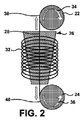
図1は、バルクFe16N2永久磁石の形成技術の例を示す工程系統図である。図1の技術は、図2〜5と並行的に関連させて記述されることになる。図2は、鉄線または鉄板に歪みを与え、窒素に曝すことができる装置の概念図を示す。図3は、図2に示したるつぼ加熱ステージの一例の更なる詳細を示す。 FIG. 1 is a process flow diagram showing an example of a technique for forming a bulk Fe 16 N 2 permanent magnet. The technique of FIG. 1 will be described in parallel with FIGS. FIG. 2 shows a conceptual diagram of an apparatus that can strain an iron wire or iron plate and expose it to nitrogen. FIG. 3 shows further details of an example of the crucible heating stage shown in FIG.
図2の装置の例は、第一ローラー22、第二ローラー24、およびるつぼ加熱ステージ26を含む。第一ローラー22および第二ローラー24は、鉄線または鉄板28のそれぞれ第一端38および第二端40を受けるように構成される。鉄線または鉄板28は、第一端38と第二端40の間で主軸を画定する。図3で最もよく分かるように鉄線または鉄板28は、るつぼ加熱ステージ26によって画定される開口部30を通過する。るつぼ加熱ステージ26は、るつぼ加熱ステージ26によって画定される開口部30の少なくとも一部を取り囲む誘導子32を含む。
The example apparatus of FIG. 2 includes a
図1の技術の例は、鉄線または鉄板28中の少なくとも1個の鉄結晶の<001>軸に実質上平行(例えば、平行またはほぼ平行)な方向に沿ってその鉄線または鉄板28に歪みを与えるステップ(12)を含む。幾つかの例では鉄線または鉄板28は、体心立方晶(bcc)結晶構造を有する鉄から作られる。
An example of the technique of FIG. 1 is to strain the iron wire or
幾つかの例では鉄線または鉄板28は、単一のbcc結晶構造から作られる。他の例では鉄線または鉄板28は、複数個のbcc結晶構造から作ることもできる。それらの例の幾つかでは複数個の鉄結晶は、個々の単位胞および/または結晶の<001>軸の少なくとも一部、例えば大部分または実質上全部が、鉄線または鉄板28に歪みを加える方向に実質上平行であるように配向される。例えば、鉄が鉄線または鉄板28として形成される場合、<001>軸の少なくとも一部は、図2および3に示すように鉄線または鉄板28の主軸に実質上平行であることができる。上記で注記したように幾つかの例では単結晶窒化鉄の線材または薄板は、るつぼ技術を使用して形成することができる。このようなるつぼ技術に加えて、単結晶の鉄線または鉄板を、マイクロメルトゾーンフローティング法か、またはマイクロシェーパーから引き抜くかのいずれかによって形成して鉄線または鉄板28を形成することもできる。
In some examples, the iron wire or
幾つかの例では鉄線または鉄板28は、結晶集合組織を持つ構造を有することができる。これら技術を使用して結晶集合組織を持つ(例えば、鉄線または鉄板の一定の方向に沿って所望の結晶配向を有する)鉄線または鉄板28を形成することができる。図13は、鉄線または鉄板の例、例えば鉄線または鉄板28に集合組織を持たせるための高速ベルトキャスティング用装置70の一例を示す概念図である。図示のように高速ベルトキャスティング装置70は、溶融鉄の鋳塊72を収容する鋳塊チャンバー76を含む。鋳塊は、例えば加熱コイルの形態の加熱源74によって加熱することができる。鋳塊72は、ノズルヘッド78を経てチャンバー76から流出して鉄ストリップ80を形成する。鉄ストリップ80は、反対方向に回転するピンチローラー82Aおよび82Bの表面間の間隙ゾーンに送り込まれる。幾つかの例ではローラー82Aおよび82Bの回転は、1分当たり約10から1000回転まで変えることができる。鉄ストリップは、ピンチローラー82Aおよび82B上で冷やされ、ピンチローラー82Aと82Bの間で加圧された後、集合組織を持つ鉄ストリップ84Aおよび84Bを形成する。幾つかの例では集合組織を持つ鉄ストリップ84Aおよび84Bは、例えば約1マイクロメートルから約1ミリメートルの間の厚さ(個々にまたは多枚数の鉄ストリップの圧縮後のいずれかで)を有する集合組織を持つ鉄リボンを形成することができる。
In some examples, the iron wire or
歪みのかかっていない鉄bcc結晶格子では、結晶単位胞の<100>軸、<010>軸、および<001>軸は、ほぼ等しい長さを有することができる。しかしながら結晶単位胞に力、例えば張力を結晶軸の一つ、例えば<001>結晶軸に実質上平行な方向に加えた場合、その単位胞は変形することができ、その鉄結晶構造は体心正方晶(bct)と呼ぶことができる。例えば図4は、窒素原子が鉄原子間の格子間隙に埋め込まれている歪みのかかった状態の8個の鉄単位胞を示す概念図である。図4の例は、第一層42中に4個の鉄単位胞を、また第二層44中に4個の鉄単位胞を含む。第二層44は第一層42に被さり、第二層44中のそれら単位胞は、第一層42中の単位胞と実質上一列に整列する(例えば、それら単位胞の<001>結晶軸は層間で実質上一列に整列する)。図4に示すように鉄単位胞は、<001>軸に沿った単位胞の長さが約3.14オングストローム(Å)になり、一方<010>軸および<100>軸に沿った単位胞の長さが約2.86Åになるように変形される。歪みのかかった状態にある場合、この鉄単位胞をbct単位胞と呼ぶことがある。鉄単位胞が歪みのかかった状態にある場合、その<001>軸を単位胞のc−軸と呼ぶことがある。 In an unstrained iron bcc crystal lattice, the <100> axis, the <010> axis, and the <001> axis of the crystal unit cell can have approximately equal lengths. However, when a force, such as tension, is applied to a crystal unit cell in one of the crystal axes, eg, <001> crystal axis, the unit cell can be deformed and its iron crystal structure is It can be called tetragonal crystal (bct). For example, FIG. 4 is a conceptual diagram showing eight iron unit cells in a strained state in which nitrogen atoms are embedded in lattice gaps between iron atoms. The example of FIG. 4 includes four iron unit cells in the first layer 42 and four iron unit cells in the second layer 44. The second layer 44 overlies the first layer 42, and the unit cells in the second layer 44 are substantially aligned with the unit cells in the first layer 42 (eg, the <001> crystal axes of the unit cells). Are substantially aligned in a row between layers). As shown in FIG. 4, the iron unit cell has a unit cell length of about 3.14 angstroms along the <001> axis, while the unit cell along the <010> axis and the <100> axis. Is deformed to have a length of about 2.86 mm. When in a strained state, this iron unit cell may be referred to as a bct unit cell. When the iron unit cell is in a strained state, the <001> axis is sometimes referred to as the c-axis of the unit cell.
歪みは、歪みを生じさせる様々な装置を使用して鉄線または鉄板28に与えることができる。例えば、図2に示すように鉄線または鉄板28の第一端38および第二端40を、それぞれ第一ローラー22および第二ローラー24に受け取らせる(例えば、巻き付ける)ことができ、そのローラー22、24を反対方向(図2中で矢印34および35によって表される)に回転させて鉄線または鉄板28に張力を与えることができる。
Strain can be applied to the iron wire or
他の例では鉄線または鉄板28の両端をメカニカルグリップ、例えばクランプ中に把持することができ、そのメカニカルグリップを互いに離れるように移動させてその鉄線または鉄板28に張力を与えることができる。図6は、本明細書中で述べるように鉄線または鉄板28に歪みを与えることができる装置の別の例を示す概念図である。図示のように装置54はクランプ56および58を含み、それらはねじ60a〜dを締め付けることによって鉄線または鉄板28の両端を固定することができる。鉄線または鉄板が装置19中にいったん固定されたら、ボルト62にボルト62のねじ体の回転を開始させてクランプ56と58の間の距離を増し、鉄線または鉄板28に張力を与えることができる。ボルト62の回転によって生ずる伸びまたは応力の値は、例えば歪みゲージなどの任意の適切な計測器によって測定することができる。幾つかの例では、鉄線または鉄板28が装置54によって引き伸ばされる間および/または後にその鉄線または鉄板28を加熱することができるように装置54を炉(例えば管状炉)または他の加熱環境中に置くことができる。
In another example, both ends of the iron wire or
歪みを生じさせる装置は、一定の伸びまで鉄線または鉄板28に歪みを与えることができる。例えば、鉄線または鉄板28上の歪みは、約0.3%から約7%の間であることができる。他の例では鉄線または鉄板28上の歪みは、約0.3%未満または約7%を超えることもできる。幾つかの例では、鉄線または鉄板28に一定の歪みを与えることによりその鉄の個々の単位胞上にもほぼ似た歪みを生じさせ、その結果、単位胞が<001>軸に沿って約0.3%から約7%の間まで伸ばされるようにすることができる。
A device that produces strain can strain the iron wire or
鉄線または鉄板28は、任意の適切な直径および/または厚さを有することができる。幾つかの例では適切な直径および/または厚さは、マイクロメートル(μm)またはミリメートル(mm)程度であることができる。例えば鉄線は、約10μm(0.01mm)を超える直径を有することができる。幾つかの例では鉄線は、約0.01mmから約1mmの間、例えば約0.1mmの直径を有する。同様に鉄板は、任意の適切な厚さおよび/または幅を有することができる。幾つかの例では鉄板は約0.01mmを超える、例えば約0.01mmから約1mmの間の厚さ、または約0.1mmの厚さを有することができる。幾つかの実施例では鉄板の幅は、その鉄板の厚さを超えることができる。
The iron wire or
鉄線の直径または鉄板の断面積(鉄板が引き伸ばされ/歪みを与えられる方向に実質上直角な平面内の)は、所定の歪みを生じさせるために鉄線または鉄板28に加えなければならない力の量に影響を与える可能性がある。例えば、約0.1mmの直径を有する鉄線に約144Nの力を加えることにより約7%の歪みを生じさせることができる。別の例として、約0.2mmの直径を有する鉄線に約576Nの力を加えることにより約7%の歪みを生じさせることができる。別の例として、約0.3mmの直径を有する鉄線に約1296Nの力を加えることにより約7%の歪みを生じさせることができる。別の例として、約0.4mmの直径を有する鉄線に約2304Nの力を加えることにより約7%の歪みを生じさせることができる。別の例として、約0.5mmの直径を有する鉄線に約3600Nの力を加えることにより約7%の歪みを生じさせることができる。
The diameter of the iron wire or the cross-sectional area of the iron plate (in a plane substantially perpendicular to the direction in which the iron plate is stretched / strained) is the amount of force that must be applied to the iron wire or
幾つかの例では鉄線または鉄板28は、Fe16N2相構成が形成された後のそのFe16N2相構成を安定化させるのに役立つドーパント元素を含むことができる。例えば相安定化ドーパント元素にはコバルト(Co)、チタン(Ti)、銅(Cu)、亜鉛(Zn)などを挙げることができる。
In some examples, the iron wire or
歪みを生じさせる装置が鉄線または鉄板28に歪みを与えるにつれて、かつ/または歪みを生じさせる装置が鉄線または鉄板28にほぼ一定の歪みを与えた後に、鉄線または鉄板2を窒化することができる(14)。幾つかの例では窒化工程の間に加熱装置を使用して鉄線または鉄板28を加熱することができる。鉄線または鉄板28を加熱するために使用することができる加熱装置の一例は、図2および3に示したるつぼ加熱ステージ26である。
The iron wire or
るつぼ加熱ステージ26は、鉄線または鉄板28が通過する(例えば鉄線または鉄板28の一部が配列される)開口部30を画定する。幾つかの例では鉄線または鉄板28の加熱の間、るつぼ加熱ステージ26のどの部分も鉄線または鉄板28と接触しない。幾つかの実施例では、これは望ましくない元素または化学種が鉄線または鉄板28と接触し、その中に拡散するリスクを減らすので有利である。望ましくない元素または化学種は鉄線または鉄板28の特性に影響を及ぼす恐れがあり、したがって鉄線または鉄板28と他の材料の間の接触を減少または限定することが望ましいことがある。
The
るつぼ加熱ステージ26はまた、るつぼ加熱ステージ26によって画定される開口部の少なくとも一部を取り囲む誘導子32を含む。誘導子32は、電流が通過することができる導電性材料、例えばアルミニウム、銀、または銅を含む。この電流は交流電流(AC)であることができ、これは鉄線または鉄板28中に渦電流を引き起こし、鉄線または鉄板28を加熱することができる。他の例では、るつぼ加熱ステージ26を使用して鉄線または鉄板28を加熱する代わりに他の非接触加熱源を使用することもできる。例えば、赤外線加熱ランプなどの輻射熱源を使用して鉄線または鉄板28を加熱することもできる。別の例ではプラズマアークランプを使用して鉄線または鉄板28を加熱することもできる。
The
窒化工程中に鉄線または鉄板28を加熱するために使用される加熱装置に関係なく、その加熱装置は、鉄線または鉄板28の厚さまたは直径のほぼ全体にわたって所定の濃度まで窒素の拡散を可能にするのに十分な時間、或る一定の温度でその鉄線または鉄板28を加熱することができる。このようにその加熱時間と温度は関係しており、また鉄線または鉄板28の組成および/または幾何形状によって影響を受ける場合もある。例えば、鉄線または鉄板28は、約125℃から約600℃の間の温度で、約2時間から約9時間加熱することができる。幾つかの例では鉄線または鉄板28を、約500℃から約600℃の間の温度で、約2時間から約4時間加熱することができる。
Regardless of the heating device used to heat the iron wire or
幾つかの例では鉄線または鉄板28は、約0.1mmの直径を有する鉄線を含む。これらの例の幾つかでは鉄線または鉄板28を、約125℃の温度で約8.85時間、または約600℃の温度で約2.4時間加熱することができる。一般に、所与の温度ではその窒化工程時間は、鉄線または鉄板28の特性寸法、例えば鉄線の直径または鉄板の厚さの二乗に逆比例する。
In some examples, the iron wire or
鉄線または鉄板28を加熱するステップに加えて、鉄線または鉄板28の窒化(14)は、その鉄線または鉄板28を、鉄線または鉄板28中に拡散する原子状窒素物質に曝すステップを含む。幾つかの例では原子状窒素物質を二原子窒素(N2)として供給することができ、次いでそれは分離(分解)して個々の窒素原子になる。他の例では原子状窒素を、アンモニア(NH3)などの別の原子状窒素前駆体から得ることもできる。他の例では原子状窒素を尿素(CO(NH2)2)から得ることができる。
In addition to heating the iron wire or
窒素は、気相単独(例えば、実質的に純粋なアンモニアまたは二原子窒素ガス)で供給することも、キャリヤーガスとの混合物として供給することもできる。幾つかの例ではキャリヤーガスはアルゴン(Ar)である。このガスまたはガス混合物は、任意の適切な圧力、例えば約0.001トル(約0.133パスカル(Pa))から約10トル(約1333Pa)の間、例えば約0.01トル(約1.33Pa)から約0.1トル(約13.33Pa)の間の圧力で供給することができる。幾つかの例では、窒素をキャリヤーガスとの混合物の一部として送り出す場合、窒素または窒素前駆体(例えばNH3)の分圧は約0.02トルから約0.1トルの間であることができる。 Nitrogen can be supplied in the gas phase alone (eg, substantially pure ammonia or diatomic nitrogen gas) or as a mixture with a carrier gas. In some examples, the carrier gas is argon (Ar). The gas or gas mixture may be at any suitable pressure, such as between about 0.001 Torr (about 0.133 Pascal (Pa)) to about 10 Torr (about 1333 Pa), for example about 0.01 Torr (about 1. 33 Pa) to about 0.1 Torr (about 13.33 Pa). In some examples, when nitrogen is delivered as part of a mixture with a carrier gas, the partial pressure of the nitrogen or nitrogen precursor (eg, NH 3 ) is between about 0.02 Torr and about 0.1 Torr. Can do.
窒素前駆体(例えば、N2またはNH3)を様々な技術を用いて分解して原子状窒素物質を形成することができる。例えば、輻射を用いて窒素前駆体を加熱して原子状窒素物質を形成する、かつ/または窒素前駆体と鉄線または鉄板28との間の反応を促進させることができる。別の例として、プラズマアークランプを用いて窒素前駆体を分解して原子状窒素物質を形成する、かつ/または窒素前駆体と鉄線または鉄板28との間の反応を促進させることができる。
Nitrogen precursors (eg, N 2 or NH 3 ) can be decomposed using a variety of techniques to form atomic nitrogen materials. For example, the nitrogen precursor can be heated using radiation to form an atomic nitrogen material and / or the reaction between the nitrogen precursor and the iron wire or
幾つかの例では鉄線または鉄板28は、尿素拡散法により窒化することができる(14)。この場合、尿素が窒素源(例えば、二原子窒素またはアンモニアではなく)として利用される。尿素(カルバミドとも呼ばれる)は時には窒素放出肥料として使用されることもある化学式CO(NH2)2を有する有機化合物である。鉄線または鉄板28を窒化する(14)には、尿素を鉄線または鉄板28と一緒に、例えば炉内で加熱して、鉄線または鉄板28中に拡散することができる分解窒素原子を発生させる。下記でさらに述べることにするが、得られる窒化された鉄材料の構成は、拡散工程の温度、および鉄とその工程に使用された尿素の比(例えば重量比)によってある程度は制御することができる。他の例では鉄線または鉄板28は、半導体工程でドーピング剤を導入するために使用される方法に似た注入法によって窒化することもできる。
In some examples, the iron wire or
図7は、尿素拡散法により鉄線または鉄板28を窒化するために使用することができる装置の例64を示す略図である。そのような尿素拡散法は、例えば単結晶鉄、複数の結晶構造、または集合組織を持つ構造を有する場合に鉄線または鉄板28の窒化に使用することができる。さらに、線材、薄板、またはバルクなどの様々な形状を有する鉄材料にもまた、このような方法を使用して拡散することができる。線材料の場合、線径は、数マイクロメートルから数ミリメートルまで変えることができる。板材料の場合、板厚は、例えば数ナノメートルから数ミリメートルであることができる。バルク材の場合、材料の重量は、例えば約1ミリグラムから数キログラムであることができる。
FIG. 7 is a schematic diagram illustrating an
図示のように装置64は、真空炉68の内部にるつぼ66を含む。鉄線または鉄板28は、窒素供給源の尿素72と共にるつぼ66内に置かれる。図7に示すようにArおよび水素を含むキャリヤーガスが、尿素拡散工程の間ずっとるつぼ66中に供給される。他の例では別のキャリヤーガス、またはキャリヤーガスなしですら使用することができる。幾つかの例では尿素拡散工程の間の真空炉68内のガス流量は、約5標準状態立方センチメートル毎分(standard cubic centimeters per minute)(sccm)から約50sccmの間、例えば20標準状態立方センチメートル毎分(sccm)から約50sccmの間、または5標準状態立方センチメートル毎分(sccm)から約20sccmの間などであることができる。
As shown, the
加熱コイル70は、任意の適切な技術、例えば渦電流、誘導電流、高周波などを使用して尿素拡散工程の間に鉄線または鉄板28と尿素72を加熱することができる。るつぼ66は、尿素拡散工程中に使用される温度に耐えるように構成することができる。幾つかの例では、るつぼ66は約1600℃までの温度に耐えることができる。
The
尿素72を鉄線または鉄板28と共に加熱して、窒化鉄材料を形成するために鉄線または鉄板28中に拡散することができる窒素を発生させることができる。幾つかの例では鉄線または鉄板28と尿素72を、るつぼ66内で約650℃以上まで加熱し、続いて冷却して鉄と窒素の混合物を焼入れし、鉄線または鉄板28の厚さまたは直径のほぼ全域にわたってFe16N2相構成を有する窒化鉄材料を形成することができる。幾つかの例では尿素72と鉄線または鉄板28を、るつぼ66内で約5分から約1時間、約650℃以上に加熱することができる。幾つかの例では尿素72と鉄線または鉄板28を、数分から約1時間、約1000℃から約1500℃の間で加熱することができる。加熱時間は、尿素72および鉄線または鉄板28を加熱する温度によって決まる。例えば、その鉄線または鉄板28が約1マイクロメートルの厚さの場合、拡散工程は約1200℃では約5分、1100℃では約12分などで終えることができる。
加熱された材料を焼入れ工程の間に冷却するには、内容物を急速に冷却するために、るつぼの外側に冷水を循環させることができる。幾つかの例では温度を、約20秒で650℃から室温まで下げることができる。 To cool the heated material during the quenching process, cold water can be circulated outside the crucible to rapidly cool the contents. In some examples, the temperature can be reduced from 650 ° C. to room temperature in about 20 seconds.
下記で述べるように幾つかの例では、鉄と窒素の混合物を焼鈍して鉄線または鉄板28の厚さまたは直径のほぼ全域にわたってFe16N2相構成を有する窒化鉄材料を形成するには、尿素72と鉄線または鉄板28の温度は、例えば約200℃から約150℃の間であることができる。尿素72と鉄線または鉄板28は、この焼鈍温度において、例えば約1時間から約40時間の間であることができる。例えばその鉄材料が単結晶の鉄線および鉄板であるか、またはマイクロメートルレベルの厚さを有する集合組織を持つ鉄線および鉄板である場合、このような焼鈍工程を他の窒素拡散技術に加えて、またはその代替手段として使用することができる。焼鈍および焼入れのステップのそれぞれにおいて窒素は、炉68内で窒素ガスまたはArプラス水素キャリヤーガスを含むガス混合物から鉄線または鉄板28中に拡散させることができる。幾つかの例ではガス混合物は、Ar約86%+H24%+N210%の組成を有することができる。他の例ではガス混合物は、N210%+Ar90%、またはN2100%、またはAr100%の組成を有することができる。
In some examples, as described below, annealing a mixture of iron and nitrogen to form an iron nitride material having a Fe 16 N 2 phase configuration over substantially the entire thickness or diameter of the iron wire or
下記でさらに述べることにするが尿素拡散法により形成される窒化鉄材料の構成は、使用される尿素対鉄の重量比によって決まる。したがって幾つかの例では、尿素対鉄の重量比を選択してFe16N2相構成を有する窒化鉄材料を形成することができる。しかしながらそのような尿素拡散工程は、Fe16N2相構成を有するもの以外の窒化鉄材料、例えばFe2N、Fe3N、Fe4N、Fe8Nなどを形成するためにも使用することができる。さらに尿素拡散工程は、鉄以外の材料中に窒素を拡散させるためにも使用することができる。例えばこのような尿素拡散工程は、インジウム、FeCo、FePt、CoPt、コバルト、Zn、Mnなどの中に窒素を拡散させるために使用することができる。 As will be described further below, the composition of the iron nitride material formed by the urea diffusion method depends on the weight ratio of urea to iron used. Thus, in some examples, a weight ratio of urea to iron can be selected to form an iron nitride material having a Fe 16 N 2 phase configuration. However, such a urea diffusion process should also be used to form iron nitride materials other than those having a Fe 16 N 2 phase configuration, such as Fe 2 N, Fe 3 N, Fe 4 N, Fe 8 N, etc. Can do. Furthermore, the urea diffusion process can also be used to diffuse nitrogen in materials other than iron. For example, such a urea diffusion process can be used to diffuse nitrogen into indium, FeCo, FePt, CoPt, cobalt, Zn, Mn, and the like.
鉄線または鉄板28を窒化する(14)ために使用される技術には関係なく、窒素は約8原子百分率(at.%)〜約14at.%、例えば約11at.%の濃度まで鉄線または鉄板28中に拡散することができる。鉄中のこの窒素濃度は平均濃度であることができ、また鉄線または鉄板28の体積全体にわたって変えることもできる。幾つかの例では窒化された鉄線または鉄板28(鉄線または鉄板28を窒化(14)した後の)の少なくとも一部分のその得られる相構成はα’相Fe8Nであることができる。Fe8N相構成は、化学的規則性を持つFe16N2相の化学的不規則性を持つ対等物である。またFe8N相構成はbct結晶細胞を有し、比較的高い結晶磁気異方性を導入することができる。
Regardless of the technique used to nitride (14) the iron wire or
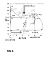
幾つかの例では、窒化された鉄線または鉄板28はα”相Fe16N2であることができる。図8は、鉄−窒素の状態図である。図8に示すように、約11at.%Nの原子百分率においてはα”相Fe16N8は、Fe−N混合物を約650℃を超える温度で適切な時間焼入れすることによって形成することができる。さらに、約11at.%Nの原子百分率においてはα”相Fe16N8は、Fe−N混合物を約200℃未満の温度で適切な時間焼鈍することによっても形成することができる。
In some examples, the nitrided iron wire or
幾つかの例では、鉄線または鉄板28を窒化した(14)後に、鉄線または鉄板28を或る一定温度で或る一定時間焼鈍して鉄格子内の適切な間隙中への窒素原子の拡散を容易にし、Fe16N2相を形成することもできる(16)。図4は、窒素原子が位置付けられている鉄結晶格子の適切な間隙の例を示す。幾つかの例では、窒化された鉄線または鉄板28を、約100℃から約300℃の間の温度で焼鈍することができる。他の例では、焼鈍温度は、約126.85℃(約400ケルビン)であることができる。窒化された鉄線または鉄板28は、るつぼ加熱ステージ26、プラズマアークランプ、輻射熱源(例えば赤外線加熱ランプ)、オーブン、または密閉されたレトルトを使用して焼鈍することができる。
In some examples, after nitriding (14) the iron wire or
焼鈍工程は、適切な間隙への窒素原子の拡散を可能にするのに十分な所定の時間のあいだ続けることができる。幾つかの例では焼鈍工程は、約20時間から約100時間、例えば約40時間から約60時間続く。幾つかの例では焼鈍工程は、鉄の酸化を減らすまたは実質上防止するためにArなどの不活性雰囲気中で行うことができる。幾つかの実施例では、鉄線または鉄板28が焼鈍される(16)間、その温度はほぼ一定に保たれる。
The annealing process can be continued for a predetermined time sufficient to allow diffusion of nitrogen atoms into the appropriate gap. In some examples, the annealing step lasts from about 20 hours to about 100 hours, such as from about 40 hours to about 60 hours. In some examples, the annealing step can be performed in an inert atmosphere such as Ar to reduce or substantially prevent oxidation of the iron. In some embodiments, the temperature is kept approximately constant while the iron wire or
焼鈍工程が完了した後、鉄線または鉄板28はFe16N2相構成を含むことができる。幾つかの実施例では、鉄線または鉄板28の少なくとも一部分は、実質上Fe16N2相構成からなる。本明細書中で使用される「から実質上なる」とは、その鉄線または鉄板28が、Fe16N2と、そのFe16N2相の基本的かつ新規な特性に著しい影響を与えない他の材料とを含むことを意味する。他の例では鉄線または鉄板28は、Fe16N2相構成と、例えば鉄線または鉄板28の別の部分にFe8N相構成とを含むことができる。その線材および薄板中の、またこの後者の加圧された集成材中のFe8N相構成およびFe16N2相構成は、量子力学の実用的原則により磁気的に交換結合することができる。これは、いわゆる交換スプリング磁石を形成することができ、それはFe8Nのごく一部だけでさえ磁気エネルギー積を増すことができる。
After the annealing process is completed, the iron wire or
幾つかの例では、下記でさらに詳細に述べるように鉄線または鉄板28は、磁区壁ピン止めサイトとして働くドーパント元素または欠陥を含むことができ、これらは鉄線または鉄板28の保磁力を高めることができる。本明細書中で使用される実質上Fe16N2相構成からなる鉄線または鉄板28は、磁壁ピン止めサイトとして働くドーパント元素または欠陥を含むことができる。他の例では、下記でさらに詳細に述べるように鉄線または鉄板28は、結晶粒界として働く非磁性ドーパント元素を含むことができ、それらは鉄線または鉄板の保磁力を高めることができる。本明細書中で使用されるFe16N2相構成からなる鉄線または鉄板28は、結晶粒界として働く非磁性元素を含むことができる。
In some examples, as described in more detail below, the iron wire or
焼鈍工程が完了した後、鉄線または鉄板28は、酸化を減らすまたは防止するためにアルゴンなどの不活性雰囲気中で冷却することができる。
After the annealing process is completed, the iron wire or
幾つかの例では鉄線または鉄板28は、所望の用途にとって十分なサイズでない場合もある。このような例では複数本(枚)の鉄線または鉄板28を形成し(それぞれがFe16N2相構成を含むか、または実質上Fe16N2相構成からなる)、それら複数本(枚)の鉄線または鉄板28を合わせて加圧して、Fe16N2相構成を含むか、または実質上Fe16N2相構成からなるより大きな永久磁石を形成することができる(18)。
In some examples, the iron wire or
図5Aおよび5Bは、圧縮工程の例を示す概念図である。図5Aに示すように、複数本(枚)の鉄線または鉄板28は、それぞれの鉄線または鉄板28の<001>軸が実質上整列するように配置される。それぞれの鉄線または鉄板28の<001>軸がその鉄線または鉄板28の長軸に実質上平行な例では、鉄線または鉄板28を実質上整列させることは、1本(枚)の鉄線または鉄板28を、別の鉄線または鉄板28上に重ねることを含むことができる。それぞれの鉄線または鉄板28の<001>軸を整列させることにより、永久磁石52に一軸磁気異方性を与えることができる。
5A and 5B are conceptual diagrams illustrating an example of the compression process. As shown in FIG. 5A, a plurality (sheets) of iron wires or
この複数本(枚)の鉄線または鉄板28を、例えば冷間圧縮または熱間圧縮を使用して圧縮することができる。幾つかの例では圧縮が行われる温度は、Fe16N2が約300℃を超えると分解し始めるので約300℃未満であることができる。圧縮は、その複数本(枚)の鉄線または鉄板28をつなぎ合わせて図5Bに示すような実質上一軸の永久磁石52にするのに十分な圧力および時間で行うことができる。
The plurality (sheets) of iron wire or
任意の本数(枚数)の鉄線または鉄板28を合わせて加圧して永久磁石52を形成することができる。幾つかの例では永久磁石52は、少なくとも一つの寸法が少なくとも0.1mmの大きさを有する。幾つかの例では永久磁石52は、少なくとも一つの寸法が少なくとも1mmの大きさを有する。幾つかの例では永久磁石52は、少なくとも一つの寸法が少なくとも1cmの大きさを有する。
An arbitrary number (number) of iron wires or
幾つかの例では、望ましい高保磁力を与えるために鉄線または鉄板28および/または永久磁石52内の磁区の移動を制御することが望ましい場合がある。磁区の移動を制御することができる一つの方法は、鉄線または鉄板28および/または永久磁石52中へ磁区壁ピン止めサイトを導入することによるものである。幾つかの例では、磁区壁ピン止めサイトは、鉄結晶格子中に欠陥を導入することによって形成することができる。それら欠陥は、鉄結晶格子中にドーパント元素を注入することにより、または鉄結晶格子の機械的圧迫により導入することができる。幾つかの例では欠陥は、窒素の導入およびFe16N2相構成の形成の前に鉄結晶格子中に導入することができる。他の例では欠陥は、鉄線または鉄板28を焼鈍してFe16N2を形成(16)した後に導入することができる。磁区壁ピン止めサイトとして働く欠陥を鉄線または鉄板28中に導入することが可能な一例は、鉄結晶格子中へのホウ素(B)、銅(Cu)、炭素(C)、ケイ素(Si)などのイオンボンバードである。他の例では非磁性元素または化合物(例えば、Cu、Ti、Zr、Ta、SiO2、Al2O3など)からなる粉末を、Fe16N2相からなる鉄線および鉄板と一緒に加圧することもできる。数ナノメートル〜数百ナノメートルの範囲のサイズを有するこれらの非磁性粉末は、加圧工程後にFe16N2相の結晶粒界として機能する。これらの結晶粒界は、永久磁石の保磁力を高めることができる。
In some examples, it may be desirable to control the movement of the magnetic domains within the iron wire or
窒化鉄に関して述べたが、また本明細書中で述べる工程の例のうちの一つまたは複数をFeCo合金に応用して、単結晶または高度な集合組織を持つFeCo線材または薄板を形成することもできる。Fe格子中のFe原子の一部をCo原子で置き換えて結晶磁気異方性を高めることができる。さらに、本明細書中で述べた歪みを伴う拡散法の例のうちの一つまたは複数はまた、これらのFeCo線材または薄板に応用することができる。さらにまた、これら工程の例のうちの一つまたは複数を応用して、FeまたはFeCoの線材または薄板中に炭素(C)ホウ素(B)、およびリン(P)の原子を、あるいはFeまたはFeCoの線材または薄板中にN原子と共に部分的にC、P、Bを拡散させることもできる。したがってまた、本明細書中で述べた方法をFeCo合金に応用して単結晶または高度な集合組織を持つFeCo線材または薄板を形成することもできる。また、Fe格子中のFe原子の一部をCo原子で置き換えて、例えば結晶磁気異方性を高めることができる。さらにまた、本明細書中で述べた方法を応用して、FeまたはFeCoの線材または薄板中に炭素(C)ホウ素(B)、およびリン(P)の原子を、あるいはFeまたはFeCoの線材または薄板中にN原子と共に部分的にC、P、Bを拡散させることもできる。さらに、本明細書中で述べた工程に使用される鉄は、線材、薄板の形状、またはバルクの形態を取ることもできる。 Although described with respect to iron nitride, one or more of the process examples described herein may also be applied to an FeCo alloy to form a single crystal or highly textured FeCo wire or sheet. it can. It is possible to increase the magnetocrystalline anisotropy by replacing a part of Fe atoms in the Fe lattice with Co atoms. Further, one or more of the strained diffusion methods described herein can also be applied to these FeCo wires or sheets. Furthermore, by applying one or more of these process examples, carbon (C) boron (B) and phosphorus (P) atoms in Fe or FeCo wire or sheet, or Fe or FeCo. It is also possible to partially diffuse C, P, and B together with N atoms in the wire or thin plate. Therefore, the method described herein can also be applied to an FeCo alloy to form a single crystal or a highly textured FeCo wire or sheet. Further, by replacing some Fe atoms in the Fe lattice with Co atoms, for example, the magnetocrystalline anisotropy can be increased. Furthermore, by applying the method described herein, carbon (C) boron (B) and phosphorus (P) atoms in Fe or FeCo wire or thin plate, or Fe or FeCo wire or It is also possible to partially diffuse C, P, and B together with N atoms in the thin plate. Further, the iron used in the processes described herein can take the form of a wire, thin plate, or bulk.
本明細書中で述べた窒化鉄材料の実例の1または複数の態様を評価するために一連の実験を行った。具体的には実例としての様々な窒化鉄材料を尿素拡散により形成し、次いで評価した。尿素対バルク鉄の重量比への窒化鉄材料の構成の依存度を求めるためにその比を様々に変えた。図12に示すように、約0.5(すなわち1:2)、1.0、1.2、1.6、および2.0の尿素対バルク鉄の重量比を用いて5種類の異なる例を形成した。 A series of experiments were conducted to evaluate one or more aspects of the iron nitride material examples described herein. Specifically, various illustrative iron nitride materials were formed by urea diffusion and then evaluated. In order to determine the dependence of the composition of iron nitride material on the weight ratio of urea to bulk iron, the ratio was varied. As shown in FIG. 12, five different examples using urea to bulk iron weight ratios of about 0.5 (ie 1: 2), 1.0, 1.2, 1.6, and 2.0. Formed.
参考のために、上述の尿素拡散工程の主な化学反応は、約1573℃を超える温度において、
Co(NH2)2→NH3+HNCO (1)
HNCO+H2O→2NH3+CO2 (2)
2NH3→2N+3H2 (3)
2N→N2 (4)
である。このような反応過程では窒素原子の場合、式(4)に示すように再結合して分子になるのが比較的容易である。したがって幾つかの例では、尿素拡散工程の間ずっと尿素をバルク鉄材料の隣りまたはすぐ近くに置くことによって窒素原子の再結合を減らすことができる。例えば幾つかの事例では、尿素はバルク鉄材料の表面と直接に接していることも、またバルク材料の約1センチメートル以内にあることもできる。
For reference, the main chemical reaction of the above urea diffusion step is at a temperature above about 1573 ° C.
Co (NH 2 ) 2 → NH 3 + HNCO (1)
HNCO + H 2 O → 2NH 3 + CO 2 (2)
2NH 3 → 2N + 3H 2 (3)
2N → N 2 (4)
It is. In such a reaction process, in the case of a nitrogen atom, it is relatively easy to recombine into a molecule as shown in Formula (4). Thus, in some instances, nitrogen atom recombination can be reduced by placing urea next to or close to the bulk iron material throughout the urea diffusion process. For example, in some cases, urea can be in direct contact with the surface of the bulk iron material or within about 1 centimeter of the bulk material.
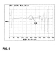
これら窒化鉄試料は、本明細書中で述べた尿素拡散法により調製された。尿素拡散法による窒化鉄試料の調製の後、オージェ電子分光法を用いてこれら実例としての鉄材料の表面の化学組成を決定した。図9は、これら例の一つに対するオージェ測定結果のグラフであり、材料中の窒素の存在を示している。 These iron nitride samples were prepared by the urea diffusion method described herein. After the preparation of iron nitride samples by the urea diffusion method, the chemical composition of the surface of these illustrative iron materials was determined using Auger electron spectroscopy. FIG. 9 is a graph of Auger measurement results for one of these examples, showing the presence of nitrogen in the material.
図12は、尿素対尿素拡散工程で使用したバルク鉄材料の重量比に対する最終窒化鉄材料の窒素濃度(at.%)の関係のグラフである。上記で判るように、この場合、尿素対バルク鉄材料については0.5(すなわち1:2)、1.0、1.2、1.6、および2.0の比が使用された。図12に示すように尿素対バルク鉄材料の異なる重量比は、尿素拡散後の窒化鉄材料内に異なる窒素濃度を生じさせることができる。具体的には図12は、バルク鉄の量を基準にした使用される尿素の量が増加するにつれて、窒化鉄材料中の窒素の原子比が増加したことを示す。したがって、少なくとも幾つかの事例では尿素拡散により形成される窒化鉄材料の所望の窒素濃度は、その所望の窒素濃度に相当する出発材料中の尿素対鉄の重量比を使用することによって得ることができる。 FIG. 12 is a graph of the nitrogen concentration (at.%) Of the final iron nitride material versus the weight ratio of the bulk iron material used in the urea to urea diffusion process. As can be seen above, in this case ratios of 0.5 (ie 1: 2), 1.0, 1.2, 1.6, and 2.0 were used for the urea to bulk iron material. As shown in FIG. 12, different weight ratios of urea to bulk iron material can produce different nitrogen concentrations in the iron nitride material after urea diffusion. Specifically, FIG. 12 shows that as the amount of urea used, based on the amount of bulk iron, increased, the atomic ratio of nitrogen in the iron nitride material increased. Thus, in at least some cases, the desired nitrogen concentration of the iron nitride material formed by urea diffusion can be obtained by using the urea to iron weight ratio in the starting material corresponding to that desired nitrogen concentration. it can.
図10は、窒化鉄材料の表面からの深さに対する、約2.0の尿素対鉄の重量比で始まる尿素拡散により形成される窒化鉄材料の濃度(at.%)の関係のグラフである。図10に示すように、窒化鉄材料の表面からその材料の表面下約1600オングストロームまでの窒素の濃度は約6at.%であった。さらに、酸素および炭素については少しの痕跡も存在せず、これは他のドーパント源が効果的に減少されていることを意味する。 FIG. 10 is a graph of the concentration (at.%) Of iron nitride material formed by urea diffusion starting with a weight ratio of urea to iron of about 2.0 versus depth from the surface of the iron nitride material. . As shown in FIG. 10, the concentration of nitrogen from the surface of the iron nitride material to about 1600 angstroms below the surface of the material is about 6 at. %Met. Furthermore, there is no trace of oxygen and carbon, which means that other dopant sources are effectively reduced.
図11は、窒化鉄材料の表面からの深さに対する、約1.0の尿素対鉄の重量比で始まる尿素拡散により形成される窒化鉄材料の濃度(at.%)の関係のグラフである。図11に示すように、窒化鉄材料の表面からその材料の表面下約800オングストロームまでの窒素の濃度は約6〜12at.%であった。幾つかの例では、例えばより大きな流れを引き起こすポンプシステムを使用するなどの真空システムの改良によってその濃度をさらに低減させることができる。また図示されているように酸素は約4at.%まで減少した。10at.%を超える炭素が存在するが、それは窒素の代替元素とみなすことができるので製造される永久磁石に著しい負の影響を与えない。 FIG. 11 is a graph of the relationship (at.%) Of the concentration of iron nitride material formed by urea diffusion starting with a weight ratio of urea to iron of about 1.0 versus depth from the surface of the iron nitride material. . As shown in FIG. 11, the concentration of nitrogen from the surface of the iron nitride material to about 800 angstroms below the surface of the material is about 6-12 at. %Met. In some instances, the concentration can be further reduced by improvements in the vacuum system, such as using a pump system that causes greater flow. As shown, oxygen is about 4 at. %. 10 at. Although more than% carbon is present, it can be considered as an alternative element for nitrogen, so it does not have a significant negative impact on the manufactured permanent magnet.
様々な例について述べてきた。これらおよび他の例は、下記の特許請求の範囲の範囲に入る。本発明の実施態様の一部を以下の項目[1]−[87]に記載する。
[1]
少なくとも1個の鉄結晶を含む鉄線または鉄板を前記鉄結晶の<001>結晶軸に実質上平行な方向に歪ませるステップ、
前記鉄線または鉄板を窒化して窒化された鉄線または鉄板を形成するステップ、および
前記窒化された鉄線または鉄板を焼鈍して、前記窒化された鉄線または鉄板の少なくとも一部分でFe 16 N 2 相構成を形成させるステップ
を含む方法。
[2]
前記鉄線または鉄板が、単一鉄結晶構造または集合組織構造を含む、項目1に記載の方法。
[3]
前記鉄線または鉄板が複数個の鉄結晶を含み、かつ前記少なくとも1個の鉄結晶を含む前記鉄線または鉄板を前記鉄結晶の前記<001>結晶軸に実質上平行な方向に歪ませるステップが、前記複数個の鉄結晶を含む前記鉄線または鉄板を前記複数個の鉄結晶のうちの少なくとも幾つかの前記<001>結晶軸に実質上平行な方向に歪ませるステップを含む、項目1に記載の方法。
[4]
前記鉄線または鉄板が前記鉄線を含み、かつ前記鉄線が主軸を画定し、かつ前記少なくとも1個の鉄結晶を含む前記鉄線または鉄板を前記鉄結晶の前記<001>結晶軸に実質上平行な方向に歪ませるステップが、前記鉄線を前記鉄線の前記主軸に実質上平行な方向に歪ませるステップを含む、項目1に記載の方法。
[5]
前記少なくとも1個の鉄結晶を含む前記鉄線または鉄板を前記鉄結晶の前記<001>結晶軸に実質上平行な方向に歪ませるステップが、前記鉄線または鉄板の第一端を第一の方向に引っ張り、かつ前記鉄線または鉄板の前記第二端を前記第一の方向と実質上反対の第二の方向に引っ張ることによって前記鉄線または鉄板に引張力を加えるステップを含む、項目1に記載の方法。
[6]
前記少なくとも1個の鉄結晶を含む前記鉄線または鉄板を前記鉄結晶の前記<001>結晶軸に実質上平行な方向に歪ませるステップが、前記少なくとも1個の鉄結晶を含む前記鉄線または鉄板を前記鉄結晶の前記<001>結晶軸に実質上平行な方向に約0.3%から約7%の間の歪みまで歪ませるステップを含む、項目1に記載の方法。
[7]
前記鉄線または鉄板を窒化して前記窒化された鉄線または鉄板を形成するステップが、前記鉄線または鉄板を約125℃から約600℃の間の温度に加熱するステップを含む、項目1に記載の方法。
[8]
前記鉄線または鉄板を約125℃から約600℃の間の温度に加熱するステップが、前記鉄線または鉄板を約125℃の温度で約8.85時間加熱するステップを含む、項目7に記載の方法。
[9]
前記鉄線または鉄板を約125℃から約600℃の間の温度に加熱するステップが、前記鉄線または鉄板を約600℃の温度で約2.4時間加熱するステップを含む、項目7に記載の方法。
[10]
前記鉄線または鉄板を窒化して前記窒化された鉄線または鉄板を形成するステップが、前記鉄線または鉄板を原子状窒素物質に曝すステップを含む、項目1に記載の方法。
[11]
前記原子状窒素物質が、N 2 ガスまたはNH 3 ガスの中の少なくとも1種類を含む窒素前駆体から形成される、項目10に記載の方法。
[12]
前記窒素前駆体がキャリヤーガスと混合される、項目11に記載の方法。
[13]
前記窒素前駆体が、約0.02から約0.1の間の分圧まで前記キャリヤーガスと混合される、項目12に記載の方法。
[14]
前記鉄線または鉄板を前記原子状窒素物質に曝すステップが、前記鉄線または鉄板を約0.133Paから約1333Paの間の圧力で窒素前駆体に曝すステップを含む、項目10に記載の方法。
[15]
前記窒化された鉄線または鉄板を焼鈍して前記窒化された鉄線または鉄板の少なくとも前記一部分で前記Fe 16 N 2 相構成を形成させるステップが、前記窒化された鉄線または鉄板を約100℃から約300℃の間で加熱するステップを含む、項目1に記載の方法。
[16]
前記窒化された鉄線または鉄板を焼鈍して前記窒化された鉄線または鉄板の少なくとも前記一部分で前記Fe 16 N 2 相構成を形成させるステップが、前記窒化された鉄線または鉄板を約100℃から約300℃の間で約20時間から約100時間加熱するステップを含む、項目1に記載の方法。
[17]
前記窒化された鉄線または鉄板を焼鈍して前記窒化された鉄線または鉄板の少なくとも前記一部分で前記Fe 16 N 2 相構成を形成させるステップが、前記窒化された鉄線または鉄板を不活性雰囲気下で焼鈍するステップを含む、項目1に記載の方法。
[18]
Fe 16 N 2 相構成を含む複数本(枚)の鉄線または鉄板を圧縮してFe 16 N 2 相構成を含む永久磁石を形成するステップをさらに含む、項目1に記載の方法。
[19]
前記Fe 16 N 2 相構成を含む前記複数本(枚)の窒化された鉄線または鉄板を圧縮して前記Fe 16 N 2 相構成を含む前記永久磁石を形成するステップが、前記Fe 16 N 2 相構成を含む前記多数本(枚)の窒化された鉄線または鉄板を冷間圧縮して前記Fe 16 N 2 相構成を含む前記永久磁石を形成するステップを含む、項目18に記載の方法。
[20]
前記Fe 16 N 2 相構成を含む前記複数本(枚)の窒化された鉄線または鉄板を圧縮して前記Fe 16 N 2 相構成を含む前記永久磁石を形成するステップが、前記Fe 16 N 2 相構成を含む第一の窒化された鉄線または鉄板の<001>結晶軸を、前記Fe 16 N 2 相構成を含む第二の窒化された鉄線または鉄板の<001>結晶軸と、前記第一の窒化された鉄線または鉄板および前記第二の鉄線または鉄板の圧縮に先立って実質上一列に整列させるステップを含む、項目18に記載の方法。
[21]
前記Fe 16 N 2 相構成を含む前記複数本(枚)の鉄線または鉄板を圧縮して前記Fe 16 N 2 相構成を含む前記永久磁石を形成するステップが、前記Fe 16 N 2 相構成を含む前記複数本(枚)の鉄線または鉄板を圧縮して、前記Fe 16 N 2 相構成を含み、かつ少なくとも0.1mmの少なくとも1つの寸法が大きさを画定する前記永久磁石を形成するステップを含む、項目18に記載の方法。
[22]
前記Fe 16 N 2 相構成を含む前記複数本(枚)の鉄線または鉄板を圧縮して前記Fe 16 N 2 相構成を含む前記永久磁石を形成するステップが、前記Fe 16 N 2 相構成を含む前記複数本(枚)の鉄線または鉄板を圧縮して、前記Fe 16 N 2 相構成を含み、かつ少なくとも1mmの少なくとも1つの寸法が大きさを画定する前記永久磁石を形成するステップを含む、項目18に記載の方法。
[23]
前記鉄線または鉄板を窒化して前記窒化された鉄線または鉄板を形成するステップが、前記鉄線または鉄板を原子状窒素物質に曝すステップを含み、前記原子状窒素物質が尿素から形成される、項目1に記載の方法。
[24]
前記Fe 16 N 2 相構成を含む前記窒化された鉄線または鉄板中に磁区壁ピン止めサイトを導入するステップをさらに含む、項目1に記載の方法。
[25]
前記Fe 16 N 2 相構成を含む前記窒化された鉄線または鉄板中に磁区壁ピン止めサイトを導入するステップが、前記Fe 16 N 2 相構成を含む前記窒化された鉄線または鉄板をドーパント元素でイオンボンバード処理するステップを含む、項目24に記載の方法。
[26]
前記少なくとも1個の鉄結晶を含む前記鉄線または鉄板を前記鉄結晶の前記<001>結晶軸に実質上平行な方向に歪ませるステップの前に、前記窒化された鉄線または鉄板中に磁区壁ピン止めサイトを導入するステップをさらに含む、項目1に記載の方法。
[27]
前記窒化された鉄線または鉄板中に磁区壁ピン止めサイトを導入するステップが、前記窒化された鉄線または鉄板をドーパント元素でイオンボンバード処理するステップを含む、項目26に記載の方法。
[28]
Co、Ti、Cu、またはZnのうちの少なくとも1種類を含む相安定化ドーパント元素を前記鉄線または鉄板中に導入するステップをさらに含む、項目1に記載の方法。
[29]
少なくとも1個の体心立方晶(bcc)鉄結晶を含む鉄線または鉄板に前記bcc鉄結晶の<001>軸に実質上平行な方向に歪みを与えるように構成された歪みを生じさせる装置、
前記歪みのかかった鉄線または鉄板を加熱するように構成された第一加熱装置、
前記歪みのかかった鉄線または鉄板を原子状窒素物質に曝して窒化された鉄線または鉄板を形成するように構成された前記原子状窒素物質の供給源、および
前記窒化された鉄線または鉄板を焼鈍して前記窒化された鉄線または鉄板の少なくとも一部分でFe 16 N 2 相構成を形成させるのに十分な温度まで前記窒化された鉄線または鉄板を加熱するように構成された第二加熱装置
を含むシステム。
[30]
Fe 16 N 2 相構成を含む複数本(枚)の窒化された鉄線または鉄板を圧縮してFe 16 N 2 相構成を含む実質上単一の永久磁石を形成させるように構成されたプレスをさらに含む、項目29に記載のシステム。
[31]
前記プレスが、前記Fe 16 N 2 相構成を含む複数本(枚)の窒化された鉄線または鉄板を圧縮して、前記Fe 16 N 2 相構成を含み、かつ少なくとも0.1mmの少なくとも1つの寸法が大きさを画定する実質上単一の永久磁石を形成させるように構成される、項目30に記載のシステム。
[32]
前記プレスが、前記Fe 16 N 2 相構成を含む複数本(枚)の窒化された鉄線または鉄板を圧縮して、前記Fe 16 N 2 相構成を含み、かつ少なくとも1mmの少なくとも1つの寸法が大きさを画定する実質上単一の永久磁石を形成させるように構成される、項目30に記載のシステム。
[33]
前記原子状窒素物質の前記供給源が尿素を含む、項目29に記載のシステム。
[34]
前記窒化された鉄線または鉄板中に磁区壁ピン止めサイトを導入するための手段をさらに含む、項目29に記載のシステム。
[35]
前記歪みを生じさせる装置が、前記鉄線または鉄板の第一端を受けるように構成された第一ローラーと、前記鉄線または鉄板の第二端を受けるように構成された第二ローラーとを含み、かつ前記第二端が前記第一端の実質上反対の位置にあり、かつ前記第一ローラーおよび前記第二ローラーが、回転して前記鉄線または鉄板の前記第一端と前記鉄線または鉄板の前記第二端の間に引張力を加えるように構成される、項目29に記載のシステム。
[36]
前記第一ローラーおよび前記第二ローラーが、回転して前記鉄線または鉄板に約0.3%から約7.0%の間で歪ませるように構成される、項目35に記載のシステム。
[37]
前記第一加熱装置が、るつぼ加熱ステージを含む、項目29に記載のシステム。
[38]
前記第一加熱装置が、輻射熱源を含む、項目29に記載のシステム。
[39]
前記第一加熱装置が、プラズマアークランプを含む、項目29に記載のシステム。
[40]
前記第二加熱装置が、加熱用るつぼを含む、項目29に記載のシステム。
[41]
前記第二加熱装置が、輻射熱源を含む、項目29に記載のシステム。
[42]
前記第二加熱装置が、プラズマアークランプを含む、項目29に記載のシステム。
[43]
前記第二加熱装置が、オーブンを含む、項目29に記載のシステム。
[44]
前記第二加熱装置が、密閉されたレトルトを含む、項目29に記載のシステム。
[45]
Fe 16 N 2 相構成を含む線材を含む永久磁石。
[46]
前記線材が、少なくとも約0.01ミリメートルの直径を有する、項目45に記載の永久磁石。
[47]
前記線材が、約0.1ミリメートルの直径を有する、項目45に記載の永久磁石。
[48]
前記線材が、約30MGOeを超えるエネルギー積を有する、項目45に記載の永久磁石。
[49]
前記線材が、約60MGOeを超えるエネルギー積を有する、項目45に記載の永久磁石。
[50]
前記線材が、約65MGOeを超えるエネルギー積を有する、項目49に記載の永久磁石。
[51]
前記線材が、約100MGOeを超えるエネルギー積を有する、項目50に記載の永久磁石。
[52]
前記線材が、約60MGOeから約135MGOeの間のエネルギー積を有する、項目49に記載の永久磁石。
[53]
前記線材が、前記線材の第一端から前記線材の第二端まで延びる主軸を画定し、かつ前記線材が、少なくとも1個の体心正方晶(bct)窒化鉄結晶を含み、かつ前記少なくとも1個のbct窒化鉄結晶の<001>軸が、前記線材の前記主軸に実質上平行である、項目45に記載の永久磁石。
[54]
少なくとも1個の磁区壁ピン止めサイトをさらに含む、項目45に記載の永久磁石。
[55]
Ti、Co、Ta、Ni、Mn、Zr、Mo、Nb、Nd、Ga、Ge、C、B、Si、P、Cr、Cu、またはZnのうちの少なくとも1種類を含む相安定化ドーパント元素をさらに含む、項目45に記載の永久磁石。
[56]
前記線材が、Fe 8 N相構成をさらに含む、項目45に記載の永久磁石。
[57]
前記線材が、実質上Fe 16 N 2 相構成からなる、項目45に記載の永久磁石。
[58]
Fe 16 N 2 相構成を含む薄板を含む永久磁石。
[59]
前記薄板が、少なくとも約0.01ミリメートルの厚さを有する、項目58に記載の永久磁石。
[60]
前記薄板が、約0.1ミリメートルの厚さを有する、項目58に記載の永久磁石。
[61]
前記薄板が、約30MGOeを超えるエネルギー積を有する、項目58に記載の永久磁石。
[62]
前記薄板が、約60MGOeを超えるエネルギー積を有する、項目61に記載の永久磁石。
[63]
前記薄板が、約65MGOeを超えるエネルギー積を有する、項目62に記載の永久磁石。
[64]
前記薄板が、約100MGOeを超えるエネルギー積を有する、項目63に記載の永久磁石。
[65]
前記薄板が、約60MGOeから約135MGOeの間のエネルギー積を有する、項目62に記載の永久磁石。
[66]
前記薄板が、前記薄板の第一端から前記薄板の第二端まで延びる主軸を画定し、かつ前記薄板が、少なくとも1個の体心正方晶(bct)窒化鉄結晶を含み、かつ前記少なくとも1個のbct窒化鉄結晶の<001>軸が、前記薄板の前記主軸に実質上平行である、項目58に記載の永久磁石。
[67]
少なくとも1個の磁区壁ピン止めサイトをさらに含む、項目58に記載の永久磁石。
[68]
Ti、Co、Ta、Ni、Mn、Zr、Mo、Nb、Nd、Ga、Ge、C、B、Si、P、Cr、Cu、またはZnのうちの少なくとも1種類を含む相安定化ドーパント元素をさらに含む、項目58に記載の永久磁石。
[69]
前記薄板が、Fe 8 N相構成をさらに含む、項目58に記載の永久磁石。
[70]
前記薄板が、実質上Fe 16 N 2 相構成からなる、項目58に記載の永久磁石。
[71]
Fe 16 N 2 相構成を含む永久磁石であって、前記永久磁石は少なくとも1つの寸法が少なくとも0.1mmの大きさである、永久磁石。
[72]
前記永久磁石は、少なくとも1つの寸法が少なくとも1mmの大きさである、項目71に記載の永久磁石。
[73]
前記永久磁石は、少なくとも1つの寸法が少なくとも1cmの大きさである、項目71に記載の永久磁石。
[74]
前記永久磁石が、約30MGOeを超えるエネルギー積を有する、項目71に記載の永久磁石。
[75]
前記永久磁石が、約60MGOeを超えるエネルギー積を有する、項目74に記載の永久磁石。
[76]
前記永久磁石が、約65MGOeを超えるエネルギー積を有する、項目75に記載の永久磁石。
[77]
前記永久磁石が、約100MGOeを超えるエネルギー積を有する、項目76に記載の永久磁石。
[78]
前記永久磁石が、約60MG×Oeから約135MG×Oeの間のエネルギー積を有する、項目75に記載の永久磁石。
[79]
少なくとも1個の磁区壁ピン止めサイトをさらに含む、項目71に記載の永久磁石。
[80]
Ti、Cu、またはZnのうちの少なくとも1種類を含む相安定化ドーパント元素をさらに含む、項目71に記載の永久磁石。
[81]
Fe 8 N相構成をさらに含む、項目71に記載の永久磁石。
[82]
前記永久磁石が、実質上Fe 16 N 2 相構成からなる、項目71に記載の永久磁石。
[83]
尿素拡散法により金属部材を窒化するステップを含む方法。
[84]
前記尿素拡散により金属部材を窒化するステップは、前記尿素の窒素原子を分解し、前記窒素原子がチャンバー内で前記金属部材中に拡散するように選択された温度まで前記チャンバー内で尿素と前記金属部材を一緒に加熱するステップを含む、項目83に記載の方法。
[85]
前記金属部材が鉄を含む、項目83に記載の方法。
[86]
前記金属部材が実質上鉄からなる、項目85に記載の方法。
[87]
前記尿素拡散工程後に前記金属部材が実質上前記Fe 16 N 2 相構成からなるように尿素対鉄の比が選択される、項目83に記載の方法。
Various examples have been described. These and other examples are within the scope of the following claims. A part of the embodiment of the present invention is described in the following items [1]-[87].
[1]
Straining an iron wire or iron plate containing at least one iron crystal in a direction substantially parallel to the <001> crystal axis of the iron crystal;
Nitriding the iron wire or iron plate to form a nitrided iron wire or iron plate; and
Annealing the nitrided iron wire or iron plate to form a Fe 16 N 2 phase configuration in at least a portion of the nitrided iron wire or iron plate ;
Including methods.
[2]
[3]
The step of distorting the iron wire or iron plate containing the plurality of iron crystals and the iron wire or iron plate containing the at least one iron crystal in a direction substantially parallel to the <001> crystal axis of the iron crystal; 2. The method according to item 1, comprising the step of distorting the iron wire or iron plate including the plurality of iron crystals in a direction substantially parallel to the <001> crystal axis of at least some of the plurality of iron crystals. Method.
[4]
The iron wire or iron plate includes the iron wire, the iron wire defines a main axis, and the iron wire or iron plate including the at least one iron crystal is in a direction substantially parallel to the <001> crystal axis of the iron crystal. The method according to claim 1, wherein the step of distorting the wire includes distorting the iron wire in a direction substantially parallel to the main axis of the iron wire.
[5]
The step of distorting the iron wire or the iron plate including the at least one iron crystal in a direction substantially parallel to the <001> crystal axis of the iron crystal has a first end of the iron wire or the iron plate in a first direction. The method according to item 1, comprising the step of applying a tensile force to the iron wire or iron plate by pulling and pulling the second end of the iron wire or iron plate in a second direction substantially opposite to the first direction. .
[6]
Straining the iron wire or iron plate containing the at least one iron crystal in a direction substantially parallel to the <001> crystal axis of the iron crystal, the iron wire or iron plate containing the at least one iron crystal; The method of item 1, comprising straining the iron crystal to a strain of between about 0.3% and about 7% in a direction substantially parallel to the <001> crystal axis.
[7]
The method of item 1, wherein nitriding the iron wire or iron plate to form the nitrided iron wire or iron plate comprises heating the iron wire or iron plate to a temperature between about 125 ° C and about 600 ° C. .
[8]
8. The method of item 7, wherein heating the iron wire or iron plate to a temperature between about 125 ° C. and about 600 ° C. comprises heating the iron wire or iron plate at a temperature of about 125 ° C. for about 8.85 hours. .
[9]
8. The method of item 7, wherein heating the iron wire or iron plate to a temperature between about 125 ° C. and about 600 ° C. comprises heating the iron wire or iron plate at a temperature of about 600 ° C. for about 2.4 hours. .
[10]
The method according to item 1, wherein nitriding the iron wire or iron plate to form the nitrided iron wire or iron plate comprises exposing the iron wire or iron plate to an atomic nitrogen material.
[11]
The atomic nitrogen material is formed from the nitrogen precursor comprising at least one member of the N 2 gas or NH 3 gas, The method of claim 10.
[12]
[13]
13. The method of
[14]
11. The method of item 10, wherein exposing the iron wire or iron plate to the atomic nitrogen material comprises exposing the iron wire or iron plate to a nitrogen precursor at a pressure between about 0.133 Pa and about 1333 Pa.
[15]
Annealing the nitrided iron wire or iron plate to form the Fe 16 N 2 phase configuration in at least the portion of the nitrided iron wire or iron plate may cause the nitrided iron wire or iron plate to be about 100 ° C. to about 300 ° C. The method of item 1, comprising the step of heating between degrees Celsius.
[16]
Annealing the nitrided iron wire or iron plate to form the Fe 16 N 2 phase configuration in at least the portion of the nitrided iron wire or iron plate may cause the nitrided iron wire or iron plate to be about 100 ° C. to about 300 ° C. 2. The method of item 1, comprising heating between about 20 hours and about 100 hours.
[17]
Annealing the nitrided iron wire or iron plate to form the Fe 16 N 2 phase structure in at least a portion of the nitrided iron wire or iron plate, annealing the nitrided iron wire or iron plate in an inert atmosphere; The method according to item 1, comprising the step of:
[18]
Compressing the iron wire or iron plurality of (sheets) containing Fe 16 N 2 phase constitution further comprising forming a permanent magnet including Fe 16 N 2 phase structure, The method of claim 1.
[19]
Forming said permanent magnet including a plurality of (sheets) the Fe 16 N 2 phase configuration to compress the nitrided iron wire or iron, including the Fe 16 N 2 phase configuration, the Fe 16 N 2 phase said plurality nitrided iron wire or iron plate of the present (sheets) containing the configuration by cold compressed comprises forming the permanent magnet containing the Fe 16 N 2 phase structure the method of
[20]
Forming said permanent magnet including a plurality of (sheets) the Fe 16 N 2 phase configuration to compress the nitrided iron wire or iron, including the Fe 16 N 2 phase configuration, the Fe 16 N 2 phase The <001> crystal axis of the first nitrided iron wire or iron plate including the composition, the <001> crystal axis of the second nitrided iron wire or iron plate including the Fe 16 N 2 phase structure, and the first 19. A method according to
[21]
Forming said permanent magnet comprising the Fe 16 N 2 phase structure by compressing said steel wire or iron plurality of (sheets) containing the Fe 16 N 2 phase structure comprises the Fe 16 N 2 phase structure Compressing the plurality of iron wires or plates to form the permanent magnet including the Fe 16 N 2 phase configuration and having at least one dimension defining a size of at least 0.1 mm. The method according to
[22]
Forming said permanent magnet comprising the Fe 16 N 2 phase structure by compressing said steel wire or iron plurality of (sheets) containing the Fe 16 N 2 phase structure comprises the Fe 16 N 2 phase structure Compressing the plurality (sheets) of iron wire or iron plate to form the permanent magnet including the Fe 16 N 2 phase configuration and having at least one dimension defining a size of at least 1 mm. 18. The method according to 18.
[23]
The step of nitriding the iron wire or iron plate to form the nitrided iron wire or iron plate includes exposing the iron wire or iron plate to an atomic nitrogen material, wherein the atomic nitrogen material is formed from urea. The method described in 1.
[24]
The method of item 1, further comprising introducing a domain wall pinning site into the nitrided iron wire or sheet comprising the Fe 16 N 2 phase configuration.
[25]
Introducing a magnetic domain wall pinning site iron wire or a steel plate which is the nitride containing the Fe 16 N 2 phase configuration, ions the nitrided iron wire or iron containing the Fe 16 N 2 phase composed of dopant elements 25. A method according to
[26]
Before the step of distorting the iron wire or iron plate containing the at least one iron crystal in a direction substantially parallel to the <001> crystal axis of the iron crystal, the domain wall pin in the nitrided iron wire or iron plate The method of item 1, further comprising introducing a stop site.
[27]
27. The method according to
[28]
The method according to item 1, further comprising introducing a phase stabilizing dopant element including at least one of Co, Ti, Cu, or Zn into the iron wire or iron plate.
[29]
An apparatus for producing a strain configured to strain an iron wire or iron plate comprising at least one body centered cubic (bcc) iron crystal in a direction substantially parallel to a <001> axis of the bcc iron crystal;
A first heating device configured to heat the distorted iron wire or iron plate,
A source of the atomic nitrogen material configured to expose the strained iron wire or iron plate to an atomic nitrogen material to form a nitrided iron wire or iron plate; and
An arrangement configured to heat the nitrided iron wire or iron plate to a temperature sufficient to anneal the nitrided iron wire or iron plate to form a Fe 16 N 2 phase configuration in at least a portion of the nitrided iron wire or iron plate. Second heating device
Including system.
[30]
Fe 16 N 2 phase constitution plurality including (sheets) of the further configured pressed to the nitrided iron wire or iron plate and compressed to form a substantially single permanent magnet including Fe 16 N 2 phase structure 30. The system of item 29, comprising.
[31]
Said press, said compressing the nitrided iron wire or iron plurality of (sheets) containing Fe 16 N 2 phase structure, at least one dimension of the Fe 16 N includes a two-phase structure, and at least 0.1
[32]
The press compresses the nitrided iron wire or iron plurality of (sheets) containing the Fe 16 N 2 phase structure comprises said Fe 16 N 2 phase structure, and at least one dimension of at least 1mm in size 31. The system of
[33]
30. The system of item 29, wherein the source of the atomic nitrogen material comprises urea.
[34]
30. The system of item 29, further comprising means for introducing a domain wall pinning site into the nitrided iron wire or sheet.
[35]
The strain generating device includes a first roller configured to receive a first end of the iron wire or iron plate and a second roller configured to receive a second end of the iron wire or iron plate; And the second end is in a position substantially opposite to the first end, and the first roller and the second roller rotate to rotate the first end of the iron wire or iron plate and the iron wire or iron plate. 30. The system of item 29, configured to apply a tensile force between the second ends.
[36]
36. The system of item 35, wherein the first roller and the second roller are configured to rotate to distort the iron wire or plate between about 0.3% and about 7.0%.
[37]
30. A system according to item 29, wherein the first heating device includes a crucible heating stage.
[38]
30. A system according to item 29, wherein the first heating device includes a radiant heat source.
[39]
30. The system of item 29, wherein the first heating device comprises a plasma arc lamp.
[40]
30. The system of item 29, wherein the second heating device comprises a heating crucible.
[41]
30. A system according to item 29, wherein the second heating device includes a radiant heat source.
[42]
30. The system of item 29, wherein the second heating device comprises a plasma arc lamp.
[43]
30. The system of item 29, wherein the second heating device comprises an oven.
[44]
30. The system of item 29, wherein the second heating device comprises a sealed retort.
[45]
A permanent magnet including a wire including a Fe 16 N 2 phase structure.
[46]
46. The permanent magnet of item 45, wherein the wire has a diameter of at least about 0.01 millimeter.
[47]
46. The permanent magnet of item 45, wherein the wire has a diameter of about 0.1 millimeter.
[48]
46. The permanent magnet of item 45, wherein the wire has an energy product greater than about 30 MGOe.
[49]
46. The permanent magnet of item 45, wherein the wire has an energy product greater than about 60 MGOe.
[50]
50. The permanent magnet of item 49, wherein the wire has an energy product greater than about 65 MGOe.
[51]
51. The permanent magnet of item 50, wherein the wire has an energy product greater than about 100 MGOe.
[52]
50. The permanent magnet of item 49, wherein the wire has an energy product between about 60 MGOe and about 135 MGOe.
[53]
The wire defines a main axis extending from a first end of the wire to a second end of the wire, and the wire includes at least one body-centered tetragonal (bct) iron nitride crystal and the at least one 46. The permanent magnet according to item 45, wherein the <001> axis of each bct iron nitride crystal is substantially parallel to the main axis of the wire.
[54]
46. The permanent magnet of item 45, further comprising at least one domain wall pinning site.
[55]
A phase stabilizing dopant element containing at least one of Ti, Co, Ta, Ni, Mn, Zr, Mo, Nb, Nd, Ga, Ge, C, B, Si, P, Cr, Cu, or Zn. The permanent magnet according to item 45, further including:
[56]
46. A permanent magnet according to item 45, wherein the wire further includes an Fe 8 N phase configuration.
[57]
The wire is comprised of substantially Fe 16 N 2 phase configuration, the permanent magnet according to claim 45.
[58]
A permanent magnet comprising a thin plate comprising an Fe 16 N 2 phase configuration.
[59]
59. The permanent magnet of item 58, wherein the lamina has a thickness of at least about 0.01 millimeter.
[60]
59. The permanent magnet of item 58, wherein the lamina has a thickness of about 0.1 millimeter.
[61]
59. The permanent magnet of item 58, wherein the sheet has an energy product greater than about 30 MGOe.
[62]
62. A permanent magnet according to item 61, wherein the thin plate has an energy product exceeding about 60 MGOe.
[63]
63. The permanent magnet of item 62, wherein the sheet has an energy product greater than about 65 MGOe.
[64]
64. The permanent magnet of item 63, wherein the thin plate has an energy product greater than about 100 MGOe.
[65]
63. The permanent magnet of item 62, wherein the lamina has an energy product between about 60 MGOe and about 135 MGOe.
[66]
The thin plate defines a main axis extending from a first end of the thin plate to a second end of the thin plate, and the thin plate includes at least one body-centered tetragonal (bct) iron nitride crystal and the at least one 59. The permanent magnet of item 58, wherein the <001> axis of each bct iron nitride crystal is substantially parallel to the main axis of the thin plate.
[67]
59. The permanent magnet of item 58, further comprising at least one domain wall pinning site.
[68]
A phase stabilizing dopant element containing at least one of Ti, Co, Ta, Ni, Mn, Zr, Mo, Nb, Nd, Ga, Ge, C, B, Si, P, Cr, Cu, or Zn. The permanent magnet according to item 58, further comprising:
[69]
The thin plate further comprises an Fe 8 N-phase configuration, the permanent magnet according to claim 58.
[70]
It said thin plate, consists essentially of Fe 16 N 2 phase configuration, the permanent magnet according to claim 58.
[71]
A permanent magnet comprising a Fe 16 N 2 phase configuration, wherein the permanent magnet has at least one dimension of at least 0.1 mm.
[72]
72. A permanent magnet according to item 71, wherein the permanent magnet has a size of at least one dimension of at least 1 mm.
[73]
72. A permanent magnet according to item 71, wherein the permanent magnet has a size of at least one dimension of at least 1 cm.
[74]
72. The permanent magnet of item 71, wherein the permanent magnet has an energy product greater than about 30 MGOe.
[75]
75. The permanent magnet of
[76]
76. The permanent magnet of item 75, wherein the permanent magnet has an energy product greater than about 65 MGOe.
[77]
79. The permanent magnet of
[78]
76. The permanent magnet of item 75, wherein the permanent magnet has an energy product between about 60 MG × Oe and about 135 MG × Oe.
[79]
72. The permanent magnet of item 71, further comprising at least one domain wall pinning site.
[80]
72. The permanent magnet of item 71, further comprising a phase stabilizing dopant element including at least one of Ti, Cu, or Zn.
[81]
Further comprising a Fe 8 N-phase configuration, the permanent magnet according to claim 71.
[82]
It said permanent magnet is composed of substantially Fe 16 N 2 phase configuration, the permanent magnet according to claim 71.
[83]
And nitriding the metal member by urea diffusion.
[84]
The step of nitriding the metal member by the urea diffusion decomposes the nitrogen atoms of the urea and urea and the metal in the chamber to a temperature selected such that the nitrogen atoms diffuse into the metal member in the chamber. 84. A method according to item 83, comprising heating the members together.
[85]
84. A method according to item 83, wherein the metal member includes iron.
[86]
86. A method according to item 85, wherein the metal member is substantially made of iron.
[87]
84. The method of item 83, wherein the urea to iron ratio is selected such that the metal member substantially consists of the Fe 16 N 2 phase configuration after the urea diffusion step .
Claims (41)
鉄線または鉄板に歪を加えながら、前記鉄線または鉄板を窒化して窒化された鉄線または鉄板を形成するステップ、および
前記窒化された鉄線または鉄板を焼鈍して、前記窒化された鉄線または鉄板の少なくとも一部分でFe16N2相構成を形成させるステップ
を含む方法。 An iron wire or an iron plate containing at least one iron crystal is distorted in a direction substantially parallel to the <001> crystal axis of the iron crystal to deform the unit cell structure of at least one iron crystal, and the <001> crystal axis Forming a deformed body-centered tetragonal unit cell structure having an increased length along the axis, wherein the <001> crystal axis extends in a direction substantially parallel to the main axis of the iron wire or iron plate,
Nitriding the iron wire or iron plate while applying strain to the iron wire or iron plate to form a nitrided iron wire or iron plate; and annealing the nitrided iron wire or iron plate to at least the nitrided iron wire or iron plate Forming a Fe 16 N 2 phase configuration in part.
前記鉄線または鉄板を原子状窒素物質に曝すステップ、及び
前記鉄線または鉄板を約125℃から約600℃の間の温度に加熱するステップ
を含む、請求項1〜5のいずれか1項に記載の方法。 Nitriding the iron wire or iron plate to form the nitrided iron wire or iron plate,
Comprising the step of heating the iron wire or iron step exposure to atomic nitrogen material, and a temperature between about 600 ° C. the iron wire or iron plate about 125 ° C., according to any one of claims 1 to 5 Method.
前記歪みを生じさせる装置が鉄線または鉄板に歪を加えている間に、前記歪みのかかった鉄線または鉄板を加熱するように構成された第一加熱装置、
前記歪みを生じさせる装置が鉄線または鉄板に歪を加えながらかつ前記第一加熱装置が前記歪みのかかった鉄線または鉄板を加熱しながら、前記歪みのかかった鉄線または鉄板を原子状窒素物質に曝して窒化された鉄線または鉄板を形成するように構成された前記原子状窒素物質の供給源、および
前記窒化された鉄線または鉄板を焼鈍して前記窒化された鉄線または鉄板の少なくとも一部分でFe16N2相構成を形成させるのに十分な温度まで前記窒化された鉄線または鉄板を加熱するように構成された第二加熱装置
を含むシステム。 A unit cell structure of at least one iron crystal is formed by straining an iron wire or iron plate containing at least one body-centered cubic (bcc) iron crystal in a direction substantially parallel to the <001> axis of the bcc iron crystal. An apparatus for producing a strain configured to form a deformed body-centered tetragonal unit cell structure that is deformed and increases in length along a <001> crystal axis, wherein the <001> crystal axis is an iron wire Or a device extending in a direction substantially parallel to the main axis of the iron plate ,
A first heating device configured to heat the distorted iron wire or iron plate while the distortion generating device is distorting the iron wire or iron plate;
While the strain generating device applies strain to the iron wire or iron plate and the first heating device heats the strained iron wire or iron plate, the strained iron wire or iron plate is exposed to the atomic nitrogen material. A source of atomic nitrogen material configured to form a nitrided iron wire or iron plate, and Fe 16 N in at least a portion of the nitrided iron wire or iron plate by annealing the nitrided iron wire or iron plate A system comprising a second heating device configured to heat the nitrided iron wire or sheet to a temperature sufficient to form a two- phase configuration.
Applications Claiming Priority (3)
| Application Number | Priority Date | Filing Date | Title |
|---|---|---|---|
| US201161524423P | 2011-08-17 | 2011-08-17 | |
| US61/524,423 | 2011-08-17 | ||
| PCT/US2012/051382 WO2013026007A2 (en) | 2011-08-17 | 2012-08-17 | Iron nitride permanent magnet and technique for forming iron nitride permanent magnet |
Related Child Applications (1)
| Application Number | Title | Priority Date | Filing Date |
|---|---|---|---|
| JP2017009353A Division JP2017122277A (en) | 2011-08-17 | 2017-01-23 | Iron nitride permanent magnet, and formation technology of iron nitride permanent magnet |
Publications (3)
| Publication Number | Publication Date |
|---|---|
| JP2014529682A JP2014529682A (en) | 2014-11-13 |
| JP2014529682A5 JP2014529682A5 (en) | 2015-10-08 |
| JP6085301B2 true JP6085301B2 (en) | 2017-02-22 |
Family
ID=46924533
Family Applications (3)
| Application Number | Title | Priority Date | Filing Date |
|---|---|---|---|
| JP2014526250A Active JP6085301B2 (en) | 2011-08-17 | 2012-08-17 | Formation technology of iron nitride permanent magnet and iron nitride permanent magnet |
| JP2017009353A Pending JP2017122277A (en) | 2011-08-17 | 2017-01-23 | Iron nitride permanent magnet, and formation technology of iron nitride permanent magnet |
| JP2019129517A Active JP6901157B2 (en) | 2011-08-17 | 2019-07-11 | Iron Nitride Permanent Magnet and Iron Nitride Permanent Magnet Formation Technology |
Family Applications After (2)
| Application Number | Title | Priority Date | Filing Date |
|---|---|---|---|
| JP2017009353A Pending JP2017122277A (en) | 2011-08-17 | 2017-01-23 | Iron nitride permanent magnet, and formation technology of iron nitride permanent magnet |
| JP2019129517A Active JP6901157B2 (en) | 2011-08-17 | 2019-07-11 | Iron Nitride Permanent Magnet and Iron Nitride Permanent Magnet Formation Technology |
Country Status (10)
| Country | Link |
|---|---|
| US (3) | US10068689B2 (en) |
| EP (1) | EP2745298B1 (en) |
| JP (3) | JP6085301B2 (en) |
| KR (1) | KR20140072047A (en) |
| CN (2) | CN107103975B (en) |
| AU (2) | AU2012296365B2 (en) |
| BR (1) | BR112014003539A2 (en) |
| CA (1) | CA2851222A1 (en) |
| IL (1) | IL230806A0 (en) |
| WO (1) | WO2013026007A2 (en) |
Families Citing this family (19)
| Publication number | Priority date | Publication date | Assignee | Title |
|---|---|---|---|---|
| WO2013026007A2 (en) | 2011-08-17 | 2013-02-21 | Regents Of The University Of Minnesota | Iron nitride permanent magnet and technique for forming iron nitride permanent magnet |
| KR20140078625A (en) * | 2011-09-22 | 2014-06-25 | 도다 고교 가부시끼가이샤 | Method for manufacturing ferromagnetic iron nitride powder, anisotropic magnet, bond magnet, and compressed-powder magnet |
| JP6082128B2 (en) * | 2013-02-07 | 2017-02-15 | リージェンツ オブ ザ ユニバーシティ オブ ミネソタ | Techniques for forming iron nitride permanent magnets and iron nitride permanent magnets |
| KR101665648B1 (en) * | 2013-06-27 | 2016-10-12 | 리전츠 오브 더 유니버시티 오브 미네소타 | Iron nitride materials and magnets including iron nitride materials |
| BR112016022561A2 (en) * | 2014-03-28 | 2017-08-15 | Univ Minnesota | IRON NITRIDE MAGNETIC MATERIAL INCLUDING COATED NANOPARTICLES |
| US9994949B2 (en) | 2014-06-30 | 2018-06-12 | Regents Of The University Of Minnesota | Applied magnetic field synthesis and processing of iron nitride magnetic materials |
| CN107075674A (en) * | 2014-08-08 | 2017-08-18 | 明尼苏达大学董事会 | Iron-nitride retentive material is formed using chemical vapor deposition or liquid phase epitaxy |
| EP3178099A4 (en) * | 2014-08-08 | 2018-04-18 | Regents of the University of Minnesota | Multilayer iron nitride hard magnetic materials |
| US10072356B2 (en) | 2014-08-08 | 2018-09-11 | Regents Of The University Of Minnesota | Magnetic material including α″-Fe16(NxZ1-x)2 or a mixture of α″-Fe16Z2 and α″-Fe16N2, where Z includes at least one of C, B, or O |
| US10002694B2 (en) | 2014-08-08 | 2018-06-19 | Regents Of The University Of Minnesota | Inductor including alpha″-Fe16Z2 or alpha″-Fe16(NxZ1-x)2, where Z includes at least one of C, B, or O |
| US10562103B2 (en) | 2015-01-26 | 2020-02-18 | Regents Of The University Of Minnesota | Method of making iron nitride powder with anisotropic shape |
| JP2018509756A (en) | 2015-01-26 | 2018-04-05 | リージェンツ オブ ザ ユニバーシティ オブ ミネソタ | Applied magnetic field synthesis and processing of iron nitride magnetic materials |
| JP6631029B2 (en) * | 2015-04-21 | 2020-01-15 | Tdk株式会社 | Permanent magnet and rotating machine having the same |
| JP6332359B2 (en) * | 2015-10-14 | 2018-05-30 | 株式会社デンソー | FeNi ordered alloy, method for producing FeNi ordered alloy, and magnetic material including FeNi ordered alloy |
| EP3523813B1 (en) * | 2016-10-07 | 2023-05-31 | Regents of the University of Minnesota | Iron-based nanoparticles and grains |
| WO2018204800A1 (en) * | 2017-05-04 | 2018-11-08 | Regents Of The University Of Minnesota | Iron nitride compositions |
| WO2020111386A1 (en) * | 2018-11-30 | 2020-06-04 | 한양대학교 에리카산학협력단 | Iron nitride magnetic wire and manufacturing method therefor |
| JP7325964B2 (en) * | 2019-01-11 | 2023-08-15 | 株式会社東芝 | Electromagnetic wave attenuator and electronic device |
| US12018386B2 (en) | 2019-10-11 | 2024-06-25 | Regents Of The University Of Minnesota | Magnetic material including α″-Fe16(NxZ1-x)2 or a mixture of α″-Fe16Z2 and α″-Fe16N2, where Z includes at least one of C, B, or O |
Family Cites Families (88)
| Publication number | Priority date | Publication date | Assignee | Title |
|---|---|---|---|---|
| JPS61143557A (en) * | 1984-12-18 | 1986-07-01 | Kawasaki Steel Corp | Magnetic material having high saturation magnetic moment |
| JPS61157634A (en) | 1984-12-28 | 1986-07-17 | Kawasaki Steel Corp | Manufacture of high silicon thin steel strip having high saturation magnetization |
| JPS62232101A (en) | 1986-04-02 | 1987-10-12 | Hitachi Ltd | Manufacture of iron nitride magnetic material |
| JPS62297437A (en) | 1986-06-18 | 1987-12-24 | Kawasaki Steel Corp | Magnetic material having high saturation magnetic moment |
| JPS63132701A (en) * | 1986-11-25 | 1988-06-04 | Kawasaki Steel Corp | Steel sheet for painting and its production |
| JPH0696947B2 (en) * | 1988-02-08 | 1994-11-30 | 株式会社大林組 | Shield machine |
| JPH01261803A (en) | 1988-04-12 | 1989-10-18 | Matsushita Electric Ind Co Ltd | Manufacture of rare-earth permanent magnet |
| US5068147A (en) | 1988-04-28 | 1991-11-26 | Matsushita Electric Industrial Co., Ltd. | Soft magnetic thin film comprising alternate layers of iron carbide with either iron, iron nitride or iron carbon-nitride |
| EP0362812B1 (en) | 1988-10-04 | 1996-01-24 | Hitachi Metals, Ltd. | Bonded isotropic R-Fe-B-magnet and method for making it |
| JP2698407B2 (en) | 1988-12-26 | 1998-01-19 | 川崎製鉄株式会社 | Cold rolling method in the production process of grain oriented silicon steel sheet. |
| JP2665365B2 (en) * | 1989-02-14 | 1997-10-22 | 三菱製鋼株式会社 | Method for producing iron nitride having high magnetism |
| US5032947A (en) | 1989-07-12 | 1991-07-16 | James C. M. Li | Method of improving magnetic devices by applying AC or pulsed current |
| JPH03100124A (en) * | 1989-09-13 | 1991-04-25 | Nippon Steel Corp | Production of cr-ni stainless steel sheet excellent in surface quality |
| DE4025277A1 (en) | 1990-08-09 | 1992-02-13 | Siemens Ag | METHOD FOR PRODUCING ANISOTROPICAL MAGNETIC MATERIAL BASED ON THE SM-FE-N FABRIC SYSTEM |
| JPH04217305A (en) | 1990-12-19 | 1992-08-07 | Nkk Corp | Manufacture of iron-nitride-based high-density sintered body |
| JP2700043B2 (en) | 1991-04-16 | 1998-01-19 | 沖電気工業株式会社 | Magnetic recording media |
| US5330554A (en) | 1991-08-30 | 1994-07-19 | Aisin Seiki Kabushiki Kaisha | Method for producing iron-nitride powders |
| JP2790395B2 (en) * | 1992-03-25 | 1998-08-27 | 川崎製鉄株式会社 | Manufacturing method of steel plate for aperture grill |
| JP3021957B2 (en) * | 1992-05-14 | 2000-03-15 | 川崎製鉄株式会社 | Method for producing Fe16N2 iron nitride having high saturation magnetization |
| JPH05326239A (en) | 1992-05-18 | 1993-12-10 | Mitsubishi Materials Corp | Production of fe-n or fe-si-n based soft magnetic powder having high saturation flux density |
| JPH0641617A (en) | 1992-07-21 | 1994-02-15 | Mitsubishi Materials Corp | Production of fe-n or fe-si-n soft magnetic powder having high saturation magnetic flux density |
| JPH0696947A (en) | 1992-09-11 | 1994-04-08 | Hitachi Ltd | Thin belt-like iron nitride material |
| JPH06267722A (en) * | 1993-03-10 | 1994-09-22 | Nippon Steel Corp | Magnetic material and manufacture thereof |
| JPH06311390A (en) | 1993-04-26 | 1994-11-04 | Mitsubishi Electric Corp | Video signal processing unit |
| EP0633581B1 (en) | 1993-07-06 | 1998-04-22 | Sumitomo Special Metals Company Limited | R-Fe-B permanent magnet materials and process of producing the same |
| US6139765A (en) | 1993-11-11 | 2000-10-31 | Seiko Epson Corporation | Magnetic powder, permanent magnet produced therefrom and process for producing them |
| CN1156516A (en) * | 1994-07-18 | 1997-08-06 | 高桥研 | Magnetic thin film and its producing method |
| JP3643215B2 (en) | 1997-07-04 | 2005-04-27 | 株式会社Neomax | Method for producing laminated permanent magnet |
| US6217672B1 (en) | 1997-09-24 | 2001-04-17 | Yide Zhang | Magnetic annealing of magnetic alloys in a dynamic magnetic field |
| JP3932326B2 (en) | 1998-05-22 | 2007-06-20 | Dowaエレクトロニクス株式会社 | Manufacturing method of iron nitride magnetic material |
| CN1169165C (en) | 1998-10-14 | 2004-09-29 | 日立金属株式会社 | R-T-B series sintered permanent magnet |
| JP2000176513A (en) | 1998-12-17 | 2000-06-27 | Nippon Steel Corp | Roll for temper rolling, method of temper rolling and temper rolled metal plate |
| US6457629B1 (en) | 1999-10-04 | 2002-10-01 | Solidica, Inc. | Object consolidation employing friction joining |
| JP3861276B2 (en) | 1999-11-04 | 2006-12-20 | セイコーエプソン株式会社 | Cooling roll, magnet material manufacturing method, ribbon magnet material, magnet powder, and bonded magnet |
| JP2001176715A (en) | 1999-12-21 | 2001-06-29 | Toyota Central Res & Dev Lab Inc | HIGH SATURATION MAGNETIZATION Fe-N MAGNETIC MATERIAL |
| AU2001269687A1 (en) * | 2000-05-09 | 2001-11-20 | Usf Filtration And Separations Group Inc. | Apparatus and method for drawing continuous fiber |
| AU2001214169A1 (en) | 2000-05-31 | 2001-12-11 | Migaku Takahashi | Magnetic thin film, production method therefor, evaluation method therefor and magnetic head using it, magnetic refcording device and magnetic device |
| JP4000552B2 (en) | 2000-12-27 | 2007-10-31 | スズキ株式会社 | Manufacturing method of iron nitride thin film |
| JP2002334695A (en) | 2001-03-09 | 2002-11-22 | Canon Inc | Secondary battery and manufacturing method of secondary battery |
| JP3558996B2 (en) | 2001-03-30 | 2004-08-25 | 株式会社東芝 | Magnetoresistive element, magnetic head, magnetic reproducing device and magnetic storage device |
| US6778358B1 (en) | 2002-05-01 | 2004-08-17 | Western Digital (Fremont), Inc. | Magnetically soft, high saturation magnetization laminates of iron-cobalt-nitrogen and iron-nickel |
| GB0220063D0 (en) | 2002-08-29 | 2002-10-09 | Isis Innovation | Magnetic particle and process for preparation |
| JPWO2004067813A1 (en) | 2003-01-29 | 2006-05-18 | Tdk株式会社 | Magnetic garnet single crystal film forming substrate, optical element, and method for manufacturing the same |
| US7238439B2 (en) | 2003-02-19 | 2007-07-03 | Hitachi Maxell, Ltd. | Magnetic recording medium containing particles with a core containing a Fe16N2 phase |
| JP2004319923A (en) | 2003-04-21 | 2004-11-11 | Hitachi Maxell Ltd | Iron nitride-based magnetic powder |
| EP1548760A3 (en) | 2003-11-27 | 2007-12-26 | DOWA Electronics Materials Co., Ltd. | Iron nitride magnetic powder and method of producing the powder |
| JP4599574B2 (en) | 2003-11-27 | 2010-12-15 | Dowaエレクトロニクス株式会社 | Iron nitride magnetic powder |
| JP4534059B2 (en) | 2004-03-17 | 2010-09-01 | Dowaエレクトロニクス株式会社 | Iron nitride magnetic powder and method for producing the same |
| EP1675133B1 (en) | 2004-12-27 | 2013-03-27 | Shin-Etsu Chemical Co., Ltd. | Nd-Fe-B rare earth permanent magnet material |
| JP2007070669A (en) | 2005-09-06 | 2007-03-22 | Osaka Univ | Film deposition method of boron-carbon nitride and boron nitride, and film, substrate and device obtained by the method |
| JP2007273038A (en) | 2006-03-31 | 2007-10-18 | Fujifilm Corp | Magnetic recording medium |
| JP2008117855A (en) | 2006-11-01 | 2008-05-22 | Toyota Motor Corp | Manufacturing method of nano-composite magnet |
| US7736753B2 (en) | 2007-01-05 | 2010-06-15 | International Business Machines Corporation | Formation of nanostructures comprising compositionally modulated ferromagnetic layers by pulsed ECD |
| US8535634B2 (en) | 2007-05-04 | 2013-09-17 | Advanced Materials Corporation | Iron nitride powders for use in magnetic, electromagnetic, and microelectronic devices |
| JP2008311518A (en) | 2007-06-15 | 2008-12-25 | Hitachi Maxell Ltd | Manufacturing method of ion nitride-based magnetic powder, iron nitride-based magnetic powder, and magnetic recording medium |
| JP5058889B2 (en) | 2007-07-03 | 2012-10-24 | 日立マクセル株式会社 | Magnetic recording medium |
| JP2009088287A (en) | 2007-09-28 | 2009-04-23 | Fujifilm Corp | Iron nitride powder, method of manufacturing the same, and magnetic recording medium |
| US9242295B2 (en) | 2007-12-21 | 2016-01-26 | The Univeristy Of Texas At Arlington | Bulk nanocomposite magnets and methods of making bulk nanocomposite magnets |
| JP4791513B2 (en) | 2008-08-05 | 2011-10-12 | 日立マクセル株式会社 | Iron nitride magnetic powder and magnetic recording medium using the same |
| US8591987B2 (en) | 2009-05-18 | 2013-11-26 | Northrop Grumman Systems Corporation | Multiferroic nanoscale thin film materials, method of its facile syntheses and magnetoelectric coupling at room temperature |
| JP2009259402A (en) | 2009-08-11 | 2009-11-05 | Hitachi Maxell Ltd | Magnetic recording medium and magnetic tape cartridge |
| JP5344171B2 (en) | 2009-09-29 | 2013-11-20 | ミネベア株式会社 | Anisotropic rare earth-iron resin magnet |
| JP5130270B2 (en) | 2009-09-30 | 2013-01-30 | 株式会社日立製作所 | Magnetic material and motor using the same |
| JP5769223B2 (en) | 2009-10-22 | 2015-08-26 | 戸田工業株式会社 | Ferromagnetic particle powder and production method thereof, anisotropic magnet and bonded magnet |
| US9929475B2 (en) | 2010-05-10 | 2018-03-27 | Korea Institute Of Machinery & Materials | Waveband electromagnetic wave absorber and method for manufacturing same |
| US9115425B2 (en) | 2010-10-18 | 2015-08-25 | Electronics And Telecommunications Research Institute | Thin film depositing apparatus |
| JP5831866B2 (en) | 2011-01-21 | 2015-12-09 | 戸田工業株式会社 | Ferromagnetic particle powder and method for producing the same, anisotropic magnet, bonded magnet, and compacted magnet |
| WO2012131872A1 (en) | 2011-03-28 | 2012-10-04 | 日立金属株式会社 | Composite soft magnetic powder, method for producing same, and powder magnetic core using same |
| WO2012159096A2 (en) | 2011-05-18 | 2012-11-22 | The Regents Of The University Of California | Nanostructured high-strength permanent magnets |
| JP2012246174A (en) | 2011-05-27 | 2012-12-13 | Sumitomo Electric Ind Ltd | Method for manufacturing iron nitride material, and iron nitride material |
| WO2013026007A2 (en) | 2011-08-17 | 2013-02-21 | Regents Of The University Of Minnesota | Iron nitride permanent magnet and technique for forming iron nitride permanent magnet |
| US9160079B2 (en) | 2011-09-14 | 2015-10-13 | William N. Carr | Compact multi-band antenna |
| KR20140078625A (en) | 2011-09-22 | 2014-06-25 | 도다 고교 가부시끼가이샤 | Method for manufacturing ferromagnetic iron nitride powder, anisotropic magnet, bond magnet, and compressed-powder magnet |
| JP5924657B2 (en) | 2011-09-22 | 2016-05-25 | 戸田工業株式会社 | Method for producing ferromagnetic iron nitride particle powder, anisotropic magnet, bonded magnet and dust magnet |
| JP6155440B2 (en) | 2011-09-22 | 2017-07-05 | 戸田工業株式会社 | Method for producing ferromagnetic iron nitride particle powder, method for producing anisotropic magnet, bonded magnet and dust magnet |
| JP5708454B2 (en) | 2011-11-17 | 2015-04-30 | 日立化成株式会社 | Alcohol solution and sintered magnet |
| CN104271496A (en) | 2011-12-15 | 2015-01-07 | 卡斯西部储备大学 | Transformation enabled nitride magnets absent rare earths and a process of making the same |
| JP6082128B2 (en) | 2013-02-07 | 2017-02-15 | リージェンツ オブ ザ ユニバーシティ オブ ミネソタ | Techniques for forming iron nitride permanent magnets and iron nitride permanent magnets |
| KR101665648B1 (en) | 2013-06-27 | 2016-10-12 | 리전츠 오브 더 유니버시티 오브 미네소타 | Iron nitride materials and magnets including iron nitride materials |
| BR112016022561A2 (en) | 2014-03-28 | 2017-08-15 | Univ Minnesota | IRON NITRIDE MAGNETIC MATERIAL INCLUDING COATED NANOPARTICLES |
| US9994949B2 (en) | 2014-06-30 | 2018-06-12 | Regents Of The University Of Minnesota | Applied magnetic field synthesis and processing of iron nitride magnetic materials |
| US10002694B2 (en) | 2014-08-08 | 2018-06-19 | Regents Of The University Of Minnesota | Inductor including alpha″-Fe16Z2 or alpha″-Fe16(NxZ1-x)2, where Z includes at least one of C, B, or O |
| EP3178099A4 (en) | 2014-08-08 | 2018-04-18 | Regents of the University of Minnesota | Multilayer iron nitride hard magnetic materials |
| CN107075674A (en) | 2014-08-08 | 2017-08-18 | 明尼苏达大学董事会 | Iron-nitride retentive material is formed using chemical vapor deposition or liquid phase epitaxy |
| US10072356B2 (en) | 2014-08-08 | 2018-09-11 | Regents Of The University Of Minnesota | Magnetic material including α″-Fe16(NxZ1-x)2 or a mixture of α″-Fe16Z2 and α″-Fe16N2, where Z includes at least one of C, B, or O |
| JP2018509756A (en) | 2015-01-26 | 2018-04-05 | リージェンツ オブ ザ ユニバーシティ オブ ミネソタ | Applied magnetic field synthesis and processing of iron nitride magnetic materials |
| US10562103B2 (en) | 2015-01-26 | 2020-02-18 | Regents Of The University Of Minnesota | Method of making iron nitride powder with anisotropic shape |
| BR112017016057A2 (en) | 2015-01-26 | 2018-04-03 | Univ Minnesota | preservation of iron nitride magnet voltage |
-
2012
- 2012-08-17 WO PCT/US2012/051382 patent/WO2013026007A2/en active Application Filing
- 2012-08-17 KR KR1020147007087A patent/KR20140072047A/en not_active Application Discontinuation
- 2012-08-17 CA CA2851222A patent/CA2851222A1/en not_active Abandoned
- 2012-08-17 EP EP12762709.9A patent/EP2745298B1/en active Active
- 2012-08-17 JP JP2014526250A patent/JP6085301B2/en active Active
- 2012-08-17 BR BR112014003539A patent/BR112014003539A2/en not_active IP Right Cessation
- 2012-08-17 US US14/238,835 patent/US10068689B2/en active Active
- 2012-08-17 CN CN201710001267.6A patent/CN107103975B/en active Active
- 2012-08-17 AU AU2012296365A patent/AU2012296365B2/en active Active
- 2012-08-17 CN CN201280047372.9A patent/CN103827986B/en active Active
-
2014
- 2014-02-04 IL IL230806A patent/IL230806A0/en unknown
-
2016
- 2016-11-16 AU AU2016259359A patent/AU2016259359A1/en not_active Abandoned
-
2017
- 2017-01-23 JP JP2017009353A patent/JP2017122277A/en active Pending
-
2018
- 2018-06-08 US US16/003,428 patent/US11742117B2/en active Active
-
2019
- 2019-07-11 JP JP2019129517A patent/JP6901157B2/en active Active
-
2023
- 2023-07-07 US US18/348,830 patent/US20230352219A1/en active Pending
Also Published As
| Publication number | Publication date |
|---|---|
| US20140299810A1 (en) | 2014-10-09 |
| IL230806A0 (en) | 2014-03-31 |
| JP6901157B2 (en) | 2021-07-14 |
| US10068689B2 (en) | 2018-09-04 |
| US20230352219A1 (en) | 2023-11-02 |
| JP2020010039A (en) | 2020-01-16 |
| AU2012296365A2 (en) | 2014-06-19 |
| JP2017122277A (en) | 2017-07-13 |
| CA2851222A1 (en) | 2013-02-21 |
| AU2012296365A1 (en) | 2014-02-27 |
| US20180294078A1 (en) | 2018-10-11 |
| WO2013026007A2 (en) | 2013-02-21 |
| KR20140072047A (en) | 2014-06-12 |
| JP2014529682A (en) | 2014-11-13 |
| CN103827986A (en) | 2014-05-28 |
| AU2016259359A1 (en) | 2016-12-08 |
| BR112014003539A2 (en) | 2017-03-01 |
| CN107103975A (en) | 2017-08-29 |
| CN103827986B (en) | 2017-02-15 |
| US11742117B2 (en) | 2023-08-29 |
| AU2012296365B2 (en) | 2016-09-15 |
| WO2013026007A3 (en) | 2013-07-25 |
| CN107103975B (en) | 2020-06-16 |
| EP2745298B1 (en) | 2019-12-11 |
| EP2745298A2 (en) | 2014-06-25 |
Similar Documents
| Publication | Publication Date | Title |
|---|---|---|
| JP6901157B2 (en) | Iron Nitride Permanent Magnet and Iron Nitride Permanent Magnet Formation Technology | |
| US11581113B2 (en) | Preservation of strain in iron nitride magnet | |
| JP6426765B2 (en) | Technology for forming iron nitride permanent magnets and iron nitride permanent magnets | |
| JP7385313B2 (en) | Applied magnetic field formation and processing of iron nitride magnetic materials |
Legal Events
| Date | Code | Title | Description |
|---|---|---|---|
| A521 | Request for written amendment filed |
Free format text: JAPANESE INTERMEDIATE CODE: A523 Effective date: 20150817 |
|
| A621 | Written request for application examination |
Free format text: JAPANESE INTERMEDIATE CODE: A621 Effective date: 20150817 |
|
| A977 | Report on retrieval |
Free format text: JAPANESE INTERMEDIATE CODE: A971007 Effective date: 20160617 |
|
| A131 | Notification of reasons for refusal |
Free format text: JAPANESE INTERMEDIATE CODE: A131 Effective date: 20160628 |
|
| A521 | Request for written amendment filed |
Free format text: JAPANESE INTERMEDIATE CODE: A523 Effective date: 20160928 |
|
| TRDD | Decision of grant or rejection written | ||
| A01 | Written decision to grant a patent or to grant a registration (utility model) |
Free format text: JAPANESE INTERMEDIATE CODE: A01 Effective date: 20161206 |
|
| A601 | Written request for extension of time |
Free format text: JAPANESE INTERMEDIATE CODE: A601 Effective date: 20170105 |
|
| A61 | First payment of annual fees (during grant procedure) |
Free format text: JAPANESE INTERMEDIATE CODE: A61 Effective date: 20170127 |
|
| R150 | Certificate of patent or registration of utility model |
Ref document number: 6085301 Country of ref document: JP Free format text: JAPANESE INTERMEDIATE CODE: R150 |
|
| R250 | Receipt of annual fees |
Free format text: JAPANESE INTERMEDIATE CODE: R250 |
|
| R250 | Receipt of annual fees |
Free format text: JAPANESE INTERMEDIATE CODE: R250 |
|
| R250 | Receipt of annual fees |
Free format text: JAPANESE INTERMEDIATE CODE: R250 |
|
| R250 | Receipt of annual fees |
Free format text: JAPANESE INTERMEDIATE CODE: R250 |
|
| R250 | Receipt of annual fees |
Free format text: JAPANESE INTERMEDIATE CODE: R250 |