EP0362812B1 - Bonded isotropic R-Fe-B-magnet and method for making it - Google Patents
Bonded isotropic R-Fe-B-magnet and method for making it Download PDFInfo
- Publication number
- EP0362812B1 EP0362812B1 EP89118389A EP89118389A EP0362812B1 EP 0362812 B1 EP0362812 B1 EP 0362812B1 EP 89118389 A EP89118389 A EP 89118389A EP 89118389 A EP89118389 A EP 89118389A EP 0362812 B1 EP0362812 B1 EP 0362812B1
- Authority
- EP
- European Patent Office
- Prior art keywords
- magnet
- atomic
- less
- bonded
- alloy
- Prior art date
- Legal status (The legal status is an assumption and is not a legal conclusion. Google has not performed a legal analysis and makes no representation as to the accuracy of the status listed.)
- Expired - Lifetime
Links
Images


Classifications
-
- C—CHEMISTRY; METALLURGY
- C22—METALLURGY; FERROUS OR NON-FERROUS ALLOYS; TREATMENT OF ALLOYS OR NON-FERROUS METALS
- C22C—ALLOYS
- C22C1/00—Making non-ferrous alloys
- C22C1/04—Making non-ferrous alloys by powder metallurgy
- C22C1/0433—Nickel- or cobalt-based alloys
- C22C1/0441—Alloys based on intermetallic compounds of the type rare earth - Co, Ni
-
- H—ELECTRICITY
- H01—ELECTRIC ELEMENTS
- H01F—MAGNETS; INDUCTANCES; TRANSFORMERS; SELECTION OF MATERIALS FOR THEIR MAGNETIC PROPERTIES
- H01F1/00—Magnets or magnetic bodies characterised by the magnetic materials therefor; Selection of materials for their magnetic properties
- H01F1/01—Magnets or magnetic bodies characterised by the magnetic materials therefor; Selection of materials for their magnetic properties of inorganic materials
- H01F1/03—Magnets or magnetic bodies characterised by the magnetic materials therefor; Selection of materials for their magnetic properties of inorganic materials characterised by their coercivity
- H01F1/032—Magnets or magnetic bodies characterised by the magnetic materials therefor; Selection of materials for their magnetic properties of inorganic materials characterised by their coercivity of hard-magnetic materials
- H01F1/04—Magnets or magnetic bodies characterised by the magnetic materials therefor; Selection of materials for their magnetic properties of inorganic materials characterised by their coercivity of hard-magnetic materials metals or alloys
- H01F1/047—Alloys characterised by their composition
- H01F1/053—Alloys characterised by their composition containing rare earth metals
- H01F1/055—Alloys characterised by their composition containing rare earth metals and magnetic transition metals, e.g. SmCo5
- H01F1/057—Alloys characterised by their composition containing rare earth metals and magnetic transition metals, e.g. SmCo5 and IIIa elements, e.g. Nd2Fe14B
- H01F1/0571—Alloys characterised by their composition containing rare earth metals and magnetic transition metals, e.g. SmCo5 and IIIa elements, e.g. Nd2Fe14B in the form of particles, e.g. rapid quenched powders or ribbon flakes
- H01F1/0575—Alloys characterised by their composition containing rare earth metals and magnetic transition metals, e.g. SmCo5 and IIIa elements, e.g. Nd2Fe14B in the form of particles, e.g. rapid quenched powders or ribbon flakes pressed, sintered or bonded together
- H01F1/0578—Alloys characterised by their composition containing rare earth metals and magnetic transition metals, e.g. SmCo5 and IIIa elements, e.g. Nd2Fe14B in the form of particles, e.g. rapid quenched powders or ribbon flakes pressed, sintered or bonded together bonded together
-
- H—ELECTRICITY
- H02—GENERATION; CONVERSION OR DISTRIBUTION OF ELECTRIC POWER
- H02K—DYNAMO-ELECTRIC MACHINES
- H02K1/00—Details of the magnetic circuit
- H02K1/02—Details of the magnetic circuit characterised by the magnetic material
-
- H—ELECTRICITY
- H02—GENERATION; CONVERSION OR DISTRIBUTION OF ELECTRIC POWER
- H02K—DYNAMO-ELECTRIC MACHINES
- H02K15/00—Methods or apparatus specially adapted for manufacturing, assembling, maintaining or repairing of dynamo-electric machines
- H02K15/02—Methods or apparatus specially adapted for manufacturing, assembling, maintaining or repairing of dynamo-electric machines of stator or rotor bodies
- H02K15/03—Methods or apparatus specially adapted for manufacturing, assembling, maintaining or repairing of dynamo-electric machines of stator or rotor bodies having permanent magnets
Description
- The present invention relates to a rare earth-iron-boron permanent magnet having extremely improved heat resistance and magnetizability, and a method of producing it by a rapid quenching method. It further relates to a bonded rapid quench magnet suitable for PM (permanent magnet)-type motors capable of generating sufficient power at high temperatures, and a PM-type motor such as a stepping motor, a linear actuator, etc. for use in automobiles, office automation equipment, factory automation equipment, etc.
- There are various types of permanent magnet-type motors (hereinafter referred to simply as "PM-type motor"), in which permanent magnets are used for stators or rotors to generate an electromagnetic force in cooperation with current flowing through windings. Mainly from the aspects of power and cost performance, small PM-type motors generating a power up to 20 Watt use bonded ferrite magnet composed of ferrite magnet powder and binders, and those generating a power of 20-300 Watt use sintered ferrite magnets. On the other hand, large PM-type motors generating a power of 300-1700 Watt or higher use sintered ferrite magnets having high coercive forces.
- As permanent magnets having better magnetic properties than ferrite magnets, rare earth-cobalt (R-Co) magnets and rare earth-iron-boron permanent magnets (R-Fe-B) are known, and these magnets have been used for PM-type motors.
- The rare earth-iron-boron permanent magnet alloy having high energy product are generally produced by the following two methods:
- The first method is a powder metallurgy method in which an ingot of magnet alloy is used as a starting material, and the same sintering process as in the conventional samarium-cobalt magnets is used to prepare a permanent magnet (Japanese Patent Laid-Open No. 59-46008). This method is a practical one since it can produce various shapes of magnets. In addition, since the rare earth-iron-boron permanent magnet alloy is pulverized to 3-10 µm and formed in a magnetic field, crystal grains in the permanent magnets are alligned with respect to their easy magnetization directions, whereby the permanent magnets are provided with a high residual magnetic flux density. For instance, a sintered magnet of Fe₇₇Nd₁₅B₈ shows a residual magnetic flux density Br of 12.1 kG, and a coercive force iHc of 7.3 kOe.
- The second method is a rapid quenching method in which a thin ribbon prepared by a rapid quenching method such as a single roll method is used as it is or after heat treatment to provide a permanent magnet (Japanese Patent Laid-Open No. 59-64739). In the permanent magnet shown in the above reference, crystals of 20-400 nm in diameter are arranged isotropically, and the magnet shows a residual magnetic flux density Br of 8 kG, and a coercive force iHc of 13 kOe or so.
- However, the rare earth-iron-boron permanent magnet alloys are suffering from practical problems that they are much more susceptible to temperature variation of a residual magnetic flux density and a coercive force than the samarium-cobalt magnets. Accordingly, part of Nd, a light rare earth element, is substituted by a heavy rare earth element such as Dy to enhance the coercive force, thereby reducing the temperature variation of magnetic properties. However, these magnets show poor magnetizability because of a large coercive force, and since they contain expensive heavy rare earth elements such as Dy, they are disadvantageous in cost.
- Further, the rare earth-iron-boron permanent magnet alloys prepared by a rapid quenching method are essentially isotropic, showing coercive force of several tens kOe. Accordingly, they should be magnetized in an extremely large magnetic field (100 kOe or more). As a result, usual elecromagnet methods are not used, and high-magnetic field generating apparatuses such as pulse magnetization apparatuses should be used for magnetization.
- In these circumstances, magnets containing Co to improve Tc were proposed (Japanese Patent Laid-Open No. 59-64733). However, the addition of Co leads to a decrease in rectangularity of the B-H curve.
- In the mean time, the bonded magnets of R-Fe-B magnet alloys include bonded sintered magnets comprising magnet powder prepared by a powder metallurgy method and pulverization and binders, and magnetically isotropic bonded rapid quench magnet comprising a magnetically isotropic magnet alloy flakes prepared by a rapid quenching method and binders (Japanese Patent Laid-Open No. 59-211549), and magnetically anisotropic bonded magnets comprising magnetically anisotropic magnet powder prepared by pulverizing hot-worked magnet and binders (Japanese Patent Laid-Open No. 63-232301).
- Incidentally, in Japanese Patent Laid-Open No. 59-211549, the composition range of bonded rapid quench magnet is not described, and there are only two examples of compositions which are R = 15, Fe = 81, B = 4 (by atomic %), R = 20, Fe = 76, B = 4 (by atomic %).
- It should be noted that there is an important morphological difference between the sintered magnet and the rapidly quenched magnet in an average crystal grain size. The sintered magnet has an average crystal grain size of 1-80 µm (Japanese Patent Laid-Open No. 59-163802), while the rapidly quenched magnet has an average crystal grain size of 0.02-0.4 µm (Japanese Patent Laid-Open No. 59-64739). This means that the average crystal grain size of the rapidly quenched magnet is close to about 0.3 µm, which is a critical size of a single magnetic domain, which contributes to high coercive force.
- In such circumstances, EP 0,242,187 was recently published, which discloses a permanent magnet having a composition represented by the formula:
[Ra(CebLa1-b)1-a]x(Fe1-zCoz)100-x-y-wByMw
wherein R is at least one rare earth element including Y and excluding Ce and La, and M is at least one selected from Zr, Nb, Mo, Hf, Ta and W, 5.5≦x<12, 2≦y<15, 0≦z≦0.7, 0<w≦10, 0.80≦a≦1.00, and 0≦b≦1, the magnet consisting of a fine crystalline phase or a mixed phase of a fine crystalline phase and an amorphous phase. In Example 7 of EP 0,242,187, a thin ribbon of 9.5 Nd-8 B-4 Zr-bal. Fe prepared by a rapid quenching method shows, after an aging treatment at 700°C for 10 minutes, the following temperature characteristics:

- This reference mentions:
- "The structure obtained by rapid cooling depends on the cooling condition and is amorphous or is composed of a mixed phase of amorphous and fine crystals. The fine crystalline structure or the mixed phase structure of amorphous and fine crystals, and the size of the constituent phases of the structure, can be further controlled by annealing, to enhance the magnetic properties. The magnetic properties are enhanced when at least 50% of the fine crystals has a size in the range of from 0.01 to less than 3 µm, preferably from 0.01 to less than 1 µm. The amorphous-free structure provides higher magnetic properties than the mixed phase structure.
- "The annealing of a magnet rapidly cooled and solidified by the liquid-rapid cooling method is carried out at a temperature range of from 300°C to 900°C for 0.001 to 50 hours in an inert gas atmosphere or a vacuum. The rapidly cooled magnet having a composition according to the present invention and subjected to the annealing becomes insensitive to the conditions for rapid cooling, thereby stabilizing the magnetic properties."
- However, the permanent magnets are required to have a good heat resistance at a temperature of 140°C or higher for some applications such as motors disposed in automobiles. Although the permanent magnet of EP 0,242,187 shows a good heat resistance up to 110°C, it fails to meet the heat resistance requirement at a temperature of 140°C or higher.
- Rare earth-iron-boron magnet materials which include additionally Si and Al are disclosed in EP-A-0 229 946. This document also discloses a method for producing rapidly quenched magnets from this material. These known magnets have the disadvantage that their magnetic properties and their heat resistance are difficult to control in large scale manufacturing.
- It is an object of the present invention to provide a magnet which can be easily manufactured with reproducible characteristics and has an improved heat resistance and magnetisability, and to provide a method for producing this magnet.
- This object is solved by the magnet set forth in
claim 1 and the method specified inclaim 4. The subclaims are directed to preferred embodiments of the invention. - The permanent magnet-type motor using a permanent magnet in a stator and/or a rotor according to an embodiment of the present invention has a remarkably improved magnetizability and heat resistance.
-
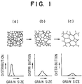
- Fig. 1 is a view showing a growing process of crystal grains and their particle size distribution;
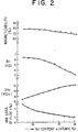
- Fig. 2 is a graph showing the relations between an Nd content of the magnet Ndα Fe93.3-αB6.5Si0.2 (by atomic %) and magnetic properties;
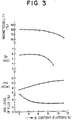
- Fig. 3 is a graph showing the relations between an Nd content of the magnet Nd12.5Fe87.3-βBβSi0.2 (by atomic %) and magnetic properties;
- Fig. 4 is a graph showing the demagnetization curves varying with a magnetic field intensity as a parameter;
- Fig. 5 is a graph showing the relations between an irreversible loss of flux and an exposure temperature;
- Fig. 6 is a graph showing the relations between a coercive force iHc and a heat-resisting temperature;
- Fig. 7 is a graph showing the relations between a coercive force iHc and magnetizability and an irreversible loss of flux;
- Fig. 8 is a graph showing the 4πI-H curve of the as-R.Q. magnet Nd11.8Fe80.2B6.5Nb1.5 (by atomic %);
- Fig. 9 is a graph showing the 4πI-H curve of the as-R.Q. magnet Nd12.3Fe80.2B6.5Nb1.0 (by atomic %) in Comparative Example;
- Fig. 10 is a graph showing an X-ray diffraction pattern of the magnet Nd11.8Fe80.2B6.5Nb1.5 (by atomic %);
- Fig. 11 is a graph showing an X-ray diffraction pattern of the magnet Nd12.3 Fe80.2B6.5Nb1.0 (by atomic %) in Comparative Example; and
- Fig. 12 is a graph showing the relations between a heat treatment temperature and an average crystal grain size.
- The magnet powder which may be used has a composition represented by the formula:
RaFebBcMd,
wherein R represents one or more rare earth elements including Y, M represents at least one element selected from the group consisting of Nb, W, V, Mo and Ta, and a, b, c and d are atomic % satisfying: - a: 12-15,
- b: balance,
- c: 4-8, and
- d: 10 or less.
- When R is less than 10 atomic %, the irreversible loss of flux becomes 5% or more at an ambient temperature of 140°C, and when R exceeds 15 atomic %, the residual magnetic flux density Br of the magnet becomes lower than 4.5 kG. Thus, permanent magnets having excellent magnetic properties cannot be obtained outside the R range of 12-15 atomic %. The range of R is 12-15 atomic % in order that the magnet alloy shows a remarkably improved heat resistance. Incidentally, R may be used as a mixture such as Misch metal and didymium because they are easily available. R may not be a pure rare earth element, and it may contain inevitable impurities in permissible ranges.
- With respect to B, when the B content is lower than 4 atomic %, the irreversible loss of flux of the magnet becomes 5% or more at an ambient temperature of 140°C, and when it exceeds 8 atomic %, the residual magnetic flux density Br becomes lower than 4.5 kG, thereby failing to provide permanent magnets with excellent magnetic properties.
- In order to improve the magnetizability and heat resistance (expressed by an irreversible loss of flux which is lower than 5% at an ambient temperature of 140°C, a permeance coefficient Pc=2), or to lower production costs, the rare earth-iron-boron permanent magnet alloy may contain at least one of the following additive elements. Since the improvement of the magnetizability and the heat resistance inevitably leads to the deterioration of a residual magnetic flux density Br or an irreversible loss of flux to some extent, the additive elements should be in the following amounts, if any.
- Nb:
- 3 atomic % or less,
- W:
- 3 atomic % or less,
- V:
- 3 atomic % or less,
- Mo:
- 3 atomic % or less, and
- Ta:
- 3 atomic % or less.
- The preferred amounts of the additive elements are as follows:
- Nb:
- 0.05 - 3 atomic %
- W:
- 0.05 - 3 atomic %
- V:
- 0.05 - 3 atomic %
- Mo:
- 0.05 - 3 atomic %
- Ta:
- 0.05 - 3 atomic %
- When two or more additive elements are added, the total contents of the additive elements should be at most the largest upper limit of the additive elements.
- Incidentally, besides the additive elements, the permanent magnet of the present invention may contain inevitable impurities in permissible amounts.
- It is critical in the present invention that the magnet alloy has a crystal grain size in a particular range. It has been found that in the above composition range, the crystal grain size in a particular range can provide the bonded magnet with excellent magnetizability and heat resistance. Specifically, the optimum condition is such that the average crystal grain size is 0.01-0.2 µm, and 90% or more by area of the crystal grains have a grain size of 0.2 µm or less.
- When the average crystal grain size is lower than 0.01 µm, the coercive force iHc is insufficient, and when it exceeds 0.2 µm, the crystal grains become too large, so that reverse magnetic domains may be generated, resulting in a decrease in iHc. Accordingly, the average crystal grain size should be 0.01-0.2 µm. The preferred average crystal grain size is 0.01-0.15 µm. In general, since the crystal grains grow by a heat treatment, the heat treatment conditions such as temperature should be controlled at 800°C or lower.
- Incidentally, the measurement of the crystal grain size is conducted by using a cut method or an X-ray method. In the former method, the procedure is relatively easy, but large deviations exist among measurement points, meaning that it fails to provide high measurement accuracy. On the other hand, in the latter method, high measurement accuracy can be achieved, but large crystal grains cannot be measured.
- (a) Grain counting method (cut method)
The method is essentially according to the following two methods:- Method of measuring austenite crystal grain size of steel (JIS G 0551 (1977))
- Method of measuring ferrite crystal grain size of steel (JIS G 0552 (1977))


- n:
- Number of crystal grains in a 25-mm area seen at a magnification of 100.
- M:
- Magnification of a microscope.
- L₁ (or L₂):
- Total length of one of two vertically rectangular lines (unit: mm).
- I₁ (or I₂):
- Total number of crystal grains cut by L₁ or L₂.
- n' is compared with a standard grain size shown by JIS G 0551 or JIS G 0552 to determine an average crystal grain size.
- (b) X-ray method according to Scherrer's formula:


- t:
- Size of crystal grain.
- K:
- Scherrer constant.
- λ:
- Wavelength of X-ray.
- θB:
- Bragg's angle.
- B:
- Broadening of X-ray diffraction peak (real value).
- Bm:
- Broadening of X-ray diffraction peak (measured value).
- B₀:
- Broadening of X-ray diffraction peak (due to apparatus, etc.).
- The size of crystal grain is determined from t. By this method, a thickness in perpendicular to a plane (h, k, ℓ) can be measured by measuring the broadening of a diffraction peak of a plane (h, k, ℓ).
- In the present invention, the crystal grain distribution should be such that 90% or more of the crystal grains have a grain size of 0.2 µm or less.
- When the crystal grains having a grain size of 0.2 µm or less are less than 90%, coarse crystal grains are subjected to reversal of magnetization at a high temperature, thereby showing poor heat resistance. The optimum results can be obtained when the magnet is constituted by uniform fine crystal grains having a grain size of 0.2 µm or less.
- Fig. 1 schematically shows the growth of the crystal grain distributions. Fig. 1 (a) shows the alloy structure of the magnet of the present invention, in which fine crystal grains far smaller than the critical size of 0.3 µm for single domain particles are uniformly distributed with a small standard deviation σ. In this case, the reversal of magnetization is unlikely, because the rotation of the single magnetic domains is prevented by the crystal grain boundaries. Fig. 1 (b) shows the alloy structure in which fine crystal grains and coarse crystal grains coexist. The coarse crystal grains contain a plurality of magnetic domains. In this case, the reversal of magnetization easily takes place by the movement of domain walls. Accordingly, irreversible loss of flux takes place by elevating the ambient temperature. Fig. 1 (c) shows the alloy structure of the conventional magnet which is occupied by coarse crystal grains. The reversal of magnetization takes place extremely easily by the movement of domain walls, resulting in large irreversible loss of flux.
- In the production of the magnet alloy, a melt of rare earth-iron-boron permanent magnet alloy having the above composition is rapidly quenched to provide a thin ribbon, powder or flakes, which have an initial coercive force iHc of 2000 Oe or less, preferably 1000 Oe or less at room temperature. When the coercive force of such thin ribbon, powder or flakes is 2000 Oe or less, the magnetizability and heat resistance of the magnet are not deteriorated even by a heat treatment for making uniform the crystal grain size and the residual magnetic flux density Br.
- For this purpose, the thin ribbon, powder or flakes are produced under the above rapid-quenching conditions.
- The rapid quenching method which may be conducted on a melt of a rare earth-iron-boron permanent magnet alloy includes a centrifugal rapid-quenching method, in which an alloy melt is ejected onto an inner wall of a cooling drum rotating at a high speed to rapidly solidify the alloy melt, a single roll method in which an alloy melt is ejected onto a rotating roll; a double roll method in which an alloy melt is ejected into a gap between two drums rotating at a high speed, etc. In the production of powder, an atomizing method can be used, and the flakes can be produced by pulverizing the above thin ribbons, etc.
- Next, a heat treatment at 800°C or lower is conducted to provide the magnet alloy with good magnetizability and heat resistance free from unevenness of a crystal grain size and a residual magnetic flux density Br. The preferred temperature of the heat treatment is 550-800°C. When it is lower than 550°C, the heat-treated magnet alloy is mainly composed of an isotropic, amorphous phase originally obtained by a rapid quenching method, showing poor magnetic properties. On the other hand, when it exceeds 800°C, fine crystal grains generated by the heat treatment become too large, and the precipitation of heterogeneous phase takes place, resulting in a decrease in a coercive force iHc.
- The heat-treated magnet alloy is then pulverized.
- With respect to the average particle size of magnetic powder, when it is less than 1 µm, unnecessary oxidation and deterioration may be caused. On the other hand, when the average particle size exceeds 1000 µm, the moldability, feedability, packability and compressibility in forming of the bonded magnet becomes poor.
- The magnet powder is then blended with a binder to provide the bonded magnet.
- The binder is usually a resin such as an epoxy resin, nylon, etc. When better heat resistance is required, metal binders may be used. In this case, rotation forging is effective.
- When the binder content in the resulting bonded magnet is less than 5 volume %, the bonded magnet has a poor mechanical strength, and when it exceeds 40 volume %, the bonded magnet shows poor magnetic properties because of an increase in a non-magnetic portion.
- The bonded rapid quench magnet having excellent magnetizability and heat resistance according to the present invention can be used for permanent magnet-type motors having extremely improved heat resistance.
- The present invention will be explained in further detail by the following Examples and comparative examples.
- A mother alloy of Nd₁₅Fe₇₆B6.5Co2.5 (by atomic %) was prepared by arc melting, and ejected through a quartz nozzle in an Ar atmosphere at an atmospheric pressure while being subjected to high-frequency melting, to produce about 200 g of a thin ribbon of 5 mm in width and about 40 µm in thickness by a single roll method (wheel surface velocity: 30 m/sec). The resulting thin ribbon in an as-rapidly quenched (as-R.Q.) state had an initial coercive force iHc of 300 Oe.
- Next, the thin ribbon was placed in a vacuum furnace heated at 650°C for 1 hour, and then taken out of the furnace and rapidly quenched by blowing Ar. The heat-treated thin ribbon had a coercive force iHc of 12.5 kOe. The heat-treated magnet alloy had an average crystal grain size of 0.09 µm, and 90% or more of the crystal grains had a grain size (diameter) of 0.15 µm or less when observed by a scanning-type electron microscope.
- The heat-treated thin ribbon was pulverized to -30 mesh and then blended with an epoxy resin to provide a bonded rapid quench magnet.
- This bonded magnet was magnetized at 20 kOe and evaluated with respect to magnetic properties, heat resistance and magnetizability. As a result, it was found that this bonded magnet had a residual magnetic flux density Br of 5.3 kG, a coercive force iHc of 12.5 kOe, and an irreversible loss of flux of 2.4% at an ambient temperature of 140°C and at a permeance coefficient Pc of 2.0.
- A mother alloy of Nd12.5Fe₇₉B6.5Nb₂ (by atomic %) was prepared by arc melting, and ejected through a quartz nozzle in an Ar atmosphere at an atmospheric pressure while being subjected to high-frequency melting, to produce about 200 g of a thin ribbon of 5 mm in width and about 30 µm in thickness by a single roll method (wheel surface velocity: 30 m/sec). The resulting thin ribbon in an as-rapidly quenched (as-R.Q.) state had an initial coercive force 1Hc of 120 Oe.
- Next, the thin ribbon was placed in a vacuum furnace heated at 700°C for 1 hour, and then taken out of the furnace and rapidly quenched by blowing Ar. The heat-treated thin ribbon had a coercive force iHc of 16.0 kOe. The heat-treated magnet alloy had an average crystal grain size of 0.075 µm, and 90% or more of the crystal grains had a grain size (diameter) of 0.10 µm or less when observed by a scanning-type electron microscope.
- The heat-treated thin ribbon was pulverized to -30 mesh and then blended with an epoxy resin to provide a bonded rapid quench magnet.
- This bonded magnet was magnetized at 25 kOe and evaluated with respect to magnetic properties, heat resistance and magnetizability. As a result, it was found that this bonded magnet had a residual magnetic flux density Br of 5.1 kG, a coercive force iHc of 16.0 kOe, and an irreversible loss of flux of 0.5% at an ambient temperature of 140°C and at a permeance coefficient Pc of 2.0.
- Fig. 4 is a graph showing the demagnetization curves varying with a magnetic field intensity Ha as a parameter. It is clear from Fig. 4 that this bonded magnet shows excellent magnetizability because its coercive force iHc is lower than 20 kOe when magnetized at a magnetic field intensity of 30 kOe.
- A mother alloy of Nd12.5Fe79.5B6.5Nb1.5 (by atomic %) was prepared by arc melting, and ejected through a quartz nozzle in an Ar atmosphere at an atmospheric pressure while being subjected to high-frequency melting, to produce about 200 g of a thin ribbon of 5 mm in width and about 30 µm in thickness by a single roll method (wheel surface velocity: 30 m/sec). The resulting thin ribbon in an as-rapidly quenched (as-R.Q.) state had an initial coercive force iHc of 300 Oe.
- Next, the thin ribbon was placed in a vacuum furnace heated at 660°C for 1 hour, and then taken out of the furnace and rapidly quenched by blowing Ar. The heat-treated thin ribbon had a coercive force iHc of 14.0 kOe. The heat-treated magnet alloy had an average crystal grain size of 0.07 µm, and 90% or more of the crystal grains had a grain size (diameter) of 0.12 µm or less when observed by a scanning-type electron microscope.
- The heat-treated thin ribbon was pulverized to a particle size of 500 µm. The magnet powder was blended with an epoxy resin to provide a bonded rapid quench magnet.
- This bonded magnet was magnetized at 19.5 kOe and evaluated with respect to magnetic properties, heat resistance and magnetizability. Incidentally, samples were prepared such that they had a permeance coefficient Pc of 2.0.
- R-Fe-B magnets having various compositions were prepared by the known methods.
- Fig. 5 is a graph showing the relations between an irreversible loss of flux and an ambient temperature in the present invention and Comparative Examples. In Fig. 5, "A" shows the magnet of Example 13, "B" shows a conventional rapid quench magnet (Comparative Example 1), and "C" shows an anisotropic bonded magnet (Comparative Example 2). It is clear from Fig. 5 that the bonded magnet (A) produced by the rapid-quenching method according to the present invention had extremely good heat resistance.
- In Comparative Example 1, magnetically isotropic bonded magnet (B) was produced according to a method shown in Example 1 of Japanese Patent Laid-Open No. 59-211549 as a conventional rapid quenching method. Incidentally, the alloy composition was 20% Nd, 76% Fe and 4% B by atomic %, which is outside the range of the present invention in Nd.
- In Comparative Example 2, magnetically anisotropic bonded magnet (C) was produced according to a method shown in Example 1 of Japanese Patent Laid-Open No. 63-232301. Incidentally, the alloy composition was 17% Nd, 75% Fe and 8% B by atomic %, which is outside the range of the present invention in Nd.
- In Comparative Example 3, sintered magnet ("D" in Fig. 6) was produced according to a method shown in Example of Japanese Patent Publication No. 61-34342. Incidentally, the alloy composition was 14% Nd, 79% Fe and 7% B by atomic %. Although the alloy composition of the magnet is within the range of the present invention, the magnet of Comparative Example 3 is extremely different from that of Example 13 with respect to an average crystal grain size. In addition, in the sintered magnet (D), Nd-rich phases are trapped between dendrites contained in an ingot, so that this structure remains in the final product. On the other hand, in the rapid quenching method according to the present invention, the Nd-phases are uniformly and finely dispersed in the magnet structure.
- Samples having various coercive forces were produced in the same manner as in Example 3. For comparison, the same magnets (B-D) as in Comparative Examples 1-3 were also produced. They were evaluated with respect to heat-resisting temperature varying with a coercive force. The results are shown in Fig. 6. Here, the heat-resisting temperature is defined as an ambient temperature at which the irreversible loss of flux becomes 5% at a permeance coefficient of 2. It is clear from Fig. 6 that the bonded magnet of this Example shows extremely high heat-resisting temperature despite its low coercive force.
- Fig. 7 shows the relations between a coercive force iHc and magnetizability and an irreversible loss of flux with respect to the magnet of this Example. It is clear from Fig. 7 that the isotropic bonded magnet of this Example shows good magnetizability as its coercive force iHc decreases. Thus, since the coercive force iHc can be decreased in the present invention, the bonded magnet can have both satisfactory magnetizability and heat resistance.
- In order to examine influences of the shapes of the rapidly quenched thin flakes on heat resistance, the as-R.Q. thin flakes were examined with respect to magnetic properties, X-ray diffraction pattern.
- Samples (No. 1-4, 5-8) having various formulations shown in Table 1 were melted in a vacuum furnace and then formed into thin flakes under the conditions shown in Table 2. Sample Nos. 1-4 were rapidly quenched at the wheel surface velocity of 22 m/sec, and Sample Nos. 5-8 were rapidly quenched at the wheel surface velocity of 9 m/sec.
- Next, to prevent oxidation during the heat treatment, each sample was wrapped in an Nb foil and a stainless steel (SUS) foil, and subjected to a heat treatment at 650°C for 2 hours in vacuum.
- As-R.Q. thin flakes and heat-treated thin flakes were used to prepare bonded magnets by the following method.
- In the first step, thin flakes were crashed into -32 mesh powder, and then 95 weight % of magnet powder, 3.5 weight % of an epoxy resin, 0.75 weight % of a hardening agent and 0.75 weight % of alcohol were mixed, and subjected to compression molding. The resulting moldings were then hardened.
- The isotropic bonded magnets thus produced were measured with respect to an irreversible loss of flux. After that, each sample was magnetized at 25 kOe to measure its magnetic properties. Similarly, bonded magnet samples produced by using as-R.Q. magnet powder were magnetized at 25 kOe to measure their magnetic properties. The magnetic properties were determined from 4πI-H curves produced by an automatic magnetic flux meter.
- With respect to the samples, their crystal grain sizes were measured by an X-ray method (powder method). Each sample was produced by pulverizing the as-R.Q. thin flakes to -32 mesh, mixing them with ethylene glycol and then applying the mixture onto a X-ray glass holder.
- Table 1 shows the formulations (by atomic %) of the magnets, coercive forces of the as-R.Q. magnet alloys, irreversible loss of flux and magnetic properties of the heat-treated bonded magnets.
- In Table 1, Sample Nos. 1-4 show good heat resistance, and Sample Nos. 5-8 show poor heat resistance. Fig. 8 shows a 4πI-H curve of Sample No. 1 (as R.Q.) having good heat resistance, and Fig. 9 shows a 4πI-H curve of Sample No. 6 (as R.Q.) having poor heat resistance.
- It is clear from Figs. 8 and 9 that the sample having good heat resistance does not substantially have a coercive force iHc in an as-R.Q. state, and that its initial magnetization curve is steep. On the other hand, the sample having poor heat resistance has a relatively large coercive force in an as-R.Q. state, and shows a smaller rise in an initial magnetization curve.
- As shown in Fig. 10, the sample having good heat resistance does not show X-ray diffraction peaks, while the sample having poor heat resistance shows X-ray diffraction peaks assignable to Nd₂Fe₁₄B as shown in Fig. 11. This means that the sample having good heat resistance is almost amorphous in an as-R.Q. state, while the sample having poor heat resistance contains crystalline phases in an as-R.Q. state.

Table 2 Wheel Surface Velocity Material of Roll Sample Nos. 5-8 9 m/sec Beryllium-Copper Alloy Sample Nos. 1-4 25 m/sec Copper Roll Provided with 1 mm-Thick Hard Chromium Plating - A rapidly quenched thin ribbon was produced from an alloy melt of Nd12.5Fe₇₉B6.5Nb₂ (by atomic %) by the method shown in Example 5 using a copper roll.
- The thin ribbon was subjected to a heat treatment at a temperature from 500°C to 850°C stepwise by 50°C to examine the relations between the heat treatment temperature and the average crystal grain size. The results are shown in Fig. 12. At 500°C, good magnetic properties cannot be obtained because the magnet alloy structure was mostly occupied by an amorphous phase. When the heat-treating temperature exceeds 800°C, the crystal grains became undesirably coarse, and heterogeneous phases were precipitated. Incidentally, the grain size was determined by the cut method.
- The alloy magnet powder prepared in Example 5 was mixed with 8 volume % of a polyamide resin to produce a bonded magnet of 8 mm in outer diameter and 5.5 mm in inner diameter. The bonded magnet was provided with 10 magnetic poles with the same interval to provide a rotor for a pulse motor. For comparison, a rotor having the same structure was produced from Nd₁₃Fe₈₁B₆ (by atomic %) to provide a pulse motor.
- The average crystal grain size was 0.06 µm in this Example and 0.6 µm in the comparative magnet. In the comparative case, the average crystal grain size is larger than this Example by one order, since the comparative magnet does not contain Nb, etc. which function to generate nuclei for crystallization, and since its cooling speed is not sufficiently high due to use of the conventional roll, resulting in high iHc after rapid quenching. In other words, the crystal grains grew more than a critical size of a single magnetic domain.
- Table 3 shows the performance of pulse motors. It is clear from Table 3 that the pulse motor of the present invention shows high torque not only at room temperature but also after exposed at 150°C.
Table 3 (unit: g·cm) at Room Temp. After Exposed at 150° C Present Invention 106 100 Comparative Magnet 83 61 - As described in detail above, according to the present invention, magnets having excellent magnetizability and heat resistance without deteriorating their magnetic properties can be obtained. Since the magnets of the present invention have good magnetizability, they can be magnetized at a relatively low magnetic field intensity. Accordingly, the magnets of the present invention can be utilized in various applications such as assembled magnets, ring magnets, etc.
- In addition, since the magnets of the present invention have good heat resistance, they can be used in a high-temperature environment. By using the magnets of the present invention, permanent magnet-type motors, such as motors for automobiles, stepping motors, brushless motors, etc. can be obtained.
Claims (7)
- A bonded magnet comprising a rapid quench magnet powder which is magnetically isotropic and composed of an R-Fe-B-M magnet alloy, wherein R represents at least one rare earth element including Y in the range of 12-15 atomic %, B represents boron in the range of 4-8 atomic %, Fe represents iron in a balance amount, 20% or less of which may be substituted by Co, and M represents at least one element selected from the group consisting of Nb, W, V, Mo and Ta in an amount of 10 atomic % or less, and has an average crystal grain size of 0.01-0.2 µm or 0.2 µm or less in 90% or more by area of said crystal grains, and an average particle size of 1-1000 µm; and 5-40 volume % of a binder.
- The bonded rapid quench magnet according to claim 1, wherein said magnet alloy has an average crystal grain size of 0.01-0.15 µm.
- A magnet according to claim 1 or 2, wherein the amount of M is in the range of 0.05 to 3 atomic %.
- A method of producing a bonded magnet according to claim 1, comprising the steps of:a) preparing an alloy melt having a composition represented by the formula:
RaFebBcMd,
wherein R represents one or more rare earth elements including Y, M represents at least one element selected from the group consisting of Nb, W, V, Mo and Ta, 20% or less of Fe may be substituted by Co, and a, b, c and d are atomic % satisfying:a: 12-15,b: balance,c: 4-8, andd: 10 or less;b) ejecting said alloy melt onto a roll rotating at 10-40 m/sec to produce a thin ribbon substantially composed of an amorphous phase and having an average thickness of 10-60 µm and an initial coercive force of 2000 Oe or less by a rapid quenching method;c) subjecting said thin ribbon to a heat treatment at a temperature of 550-800°C;d) pulverizing the heat-treated thin ribbon to an average particle size of 1-1000 µm; ande) blending the resulting magnet powder with 5-40 volume % of a binder. - The method according to claim 4, wherein said thin ribbon has an initial coercive force of 1000 Oe or less.
- The method of claim 4 or 5, wherein d is in the range of 0.05 to 3 atomic %.
- A permanent magnet-type motor using a permanent magnet according to any of claims 1 to 3 in a stator and/or a rotor.
Applications Claiming Priority (6)
| Application Number | Priority Date | Filing Date | Title |
|---|---|---|---|
| JP25045288 | 1988-10-04 | ||
| JP250452/88 | 1988-10-04 | ||
| JP3039/89 | 1989-01-10 | ||
| JP303989 | 1989-01-10 | ||
| JP21460689 | 1989-08-21 | ||
| JP214606/89 | 1989-08-21 |
Publications (3)
| Publication Number | Publication Date |
|---|---|
| EP0362812A2 EP0362812A2 (en) | 1990-04-11 |
| EP0362812A3 EP0362812A3 (en) | 1991-04-24 |
| EP0362812B1 true EP0362812B1 (en) | 1996-01-24 |
Family
ID=27275635
Family Applications (1)
| Application Number | Title | Priority Date | Filing Date |
|---|---|---|---|
| EP89118389A Expired - Lifetime EP0362812B1 (en) | 1988-10-04 | 1989-10-04 | Bonded isotropic R-Fe-B-magnet and method for making it |
Country Status (4)
| Country | Link |
|---|---|
| US (1) | US5449417A (en) |
| EP (1) | EP0362812B1 (en) |
| JP (1) | JP2843379B2 (en) |
| DE (1) | DE68925506T2 (en) |
Families Citing this family (30)
| Publication number | Priority date | Publication date | Assignee | Title |
|---|---|---|---|---|
| FR2655355B1 (en) * | 1989-12-01 | 1993-06-18 | Aimants Ugimag Sa | ALLOY FOR PERMANENT MAGNET TYPE FE ND B, SINTERED PERMANENT MAGNET AND PROCESS FOR OBTAINING SAME. |
| US5725792A (en) * | 1996-04-10 | 1998-03-10 | Magnequench International, Inc. | Bonded magnet with low losses and easy saturation |
| JP3299887B2 (en) * | 1996-06-27 | 2002-07-08 | 明久 井上 | Hard magnetic material |
| US5872501A (en) * | 1996-07-07 | 1999-02-16 | Toda Kogyo Corporation | Rare earth bonded magnet and rare earth-iron-boron type magnet alloy |
| DE69819953T2 (en) * | 1997-03-25 | 2004-11-11 | Alps Electric Co., Ltd. | Fe-based hard magnetic alloy with a super-cooled span |
| US6332933B1 (en) | 1997-10-22 | 2001-12-25 | Santoku Corporation | Iron-rare earth-boron-refractory metal magnetic nanocomposites |
| US6478890B2 (en) * | 1997-12-30 | 2002-11-12 | Magnequench, Inc. | Isotropic rare earth material of high intrinsic induction |
| US6183572B1 (en) * | 1997-12-30 | 2001-02-06 | Magnequench International, Inc. | Isotropic rare earth material of high intrinsic induction |
| WO2000003403A1 (en) * | 1998-07-13 | 2000-01-20 | Santoku America Inc. | High performance iron-rare earth-boron-refractory-cobalt nanocomposites |
| WO2000033325A1 (en) * | 1998-12-03 | 2000-06-08 | Institut für Festkörper- und Werkstofforschung Dresden e.V. | Hard magnetic alloy and casting mould produced therewith |
| US6302972B1 (en) * | 1998-12-07 | 2001-10-16 | Sumitomo Special Metals Co., Ltd | Nanocomposite magnet material and method for producing nanocomposite magnet |
| JP3186746B2 (en) | 1998-12-28 | 2001-07-11 | セイコーエプソン株式会社 | Magnet powder and isotropic rare earth bonded magnet |
| JP3275882B2 (en) * | 1999-07-22 | 2002-04-22 | セイコーエプソン株式会社 | Magnet powder and isotropic bonded magnet |
| US6500277B1 (en) * | 1999-06-11 | 2002-12-31 | Seiko Epson Corporation | Magnetic powder and isotropic bonded magnet |
| JP2001332410A (en) * | 2000-05-22 | 2001-11-30 | Seiko Epson Corp | Magnet powder, its manufacturing method, and bond magnet |
| EP1338359B1 (en) * | 2000-10-06 | 2007-11-21 | Santoku Corporation | Process for producing, through strip casting, raw alloy for nanocomposite type permanent magnet |
| US20040079445A1 (en) * | 2002-10-24 | 2004-04-29 | Zhongmin Chen | High performance magnetic materials with low flux-aging loss |
| EP2043111A1 (en) * | 2007-09-10 | 2009-04-01 | Nissan Motor Co., Ltd. | Rare earth permanent magnetic alloy and producing method thereof |
| US8821650B2 (en) * | 2009-08-04 | 2014-09-02 | The Boeing Company | Mechanical improvement of rare earth permanent magnets |
| KR20140072047A (en) | 2011-08-17 | 2014-06-12 | 리전츠 오브 더 유니버시티 오브 미네소타 | Iron nitride permanent magnet and technique for forming iron nitride permanent magnet |
| WO2014124135A2 (en) | 2013-02-07 | 2014-08-14 | Regents Of The University Of Minnesota | Iron nitride permanent magnet and technique for forming iron nitride permanent magnet |
| CA2916483C (en) | 2013-06-27 | 2017-02-28 | Regents Of The University Of Minnesota | Iron nitride materials and magnets including iron nitride materials |
| BR112016022561A2 (en) | 2014-03-28 | 2017-08-15 | Univ Minnesota | IRON NITRIDE MAGNETIC MATERIAL INCLUDING COATED NANOPARTICLES |
| US9994949B2 (en) | 2014-06-30 | 2018-06-12 | Regents Of The University Of Minnesota | Applied magnetic field synthesis and processing of iron nitride magnetic materials |
| CA2957732A1 (en) | 2014-08-08 | 2016-02-11 | Regents Of The University Of Minnesota | Forming iron nitride hard magnetic materials using chemical vapor deposition or liquid phase epitaxy |
| WO2016022711A1 (en) | 2014-08-08 | 2016-02-11 | Regents Of The University Of Minnesota | Multilayer iron nitride hard magnetic materials |
| US10072356B2 (en) | 2014-08-08 | 2018-09-11 | Regents Of The University Of Minnesota | Magnetic material including α″-Fe16(NxZ1-x)2 or a mixture of α″-Fe16Z2 and α″-Fe16N2, where Z includes at least one of C, B, or O |
| US10002694B2 (en) | 2014-08-08 | 2018-06-19 | Regents Of The University Of Minnesota | Inductor including alpha″-Fe16Z2 or alpha″-Fe16(NxZ1-x)2, where Z includes at least one of C, B, or O |
| US20180122570A1 (en) * | 2016-10-27 | 2018-05-03 | Ut-Battelle, Llc | Bonded permanent magnets produced by big area additive manufacturing |
| CN113201700B (en) * | 2021-04-26 | 2022-05-10 | 辽宁科技大学 | Fe-based block amorphous soft magnetic material with high formation energy and preparation method thereof |
Family Cites Families (13)
| Publication number | Priority date | Publication date | Assignee | Title |
|---|---|---|---|---|
| US4402770A (en) * | 1981-10-23 | 1983-09-06 | The United States Of America As Represented By The Secretary Of The Navy | Hard magnetic alloys of a transition metal and lanthanide |
| JPS59163802A (en) * | 1983-03-08 | 1984-09-14 | Sumitomo Special Metals Co Ltd | Permanent magnet material |
| CA1316375C (en) * | 1982-08-21 | 1993-04-20 | Masato Sagawa | Magnetic materials and permanent magnets |
| JPS5964733A (en) * | 1982-09-27 | 1984-04-12 | Sumitomo Special Metals Co Ltd | Permanent magnet |
| JPS5946008A (en) * | 1982-08-21 | 1984-03-15 | Sumitomo Special Metals Co Ltd | Permanent magnet |
| US4851058A (en) * | 1982-09-03 | 1989-07-25 | General Motors Corporation | High energy product rare earth-iron magnet alloys |
| DE3379131D1 (en) * | 1982-09-03 | 1989-03-09 | Gen Motors Corp | Re-tm-b alloys, method for their production and permanent magnets containing such alloys |
| EP0106948B1 (en) * | 1982-09-27 | 1989-01-25 | Sumitomo Special Metals Co., Ltd. | Permanently magnetizable alloys, magnetic materials and permanent magnets comprising febr or (fe,co)br (r=vave earth) |
| CA1216623A (en) * | 1983-05-09 | 1987-01-13 | John J. Croat | Bonded rare earth-iron magnets |
| ATE68626T1 (en) * | 1986-01-10 | 1991-11-15 | Ovonic Synthetic Materials | PERMANENT MAGNETIC ALLOY. |
| JP2530641B2 (en) * | 1986-03-20 | 1996-09-04 | 日立金属株式会社 | Magnetically anisotropic bonded magnet, magnetic powder used therefor, and method for producing the same |
| EP0242187B1 (en) * | 1986-04-15 | 1992-06-03 | TDK Corporation | Permanent magnet and method of producing same |
| JPS62261102A (en) * | 1986-05-07 | 1987-11-13 | Hitachi Metals Ltd | Bonded magnet for starter motor |
-
1989
- 1989-10-04 JP JP1259514A patent/JP2843379B2/en not_active Expired - Lifetime
- 1989-10-04 EP EP89118389A patent/EP0362812B1/en not_active Expired - Lifetime
- 1989-10-04 DE DE68925506T patent/DE68925506T2/en not_active Expired - Fee Related
-
1994
- 1994-05-13 US US08/242,050 patent/US5449417A/en not_active Expired - Lifetime
Non-Patent Citations (1)
| Title |
|---|
| servomotors" * |
Also Published As
| Publication number | Publication date |
|---|---|
| DE68925506D1 (en) | 1996-03-07 |
| EP0362812A3 (en) | 1991-04-24 |
| US5449417A (en) | 1995-09-12 |
| EP0362812A2 (en) | 1990-04-11 |
| JPH03227502A (en) | 1991-10-08 |
| JP2843379B2 (en) | 1999-01-06 |
| DE68925506T2 (en) | 1996-09-19 |
Similar Documents
| Publication | Publication Date | Title |
|---|---|---|
| EP0362812B1 (en) | Bonded isotropic R-Fe-B-magnet and method for making it | |
| EP0261579B1 (en) | A method for producing a rare earth metal-iron-boron permanent magnet by use of a rapidly-quenched alloy powder | |
| CN103036323B (en) | Permanent magnet and motor and generator using the same | |
| EP0242187A1 (en) | Permanent magnet and method of producing same | |
| WO2015020183A1 (en) | R-t-b type sintered magnet, and motor | |
| JP2751109B2 (en) | Sintered permanent magnet with good thermal stability | |
| EP2447960A1 (en) | Anisotropic rare earth sintered magnet and making method | |
| EP2733711B1 (en) | Permanent magnet, and motor and power generator using the same | |
| EP0657899B1 (en) | Iron-based permanent magnet alloy powders for resin bonded magnets and magnets made therefrom | |
| WO2021048916A1 (en) | Rare earth magnet alloy, production method for same, rare earth magnet, rotor, and rotating machine | |
| JP2727507B2 (en) | Permanent magnet and manufacturing method thereof | |
| EP1018751B1 (en) | Thin plate magnet having microcrystalline structure | |
| US6338761B1 (en) | Iron-based permanent magnets and their fabrication as well as iron-based permanent magnet alloy powders for permanent bonded magnets and iron-based bonded magnets | |
| JPH10163056A (en) | Manufacture of magnet | |
| EP0386286B1 (en) | Rare earth iron-based permanent magnet | |
| JP3003979B2 (en) | Permanent magnet and method for manufacturing the same | |
| CN117751414A (en) | Rare earth sintered magnet, method for producing rare earth sintered magnet, rotor, and rotary machine | |
| CN115398574B (en) | Rare earth sintered magnet, method for producing rare earth sintered magnet, rotor, and rotary machine | |
| JP3519443B2 (en) | Permanent magnet alloy powder and method for producing the same | |
| EP0229946B1 (en) | Permanent magnetic alloy | |
| JPH113812A (en) | Permanent magnet material and bonded magnet | |
| JP2966169B2 (en) | Rare earth magnet, alloy powder for rare earth magnet and method for producing the same | |
| JP2999648B2 (en) | Rare earth magnet, rare earth magnet alloy powder and method for producing the same | |
| JPH10130796A (en) | Production of fine crystal permanent magnet alloy and isotropic permanent magnet powder | |
| JP3547016B2 (en) | Rare earth bonded magnet and method of manufacturing the same |
Legal Events
| Date | Code | Title | Description |
|---|---|---|---|
| PUAI | Public reference made under article 153(3) epc to a published international application that has entered the european phase |
Free format text: ORIGINAL CODE: 0009012 |
|
| AK | Designated contracting states |
Kind code of ref document: A2 Designated state(s): DE |
|
| 17P | Request for examination filed |
Effective date: 19901220 |
|
| PUAL | Search report despatched |
Free format text: ORIGINAL CODE: 0009013 |
|
| AK | Designated contracting states |
Kind code of ref document: A3 Designated state(s): DE |
|
| 17Q | First examination report despatched |
Effective date: 19930312 |
|
| GRAA | (expected) grant |
Free format text: ORIGINAL CODE: 0009210 |
|
| AK | Designated contracting states |
Kind code of ref document: B1 Designated state(s): DE |
|
| REF | Corresponds to: |
Ref document number: 68925506 Country of ref document: DE Date of ref document: 19960307 |
|
| PLBE | No opposition filed within time limit |
Free format text: ORIGINAL CODE: 0009261 |
|
| STAA | Information on the status of an ep patent application or granted ep patent |
Free format text: STATUS: NO OPPOSITION FILED WITHIN TIME LIMIT |
|
| 26N | No opposition filed | ||
| PGFP | Annual fee paid to national office [announced via postgrant information from national office to epo] |
Ref country code: DE Payment date: 20011022 Year of fee payment: 13 |
|
| PG25 | Lapsed in a contracting state [announced via postgrant information from national office to epo] |
Ref country code: DE Free format text: LAPSE BECAUSE OF NON-PAYMENT OF DUE FEES Effective date: 20030501 |