JP6076894B2 - ガス成分濃度分布測定装置及び排ガス脱硝システム - Google Patents
ガス成分濃度分布測定装置及び排ガス脱硝システム Download PDFInfo
- Publication number
- JP6076894B2 JP6076894B2 JP2013273585A JP2013273585A JP6076894B2 JP 6076894 B2 JP6076894 B2 JP 6076894B2 JP 2013273585 A JP2013273585 A JP 2013273585A JP 2013273585 A JP2013273585 A JP 2013273585A JP 6076894 B2 JP6076894 B2 JP 6076894B2
- Authority
- JP
- Japan
- Prior art keywords
- laser
- gas
- laser light
- exhaust gas
- concentration distribution
- Prior art date
- Legal status (The legal status is an assumption and is not a legal conclusion. Google has not performed a legal analysis and makes no representation as to the accuracy of the status listed.)
- Active
Links
- QGZKDVFQNNGYKY-UHFFFAOYSA-N Ammonia Chemical compound N QGZKDVFQNNGYKY-UHFFFAOYSA-N 0.000 claims description 163
- 239000007789 gas Substances 0.000 claims description 125
- 229910021529 ammonia Inorganic materials 0.000 claims description 81
- MWUXSHHQAYIFBG-UHFFFAOYSA-N Nitric oxide Chemical compound O=[N] MWUXSHHQAYIFBG-UHFFFAOYSA-N 0.000 claims description 54
- 238000005259 measurement Methods 0.000 claims description 50
- 238000002485 combustion reaction Methods 0.000 claims description 17
- 239000003638 chemical reducing agent Substances 0.000 claims description 15
- 239000003054 catalyst Substances 0.000 claims description 13
- 239000000203 mixture Substances 0.000 claims description 8
- 238000010521 absorption reaction Methods 0.000 claims description 5
- 239000013307 optical fiber Substances 0.000 claims description 4
- UGFAIRIUMAVXCW-UHFFFAOYSA-N Carbon monoxide Chemical compound [O+]#[C-] UGFAIRIUMAVXCW-UHFFFAOYSA-N 0.000 claims 1
- 239000003546 flue gas Substances 0.000 claims 1
- 238000002347 injection Methods 0.000 description 19
- 239000007924 injection Substances 0.000 description 19
- 238000001514 detection method Methods 0.000 description 6
- 238000010586 diagram Methods 0.000 description 6
- 239000000428 dust Substances 0.000 description 6
- 230000005540 biological transmission Effects 0.000 description 5
- 238000005070 sampling Methods 0.000 description 5
- 239000004065 semiconductor Substances 0.000 description 5
- 238000004847 absorption spectroscopy Methods 0.000 description 4
- AKEJUJNQAAGONA-UHFFFAOYSA-N sulfur trioxide Chemical compound O=S(=O)=O AKEJUJNQAAGONA-UHFFFAOYSA-N 0.000 description 4
- 230000003287 optical effect Effects 0.000 description 3
- 239000000126 substance Substances 0.000 description 3
- 238000002834 transmittance Methods 0.000 description 3
- IJGRMHOSHXDMSA-UHFFFAOYSA-N Atomic nitrogen Chemical compound N#N IJGRMHOSHXDMSA-UHFFFAOYSA-N 0.000 description 2
- 230000000903 blocking effect Effects 0.000 description 2
- 238000004891 communication Methods 0.000 description 2
- 238000001739 density measurement Methods 0.000 description 2
- 239000000446 fuel Substances 0.000 description 2
- 238000000034 method Methods 0.000 description 2
- 239000004071 soot Substances 0.000 description 2
- 229910000530 Gallium indium arsenide Inorganic materials 0.000 description 1
- 238000002835 absorbance Methods 0.000 description 1
- 239000003463 adsorbent Substances 0.000 description 1
- 230000002238 attenuated effect Effects 0.000 description 1
- 239000010883 coal ash Substances 0.000 description 1
- 230000007423 decrease Effects 0.000 description 1
- 230000006866 deterioration Effects 0.000 description 1
- 230000000694 effects Effects 0.000 description 1
- 238000002474 experimental method Methods 0.000 description 1
- 238000010438 heat treatment Methods 0.000 description 1
- 238000009434 installation Methods 0.000 description 1
- 230000001678 irradiating effect Effects 0.000 description 1
- 230000031700 light absorption Effects 0.000 description 1
- 239000004973 liquid crystal related substance Substances 0.000 description 1
- 229910052757 nitrogen Inorganic materials 0.000 description 1
- 238000005457 optimization Methods 0.000 description 1
- 230000000644 propagated effect Effects 0.000 description 1
- XLYOFNOQVPJJNP-UHFFFAOYSA-N water Substances O XLYOFNOQVPJJNP-UHFFFAOYSA-N 0.000 description 1
Images


Landscapes
- Investigating Or Analysing Materials By Optical Means (AREA)
Description
ガスを吸引して測定用の配管に導く際、測定の高速化が困難である。
ガスを測定用の配管に引き込んだ後に濃度測定を行うことから、配管を流通しているガスと測定管に引き込まれたガスの状態(例えば、水分濃度、温度等)が異なってしまい、測定精度が低下する。
流通ガスを局所的に採取して濃度測定を行うため、局所的なガス濃度測定はできても、濃度分布を取得することができない。また、サンプリング箇所を逐次変えて濃度測定を行えば、濃度分布を取得することは可能であるが、位置毎にガスの吸引、排出が必要となり、作業が煩雑であるとともに時間がかかる。
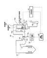
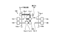
図1に示すように、本実施例に係る排ガス脱硝システムを備えたボイラ装置100は、ボイラ101からの燃焼排ガス(以下「排ガス」という)102中に還元剤(例えばアンモニア:NH3)を供給する還元剤供給手段であるアンモニア注入装置104と、還元剤が含まれた窒素酸化物(NOx)を脱硝する区画された脱硝触媒106を備えた脱硝装置105と、前記脱硝装置の出口側に設けられ、前記脱硝装置105のガス流れに直交する区画された脱硝触媒106に対応する領域における排ガス中のガス成分(NH3、NOx)濃度分布をレーザ計測手段によりアンモニア濃度を測定するガス成分濃度分布測定装置10と、を具備し、前記ガス成分濃度分布測定装置10A(10B,10C)のアンモニア濃度の計測結果より、区画された領域のアンモニアの濃度分布を求めるものである。なお、図1中、符号107は空気予熱器、108は煙突を図示する。また、図2,3,6,7中、レーザ発光部11からレーザ発光端部11aまでの部材については、斜線を付して、レーザ受光部15との差別化を図るように作図している。
なお、レーザ発光部11及びレーザ受光部15は、煙道103a,103bの外部側に配置されている。
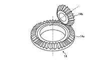
レーザ発光端部11aは、レーザ発光部11から光ファイバ19によりレーザ光を伝搬するようにしており、回転支持部14では、図4に示すような図示しない駆動部より回転される第1のかさ歯車14aとこの第1のかさ歯車14aの回転に連れまわる第2のかさ歯車14bとによりレーザ発光端部11aを360度回転している。
角度可変は、煙道103の外部より図示しない制御装置を用いて、角度を可変したり、手動により角度を可変するようにしている。
図5に示すように、レーザ発光部11から光ファイバ19を介して伝搬されたレーザ光12は、レーザ発光端部11aから出射され、対向する位置に配置されたレーザ受光端部15aに向かってレーザ光が到達し、レーザ受光部15(1)において受光される。これにより領域P1における濃度計測を実施することができる。
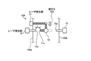
図6に示すように、排ガス102のガス流れ方向に第1のレーザ発光端部11a−1と第2のレーザ発光端部11a―2とを、所定間隔を持って設けると共に、これらに対抗する第1の受光端部15a−1と、第2の受光端部15a−2を、回転支持部14A、14Bを中心として2段以上配置するようにしている。
この際、計測領域の切欠き位置を異なるようにすることで、回転支持部14Aを中心とした同心円の複数個所でのガス組成の濃度分布を計測することができる。
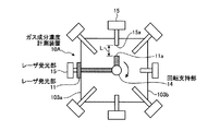
すなわち、図7中、左側の領域では、第1のレーザ発光部11Aからのレーザ光12を用いて、第1のレーザ受光部15Aで8箇所の領域(P1〜P8)の濃度分布を計測し、右側の領域では、第2のレーザ発光部11Bからのレーザ光12を用いて、第2のレーザ受光部15Bで8箇所の領域(P9〜P16)の濃度分布を計測している。
この結果、矩形の煙道103であっても、区分16点の領域(P1〜P18)のガス組成の濃度を計測することができる。
図8は、吸収分光計測の概念図である。図9は、吸収分光計測の吸収チャート図である。
レーザ光の光強度と測定対象の濃度との関係を示す関係式として、ランベルト・ベール(Lambert−Beer)の法則が知られている。
I(L)=I0exp(−kC0L) ……(1)
ここで、kは測定対象の吸光度に応じて設定される比例係数である。
I(L)=I0exp(−kC1L1) ……(2)
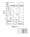
図10は、排ガス中の煤塵濃度とレーザ光透過率との関係を示す図である。
図10では、波長が1.5μmの場合、煤塵濃度が6g/Nm3程度の石炭灰中に2.0mの光路長で計測が可能であることを確認している。
よって、煤塵濃度がそれ以上の場合には、1.5m、より好適には1m前後の光路長で計測することが良好である。
図11に示すように、アンモニア注入装置104は、アンモニア供給源に接続された流路配管のアンモニア主系統22に総流量制御弁23を備えている。このアンモニア主系統22は、総流量制御弁23の下流において、ヘッダ24から分岐させた複数本(図示の例では6本)のアンモニア供給系統26を備えている。
このようにして得られた濃度測定領域の濃度分布は、例えば、制御装置20と接続された表示装置(図示略)に表示されることによって、ユーザに提示される。
よって、本装置を用いて、負荷変動等があった場合には、通常の計測回数よりも頻繁に濃度分布の計測を行うようにして、窒素酸化物の脱硝が確実になされているかを判断するようにしてもよい。
11 レーザ発光部
11a レーザ発光端部
12 レーザ光
14 回転支持部
15 レーザ受光部
15a レーザ受光端部
100 ボイラ装置
101 ボイラ
102 燃焼排ガス(排ガス)
103 煙道
104 アンモニア注入装置
105 脱硝装置
106 脱硝触媒
Claims (4)
- 燃焼排ガスが通過する煙道と、
前記燃焼排ガスのガス流れ方向と同方向に回転軸を有し、レーザ発光部からのレーザ光をガス流れと直交する方向に照射するレーザ発光端部を回転する回転支持部と、
前記レーザ発光端部と所定距離を持つと共に、前記回転支持部を中心として対向して設けられ、前記レーザ光を受光する受光端部を有する2以上のレーザ受光部と、を備えてなると共に、
前記燃焼排ガスのガス流れ方向に第1のレーザ発光端部と第2のレーザ発光端部とを、所定間隔を持って設けると共に、これらに対向する第1の受光端部と第2の受光端部とを、前記回転支持部を中心として複数段配置してなり、
前記回転支持部により前記レーザ発光端部を順次回転し、該レーザ発光端部と対向するレーザ受光端部にレーザ光を順次照射し、所定間隔を持った計測領域における燃焼排ガス中のガス組成の濃度をレーザ光の吸収により測定することを特徴とするガス成分濃度分布測定装置。 - 請求項1において、
前記レーザ発光部からのレーザ光を光ファイバによりレーザ発光端部に送光することを特徴とするガス成分濃度分布測定装置。 - 燃焼排ガス中に還元剤を供給する還元剤供給手段と、
前記還元剤が含まれた排ガス中の窒素酸化物(NOx)を脱硝する区画された脱硝触媒を備えた脱硝装置と、
前記脱硝装置の入口側又は出口側の少なくとも一方に設けられ、前記燃焼排ガス中のガス成分濃度分布を計測する請求項1又は2のガス成分濃度分布測定装置と、を具備し、
前記ガス成分濃度分布測定装置の計測結果より、ガス成分濃度分布を求めることを特徴とする排ガス脱硝システム。 - 請求項3において、
前記ガス成分がアンモニア(NH3)又は窒素酸化物(NOx)のいずれか一方又は両方であることを特徴とする排ガス脱硝システム。
Priority Applications (1)
| Application Number | Priority Date | Filing Date | Title |
|---|---|---|---|
| JP2013273585A JP6076894B2 (ja) | 2013-12-27 | 2013-12-27 | ガス成分濃度分布測定装置及び排ガス脱硝システム |
Applications Claiming Priority (1)
| Application Number | Priority Date | Filing Date | Title |
|---|---|---|---|
| JP2013273585A JP6076894B2 (ja) | 2013-12-27 | 2013-12-27 | ガス成分濃度分布測定装置及び排ガス脱硝システム |
Publications (2)
| Publication Number | Publication Date |
|---|---|
| JP2015127686A JP2015127686A (ja) | 2015-07-09 |
| JP6076894B2 true JP6076894B2 (ja) | 2017-02-08 |
Family
ID=53837730
Family Applications (1)
| Application Number | Title | Priority Date | Filing Date |
|---|---|---|---|
| JP2013273585A Active JP6076894B2 (ja) | 2013-12-27 | 2013-12-27 | ガス成分濃度分布測定装置及び排ガス脱硝システム |
Country Status (1)
| Country | Link |
|---|---|
| JP (1) | JP6076894B2 (ja) |
Families Citing this family (2)
| Publication number | Priority date | Publication date | Assignee | Title |
|---|---|---|---|---|
| KR102074728B1 (ko) * | 2017-12-19 | 2020-02-07 | 주식회사 포스코 | 가스 농도 측정 장치 |
| CN114324237B (zh) * | 2021-12-23 | 2023-09-05 | 中建材环保研究院(江苏)有限公司 | 烟气脱硝系统的氨逃逸检测装置及方法 |
Family Cites Families (5)
| Publication number | Priority date | Publication date | Assignee | Title |
|---|---|---|---|---|
| CH592931A5 (ja) * | 1976-03-18 | 1977-11-15 | Cerberus Ag | |
| JPS632145U (ja) * | 1986-06-23 | 1988-01-08 | ||
| JPH0626843Y2 (ja) * | 1988-12-15 | 1994-07-20 | 石川島播磨重工業株式会社 | ガス濃度測定装置 |
| JPH04148493A (ja) * | 1990-10-12 | 1992-05-21 | Nohmi Bosai Ltd | 煙検出装置 |
| JPH09304413A (ja) * | 1996-05-15 | 1997-11-28 | Showa Electric Wire & Cable Co Ltd | 透明流体中の異物検出方法と装置 |
-
2013
- 2013-12-27 JP JP2013273585A patent/JP6076894B2/ja active Active
Also Published As
| Publication number | Publication date |
|---|---|
| JP2015127686A (ja) | 2015-07-09 |
Similar Documents
| Publication | Publication Date | Title |
|---|---|---|
| JP5972760B2 (ja) | 排ガス脱硝システム、排ガス脱硝装置の再生方法及び排ガス脱硝装置の触媒交換方法 | |
| JP5964216B2 (ja) | 排ガス脱硝装置の触媒診断システム及び方法 | |
| CA2871816C (en) | A method for measuring temperature, molecular number density, and/or pressure of a gaseous compound from a thermal device, and a thermal system | |
| CN102022193B (zh) | 用于闭环排放物控制的系统和方法 | |
| US9243939B2 (en) | Flow volume measurement device and flow velocity measurement device | |
| ES2426107T3 (es) | Análisis de gases de combustión | |
| EP2752656A1 (en) | Fluid composition analysis mechanism, heat generation amount measurement device and power plant, and liquid composition analysis method | |
| JP5960030B2 (ja) | ガス中のガス成分濃度多点計測装置 | |
| KR101760259B1 (ko) | 추출 암모니아 연속 모니터링 시스템 | |
| JP2011127988A (ja) | ガス計測セル及びこれを用いたガス濃度計測装置 | |
| JP6000083B2 (ja) | 排ガス脱硝システム | |
| JP6076894B2 (ja) | ガス成分濃度分布測定装置及び排ガス脱硝システム | |
| JP6025504B2 (ja) | 排ガス中のガス成分濃度計測装置 | |
| JP5931557B2 (ja) | 濃度分布測定装置及び濃度分布測定方法 | |
| JP6008577B2 (ja) | 濃度測定装置及び脱硝装置 | |
| CN107764774A (zh) | 一种同时测量烟气脱硝中一氧化氮和氨气的装置及方法 | |
| JP5943687B2 (ja) | 濃度測定装置 | |
| JP6016777B2 (ja) | ガス成分濃度分布測定装置及び排ガス脱硝システム | |
| JP2014020801A (ja) | 濃度分布測定装置及び脱硝装置 | |
| JP6076895B2 (ja) | ガス成分濃度分布測定装置及び排ガス脱硝システム | |
| JP6025505B2 (ja) | ガス中のガス成分濃度計測装置 | |
| JP6076812B2 (ja) | レーザ濃度計測装置及び方法 | |
| JP2012002463A (ja) | 燃焼プラント制御装置及び燃焼プラント制御方法 | |
| JP2012167635A (ja) | 排ガス再循環装置および内燃機関システム | |
| US20130057856A1 (en) | Fluid composition analysis mechanism, calorific value measurement device, power plant and fluid composition analysis method |
Legal Events
| Date | Code | Title | Description |
|---|---|---|---|
| A621 | Written request for application examination |
Free format text: JAPANESE INTERMEDIATE CODE: A621 Effective date: 20151028 |
|
| A977 | Report on retrieval |
Free format text: JAPANESE INTERMEDIATE CODE: A971007 Effective date: 20160817 |
|
| A131 | Notification of reasons for refusal |
Free format text: JAPANESE INTERMEDIATE CODE: A131 Effective date: 20160830 |
|
| A521 | Written amendment |
Free format text: JAPANESE INTERMEDIATE CODE: A523 Effective date: 20161031 |
|
| TRDD | Decision of grant or rejection written | ||
| A01 | Written decision to grant a patent or to grant a registration (utility model) |
Free format text: JAPANESE INTERMEDIATE CODE: A01 Effective date: 20161213 |
|
| A61 | First payment of annual fees (during grant procedure) |
Free format text: JAPANESE INTERMEDIATE CODE: A61 Effective date: 20170111 |
|
| R151 | Written notification of patent or utility model registration |
Ref document number: 6076894 Country of ref document: JP Free format text: JAPANESE INTERMEDIATE CODE: R151 |