JP6066532B2 - Battery cell assembly and method for manufacturing cooling fin for battery cell assembly - Google Patents
Battery cell assembly and method for manufacturing cooling fin for battery cell assembly Download PDFInfo
- Publication number
- JP6066532B2 JP6066532B2 JP2015513885A JP2015513885A JP6066532B2 JP 6066532 B2 JP6066532 B2 JP 6066532B2 JP 2015513885 A JP2015513885 A JP 2015513885A JP 2015513885 A JP2015513885 A JP 2015513885A JP 6066532 B2 JP6066532 B2 JP 6066532B2
- Authority
- JP
- Japan
- Prior art keywords
- battery cell
- aluminum plate
- tube
- cell assembly
- rectangular aluminum
- Prior art date
- Legal status (The legal status is an assumption and is not a legal conclusion. Google has not performed a legal analysis and makes no representation as to the accuracy of the status listed.)
- Active
Links
- 238000001816 cooling Methods 0.000 title claims description 32
- 238000000034 method Methods 0.000 title claims description 13
- 238000004519 manufacturing process Methods 0.000 title claims description 10
- XAGFODPZIPBFFR-UHFFFAOYSA-N aluminium Chemical compound [Al] XAGFODPZIPBFFR-UHFFFAOYSA-N 0.000 claims description 47
- 229910052782 aluminium Inorganic materials 0.000 claims description 47
- 238000005219 brazing Methods 0.000 claims description 13
- 239000003507 refrigerant Substances 0.000 claims description 5
- 239000007788 liquid Substances 0.000 claims description 4
- 238000000151 deposition Methods 0.000 claims description 2
- 230000002093 peripheral effect Effects 0.000 claims 1
- 230000000712 assembly Effects 0.000 description 3
- 238000000429 assembly Methods 0.000 description 3
- 238000010586 diagram Methods 0.000 description 3
- 239000000853 adhesive Substances 0.000 description 2
- 230000001070 adhesive effect Effects 0.000 description 2
- 230000000694 effects Effects 0.000 description 2
- 239000000463 material Substances 0.000 description 2
- OKTJSMMVPCPJKN-UHFFFAOYSA-N Carbon Chemical compound [C] OKTJSMMVPCPJKN-UHFFFAOYSA-N 0.000 description 1
- HBBGRARXTFLTSG-UHFFFAOYSA-N Lithium ion Chemical compound [Li+] HBBGRARXTFLTSG-UHFFFAOYSA-N 0.000 description 1
- 230000004075 alteration Effects 0.000 description 1
- 230000008878 coupling Effects 0.000 description 1
- 238000010168 coupling process Methods 0.000 description 1
- 238000005859 coupling reaction Methods 0.000 description 1
- 230000007547 defect Effects 0.000 description 1
- 239000012530 fluid Substances 0.000 description 1
- 229910002804 graphite Inorganic materials 0.000 description 1
- 239000010439 graphite Substances 0.000 description 1
- 229910001416 lithium ion Inorganic materials 0.000 description 1
Images


Classifications
-
- H—ELECTRICITY
- H01—ELECTRIC ELEMENTS
- H01M—PROCESSES OR MEANS, e.g. BATTERIES, FOR THE DIRECT CONVERSION OF CHEMICAL ENERGY INTO ELECTRICAL ENERGY
- H01M10/00—Secondary cells; Manufacture thereof
- H01M10/60—Heating or cooling; Temperature control
-
- H—ELECTRICITY
- H01—ELECTRIC ELEMENTS
- H01M—PROCESSES OR MEANS, e.g. BATTERIES, FOR THE DIRECT CONVERSION OF CHEMICAL ENERGY INTO ELECTRICAL ENERGY
- H01M10/00—Secondary cells; Manufacture thereof
- H01M10/60—Heating or cooling; Temperature control
- H01M10/65—Means for temperature control structurally associated with the cells
- H01M10/655—Solid structures for heat exchange or heat conduction
- H01M10/6556—Solid parts with flow channel passages or pipes for heat exchange
- H01M10/6557—Solid parts with flow channel passages or pipes for heat exchange arranged between the cells
-
- H—ELECTRICITY
- H01—ELECTRIC ELEMENTS
- H01M—PROCESSES OR MEANS, e.g. BATTERIES, FOR THE DIRECT CONVERSION OF CHEMICAL ENERGY INTO ELECTRICAL ENERGY
- H01M10/00—Secondary cells; Manufacture thereof
- H01M10/60—Heating or cooling; Temperature control
- H01M10/61—Types of temperature control
-
- B—PERFORMING OPERATIONS; TRANSPORTING
- B21—MECHANICAL METAL-WORKING WITHOUT ESSENTIALLY REMOVING MATERIAL; PUNCHING METAL
- B21D—WORKING OR PROCESSING OF SHEET METAL OR METAL TUBES, RODS OR PROFILES WITHOUT ESSENTIALLY REMOVING MATERIAL; PUNCHING METAL
- B21D53/00—Making other particular articles
- B21D53/02—Making other particular articles heat exchangers or parts thereof, e.g. radiators, condensers fins, headers
- B21D53/08—Making other particular articles heat exchangers or parts thereof, e.g. radiators, condensers fins, headers of both metal tubes and sheet metal
-
- B—PERFORMING OPERATIONS; TRANSPORTING
- B23—MACHINE TOOLS; METAL-WORKING NOT OTHERWISE PROVIDED FOR
- B23P—METAL-WORKING NOT OTHERWISE PROVIDED FOR; COMBINED OPERATIONS; UNIVERSAL MACHINE TOOLS
- B23P15/00—Making specific metal objects by operations not covered by a single other subclass or a group in this subclass
- B23P15/26—Making specific metal objects by operations not covered by a single other subclass or a group in this subclass heat exchangers or the like
-
- H—ELECTRICITY
- H01—ELECTRIC ELEMENTS
- H01M—PROCESSES OR MEANS, e.g. BATTERIES, FOR THE DIRECT CONVERSION OF CHEMICAL ENERGY INTO ELECTRICAL ENERGY
- H01M10/00—Secondary cells; Manufacture thereof
- H01M10/60—Heating or cooling; Temperature control
- H01M10/64—Heating or cooling; Temperature control characterised by the shape of the cells
- H01M10/647—Prismatic or flat cells, e.g. pouch cells
-
- H—ELECTRICITY
- H01—ELECTRIC ELEMENTS
- H01M—PROCESSES OR MEANS, e.g. BATTERIES, FOR THE DIRECT CONVERSION OF CHEMICAL ENERGY INTO ELECTRICAL ENERGY
- H01M10/00—Secondary cells; Manufacture thereof
- H01M10/60—Heating or cooling; Temperature control
- H01M10/65—Means for temperature control structurally associated with the cells
- H01M10/655—Solid structures for heat exchange or heat conduction
- H01M10/6554—Rods or plates
- H01M10/6555—Rods or plates arranged between the cells
-
- H—ELECTRICITY
- H01—ELECTRIC ELEMENTS
- H01M—PROCESSES OR MEANS, e.g. BATTERIES, FOR THE DIRECT CONVERSION OF CHEMICAL ENERGY INTO ELECTRICAL ENERGY
- H01M10/00—Secondary cells; Manufacture thereof
- H01M10/60—Heating or cooling; Temperature control
- H01M10/65—Means for temperature control structurally associated with the cells
- H01M10/655—Solid structures for heat exchange or heat conduction
- H01M10/6556—Solid parts with flow channel passages or pipes for heat exchange
-
- H—ELECTRICITY
- H01—ELECTRIC ELEMENTS
- H01M—PROCESSES OR MEANS, e.g. BATTERIES, FOR THE DIRECT CONVERSION OF CHEMICAL ENERGY INTO ELECTRICAL ENERGY
- H01M50/00—Constructional details or processes of manufacture of the non-active parts of electrochemical cells other than fuel cells, e.g. hybrid cells
- H01M50/20—Mountings; Secondary casings or frames; Racks, modules or packs; Suspension devices; Shock absorbers; Transport or carrying devices; Holders
- H01M50/204—Racks, modules or packs for multiple batteries or multiple cells
- H01M50/207—Racks, modules or packs for multiple batteries or multiple cells characterised by their shape
- H01M50/211—Racks, modules or packs for multiple batteries or multiple cells characterised by their shape adapted for pouch cells
-
- Y—GENERAL TAGGING OF NEW TECHNOLOGICAL DEVELOPMENTS; GENERAL TAGGING OF CROSS-SECTIONAL TECHNOLOGIES SPANNING OVER SEVERAL SECTIONS OF THE IPC; TECHNICAL SUBJECTS COVERED BY FORMER USPC CROSS-REFERENCE ART COLLECTIONS [XRACs] AND DIGESTS
- Y02—TECHNOLOGIES OR APPLICATIONS FOR MITIGATION OR ADAPTATION AGAINST CLIMATE CHANGE
- Y02E—REDUCTION OF GREENHOUSE GAS [GHG] EMISSIONS, RELATED TO ENERGY GENERATION, TRANSMISSION OR DISTRIBUTION
- Y02E60/00—Enabling technologies; Technologies with a potential or indirect contribution to GHG emissions mitigation
- Y02E60/10—Energy storage using batteries
-
- Y—GENERAL TAGGING OF NEW TECHNOLOGICAL DEVELOPMENTS; GENERAL TAGGING OF CROSS-SECTIONAL TECHNOLOGIES SPANNING OVER SEVERAL SECTIONS OF THE IPC; TECHNICAL SUBJECTS COVERED BY FORMER USPC CROSS-REFERENCE ART COLLECTIONS [XRACs] AND DIGESTS
- Y10—TECHNICAL SUBJECTS COVERED BY FORMER USPC
- Y10T—TECHNICAL SUBJECTS COVERED BY FORMER US CLASSIFICATION
- Y10T29/00—Metal working
- Y10T29/49—Method of mechanical manufacture
- Y10T29/4935—Heat exchanger or boiler making
- Y10T29/49364—Tube joined to flat sheet longitudinally, i.e., tube sheet
Landscapes
- Chemical & Material Sciences (AREA)
- Chemical Kinetics & Catalysis (AREA)
- Electrochemistry (AREA)
- General Chemical & Material Sciences (AREA)
- Engineering & Computer Science (AREA)
- Manufacturing & Machinery (AREA)
- Mechanical Engineering (AREA)
- Secondary Cells (AREA)
- Battery Mounting, Suspending (AREA)
Description
本発明は、電池セルアセンブリ及び該電池セルアセンブリ用冷却フィンの製造方法に関する。 The present invention relates to a battery cell assembly and a method of manufacturing a cooling fin for the battery cell assembly.
本出願の発明者らは、電池セルアセンブリに使用される冷却フィンのろう付け(brazing)工程中に、隣接する電池セルに対して好ましくない摩擦を誘発し得る研磨残留物(abrasive residue)が冷却フィンの一側に形成されることもあるということを認識した。 The inventors of the present application cooled the abrasive residue that could induce undesirable friction against adjacent battery cells during the brazing process of the cooling fins used in the battery cell assembly. Recognized that it may be formed on one side of the fin.
したがって、前記本出願の発明者らは、上記で言及した欠陥を最小化及び/又は除去する向上した電池セルアセンブリ及び電池セルアセンブリにおいて冷却フィンの製造方法の必要性を認識した。 Accordingly, the inventors of the present application have recognized the need for improved battery cell assemblies and methods for manufacturing cooling fins in battery cell assemblies that minimize and / or eliminate the defects referred to above.
本発明の一実施例に係る電池セルアセンブリを提供する。前記電池セルアセンブリは、全般的に長方形(rectangular-shaped)のアルミニウムプレート、チューブ、及び柔軟な(flexible)熱伝導性シートを有する冷却フィンを含んでいる。前記全般的に長方形のアルミニウムプレートは、第1サイド(side)及び第2サイドを含んでいる。 A battery cell assembly according to an embodiment of the present invention is provided. The battery cell assembly includes a cooling fin having a generally rectangular-shaped aluminum plate, a tube, and a flexible thermally conductive sheet. The generally rectangular aluminum plate includes a first side and a second side.
前記チューブは、全般的に長方形のアルミニウムプレートの第1サイドに連結されており、全般的に長方形のアルミニウムプレートの少なくとも第1、第2、及び第3外郭エッジ部(edge portions)上に延びている。 The tube is connected to a first side of a generally rectangular aluminum plate and extends over at least first, second, and third edge portions of the generally rectangular aluminum plate. Yes.
前記柔軟な熱伝導性シートは、長方形のアルミニウムプレートの第1サイド上に位置している。 The flexible thermal conductive sheet is located on the first side of a rectangular aluminum plate.
前記電池セルアセンブリは、前記冷却フィンの柔軟な熱伝導性シートに対面して位置している電池セルをさらに含んでいる。 The battery cell assembly further includes a battery cell positioned facing the flexible heat conductive sheet of the cooling fin.
他の実施例に係る電池セルアセンブリ用冷却フィンの製造方法を提供する。 A method of manufacturing a cooling fin for a battery cell assembly according to another embodiment is provided.
前記方法は、全般的に長方形のアルミニウムプレート、チューブ、及び柔軟な熱伝導性シートを提供する過程を含んでいる。 The method includes providing a generally rectangular aluminum plate, a tube, and a flexible thermally conductive sheet.
前記全般的に長方形のアルミニウムプレートは、第1サイド及び第2サイドを含んでいる。前記方法は、チューブが長方形のアルミニウムプレートの少なくとも第1、第2、及び第3外郭エッジ部上に延びるように、前記チューブを長方形のアルミニウムプレートの第1サイドにろう付け(braze)する過程をさらに含むことができる。前記方法は、前記柔軟な熱伝導性シートを長方形のアルミニウムプレート上に付着する過程をさらに含むことができる。 The generally rectangular aluminum plate includes a first side and a second side. The method includes brazing the tube to the first side of the rectangular aluminum plate such that the tube extends over at least the first, second, and third outer edges of the rectangular aluminum plate. Further can be included. The method may further include depositing the flexible thermally conductive sheet on a rectangular aluminum plate.
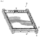
図1〜図5を参照すると、一実施例に係る電池セルアセンブリ10が提供されている。電池セルアセンブリ10は、長方形の環状フレーム部材20,22、電池セル30,32、及び冷却フィン40を含んでいる。
1 to 5, a
電池セルアセンブリ10の利点は、柔軟な熱伝導性シート84がある長方形のアルミニウムプレート80を含む冷却フィン40をアセンブリ10が使用しているという点である。
An advantage of the
その結果、ろう付け工程によるアルミニウムプレート上の相対的に粗い表面が、隣接する電池セルに対向して位置し、相対的に滑らかな表面を有する柔軟な熱伝導性シート84によりカバーされて、粗い表面による電池セルに対する研磨摩擦(abrasive rubbing)を除去する。
As a result, the relatively rough surface on the aluminum plate by the brazing process is covered with a flexible thermal
また、前記柔軟な熱伝導性シート84は、電池セルから発生した熱エネルギーをアルミニウムプレート80に伝導する優れた熱特性を有している。
Further, the flexible heat
長方形の環状フレーム部材20,22は、電池セル30,32及び冷却フィン40をそれらの間に固定させるために共に連結されるように構成されている。
The rectangular
一つの具体的な実施例において、長方形の環状フレーム部材20,22はプラスチックからなっている。しかし、代替実施例において、長方形の環状フレーム部材20,22は、当業者に公知の他の素材で構成されてもよい。
In one specific embodiment, the rectangular
それぞれの電池セル30,32は、作動電圧を発生させるものと構成されている。一つの具体的な実施例において、それぞれの電池セル30,32は、パウチ型リチウム−イオン電池セルである。もちろん、当業者に公知の他の類型の電池セルが使用されてもよい。また、一つの具体的な実施例において、電池セル30,32は電気的に互いに直列接続されている。
Each of the
電池セル30は、長方形のパウチ50と、パウチ50から延びている電極52,54とを含んでいる。電池セル30は、長方形の環状フレーム部材20と冷却フィン40との間に位置している。
The
電池セル32は、長方形のパウチ60、電極62、及び他の電極(図示せず)を含んでいる。電池セル32は、長方形の環状フレーム部材22と冷却フィン40との間に位置している。
The
図2〜図7を参照すると、冷却フィン40は、電池セル30,32の熱エネルギーを冷却フィン40を介して流動する冷媒又は液体に伝達することで、電池セル30,32を冷却するために提供される。冷却フィン40は、全般的に長方形のアルミニウムプレート80、チューブ82、及び柔軟な熱伝導性シート84を含んでいる。
Referring to FIGS. 2 to 7, the
長方形のアルミニウムプレート80は、第1サイド90及び第2サイド92を含んでいる。プレート80は、チューブ82の一部分を固定するための、それぞれアーチ状(arcuate-shaped)の第1、第2、第3、及び第4外郭エッジ部100,102,104,106(図5参照)をさらに含んでいる。すなわち、第1、第2、第3、及び第4外郭エッジ部100,102,104,106は、チューブ82を収容するように構成されているアーチ状のグルーブ109(図6参照)を設定している。
The
チューブ82は、全般的に長方形のアルミニウムプレート80の第1サイド90に連結されており、プレート80の第1、第2、第3、及び第4外郭エッジ部100,102,104,106に連結されており、プレート80の第1、第2、第3、及び第4外郭エッジ部100,102,104,106上に延びている。一つの具体的な実施例において、チューブ82はアルミニウムからなっている。しかし、チューブ82は、当業者に公知の他の材料で構成されてもよい。図4を参照すると、チューブ82は、流入口120、チューブ部(tube portions)122,124,126,128,130、及び排出口132を含んでいる。
The tube 82 is connected to the
流入口120はチューブ部122に連結されている。チューブ部122は、流入口120とチューブ部124との間に連結されている。チューブ部126は、チューブ部124とチューブ部128との間に連結されている。チューブ部130は、チューブ部128と排出口132との間に連結されている。
The
また、図4及び図5を参照すると、ろう付けを通じて、チューブ部122は第4外郭エッジ部(edge portion)106に連結され、チューブ部124は第1外郭エッジ部100に連結されている。ろう付けを通じて、チューブ部126は第2外郭エッジ部102に連結され、チューブ部128は第3外郭エッジ部104に連結されている。また、チューブ部130は、ろう付けを通じて第4外郭エッジ部106に連結されている。
4 and 5, the
図6及び図7を参照すると、柔軟な熱伝導性シート84は、全般的に長方形のアルミニウムプレート80の第1サイド90上に位置している。一つの具体的な例において、柔軟な熱伝導性シート84は、少なくとも部分的にグラファイト(graphite)で構成されており、0.25〜0.5ミリメートルの範囲の厚さを有する柔軟なシートを含む。
With reference to FIGS. 6 and 7, the flexible thermally
また、シート84は、200W/mK(Watts/meter-Kelvin)よりも大きい熱伝導性の内面(in-plane:例えば、プレート80に接触するシート84の表面と平面である)を有している。また、一つの具体的な実施例において、電池セル30と接触するシート84の一面は、0.8〜4.0マイクロインチの範囲の平均粗さを有している。もちろん、代替実施例において、シート84は、0.8よりも小さいか、または4.0よりも大きい平均粗さを有することができる。
The
また、一つの具体的な例において、シート84は、シート84の一方の面(one side)上に位置した減圧接着剤83(図10参照)をさらに含んでおり、このような減圧接着剤83は、シート84をプレート80の第1サイド90上に接着するために使用され、ここで、第1サイド90は、それに研磨ろう付け残留物(abrasive brazing residue)を有している。
Further, in one specific example, the
もちろん、代替例において、シート84は、当業者に公知の他の連結装置を用いてプレート80に連結してもよい。また、一つの具体的な例において、シート84は、全般的に長方形であり、電池セル30の全般的に長方形の表面の実質的に全体を覆うことができる大きさに形成されている。
Of course, in an alternative, the
もちろん、代替実施例において、シート84は、当業者に公知の他の形状及び大きさを有してもよい。シート84は、電池セル30の熱エネルギーを全般的に長方形のアルミニウムプレート80に伝達可能なように構成されている。また、プレート80は、熱エネルギーの少なくとも一部をチューブ82に伝達可能なように構成されている。特に、例えば、シート80は、グラテック・インターナショナル・ホールディング・インコーポレイテッド(GrafTech International Holdings Inc.)で製造されたSpreadershield SS-400からなることができる。
Of course, in alternative embodiments, the
図4を参照すると、作動の間、冷媒又は液体がソース(source)装置から流入口120に導入され、チューブ部122,124,126,128,130を介して排出口132に流動することになり、排出口132から受け取り(receiving)装置に排出される。電池セル30によって発生した熱エネルギーは、柔軟な熱伝導性シート84及び長方形のアルミニウムプレート80を介してチューブ82に伝導される。
Referring to FIG. 4, during operation, refrigerant or liquid is introduced from the source device into the
また、電池セル32によって発生した熱エネルギーは、長方形のアルミニウムプレート80を介してチューブ82に伝導される。また、チューブ82の熱エネルギーは、チューブ82を介して流動する冷媒又は流体に伝導される。
Further, the heat energy generated by the
したがって、チューブ82を介して流動する冷媒又は液体は、電池セル30,32の熱エネルギーを吸収して電池セル30,32の温度を下げる。
Therefore, the refrigerant or liquid flowing through the tube 82 absorbs the thermal energy of the
図1、図5、図8、及び図9を参照して、一実施例に係る押印機(stamping machine)170及びろう付け装置(brazing machine)172を使用して冷却フィン40を製造する方法のフローチャートを説明する。
With reference to FIGS. 1, 5, 8, and 9, a method of manufacturing a
過程150において、作業者は、全般的に長方形のアルミニウムプレート80、チューブ82、及び柔軟な熱伝導性シート84を提供する。全般的に長方形のアルミニウムプレート80は、第1サイド90及び第2サイド92を有している。
In step 150, the operator provides a generally
過程152において、押印機170は、全般的に長方形のアルミニウムプレート80の第1、第2、第3、及び第4外郭エッジ部100,102,104,106上にアーチ状のグルーブ109を形成する。
In
過程154において、作業者は、全般的に長方形のアルミニウムプレート80の第1、第2、第3、及び第4外郭エッジ部100,102,104,106上に第1チューブ82が位置できるように、チューブ82をアーチ状のグルーブ109に位置させる。
In step 154, the operator can place the first tube 82 on the first, second, third, and fourth
過程156において、ろう付け装置172は、チューブ82が全般的に長方形のアルミニウムプレート80の第1、第2、第3、及び第4外郭エッジ部100,102,104,106に付着できるように、チューブ82を全般的に長方形のアルミニウムプレート80の第1サイド90にろう付けする。
In step 156, the
過程158において、作業者は、柔軟な熱伝導性シート84を全般的に長方形のアルミニウムプレート80の第1サイド90に付着する。
In step 158, the operator attaches a flexible thermally
電池セルアセンブリ10と冷却フィン40の製造方法は、他の電池セルアセンブリ及び方法に対してかなりの利点を提供する。特に、電池セルアセンブリ10及び方法は、電池セルに対する粗い表面の研磨摩擦(abrasive rubbing)を防止するために、柔軟な熱伝導性シート84が隣接する電池セルに対面して位置するように、冷却フィン40の相対的に粗い表面上に柔軟な熱伝導性シート84が位置している冷却フィン40を使用する技術的効果を提供する。
The method of manufacturing
以上、本発明を単にいくつかの限定された数の実施例と関連付けて具体的に説明したが、本発明は、このような実施例に限定されないことを容易に理解できるであろう。むしろ、本発明は、言及していないが、本発明の範疇と内容に相応する、いかなる変形、変更、代替又は同等な配列を結合することによって修正が可能であるだろう。さらに、本発明の様々な実施例を説明したが、本発明の形態は前述したいくつかの実施例のみを含むものと解釈され得る。したがって、本発明は、上記の説明のみに限定されるものではない。 Although the present invention has been specifically described above in connection with only a limited number of embodiments, it will be readily understood that the present invention is not limited to such embodiments. Rather, the invention may be modified by combining any variations, alterations, alternatives or equivalent arrangements not mentioned but which are commensurate with the scope and content of the invention. Furthermore, although various embodiments of the present invention have been described, the forms of the present invention can be construed to include only some of the embodiments described above. Therefore, the present invention is not limited to the above description.
以上で説明したような本発明に係る電池セルアセンブリ及び製造方法は、柔軟な熱伝導性シートがある長方形のアルミニウムプレートを含む冷却フィンを使用することによって、ろう付け工程によるアルミニウムプレート上の相対的に粗い表面が、隣接する電池セルに対向して位置し、相対的に滑らかな表面を有する柔軟な熱伝導性シートによりカバーされることで、粗い表面による電池セルに対する研磨摩擦(abrasive rubbing)を除去すると共に、電池セルから発生した熱エネルギーを除去することができる効果がある。 The battery cell assembly and manufacturing method according to the present invention as described above can be obtained by using a cooling fin including a rectangular aluminum plate with a flexible thermal conductive sheet, so that The rough surface is opposed to the adjacent battery cell, and is covered with a flexible thermal conductive sheet having a relatively smooth surface, thereby reducing abrasive rubbing against the battery cell due to the rough surface. While removing, there is an effect that the heat energy generated from the battery cell can be removed.
10 電池セルアセンブリ
20,22 環状フレーム部材
30,32 電池セル
40 冷却フィン
80 アルミニウムプレート
84 熱伝導性シート
DESCRIPTION OF
Claims (12)
前記冷却フィンの柔軟な熱伝導性シートに対面して位置している電池セル(battery cell)と、
を含み、
前記全般的に長方形のアルミニウムプレートの前記第1サイドはその上に位置された研磨ろう付け残留物を有することを特徴とする、電池セルアセンブリ(battery cell assembly)。 A cooling fin comprising a generally rectangular-shaped aluminum plate, a tube, and a flexible thermally conductive sheet, said rectangular aluminum plate Includes a first side and a second side, the tube being connected to a first side of a rectangular aluminum plate, and at least first, second and third of the rectangular aluminum plate. Extending over peripheral edge portions, the flexible thermally conductive sheet comprising cooling fins located on a first side of a rectangular aluminum plate;
A battery cell positioned facing the flexible heat conductive sheet of the cooling fin;
Including
A battery cell assembly, wherein the first side of the generally rectangular aluminum plate has an abrasive brazing residue located thereon.
第1サイド及び第2サイドを有する全般的に長方形のアルミニウムプレート、チューブ及び柔軟な熱伝導性シートを提供する過程と、
前記チューブが長方形のアルミニウムプレートの少なくとも第1、第2、及び第3外郭エッジ部上に延びるように、前記チューブを長方形のアルミニウムプレートの第1サイドにろう付け(braze)する過程と、
前記柔軟な熱伝導性シートを長方形のアルミニウムプレートの前記第1サイド上に付着する過程と、
を含み、
前記全般的に長方形のアルミニウムプレートの前記第1サイドはその上に位置された研磨ろう付け残留物を有することを特徴とする、方法。 A method of manufacturing a cooling fin for a battery cell assembly, comprising:
Providing a generally rectangular aluminum plate having a first side and a second side, a tube and a flexible thermal conductive sheet;
Brazing the tube to the first side of the rectangular aluminum plate such that the tube extends over at least the first, second and third outer edges of the rectangular aluminum plate;
Depositing the flexible thermally conductive sheet on the first side of a rectangular aluminum plate;
Only including,
The method of claim 1, wherein the first side of the generally rectangular aluminum plate has an abrasive brazing residue located thereon .
前記アーチ状のグルーブにチューブを位置させる過程と、
をさらに含むことを特徴とする、請求項10に記載の方法。 Forming an arched groove on the first, second and third outer edges of the rectangular aluminum plate;
Positioning the tube in the arched groove;
The method according to claim 10, further comprising:
Applications Claiming Priority (2)
| Application Number | Priority Date | Filing Date | Title |
|---|---|---|---|
| US13/475,963 US8852781B2 (en) | 2012-05-19 | 2012-05-19 | Battery cell assembly and method for manufacturing a cooling fin for the battery cell assembly |
| PCT/KR2013/004015 WO2013176424A1 (en) | 2012-05-19 | 2013-05-08 | Battery cell assembly, and method for manufacturing cooling fin for battery cell assembly |
Publications (2)
| Publication Number | Publication Date |
|---|---|
| JP2015522911A JP2015522911A (en) | 2015-08-06 |
| JP6066532B2 true JP6066532B2 (en) | 2017-01-25 |
Family
ID=49581548
Family Applications (1)
| Application Number | Title | Priority Date | Filing Date |
|---|---|---|---|
| JP2015513885A Active JP6066532B2 (en) | 2012-05-19 | 2013-05-08 | Battery cell assembly and method for manufacturing cooling fin for battery cell assembly |
Country Status (6)
| Country | Link |
|---|---|
| US (2) | US8852781B2 (en) |
| EP (1) | EP2840626B1 (en) |
| JP (1) | JP6066532B2 (en) |
| KR (1) | KR101415050B1 (en) |
| CN (1) | CN104335384B (en) |
| WO (1) | WO2013176424A1 (en) |
Families Citing this family (41)
| Publication number | Priority date | Publication date | Assignee | Title |
|---|---|---|---|---|
| US9759495B2 (en) | 2008-06-30 | 2017-09-12 | Lg Chem, Ltd. | Battery cell assembly having heat exchanger with serpentine flow path |
| US20100275619A1 (en) * | 2009-04-30 | 2010-11-04 | Lg Chem, Ltd. | Cooling system for a battery system and a method for cooling the battery system |
| US9105950B2 (en) | 2012-03-29 | 2015-08-11 | Lg Chem, Ltd. | Battery system having an evaporative cooling member with a plate portion and a method for cooling the battery system |
| US9379420B2 (en) | 2012-03-29 | 2016-06-28 | Lg Chem, Ltd. | Battery system and method for cooling the battery system |
| US9605914B2 (en) | 2012-03-29 | 2017-03-28 | Lg Chem, Ltd. | Battery system and method of assembling the battery system |
| US8852781B2 (en) | 2012-05-19 | 2014-10-07 | Lg Chem, Ltd. | Battery cell assembly and method for manufacturing a cooling fin for the battery cell assembly |
| US9306199B2 (en) | 2012-08-16 | 2016-04-05 | Lg Chem, Ltd. | Battery module and method for assembling the battery module |
| US20140120390A1 (en) * | 2012-10-31 | 2014-05-01 | Lg Chem, Ltd. | Battery cell assembly and method for manufacturing a cooling fin for the battery cell assembly |
| US9083066B2 (en) | 2012-11-27 | 2015-07-14 | Lg Chem, Ltd. | Battery system and method for cooling a battery cell assembly |
| US8852783B2 (en) * | 2013-02-13 | 2014-10-07 | Lg Chem, Ltd. | Battery cell assembly and method for manufacturing the battery cell assembly |
| US9184424B2 (en) | 2013-07-08 | 2015-11-10 | Lg Chem, Ltd. | Battery assembly |
| US9444124B2 (en) | 2014-01-23 | 2016-09-13 | Lg Chem, Ltd. | Battery cell assembly and method for coupling a cooling fin to first and second cooling manifolds |
| KR102241333B1 (en) * | 2014-04-24 | 2021-04-16 | 에스케이이노베이션 주식회사 | Battery module for secondary battery |
| KR102210460B1 (en) * | 2014-04-24 | 2021-02-02 | 에스케이이노베이션 주식회사 | Battery cell assembly for secondary battery |
| US10084218B2 (en) | 2014-05-09 | 2018-09-25 | Lg Chem, Ltd. | Battery pack and method of assembling the battery pack |
| US10770762B2 (en) | 2014-05-09 | 2020-09-08 | Lg Chem, Ltd. | Battery module and method of assembling the battery module |
| KR101833526B1 (en) * | 2014-05-29 | 2018-02-28 | 주식회사 엘지화학 | Battery Module Having Water-Cooled Type Cooling Structure |
| KR102211192B1 (en) * | 2014-05-30 | 2021-02-02 | 에스케이이노베이션 주식회사 | Unit battery modue, Battery module and Battery pack And Method for manufacturing the same |
| US9484559B2 (en) | 2014-10-10 | 2016-11-01 | Lg Chem, Ltd. | Battery cell assembly |
| US9412980B2 (en) | 2014-10-17 | 2016-08-09 | Lg Chem, Ltd. | Battery cell assembly |
| US9786894B2 (en) | 2014-11-03 | 2017-10-10 | Lg Chem, Ltd. | Battery pack |
| US9627724B2 (en) | 2014-12-04 | 2017-04-18 | Lg Chem, Ltd. | Battery pack having a cooling plate assembly |
| KR101943489B1 (en) * | 2015-04-30 | 2019-01-29 | 주식회사 엘지화학 | Battery pack and method for manufacturing the same |
| US10249920B2 (en) | 2015-05-26 | 2019-04-02 | Lg Chem, Ltd. | Battery cell assembly |
| DE102015214662A1 (en) * | 2015-07-31 | 2017-02-02 | Volkswagen Aktiengesellschaft | Traction battery with battery cell modules |
| KR102065102B1 (en) * | 2015-09-02 | 2020-01-10 | 주식회사 엘지화학 | A battery module having an improved cooling structure |
| KR102018719B1 (en) | 2016-02-12 | 2019-09-04 | 주식회사 엘지화학 | Busbar for cooling battery cell and battery module using thereof |
| WO2017162292A1 (en) * | 2016-03-24 | 2017-09-28 | Volvo Truck Corporation | A vehicle cab body for a vehicle |
| USD855562S1 (en) | 2017-02-24 | 2019-08-06 | Ge Global Sourcing Llc | Battery module |
| KR102033064B1 (en) * | 2017-05-26 | 2019-10-16 | 엘티정밀(주) | A Manufacturing Method Of Battery Cooling Apparatus For Electric Behicle |
| FR3075336B1 (en) * | 2017-12-14 | 2020-02-07 | Valeo Systemes Thermiques | HEAT EXCHANGER FOR THERMAL MANAGEMENT OF AN ELECTRIC BATTERY |
| CN109560344B (en) * | 2018-02-07 | 2024-05-03 | 骆驼集团武汉光谷研发中心有限公司 | Pressure-resistant flexible liquid cooling fin |
| KR101881990B1 (en) | 2018-07-02 | 2018-07-25 | 주식회사 티엔디 | For lithium-ion batteries type Cooling Plate Manufacturing Method and System, thats goods |
| KR102204302B1 (en) * | 2018-09-13 | 2021-01-15 | 주식회사 엘지화학 | Battery module, battery pack comprising the battery module and vehicle comprising the battery pack |
| KR20220038848A (en) * | 2020-09-21 | 2022-03-29 | 주식회사 엘지에너지솔루션 | Battery Module With Improved Cooling Performance And Battery Pack Including It |
| IT202100005102A1 (en) * | 2021-03-04 | 2022-09-04 | Dynamic Tech S P A | COOLER |
| IT202100005117A1 (en) * | 2021-03-04 | 2022-09-04 | Dynamic Tech S P A | COOLER |
| US20220285753A1 (en) * | 2021-03-05 | 2022-09-08 | Bell Textron Inc. | Aircraft battery pack and associated cooling system |
| CN114571194B (en) * | 2022-04-11 | 2024-03-15 | 山东裕航特种合金装备有限公司 | Processing method and processing tool for whole hole site of battery tray of new energy automobile |
| GB2624034A (en) * | 2022-11-07 | 2024-05-08 | Jaguar Land Rover Ltd | Traction battery assembly with thermally conductive plate |
| FR3143864A1 (en) | 2022-12-19 | 2024-06-21 | Renault | Battery pack cell holding frame with cooling |
Family Cites Families (178)
| Publication number | Priority date | Publication date | Assignee | Title |
|---|---|---|---|---|
| DE436922C (en) | 1923-06-18 | 1926-11-11 | Fried Krupp Akt Ges Germaniawe | Cooling device for accumulator cells |
| US2391859A (en) | 1931-11-07 | 1946-01-01 | Hoover Co | Room cooling device |
| GB481891A (en) | 1936-09-18 | 1938-03-18 | India Rubber Gutta Percha Tele | Improvements in or relating to containers for electric storage cells |
| US2273244A (en) | 1940-04-03 | 1942-02-17 | Electric Storage Battery Co | Storage battery cell |
| SE319224B (en) | 1966-12-19 | 1970-01-12 | Asea Ab | |
| US3503558A (en) | 1968-03-14 | 1970-03-31 | Electrolux Corp | Exhaust diffusion manifold for a vacuum cleaner or the like |
| US3550681A (en) | 1968-12-30 | 1970-12-29 | Gen Motors Corp | Self-adjusting thermal connector |
| US4009752A (en) | 1975-02-24 | 1977-03-01 | Honeywell Information Systems Inc. | Warp-resistant heat sink |
| US3964930A (en) | 1975-07-21 | 1976-06-22 | United Technologies Corporation | Fuel cell cooling system |
| US4063590A (en) | 1976-10-22 | 1977-12-20 | Mcconnell Christopher L | Preheater for clothes dryer |
| US4305456A (en) | 1977-08-12 | 1981-12-15 | Paul Mueller Company | Condenser and hot water system |
| US4298904A (en) | 1979-12-17 | 1981-11-03 | The Boeing Company | Electronic conduction cooling clamp |
| US4322776A (en) | 1980-08-04 | 1982-03-30 | Hughes Aircraft Company | Thermal interconnection |
| US4444994A (en) | 1982-01-29 | 1984-04-24 | Varo, Inc. | Electrically insulated quick disconnect heat sink |
| US4518663A (en) | 1983-07-01 | 1985-05-21 | Energy Development Associates, Inc. | Electrolyte circulation subsystem |
| GB8329269D0 (en) | 1983-11-02 | 1983-12-07 | British Aerospace | Electronic apparatus stowage |
| US4777561A (en) | 1985-03-26 | 1988-10-11 | Hughes Aircraft Company | Electronic module with self-activated heat pipe |
| FR2580433B1 (en) | 1985-04-16 | 1987-08-14 | Socapex | THERMAL CONNECTOR FOR PRINTED CIRCUIT BOARD COATED WITH ELECTRONIC COMPONENTS |
| US4849858A (en) | 1986-10-20 | 1989-07-18 | Westinghouse Electric Corp. | Composite heat transfer means |
| US4995240A (en) | 1987-01-27 | 1991-02-26 | Eaton Corporation | Controlling refrigeration having control module directly attached on valve body |
| US5057968A (en) | 1989-10-16 | 1991-10-15 | Lockheed Corporation | Cooling system for electronic modules |
| US4982785A (en) | 1990-03-06 | 1991-01-08 | Inter-City Products Corporation (Usa) | Serpentine heat exchanger |
| US5186250A (en) | 1990-05-11 | 1993-02-16 | Showa Aluminum Kabushiki Kaisha | Tube for heat exchangers and a method for manufacturing the tube |
| CH679620A5 (en) | 1990-12-11 | 1992-03-13 | Sulzer Ag | |
| US5071652A (en) | 1990-12-11 | 1991-12-10 | Globe-Union Inc. | Metal oxide hydrogen battery having improved heat transfer properties |
| US5214564A (en) | 1992-04-23 | 1993-05-25 | Sunstrand Corporation | Capacitor assembly with integral cooling apparatus |
| FR2697677B1 (en) | 1992-11-02 | 1994-12-30 | Europ Accumulateurs | Thermoregulated storage battery, especially for electric vehicles. |
| JP2903913B2 (en) | 1992-11-10 | 1999-06-14 | 松下電器産業株式会社 | Storage battery system |
| US5356735A (en) | 1993-05-10 | 1994-10-18 | General Motors Corporation | Heated/cooled battery |
| US5329988A (en) | 1993-05-28 | 1994-07-19 | The Allen Group, Inc. | Heat exchanger |
| US5520976A (en) | 1993-06-30 | 1996-05-28 | Simmonds Precision Products Inc. | Composite enclosure for electronic hardware |
| US5472802A (en) | 1993-10-25 | 1995-12-05 | Ovonic Battery Company, Inc. | Sealed hydride batteries, including a new lid-terminal seal and electrode tab collecting comb |
| US5663007A (en) | 1994-02-23 | 1997-09-02 | Matsushita Electric Industrial Co., Ltd. | Sealed storage battery and method for manufacturing the same |
| JP3260951B2 (en) | 1994-02-23 | 2002-02-25 | 松下電器産業株式会社 | Single cell and unit cell of sealed alkaline storage battery |
| US5346786A (en) | 1994-03-21 | 1994-09-13 | Hodgetts Philip J | Modular rack mounted battery system |
| JPH08111244A (en) | 1994-10-12 | 1996-04-30 | Nissan Motor Co Ltd | Layer-built battery device |
| JP3451142B2 (en) | 1994-11-18 | 2003-09-29 | 本田技研工業株式会社 | Battery assembly with temperature control mechanism |
| US5731568A (en) * | 1995-10-13 | 1998-03-24 | Arctic Fox, Inc. | Battery heating device and method |
| JP3745424B2 (en) | 1995-11-06 | 2006-02-15 | 東芝電池株式会社 | Battery manufacturing method |
| JPH09219213A (en) | 1996-02-09 | 1997-08-19 | Nissan Motor Co Ltd | Secondary battery for electric vehicle and temperature rise alleviation device therefor |
| JP3225192B2 (en) | 1996-04-10 | 2001-11-05 | 本田技研工業株式会社 | Battery exhaust gas control system |
| DE19639115C2 (en) | 1996-09-24 | 2003-08-07 | Behr Gmbh & Co | Plate-shaped heat transfer element |
| JP3240973B2 (en) | 1997-03-05 | 2001-12-25 | トヨタ自動車株式会社 | Battery cooling system for vehicles |
| EP1030389B1 (en) | 1997-03-24 | 2003-01-08 | Matsushita Electric Industrial Co., Ltd. | Battery housing with integrated cables for voltage measuring |
| US6087036A (en) | 1997-07-25 | 2000-07-11 | 3M Innovative Properties Company | Thermal management system and method for a solid-state energy storing device |
| US6117584A (en) * | 1997-07-25 | 2000-09-12 | 3M Innovative Properties Company | Thermal conductor for high-energy electrochemical cells |
| JP3830243B2 (en) | 1997-10-06 | 2006-10-04 | トヨタ自動車株式会社 | Battery power supply |
| JP3790946B2 (en) | 1997-12-08 | 2006-06-28 | 株式会社ヴァレオサーマルシステムズ | Heat exchanger |
| FR2774215B1 (en) | 1998-01-29 | 2000-02-25 | Alsthom Cge Alcatel | WATERPROOF MONOBLOCK BATTERY PROVIDED WITH A COOLING DEVICE |
| US6255015B1 (en) | 1998-08-23 | 2001-07-03 | Ovonic Battery Company, Inc. | Monoblock battery assembly |
| JP4231127B2 (en) | 1998-09-03 | 2009-02-25 | パナソニック株式会社 | Integrated battery temperature control method and apparatus |
| US6176095B1 (en) | 1999-01-19 | 2001-01-23 | Carrier Corporation | Pretrip device for testing of a refrigeration system compressor |
| JP4778602B2 (en) | 1999-07-22 | 2011-09-21 | パナソニック株式会社 | Secondary battery |
| JP4416266B2 (en) | 1999-10-08 | 2010-02-17 | パナソニック株式会社 | Sealed prismatic battery |
| JP4252172B2 (en) | 1999-10-12 | 2009-04-08 | 株式会社日本自動車部品総合研究所 | Battery cooling system |
| US6399238B1 (en) | 1999-12-13 | 2002-06-04 | Alcatel | Module configuration |
| JP3777981B2 (en) | 2000-04-13 | 2006-05-24 | トヨタ自動車株式会社 | Vehicle power supply |
| WO2001080333A1 (en) * | 2000-04-13 | 2001-10-25 | Fmc Corporation | Battery pack or battery providing increased heat dissipation |
| DE10021161A1 (en) | 2000-04-29 | 2001-10-31 | Vb Autobatterie Gmbh | Method for determining the state of charge and the load capacity of an electric accumulator |
| US6533031B1 (en) * | 2000-05-09 | 2003-03-18 | Marconi Communications, Inc. | Method for thermal management of a battery in an outdoor equipment cabinet |
| JP4116238B2 (en) | 2000-05-19 | 2008-07-09 | 株式会社タイカ | Thermally conductive sheet having electromagnetic shielding properties |
| US6462949B1 (en) | 2000-08-07 | 2002-10-08 | Thermotek, Inc. | Electronic enclosure cooling system |
| JP3727840B2 (en) | 2000-09-29 | 2005-12-21 | 株式会社東芝 | Battery pack and portable electronic device |
| JP3576092B2 (en) | 2000-11-10 | 2004-10-13 | 松下冷機株式会社 | refrigerator |
| US6569556B2 (en) | 2001-01-29 | 2003-05-27 | General Motors Corporation | Cooling system for a battery pack |
| JP4892788B2 (en) | 2001-04-23 | 2012-03-07 | トヨタ自動車株式会社 | Battery module |
| US6422027B1 (en) | 2001-05-03 | 2002-07-23 | Ford Global Tech., Inc. | System and method for cooling a battery pack |
| JP4361229B2 (en) | 2001-07-04 | 2009-11-11 | 日産自動車株式会社 | Battery system |
| US6512347B1 (en) | 2001-10-18 | 2003-01-28 | General Motors Corporation | Battery having an integral cooling system |
| JP3969254B2 (en) | 2001-10-29 | 2007-09-05 | 株式会社デンソー | Battery temperature management device |
| JP2003188323A (en) | 2001-12-19 | 2003-07-04 | Sony Corp | Graphite sheet and its manufacturing method |
| US7650935B2 (en) | 2001-12-21 | 2010-01-26 | Behr Gmbh & Co. Kg | Heat exchanger, particularly for a motor vehicle |
| KR20040082437A (en) | 2002-02-19 | 2004-09-24 | 쓰리엠 이노베이티브 프로퍼티즈 컴파니 | Temperature control apparatus and method for high energy electrochemical cells |
| US6821671B2 (en) | 2002-03-01 | 2004-11-23 | Lg Chem, Ltd. | Method and apparatus for cooling and positioning prismatic battery cells |
| JP2003282112A (en) | 2002-03-26 | 2003-10-03 | Denso Corp | Intermediate heat exchanger for fuel cell |
| JP3733079B2 (en) | 2002-03-29 | 2006-01-11 | 三洋電機株式会社 | Cold storage |
| JP4242665B2 (en) | 2002-05-13 | 2009-03-25 | パナソニック株式会社 | Battery pack cooling device and secondary battery |
| KR100471233B1 (en) | 2002-06-26 | 2005-03-10 | 현대자동차주식회사 | Method of generating maximum charge current and maximum discharge current for battery in a hybrid electric vehicle |
| CA2392610C (en) | 2002-07-05 | 2010-11-02 | Long Manufacturing Ltd. | Baffled surface cooled heat exchanger |
| US7010644B2 (en) | 2002-08-29 | 2006-03-07 | Micron Technology, Inc. | Software refreshed memory device and method |
| US7143124B2 (en) | 2002-12-06 | 2006-11-28 | Sun Microsystems, Inc. | Detection of dead regions during incremental collection |
| US7070874B2 (en) | 2002-12-24 | 2006-07-04 | Fuelcell Energy, Inc. | Fuel cell end unit with integrated heat exchanger |
| JP2004333115A (en) | 2003-04-16 | 2004-11-25 | Showa Denko Kk | Heat exchanger, and method for manufacturing the same |
| JP2004361022A (en) * | 2003-06-05 | 2004-12-24 | Denso Corp | Heat exchanger |
| US20050026014A1 (en) | 2003-07-31 | 2005-02-03 | Michael Fogaing | Polymer batteries having thermal exchange apparatus |
| JP4045340B2 (en) | 2003-08-13 | 2008-02-13 | 現代自動車株式会社 | Battery effective power calculation method and calculation system |
| JP4578867B2 (en) | 2003-09-30 | 2010-11-10 | 株式会社日立製作所 | Hydrogen storage / supply device and system thereof, distributed power source using the same, and automobile |
| US7270910B2 (en) | 2003-10-03 | 2007-09-18 | Black & Decker Inc. | Thermal management systems for battery packs |
| US6826948B1 (en) | 2003-10-09 | 2004-12-07 | Delphi Technologies, Inc. | Leak detection apparatus for a liquid circulation cooling system |
| JP3963165B2 (en) * | 2003-10-10 | 2007-08-22 | 日産自動車株式会社 | Assembled battery |
| JP4078553B2 (en) | 2003-10-21 | 2008-04-23 | 新神戸電機株式会社 | Lithium battery module for vehicles |
| JP2005147443A (en) | 2003-11-12 | 2005-06-09 | Calsonic Kansei Corp | Laminated type heat exchanger |
| US20050134038A1 (en) | 2003-12-17 | 2005-06-23 | Eaton Corporation | Fitting for fluid conveyance |
| US7237395B2 (en) | 2003-12-22 | 2007-07-03 | General Electric Company | Methods and apparatus for controlling refrigerators |
| KR100799866B1 (en) | 2004-03-16 | 2008-01-31 | 주식회사 엘지화학 | Secondary battery having a high safety |
| JP4570888B2 (en) | 2004-03-18 | 2010-10-27 | 富士重工業株式会社 | Power storage device |
| JP2005349955A (en) | 2004-06-10 | 2005-12-22 | Toyota Motor Corp | Cooling structure for power storage mechanism |
| CA2583168C (en) | 2004-10-05 | 2013-01-29 | Nitto Denko Corporation | Fuel cell and power generating method |
| JP2006139928A (en) | 2004-11-10 | 2006-06-01 | Nissan Motor Co Ltd | Battery system |
| KR100637472B1 (en) | 2004-12-07 | 2006-10-23 | 삼성에스디아이 주식회사 | Secondary battery module |
| KR100876458B1 (en) | 2004-12-24 | 2008-12-29 | 주식회사 엘지화학 | Battery cartridge of novel structure and open battery module containing it |
| JP2006236826A (en) | 2005-02-25 | 2006-09-07 | Toyota Motor Corp | Battery pack |
| EP1875582B1 (en) | 2005-03-16 | 2017-02-22 | Ford Global Technologies, LLC | Power supply system comprising temperature sensor stations |
| KR100965049B1 (en) | 2005-03-23 | 2010-06-21 | 에스케이에너지 주식회사 | Layer-up for high power lithium polymer battery |
| KR20060102853A (en) | 2005-03-25 | 2006-09-28 | 삼성에스디아이 주식회사 | Secondary battery module |
| US9653748B2 (en) | 2005-04-14 | 2017-05-16 | Enerdel, Inc. | Apparatus and method for securing battery cell packs |
| US7278389B2 (en) | 2005-04-19 | 2007-10-09 | Murat Kirakosyan | Automobile intake air flow plenum and plenum diverter |
| KR100880386B1 (en) | 2005-06-03 | 2009-01-23 | 주식회사 엘지화학 | Secondary Battery of Novel Structure and Battery Pack Having the Same |
| JP4415910B2 (en) | 2005-07-12 | 2010-02-17 | トヨタ自動車株式会社 | Hybrid vehicle structure |
| KR100765659B1 (en) | 2005-08-09 | 2007-10-10 | 현대자동차주식회사 | Fuel cell-stack structure for automobile |
| JP2007048750A (en) | 2005-08-10 | 2007-02-22 | Samsung Sdi Co Ltd | Battery module |
| JP4600212B2 (en) | 2005-08-23 | 2010-12-15 | 株式会社デンソー | Supercritical refrigeration cycle equipment |
| US7658224B2 (en) | 2005-09-19 | 2010-02-09 | Dana Canada Corporation | Flanged connection for heat exchanger |
| US20070087266A1 (en) | 2005-10-18 | 2007-04-19 | Debbi Bourke | Modular battery system |
| US8030886B2 (en) | 2005-12-21 | 2011-10-04 | Nuventix, Inc. | Thermal management of batteries using synthetic jets |
| DE102006015568B3 (en) | 2006-04-04 | 2007-05-31 | Daimlerchrysler Ag | Production of a heat exchanger module for heat exchangers for electrochemical storage comprises preparing deep-drawn material strips, deep drawing heat exchanger channels and a profile in the material strips and further processing |
| JP4857896B2 (en) | 2006-05-11 | 2012-01-18 | トヨタ自動車株式会社 | Battery pack and vehicle |
| DE102007028252B4 (en) | 2006-06-26 | 2017-02-02 | Denso Corporation | Refrigerant cycle device with ejector |
| JP2008054379A (en) | 2006-08-22 | 2008-03-06 | Calsonic Kansei Corp | Battery cooling system for vehicle |
| JP4251204B2 (en) | 2006-08-31 | 2009-04-08 | 日産自動車株式会社 | Battery module |
| JP2008062875A (en) | 2006-09-11 | 2008-03-21 | Calsonic Kansei Corp | Battery cooling system for vehicle |
| KR100921346B1 (en) | 2006-09-25 | 2009-10-13 | 주식회사 엘지화학 | Mid-Large Battery Module and Battery Module Assembly |
| JP2008080995A (en) | 2006-09-28 | 2008-04-10 | Denso Corp | Cooling system |
| US7531270B2 (en) * | 2006-10-13 | 2009-05-12 | Enerdel, Inc. | Battery pack with integral cooling and bussing devices |
| KR100889241B1 (en) | 2006-10-23 | 2009-03-17 | 주식회사 엘지화학 | Member of Connecting Electrode in Battery Module |
| US7797958B2 (en) | 2006-11-15 | 2010-09-21 | Glacier Bay, Inc. | HVAC system controlled by a battery management system |
| KR101064240B1 (en) | 2006-11-27 | 2011-09-14 | 주식회사 엘지화학 | Power Supply System Having Heat Radiation-Preventing Structure |
| JP2008159440A (en) | 2006-12-25 | 2008-07-10 | Calsonic Kansei Corp | Vehicular battery cooling system |
| US8268505B2 (en) | 2007-01-25 | 2012-09-18 | Honda Motor Co., Ltd. | Fuel cell system |
| DE102007004567A1 (en) | 2007-01-30 | 2008-07-31 | Robert Bosch Gmbh | Electrochemical cell e.g. coffee-bag cell, housing device for traction system of e.g. hybrid motor vehicle, has cell and lugs for contacting, where cell is enclosed between housing parts, which clamp cell between parts using pressing force |
| WO2008111162A1 (en) | 2007-03-13 | 2008-09-18 | Hoshizaki Denki Kabushiki Kaisha | Cooling storage chamber and method for operating the same |
| KR100942985B1 (en) | 2007-03-21 | 2010-02-17 | 주식회사 엘지화학 | Middle or Large-sized Battery Pack Case Providing Improved Distribution Uniformity in Coolant Flux |
| KR101212362B1 (en) | 2007-04-04 | 2012-12-13 | 에스케이이노베이션 주식회사 | Temperature controller for electric vehicle using thermoelectric semiconductor |
| JP5236210B2 (en) | 2007-05-10 | 2013-07-17 | カルソニックカンセイ株式会社 | Battery module structure of the battery |
| US7846573B2 (en) | 2007-06-01 | 2010-12-07 | Cobasys, Llc | Coolant manifold |
| JP4438830B2 (en) | 2007-06-19 | 2010-03-24 | コニカミノルタビジネステクノロジーズ株式会社 | Resin composition, molded body, electrophotographic transfer belt, and image forming apparatus |
| JP5137480B2 (en) | 2007-06-29 | 2013-02-06 | 三洋電機株式会社 | Power supply for vehicle |
| JP2009054297A (en) | 2007-08-23 | 2009-03-12 | Toshiba Corp | Battery pack |
| KR100872225B1 (en) | 2007-11-05 | 2008-12-05 | 엘지전자 주식회사 | Control method of refrigerator |
| US8409743B2 (en) | 2007-11-28 | 2013-04-02 | Sanyo Electric Co., Ltd. | Battery system with battery cells arranged in array alignment |
| KR20100095457A (en) | 2007-12-05 | 2010-08-30 | 에네르델, 인코포레이티드 | Battery assembly with temperature control device |
| US8628872B2 (en) | 2008-01-18 | 2014-01-14 | Lg Chem, Ltd. | Battery cell assembly and method for assembling the battery cell assembly |
| DE102008011466A1 (en) | 2008-02-27 | 2009-09-03 | Robert Bosch Gmbh | battery module |
| EP2262048A4 (en) | 2008-03-24 | 2012-08-08 | Sanyo Electric Co | Battery device and battery unit |
| KR20090107443A (en) | 2008-04-08 | 2009-10-13 | 쏘씨에떼 드 베이뀔르 엘렉트리끄 | Electrical battery comprising flexible generating elements and a system for the mechanical and thermal conditioning of said elements |
| US7851080B2 (en) | 2008-04-09 | 2010-12-14 | Gm Global Technology Operations, Inc. | Battery cooling plate design with discrete channels |
| US8465863B2 (en) | 2008-04-09 | 2013-06-18 | GM Global Technology Operations LLC | Batteries and components thereof and methods of making and assembling the same |
| US8215432B2 (en) | 2008-05-09 | 2012-07-10 | GM Global Technology Operations LLC | Battery thermal system for vehicle |
| JP5159425B2 (en) * | 2008-05-19 | 2013-03-06 | 古河電池株式会社 | Battery module |
| US8426050B2 (en) | 2008-06-30 | 2013-04-23 | Lg Chem, Ltd. | Battery module having cooling manifold and method for cooling battery module |
| US7883793B2 (en) | 2008-06-30 | 2011-02-08 | Lg Chem, Ltd. | Battery module having battery cell assemblies with alignment-coupling features |
| US8486552B2 (en) | 2008-06-30 | 2013-07-16 | Lg Chem, Ltd. | Battery module having cooling manifold with ported screws and method for cooling the battery module |
| US9140501B2 (en) | 2008-06-30 | 2015-09-22 | Lg Chem, Ltd. | Battery module having a rubber cooling manifold |
| US9759495B2 (en) | 2008-06-30 | 2017-09-12 | Lg Chem, Ltd. | Battery cell assembly having heat exchanger with serpentine flow path |
| US8067111B2 (en) | 2008-06-30 | 2011-11-29 | Lg Chem, Ltd. | Battery module having battery cell assembly with heat exchanger |
| US8663829B2 (en) | 2009-04-30 | 2014-03-04 | Lg Chem, Ltd. | Battery systems, battery modules, and method for cooling a battery module |
| US8852778B2 (en) | 2009-04-30 | 2014-10-07 | Lg Chem, Ltd. | Battery systems, battery modules, and method for cooling a battery module |
| US20100275619A1 (en) | 2009-04-30 | 2010-11-04 | Lg Chem, Ltd. | Cooling system for a battery system and a method for cooling the battery system |
| US8403030B2 (en) | 2009-04-30 | 2013-03-26 | Lg Chem, Ltd. | Cooling manifold |
| US8703318B2 (en) | 2009-07-29 | 2014-04-22 | Lg Chem, Ltd. | Battery module and method for cooling the battery module |
| US8399118B2 (en) | 2009-07-29 | 2013-03-19 | Lg Chem, Ltd. | Battery module and method for cooling the battery module |
| US8399119B2 (en) | 2009-08-28 | 2013-03-19 | Lg Chem, Ltd. | Battery module and method for cooling the battery module |
| US20110053052A1 (en) * | 2009-08-28 | 2011-03-03 | Enerfuel, Inc. | Fuel cell composite flow field element and method of forming the same |
| RU2592786C2 (en) * | 2009-11-09 | 2016-07-27 | Энердел, Инк. | Scalable battery module |
| US9780421B2 (en) * | 2010-02-02 | 2017-10-03 | Dana Canada Corporation | Conformal heat exchanger for battery cell stack |
| KR101205180B1 (en) * | 2010-05-18 | 2012-11-27 | 주식회사 엘지화학 | Cooling Member of Compact Structure and Excellent Stability and Battery Module Employed with the Same |
| KR101205181B1 (en) * | 2010-05-18 | 2012-11-27 | 주식회사 엘지화학 | Cooling Member of Novel Structure and Battery Module Employed with the Same |
| US8574740B2 (en) * | 2010-08-10 | 2013-11-05 | GM Global Technology Operations LLC | Molded frame with corrugated cooling fin for air-cooled battery |
| US8673473B2 (en) * | 2010-08-10 | 2014-03-18 | GM Global Technology Operations LLC | Integrated cooling fin and frame |
| CN103069644B (en) * | 2010-08-16 | 2016-01-27 | 株式会社Lg化学 | There is the battery module of compact structure and good heat radiating characteristic and adopt the medium-and-large-sized battery pack of this battery module |
| US8662153B2 (en) | 2010-10-04 | 2014-03-04 | Lg Chem, Ltd. | Battery cell assembly, heat exchanger, and method for manufacturing the heat exchanger |
| JP2012204129A (en) * | 2011-03-25 | 2012-10-22 | Hitachi Maxell Ltd | Battery pack |
| KR101305403B1 (en) * | 2011-12-30 | 2013-09-05 | 대한칼소닉주식회사 | Method of welding heat insulating board for secondary battery and secondary battery cell of zig assembly for heat insulating board |
| US9105950B2 (en) | 2012-03-29 | 2015-08-11 | Lg Chem, Ltd. | Battery system having an evaporative cooling member with a plate portion and a method for cooling the battery system |
| US8852781B2 (en) | 2012-05-19 | 2014-10-07 | Lg Chem, Ltd. | Battery cell assembly and method for manufacturing a cooling fin for the battery cell assembly |
| US9306199B2 (en) | 2012-08-16 | 2016-04-05 | Lg Chem, Ltd. | Battery module and method for assembling the battery module |
| US9960395B2 (en) | 2012-08-16 | 2018-05-01 | Lg Chem, Ltd. | Battery module |
| US9083066B2 (en) | 2012-11-27 | 2015-07-14 | Lg Chem, Ltd. | Battery system and method for cooling a battery cell assembly |
-
2012
- 2012-05-19 US US13/475,963 patent/US8852781B2/en active Active
-
2013
- 2013-02-21 KR KR1020130018542A patent/KR101415050B1/en active IP Right Grant
- 2013-05-08 EP EP13793145.7A patent/EP2840626B1/en active Active
- 2013-05-08 WO PCT/KR2013/004015 patent/WO2013176424A1/en active Application Filing
- 2013-05-08 CN CN201380026173.4A patent/CN104335384B/en active Active
- 2013-05-08 JP JP2015513885A patent/JP6066532B2/en active Active
-
2014
- 2014-09-17 US US14/488,349 patent/US9461343B2/en active Active
Also Published As
| Publication number | Publication date |
|---|---|
| KR101415050B1 (en) | 2014-07-21 |
| US8852781B2 (en) | 2014-10-07 |
| EP2840626B1 (en) | 2017-02-22 |
| EP2840626A4 (en) | 2015-05-20 |
| EP2840626A1 (en) | 2015-02-25 |
| JP2015522911A (en) | 2015-08-06 |
| CN104335384A (en) | 2015-02-04 |
| CN104335384B (en) | 2017-03-22 |
| US20130309542A1 (en) | 2013-11-21 |
| KR20130129076A (en) | 2013-11-27 |
| US20150000134A1 (en) | 2015-01-01 |
| WO2013176424A1 (en) | 2013-11-28 |
| US9461343B2 (en) | 2016-10-04 |
Similar Documents
| Publication | Publication Date | Title |
|---|---|---|
| JP6066532B2 (en) | Battery cell assembly and method for manufacturing cooling fin for battery cell assembly | |
| KR101590000B1 (en) | Battery Cell Assembly and Method for Manufacturing A Cooling Fin for the Battery Cell Assembly | |
| KR101658583B1 (en) | Battery cell assembly and method for manufacturing cooling fin for battery cell assembly | |
| JP5557405B2 (en) | Battery module and battery module cooling method | |
| KR101750066B1 (en) | Water-cooled type secondary battery | |
| US20180248238A1 (en) | Graphene enhanced cooling fin | |
| US9711828B2 (en) | Heat shrink joining of battery cell components | |
| JP2016040770A (en) | Heat exchange plate for temperature management of battery pack | |
| JP6994303B2 (en) | Heat transfer device for assembled batteries | |
| US20190373768A1 (en) | Electronics cold plate | |
| KR20130013947A (en) | Battery pack having all-in-one cooling tube and heat sink | |
| US9368770B2 (en) | Battery cooling module foot profile design for a jointless conductive FIN/foot compressed interface connection | |
| JP2019185902A (en) | Cooling and heating device for battery pack | |
| CN106034394B (en) | Radiator and heat abstractor | |
| JP2011069552A (en) | Heat exchanger | |
| CN210225130U (en) | Energy-saving motor structure | |
| TWI468098B (en) | Improvement of heat radiating plate and its manufacturing method | |
| CN210576335U (en) | Battery module | |
| JP2017117611A (en) | Battery pack | |
| JP6204048B2 (en) | Cooler | |
| CN103808194A (en) | Heat exchanger |
Legal Events
| Date | Code | Title | Description |
|---|---|---|---|
| A977 | Report on retrieval |
Free format text: JAPANESE INTERMEDIATE CODE: A971007 Effective date: 20151221 |
|
| A131 | Notification of reasons for refusal |
Free format text: JAPANESE INTERMEDIATE CODE: A131 Effective date: 20160118 |
|
| A521 | Request for written amendment filed |
Free format text: JAPANESE INTERMEDIATE CODE: A523 Effective date: 20160418 |
|
| A131 | Notification of reasons for refusal |
Free format text: JAPANESE INTERMEDIATE CODE: A131 Effective date: 20160725 |
|
| A521 | Request for written amendment filed |
Free format text: JAPANESE INTERMEDIATE CODE: A523 Effective date: 20161025 |
|
| TRDD | Decision of grant or rejection written | ||
| A01 | Written decision to grant a patent or to grant a registration (utility model) |
Free format text: JAPANESE INTERMEDIATE CODE: A01 Effective date: 20161121 |
|
| A61 | First payment of annual fees (during grant procedure) |
Free format text: JAPANESE INTERMEDIATE CODE: A61 Effective date: 20161219 |
|
| R150 | Certificate of patent or registration of utility model |
Ref document number: 6066532 Country of ref document: JP Free format text: JAPANESE INTERMEDIATE CODE: R150 |
|
| R250 | Receipt of annual fees |
Free format text: JAPANESE INTERMEDIATE CODE: R250 |
|
| R250 | Receipt of annual fees |
Free format text: JAPANESE INTERMEDIATE CODE: R250 |
|
| R250 | Receipt of annual fees |
Free format text: JAPANESE INTERMEDIATE CODE: R250 |
|
| S111 | Request for change of ownership or part of ownership |
Free format text: JAPANESE INTERMEDIATE CODE: R313111 |
|
| R350 | Written notification of registration of transfer |
Free format text: JAPANESE INTERMEDIATE CODE: R350 |
|
| R250 | Receipt of annual fees |
Free format text: JAPANESE INTERMEDIATE CODE: R250 |
|
| R250 | Receipt of annual fees |
Free format text: JAPANESE INTERMEDIATE CODE: R250 |