US6117584A - Thermal conductor for high-energy electrochemical cells - Google Patents
Thermal conductor for high-energy electrochemical cells Download PDFInfo
- Publication number
- US6117584A US6117584A US08/900,428 US90042897A US6117584A US 6117584 A US6117584 A US 6117584A US 90042897 A US90042897 A US 90042897A US 6117584 A US6117584 A US 6117584A
- Authority
- US
- United States
- Prior art keywords
- conductor
- wall structure
- electrochemical cell
- shaped
- thermally conductive
- Prior art date
- Legal status (The legal status is an assumption and is not a legal conclusion. Google has not performed a legal analysis and makes no representation as to the accuracy of the status listed.)
- Expired - Lifetime
Links
Images


Classifications
-
- H—ELECTRICITY
- H01—ELECTRIC ELEMENTS
- H01M—PROCESSES OR MEANS, e.g. BATTERIES, FOR THE DIRECT CONVERSION OF CHEMICAL ENERGY INTO ELECTRICAL ENERGY
- H01M10/00—Secondary cells; Manufacture thereof
- H01M10/04—Construction or manufacture in general
- H01M10/0436—Small-sized flat cells or batteries for portable equipment
-
- H—ELECTRICITY
- H01—ELECTRIC ELEMENTS
- H01M—PROCESSES OR MEANS, e.g. BATTERIES, FOR THE DIRECT CONVERSION OF CHEMICAL ENERGY INTO ELECTRICAL ENERGY
- H01M10/00—Secondary cells; Manufacture thereof
- H01M10/60—Heating or cooling; Temperature control
- H01M10/61—Types of temperature control
- H01M10/613—Cooling or keeping cold
-
- H—ELECTRICITY
- H01—ELECTRIC ELEMENTS
- H01M—PROCESSES OR MEANS, e.g. BATTERIES, FOR THE DIRECT CONVERSION OF CHEMICAL ENERGY INTO ELECTRICAL ENERGY
- H01M10/00—Secondary cells; Manufacture thereof
- H01M10/60—Heating or cooling; Temperature control
- H01M10/64—Heating or cooling; Temperature control characterised by the shape of the cells
- H01M10/647—Prismatic or flat cells, e.g. pouch cells
-
- H—ELECTRICITY
- H01—ELECTRIC ELEMENTS
- H01M—PROCESSES OR MEANS, e.g. BATTERIES, FOR THE DIRECT CONVERSION OF CHEMICAL ENERGY INTO ELECTRICAL ENERGY
- H01M10/00—Secondary cells; Manufacture thereof
- H01M10/60—Heating or cooling; Temperature control
- H01M10/65—Means for temperature control structurally associated with the cells
- H01M10/653—Means for temperature control structurally associated with the cells characterised by electrically insulating or thermally conductive materials
-
- H—ELECTRICITY
- H01—ELECTRIC ELEMENTS
- H01M—PROCESSES OR MEANS, e.g. BATTERIES, FOR THE DIRECT CONVERSION OF CHEMICAL ENERGY INTO ELECTRICAL ENERGY
- H01M10/00—Secondary cells; Manufacture thereof
- H01M10/60—Heating or cooling; Temperature control
- H01M10/65—Means for temperature control structurally associated with the cells
- H01M10/655—Solid structures for heat exchange or heat conduction
- H01M10/6553—Terminals or leads
-
- H—ELECTRICITY
- H01—ELECTRIC ELEMENTS
- H01M—PROCESSES OR MEANS, e.g. BATTERIES, FOR THE DIRECT CONVERSION OF CHEMICAL ENERGY INTO ELECTRICAL ENERGY
- H01M10/00—Secondary cells; Manufacture thereof
- H01M10/60—Heating or cooling; Temperature control
- H01M10/65—Means for temperature control structurally associated with the cells
- H01M10/655—Solid structures for heat exchange or heat conduction
- H01M10/6554—Rods or plates
-
- H—ELECTRICITY
- H01—ELECTRIC ELEMENTS
- H01M—PROCESSES OR MEANS, e.g. BATTERIES, FOR THE DIRECT CONVERSION OF CHEMICAL ENERGY INTO ELECTRICAL ENERGY
- H01M10/00—Secondary cells; Manufacture thereof
- H01M10/60—Heating or cooling; Temperature control
- H01M10/65—Means for temperature control structurally associated with the cells
- H01M10/655—Solid structures for heat exchange or heat conduction
- H01M10/6556—Solid parts with flow channel passages or pipes for heat exchange
-
- H—ELECTRICITY
- H01—ELECTRIC ELEMENTS
- H01M—PROCESSES OR MEANS, e.g. BATTERIES, FOR THE DIRECT CONVERSION OF CHEMICAL ENERGY INTO ELECTRICAL ENERGY
- H01M6/00—Primary cells; Manufacture thereof
- H01M6/04—Cells with aqueous electrolyte
- H01M6/06—Dry cells, i.e. cells wherein the electrolyte is rendered non-fluid
- H01M6/10—Dry cells, i.e. cells wherein the electrolyte is rendered non-fluid with wound or folded electrodes
- H01M2006/106—Elliptic wound cells
-
- H—ELECTRICITY
- H01—ELECTRIC ELEMENTS
- H01M—PROCESSES OR MEANS, e.g. BATTERIES, FOR THE DIRECT CONVERSION OF CHEMICAL ENERGY INTO ELECTRICAL ENERGY
- H01M50/00—Constructional details or processes of manufacture of the non-active parts of electrochemical cells other than fuel cells, e.g. hybrid cells
- H01M50/20—Mountings; Secondary casings or frames; Racks, modules or packs; Suspension devices; Shock absorbers; Transport or carrying devices; Holders
- H01M50/218—Mountings; Secondary casings or frames; Racks, modules or packs; Suspension devices; Shock absorbers; Transport or carrying devices; Holders characterised by the material
- H01M50/22—Mountings; Secondary casings or frames; Racks, modules or packs; Suspension devices; Shock absorbers; Transport or carrying devices; Holders characterised by the material of the casings or racks
- H01M50/222—Inorganic material
- H01M50/224—Metals
-
- H—ELECTRICITY
- H01—ELECTRIC ELEMENTS
- H01M—PROCESSES OR MEANS, e.g. BATTERIES, FOR THE DIRECT CONVERSION OF CHEMICAL ENERGY INTO ELECTRICAL ENERGY
- H01M50/00—Constructional details or processes of manufacture of the non-active parts of electrochemical cells other than fuel cells, e.g. hybrid cells
- H01M50/50—Current conducting connections for cells or batteries
- H01M50/531—Electrode connections inside a battery casing
- H01M50/534—Electrode connections inside a battery casing characterised by the material of the leads or tabs
-
- H—ELECTRICITY
- H01—ELECTRIC ELEMENTS
- H01M—PROCESSES OR MEANS, e.g. BATTERIES, FOR THE DIRECT CONVERSION OF CHEMICAL ENERGY INTO ELECTRICAL ENERGY
- H01M50/00—Constructional details or processes of manufacture of the non-active parts of electrochemical cells other than fuel cells, e.g. hybrid cells
- H01M50/50—Current conducting connections for cells or batteries
- H01M50/531—Electrode connections inside a battery casing
- H01M50/536—Electrode connections inside a battery casing characterised by the method of fixing the leads to the electrodes, e.g. by welding
-
- H—ELECTRICITY
- H01—ELECTRIC ELEMENTS
- H01M—PROCESSES OR MEANS, e.g. BATTERIES, FOR THE DIRECT CONVERSION OF CHEMICAL ENERGY INTO ELECTRICAL ENERGY
- H01M50/00—Constructional details or processes of manufacture of the non-active parts of electrochemical cells other than fuel cells, e.g. hybrid cells
- H01M50/50—Current conducting connections for cells or batteries
- H01M50/531—Electrode connections inside a battery casing
- H01M50/538—Connection of several leads or tabs of wound or folded electrode stacks
-
- H—ELECTRICITY
- H01—ELECTRIC ELEMENTS
- H01M—PROCESSES OR MEANS, e.g. BATTERIES, FOR THE DIRECT CONVERSION OF CHEMICAL ENERGY INTO ELECTRICAL ENERGY
- H01M6/00—Primary cells; Manufacture thereof
- H01M6/04—Cells with aqueous electrolyte
- H01M6/06—Dry cells, i.e. cells wherein the electrolyte is rendered non-fluid
- H01M6/10—Dry cells, i.e. cells wherein the electrolyte is rendered non-fluid with wound or folded electrodes
-
- H—ELECTRICITY
- H01—ELECTRIC ELEMENTS
- H01M—PROCESSES OR MEANS, e.g. BATTERIES, FOR THE DIRECT CONVERSION OF CHEMICAL ENERGY INTO ELECTRICAL ENERGY
- H01M6/00—Primary cells; Manufacture thereof
- H01M6/14—Cells with non-aqueous electrolyte
- H01M6/18—Cells with non-aqueous electrolyte with solid electrolyte
- H01M6/181—Cells with non-aqueous electrolyte with solid electrolyte with polymeric electrolytes
-
- Y—GENERAL TAGGING OF NEW TECHNOLOGICAL DEVELOPMENTS; GENERAL TAGGING OF CROSS-SECTIONAL TECHNOLOGIES SPANNING OVER SEVERAL SECTIONS OF THE IPC; TECHNICAL SUBJECTS COVERED BY FORMER USPC CROSS-REFERENCE ART COLLECTIONS [XRACs] AND DIGESTS
- Y02—TECHNOLOGIES OR APPLICATIONS FOR MITIGATION OR ADAPTATION AGAINST CLIMATE CHANGE
- Y02E—REDUCTION OF GREENHOUSE GAS [GHG] EMISSIONS, RELATED TO ENERGY GENERATION, TRANSMISSION OR DISTRIBUTION
- Y02E60/00—Enabling technologies; Technologies with a potential or indirect contribution to GHG emissions mitigation
- Y02E60/10—Energy storage using batteries
-
- Y—GENERAL TAGGING OF NEW TECHNOLOGICAL DEVELOPMENTS; GENERAL TAGGING OF CROSS-SECTIONAL TECHNOLOGIES SPANNING OVER SEVERAL SECTIONS OF THE IPC; TECHNICAL SUBJECTS COVERED BY FORMER USPC CROSS-REFERENCE ART COLLECTIONS [XRACs] AND DIGESTS
- Y02—TECHNOLOGIES OR APPLICATIONS FOR MITIGATION OR ADAPTATION AGAINST CLIMATE CHANGE
- Y02P—CLIMATE CHANGE MITIGATION TECHNOLOGIES IN THE PRODUCTION OR PROCESSING OF GOODS
- Y02P70/00—Climate change mitigation technologies in the production process for final industrial or consumer products
- Y02P70/50—Manufacturing or production processes characterised by the final manufactured product
Definitions
- This invention relates generally to energy storage devices, and more particularly, to a thermal conductor for use with high-energy electrochemical cells.
- Such advanced energy storage systems typically produce a significant amount of heat which, if not properly dissipated, can result in a thermal runaway condition and eventual destruction of the energy storage device, as well as the system being powered by the energy storage device.
- a conventional approach of providing a heat transfer mechanism external to a high-energy electrochemical cell or grouping of cells, for example, may be inadequate to effectively dissipate heat from internal portions of the cells.
- the severity of consequences resulting from short-circuit and thermal run-away conditions increases significantly as system voltage and current demands increase.
- the present invention is directed to a thermal conductor for use with an electrochemical energy storage device.
- the thermal conductor is attached to one or both of the anode and cathode contacts of an electrochemical cell.
- a resilient portion of the conductor varies in height or position to maintain contact between the conductor and an adjacent wall structure of a containment vessel in response to relative movement between the conductor and the wall structure.
- the thermal conductor conducts current into and out of the electrochemical cell and conducts thermal energy between the electrochemical cell and thermally conductive and electrically resistive material disposed between the conductor and the wall structure.
- the thermal conductor may be fabricated to include a resilient portion having one of a substantially C-shaped, double C-shaped, Z-shaped, V-shaped, O-shaped, S-shaped, or finger-shaped cross-section.
- An elastomeric spring element may be configured so as to be captured by the resilient conductor for purposes of enhancing the functionality of the thermal conductor.
- the spring element may include a protrusion that provides electrical insulation between the spring conductor and a spring conductor of an adjacently disposed electrochemical cell in the presence of relative movement between the cells and the wall structure.
- the thermal conductor may also be fabricated from a sheet of electrically conductive material and affixed to the contacts of a number of electrochemical cells.
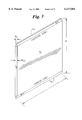
- FIG. 1 illustrates an embodiment of a solid-state, thin-film electrochemical cell having a prismatic configuration
- FIGS. 2A-2C illustrate various embodiments of a thin-film electrochemical cell
- FIG. 3 is an illustration of another embodiment of an electrochemical cell having a prismatic configuration
- FIG. 4 provides a more detailed illustration of the anode and cathode contact regions of the electrochemical cell shown in FIG. 3;
- FIG. 5 is an illustration of an electrochemical cell including an electrical conductor attached to an end portion of the anode and cathode contacts of the cell, respectively;
- FIG. 6 is an illustration of an energy storage module including a stack of interconnected electrochemical cells
- FIGS. 7 and 8 illustrate a relationship between the maximum temperature in a cell stack and the number of adjacent short-circuited cells with and without employment of an external thermal management scheme
- FIG. 9 is a top view of an electrochemical cell including anode and cathode conductor contacts constrained between substantially planar wall structures of a containment vessel;
- FIGS. 10A-10B illustrate an embodiment of a prismatic electrochemical cell including a pair of thermal conductors respectively attached to the anode and cathode contacts of the cell;
- FIG. 11 is a cross-sectional view of an electrochemical cell having a thermal conductor disposed adjacent a wall structure of an enclosure, the wall structure having a surface treatment or separate film material disposed thereon which exhibits good thermal conductance and poor electrical conductivity characteristics;
- FIG. 12 is a top view illustration of a grouping of electrochemical cells aligned such that the cell contacts are situated adjacent a wall of a containment vessel, a number of gaps being developed between some of the cell contacts and the wall due to variations in cell length and wall warpage;
- FIG. 13 is a top view illustration of an embodiment of a thermal conductor which varies in height or position to maintain mechanical engagement with the wall of a containment vessel;
- FIGS. 14A-14D illustrate the spring-like characteristics of a thermal conductor
- FIG. 15 is an illustration of a spring insulator captured within a thermal conductor that enhances the spring-like properties of the thermal conductor
- FIG. 16 illustrates various configurations of a thermal conductor, including a spring insulator, in compressed and uncompressed states
- FIGS. 17-22 illustrate additional embodiments of a thermal conductor
- FIG. 1 there is illustrated an embodiment of a solid-state, thin-film electrochemical cell which may be utilized in the fabrication of a rechargeable electrochemical cell for use in a wide range of applications.
- the electrochemical cell 20 is shown as having a flat wound prismatic configuration in which a thin-film solid electrolyte 26 is disposed between a film 24 constituting an anode and a film 28 constituting a cathode.
- a central cathode current collector film 30 is disposed between each of the cathode films 28 to form a bi-face cell configuration.
- a mono-face cell configuration may alternatively be employed in which a single cathode current collector 30 is associated with a single anode/electrolyte/cathode element combination.
- an insulating film is typically disposed between individual anode/electrolyte/cathode/collector element combinations.
- the anode films 24 are laterally offset relative to the cathode current collector 30 so as to expose the anode 24 along a first edge 25 of the cell 20, and to expose the cathode current collector 30 along a second edge 23 of the cell 20.
- the embodiment shown in FIG. 1 includes a core element 22, such as a foam or metal spring element, about which the thin-film electrochemical cell 20 is wound.
- FIGS. 2A-2C there is illustrated various embodiments of a thin-film electrochemical cell which may be used in the fabrication of a rechargeable electrochemical energy storage device.
- a thin-film electrochemical cell may be packaged in a "jelly roll" configuration so as to form a generally cylindrical cell structure in which a first edge 42 of the cell forms a positive contact 43, and a second edge 44 forms a negative contact 45.
- the positive and negative contacts 43, 45 are formed typically by use of a known metal spraying technique.
- FIGS. 2B and 2C illustrate alternative packaging configurations for a thin-film rechargeable electrochemical cell.
- a flat roll configuration, shown in FIG. 2B, or a flat stack configuration, shown in FIG. 2C, provides for the aggregation of a relatively large thin-film cell surface area within a relatively small packaging configuration.
- Such geometries minimize I 2 R losses and allow for the efficient transfer of heat to and from the multi-layered cell structure.
- various electrochemical cell configurations other than those depicted in the figures may be appropriate to meet the electrical, mechanical, and thermal requirements of a particular application.
- the electrochemical cell 20 includes a solid polymer electrolyte 26 which constitutes an ion transporting membrane, a lithium metal anode 24, and a vanadium oxide cathode 28. These film elements are fabricated to form a thin-film laminated prismatic structure, which may include an insulation film such as polypropylene film.
- a known sputtering metallization process is employed to form current collecting contacts along the edges 25, 23 of the anode and cathode current collecting films 24, 30, respectively. It is noted that the metal-sprayed contacts provide for superior current collection along the length of the anode and cathode film edges 25, 23, and demonstrate good electrical contact and heat transfer characteristics.
- the active materials constituting the solid-state, thin-film electrochemical cell retain chemical and mechanical integrity at temperatures well beyond typical operating temperatures. For example, operating temperatures on the order of 180° C. may be tolerated.
- the electrochemical cells depicted generally in the figures may be fabricated in accordance with the methodologies disclosed in U.S. Pat. Nos. 5,423,110, 5,415,954, and 4,897,917.
- FIGS. 3-4 there is shown an embodiment of a prismatic electrochemical cell 70 which includes an anode contact 72 and a cathode contact 74 formed respectively along opposing edges of the electrochemical cell 70.
- the electrochemical cell 70 shown in FIG. 4 illustrates the laterally offset anode and cathode current collecting film layers 73, 75 which terminate respectively at common anode and cathode contacts 72, 74. It is noted that a copper spraying technique is typically employed to form anode and cathode contacts 72, 74.
- the active portion 76 of the cell 70 produces an appreciable amount of thermal energy which is preferentially conducted along the anode and cathode film surfaces, thus sharing the same conductivity path as that for the electrical energy produced by the cell 70.
- the contacts 72, 74 respectively disposed on the edge portions of the extended anode and cathode film layers 73, 75 provide a site for establishing both electrical and thermal connectivity with the cell 70.
- the electrochemical cell shown in FIGS. 3-4 may be fabricated to have a length L of approximately 135 mm, a height H of approximately 149 mm, and a width W ec of approximately 5.4 mm or W ec of approximately 5.86 mm when including a foam core element 22.
- the width W c of the cathode contact 74 and the anode contact 72 is approximately 3.9 mm, respectively.
- a cell having these dimensions typically exhibits a nominal energy rating of approximately 36.5 Wh, a peak power rating of 87.0 W at 80 percent depth of discharge (DOD), a cell capacity of 14.4 Ah, and a nominal voltage rating of 3.1 volts at full charge.
- a number of electrochemical cells 82 may be selectively interconnected in a parallel and/or series relationship to achieve a desired voltage and current rating.
- a number of the electrochemical cells 82 may be grouped together and connected in parallel to common positive and negative power conductors or terminals to form a cell pack 83.
- a number of the electrochemical cell packs 83 may then be connected in series to form a module 80.
- a number of modules 80 may be connected in series to constitute larger and more powerful energy producing battery configurations.
- each individual cell 82 provides for a total energy output of approximately 36.5 Wh.
- Each cell pack 83 provides for a total energy output of approximately 292 Wh, while each module 80 provides for a total energy output of 1.75 kWh.
- a battery (not shown), constituted by 24 series connected modules 80, provides for a total energy output of approximately 42 kWh.
- FIGS. 7-8 illustrate the effect of short-circuit conditions on cell temperature for a stack of cells in physical contact with one another.
- the graph shown in FIG. 7 illustrates a relationship between the maximum temperature in a cell stack as a function of the number of adjacent short-circuited cells when no external thermal management scheme is employed.
- Five plots of data corresponding to five state of charge (SOC) levels are depicted.
- FIG. 8 provides a similar plot of data with the exception that an external thermal management system is employed to enhance the transfer of heat out of the cells constituting the cell stack.
- the solid line provided at 180° C. represents the melting temperature of lithium, and that 130° C. is considered an upper security or safety limit. It is understood that the 130° C. limit is provided to demonstrate that a particular energy storing device may be designed to operate below a maximum temperature which may be different from a cell breakdown temperature.
- FIGS. 7-8 demonstrates the significant impact of short-circuit conditions on cell stack temperature.
- the data plotted in FIG. 7 suggests that no greater than one short-circuited cell can be tolerated within a cell stack without jeopardizing the integrity of the stack, assuming that no external cooling apparatus is employed.
- Those skilled in the art will immediately appreciate the importance of providing for the efficient transfer of thermal energy out of a thin-film electrochemical cell in order to minimize the adverse effects of over-temperature conditions within a stack of closely situated cells.
- the embodiment of an energy storage module 80 shown in FIG. 6 includes a stack 84 of electrochemical cells 82 which may be enclosed in a containment vessel 86 that typically includes a thermal management system.
- the containment vessel 86 is shown as including a serpentine fluid channel 88 within which a heat transfer fluid passes. Thermal energy may be transferred into or out of the cells 82 forming the stack 84 through use of an external thermal management system (e.g., cooling channels) in combination with a thermal conductor provided on either one or both of the anode and cathode contacts of individual cells.
- an external thermal management system e.g., cooling channels
- an external thermal management system of the type shown in FIG. 6 may be employed in combination with a resilient thermal and electrical conductor constructed in accordance with the principles of the present invention to effectively regulate the internal temperature of a thin-film electrochemical energy storage device.
- an additional factor that further complicates the effort to provide an effective thermal and electrical conduction apparatus for high-energy electrochemical cells concerns cyclical changes in cell volume that occur in various types of thin-film electrochemical cells.
- the volume of an electrochemical cell of the type described previously with regard to FIG. 1 varies during charge and discharge cycling due to the migration of lithium ions into and out of the lattice structure of the cathode material. This migration creates a corresponding increase and decrease in total cell volume on the order of approximately five to six percent or more during charging and discharging, respectively.
- a cell 90 is shown as being constrained between substantially planar walls 92 of a containment structure.
- the cell 90 includes two opposing surfaces 91, 93 each having a large surface area relative to the surface area of the four edges of the cell 90.
- An external force, F E is applied to the opposing surfaces 91, 93 so as to maintain the cell 90 in a state of compression.
- the magnitude of the external force, F E typically ranges between approximately 5 psi to 100 psi during charge/discharge cycling.
- the external force, F E may be maintained at a constant magnitude, such as 20 psi for example, or may vary between a minimum and a maximum value, such as between approximately 5 and 100 psi. Further, the external force, F E , may be produced by contact between one surface 91 of the cell 90 and an active force generation mechanism, while the opposing surface 93 is restricted from movement by a stationary structure. Alternatively, an active force generating mechanism may be applied to both opposing surfaces 91, 93 of the electrochemical cell 90.
- an electrochemical cell 100 includes a thermal conductor 102 which is spot welded or otherwise attached to each of the anode and cathode contacts 104, 106, respectively.
- a thermal conductor 102 is typically disposed along the length of the anode contact 104 and the cathode contact 106, and typically includes an electrical connection lead 108 for conducting current into and out of the electrochemical cell 100, the current being collected and conducted along the anode and cathode contacts 104, 106.
- the thermal conductor 102 provides a thermal flux path for efficiently transferring thermal energy between the cell 100 and a thermally conductive, electrically resistive material or structure disposed adjacent the cell 100.
- a thermally conductive, electrically resistive material or structure as described herein refers to a surface coating/treatment or separate material that permits a sufficient amount of heat to be conducted therethrough, yet is electrically resistive to the flow of current relative to a current path provided for conducting current into and out of an electrochemical cell.
- An anodized coating for example, may have a thickness that permits a sufficient amount of thermal energy to be conducted therethrough, yet is sufficiently resistive to electrical current relative to the anode and cathode contacts or the thermal conductor.
- a thermally conductive polymer element may be employed, with the density of thermally conductive particles impregnated therein being selected to provide a desired balance between thermal and electrical conductivity characteristics.
- the thermal conductor 102 is configured so as to exhibit a spring-like character which provides for substantially continuous contact between the cell 100 and a stationary structure, such as a metallic wall surface, disposed adjacent the cell 100 in the presence of relative movement between the cell 100 and the wall structure. It is noted that the thermal conductor 102 or other thermal conductor that effects the transfer of heat between the cell 100 and a thermally conductive structure or material adjacent the cell 100 may be utilized along only one or both of the anode and cathode contacts 104, 106.
- the thermal conductor 102 includes a copper tab 103 that extends along the length of a sprayed metal anode or cathode contact 111.
- the copper tab 103 includes a resilient member 109 through which heat is transferred between the cell 100 and an adjacently disposed heat sink, such as a wall of a metallic housing.
- the copper tab 103 is spot welded to the sprayed metal contact 111 at a number of weld locations 101.
- a flexible electrical lead 107 is ultrasonically welded at a location 105 toward the end of the copper tab 103. Current is conducted primarily along the sprayed metal contact 111 of the cell 100 and communicated to external connections via the flexible electrical leads 107.
- a thermal conductor that provides the above-described thermal, electrical, and mechanical advantages should be fabricated from a material which has a relatively high thermal and electrical conductivity.
- the material should have good surface characteristics for establishing contacts with both a separate planar support surface and an integral metallization layer formed on the anode or cathode contacts of the electrochemical cell.
- the material used to fabricate the thermal conductor contacts should have a relatively low force of compression so as to avoid damaging the edges of the cell or the surface of the wall structures adjacent the cell. Also, the thermal conductor contacts should be configured to minimize the length of the thermal flux path, yet maximize the cross-sectional area in order to optimize the heat transfer characteristics of the thermal conductor contacts.
- a suitable material for use in the fabrication of a thermal conductor having the above-described characteristics is pure copper, although other metals and alloys may be employed.
- FIG. 11 there is shown a side cross-sectional view of an electrochemical cell 120 including a thermal conductor 122 situated adjacent a wall 128 of a containment vessel having a coating of thermally conductive, electrically resistive material 124.
- the thermal conductor 122 conducts current into and out of the electrochemical cell 120, and includes a lead portion 126 which provides for convenient connectivity to an external energy consuming element and to a charging unit.
- the thermal conductor 122 further provides a thermal flux path through which thermal energy is efficiently transferred between the cell 120 and the wall 128 of the containment vessel coated with a thermally conductive material 124.
- the thermally conductive material 124 may constitute an anodized aluminum coating developed on the surface of an aluminum casing or other structure 128.
- a conformal plastic coating may be applied over the anodized surface.
- a thin sheet of plastic or mineral-based material may be disposed adjacent the wall 128 of the containment vessel.
- the thermally conductive coating 124 which may alternatively constitute a compliant thermal compound or material, provides for the transferring of thermal energy between the cell 120 and the thermally conductive material 124, yet is sufficiently electrically resistive to ensure that current is conducted preferentially along the anode and cathode contacts of the cell 120 and the lead 126 of the thermal conductor 122.
- FIGS. 12-13 there is depicted an aggregation of electrochemical cells 140 which typically vary in dimension depending on allowable manufacturing and assembly tolerances. Because of such variations and vessel wall warpage, or other imperfections inherent or induced in the wall 142 of a containment vessel, a number of gaps 144 will typically develop between the vessel wall 142 and a number of the electrochemical cells 140.
- thermal conductance is severely reduced upon the occurrence of a gap 144 forming between a cell contact 146 and the vessel wall 142.
- a compliant thermal compound may improve thermal conductance in the presence of small gaps 144, such compounds are generally ineffective for maintaining thermal conductance across large gaps 144.
- the thermal conductor contacts 148 are formed to provide a relatively high degree of dimensional take-up in order to accommodate assembly tolerances when installing the electrochemical cells 140 between substantially stationary support structures 142 of a containment vessel.
- the thermal conductor contacts 148 also exhibit a relatively high degree of spring-back to accommodate possible wall deflections and variations in the separation distance between the cells 140 and a wall structure 142 over time.
- a thermal conductor 154 is formed to include a substantially C-shaped portion which exhibits good dimensional take-up and spring-back properties.
- the thermal conductor 154 is shown in a relaxed state prior to attachment to a contact 152 of an electrochemical cell 150.
- the relaxed state of the thermal conductor 154 aids in the process of attaching the thermal conductor 154 to the cell.
- a wiping procedure is typically performed on the thermal conductor 154 to ensure that the thermal conductor 154 will collapse properly when installed in a compressed state between the walls of a constraining structure.
- FIG. 14B A pre-installation configuration of the thermal conductor 154 is shown in FIG. 14B.
- the thermal conductor 154 is shown in a compressed state which would typically arise when the cell 150 is installed between the walls of a constraining structure.
- the take-up range, R T represents the total distance in which the thermal conductor 154 may be compressed without significantly reducing its spring-back properties.
- FIG. 14D illustrates the spring-back property of the thermal conductor 154 that would be implicated in response to relative movement between the cell 150 and the walls of a constraining structure abutting the thermal conductor 154.
- the magnitude of the spring-back displacement in this illustrative example is depicted as the dimension R S .
- the thermal conductor 154 shown in FIGS. 14A-14D provides for spring-back in the range of approximately 1-3 mm, which is sufficiently large to compensate for relative movement of approximately 1-3 mm between the electrochemical cell and an adjacent wall structure. It is noted that a thermal conductor having a substantially C-shaped cross-section and a nominal height value of approximately 3 mm varies in thermal conductance as a function of height variation, due to changes in the area of contact between the thermal conductor and the adjacent wall.
- a height variation of ⁇ 0.5 mm results in a corresponding conductance change ranging between approximately 450-575 W/m 2 C.
- the conductance of a non-compressed thermal conductor having a nominal height of 3 mm, without introduction of a thermally conductive compound, is approximately 200 W/m 2 C. Introducing a compliant thermal compound may improve the conductance characteristics of the thermal conductor during compression and extension of the conductor.
- FIGS. 15-16 there is illustrated an alternative embodiment of a thermal conductor having a substantially C-shaped cross-section and including an elastomeric spring element retained within the thermal conductor.
- the elastomeric spring element generally improves the spring-back characteristics of the thermal conductor, and may be fabricated using stock materials, such as cylindrical elastomeric tubing 177 or thermally conductive foam. Alternatively, a more complex spring element may be fashioned from elastomeric material.
- the thermal conductor 174 includes a hooked-tip 171 which retains the elastomeric spring element 176/177 within the thermal conductor structure.
- the elastomeric spring 176 may include an insulating protrusion 178 and an insulating stub 180 which provides electrical isolation for the thermal conductor 174 and contact 172 with respect to the conductors and contacts of adjacent cells 170. Additionally, a stop 182 may be included to prevent over-collapsing or possible crushing of the thermal conductor 174.
- FIG. 16 illustrates the dynamic insulating capability of the elastomeric spring 176 when transitioning between uncompressed and compressed states.
- the thermal conductor 174 has a height, H 1 , of approximately 4 mm at an initial compressed state. Under moderate compression, the thermal conductor 174 has a height, H 2 , of approximately 3 mm. When the thermal conductor 174 is at a fully compressed state such that the stop 182 contacts the inner surface of the upper portion of the spring 176, the conductor 174 has a height of approximately 2 mm.
- the spring elements 176/177 each have a diameter, D 1 , of approximately 3.8 mm.
- thermal conductor which exhibits the mechanical, thermal, and electrical characteristics described herein may be formed to include spring-like portions having configurations that differ from those illustrated herein.
- FIGS. 17-19 three other embodiments of a thermal conductor well-suited for use with prismatic electrochemical cells are shown in FIGS. 17-19. These embodiments provide for the efficient transfer of electrical current and thermal energy into and out of a prismatic electrochemical cell.
- the thermal conductor shown in FIG. 17 is formed to include a substantially double C-shaped portion which permits the thermal conductor to collapse and expand in a spring-like manner.
- Z-shaped, V-shaped, and S-shaped thermal conductor contacts are respectively shown in FIGS. 18-20 which, as with the other illustrative embodiments described above, expand and collapse to accommodate dimensional variations and positional shifting between the cell and the walls of a structure constraining the cell.
- a stacked S-shaped thermal conductor configuration is shown in FIG. 21 which advantageously increases the number of thermal conduction paths between the cell and an adjacent heat sink.
- FIG. 22 illustrates another embodiment of a thermal conductor which includes two finger-shaped or bent L-shaped resilient conductors 204 affixed to the sprayed metal contact 202 of the cell 200.
- An elastomeric element 206 is situated between the collapsible finger-shaped conductors 204 to prevent over-collapsing of the conductors 204.
- FIG. 23 illustrates another embodiment of a thermal conductor which may be applied to a number of electrochemical cells 212.
- the thermal conductor 210 is configured as a flat sheet of metallic or other electrically conductive material.
- the thermal conductor 210 spans across the anode and/or cathode current collecting contacts 214 of a number of cells 212. It can be seen that the thermal conductor 210 connects a number of the cells 212 in parallel, such as eight cells 212 that form a cell pack for example. Current is conducted along the thermal conductor 210 and transferred into and out of the parallel connected cells via an electrical contact or lead (not shown) attached to the thermal conductor 210.
- Heat is transferred through the thermal conductor 210 and to a heat sink, such as the wall of a metallic enclosure, disposed adjacent the thermal conductor 210.
- a heat sink such as the wall of a metallic enclosure, disposed adjacent the thermal conductor 210.
- a thin sheet of plastic or mica, for example, may be situated between the thermal conductor 210 and the heat sink.
- the heat sink may be treated to include an anodized surface or other electrically resistive, thermally conductive material.
- the thermal conductor comprises a number of laterally offset anode and cathode film layers 73, 75 and the anode and cathode contacts 72, 74.
- one or both of the anode and cathode contacts 72, 74 may directly engage the thermally conductive, electrically resistive material disposed on the wall of a containment vessel.
- the resilient portion of the thermal conductor constitutes the laterally offset anode and cathode film layer 73, 75 which flex in response to relative movement between the cell and the vessel wall.
Abstract
Description
              TABLE 1
______________________________________
        Thermal Conductivity
  (W/m° C.)
          Direction
   of the Direction  Specific
   film of the Density Heat
  Section thickness connectors (kg/m.sup.3) (J/kg° C.)
______________________________________
  Active Section 0.4042 48.10 1356 1411
  Anode Side, 0.0466 28.90 252 2714
  Inactive Zone
  Cathode Side, 0.0388 18.45 441 1470
  Inactive Side
  Complete Cell   1218 1435
______________________________________
Other Components
                                Density x
   Thermal Conductivity specific heat
  Component (W/m° C.) (kJ/m.sup.3 ° C.)
______________________________________
  Cell's core (foam) 0.071 401.3
  Metallization 366.7 3254.6
  Spring-type 134.5 3254.6
  conductor
  Vessel wall - 178.8 2566.9
  anodized
______________________________________
Claims (32)
Priority Applications (7)
| Application Number | Priority Date | Filing Date | Title |
|---|---|---|---|
| US08/900,428 US6117584A (en) | 1997-07-25 | 1997-07-25 | Thermal conductor for high-energy electrochemical cells |
| DE1998624005 DE69824005T2 (en) | 1997-07-25 | 1998-07-23 | Thermal conductor for electrochemical high energy cells |
| PCT/US1998/015301 WO1999005749A1 (en) | 1997-07-25 | 1998-07-23 | Thermal conductor for high-energy electrochemical cells |
| JP2000504630A JP4593773B2 (en) | 1997-07-25 | 1998-07-23 | Thermal conductor of high energy electrochemical cell |
| CA 2297845 CA2297845C (en) | 1997-07-25 | 1998-07-23 | Thermal conductor for high-energy electrochemical cells |
| EP19980937045 EP0998766B1 (en) | 1997-07-25 | 1998-07-23 | Thermal conductor for high-energy electrochemical cells |
| AU85843/98A AU8584398A (en) | 1997-07-25 | 1998-07-23 | Thermal conductor for high-energy electrochemical cells |
Applications Claiming Priority (1)
| Application Number | Priority Date | Filing Date | Title |
|---|---|---|---|
| US08/900,428 US6117584A (en) | 1997-07-25 | 1997-07-25 | Thermal conductor for high-energy electrochemical cells |
Publications (1)
| Publication Number | Publication Date |
|---|---|
| US6117584A true US6117584A (en) | 2000-09-12 |
Family
ID=25412508
Family Applications (1)
| Application Number | Title | Priority Date | Filing Date |
|---|---|---|---|
| US08/900,428 Expired - Lifetime US6117584A (en) | 1997-07-25 | 1997-07-25 | Thermal conductor for high-energy electrochemical cells |
Country Status (7)
| Country | Link |
|---|---|
| US (1) | US6117584A (en) |
| EP (1) | EP0998766B1 (en) |
| JP (1) | JP4593773B2 (en) |
| AU (1) | AU8584398A (en) |
| CA (1) | CA2297845C (en) |
| DE (1) | DE69824005T2 (en) |
| WO (1) | WO1999005749A1 (en) |
Cited By (41)
| Publication number | Priority date | Publication date | Assignee | Title |
|---|---|---|---|---|
| US6258485B1 (en) * | 1998-07-14 | 2001-07-10 | Ngk Insulators, Ltd | Lithium secondary battery |
| US20030165734A1 (en) * | 2002-03-01 | 2003-09-04 | Hinton Michael L. | Method and apparatus for cooling and positioning prismatic battery cells |
| US20050026014A1 (en) * | 2003-07-31 | 2005-02-03 | Michael Fogaing | Polymer batteries having thermal exchange apparatus |
| US20060208700A1 (en) * | 2005-03-21 | 2006-09-21 | Kim Tae-Yong | Rechargeable battery and its fabrication |
| US20060251960A1 (en) * | 2005-04-20 | 2006-11-09 | Junill Yoon | Housing member for battery module |
| US20070126396A1 (en) * | 2005-12-02 | 2007-06-07 | Lg Chem, Ltd. | Battery module of high cooling efficiency |
| US20080193830A1 (en) * | 2006-10-13 | 2008-08-14 | Enerdel, Inc. | Battery assembly with temperature control device |
| US7531270B2 (en) | 2006-10-13 | 2009-05-12 | Enerdel, Inc. | Battery pack with integral cooling and bussing devices |
| US20090186265A1 (en) * | 2008-01-18 | 2009-07-23 | Lg Chem, Ltd | Battery cell assembly and method for assembling the battery cell assembly |
| US20090325059A1 (en) * | 2008-06-30 | 2009-12-31 | Lg Chem, Ltd. | Battery Module Having Battery Cell Assemblies With Alignment-Coupling Features |
| US20090325055A1 (en) * | 2008-06-30 | 2009-12-31 | Lg Chem, Ltd. | Battery module having cooling manifold with ported screws and method for cooling the battery module |
| US20090325052A1 (en) * | 2008-06-30 | 2009-12-31 | Lg Chem, Ltd. | Battery Module Having Cooling Manifold and Method for Cooling Battery Module |
| US20100167108A1 (en) * | 2008-12-30 | 2010-07-01 | Gateway Inc. | System for reducing thermal transfer between cells in a battery |
| US20100247999A1 (en) * | 2009-01-12 | 2010-09-30 | A123 Systems, Inc. | Prismatic Battery Module with Scalable Architecture |
| US20100266883A1 (en) * | 2009-04-20 | 2010-10-21 | Lg Chem, Ltd. | Frame member, frame assembly and battery cell assembly made therefrom and methods of making the same |
| US20100273042A1 (en) * | 2007-12-05 | 2010-10-28 | Buck Derrick S | Battery assembly with temperature control device |
| US20100279152A1 (en) * | 2009-04-30 | 2010-11-04 | Lg Chem, Ltd. | Battery systems, battery modules, and method for cooling a battery module |
| US20100279154A1 (en) * | 2009-04-30 | 2010-11-04 | Lg Chem, Ltd. | Battery systems, battery modules, and method for cooling a battery module |
| US20100279153A1 (en) * | 2009-04-30 | 2010-11-04 | Lg Chem, Ltd. | Battery systems, battery module, and method for cooling the battery module |
| US20100304203A1 (en) * | 2007-11-07 | 2010-12-02 | Buck Derrick S | Battery assembly with temperature control device |
| US20110104532A1 (en) * | 2008-05-10 | 2011-05-05 | Buck Derrick S | Battery assembly |
| US8288031B1 (en) | 2011-03-28 | 2012-10-16 | Lg Chem, Ltd. | Battery disconnect unit and method of assembling the battery disconnect unit |
| WO2012110204A3 (en) * | 2011-02-15 | 2012-11-29 | Li-Tec Battery Gmbh | Housing for receiving a flat electrochemical cell |
| US8353315B2 (en) | 2010-08-23 | 2013-01-15 | Lg Chem, Ltd. | End cap |
| US8469404B2 (en) | 2010-08-23 | 2013-06-25 | Lg Chem, Ltd. | Connecting assembly |
| US8662153B2 (en) | 2010-10-04 | 2014-03-04 | Lg Chem, Ltd. | Battery cell assembly, heat exchanger, and method for manufacturing the heat exchanger |
| US8758922B2 (en) | 2010-08-23 | 2014-06-24 | Lg Chem, Ltd. | Battery system and manifold assembly with two manifold members removably coupled together |
| US8795872B2 (en) | 2010-07-26 | 2014-08-05 | Enerdel, Inc. | Battery cell system with interconnected frames |
| US8920956B2 (en) | 2010-08-23 | 2014-12-30 | Lg Chem, Ltd. | Battery system and manifold assembly having a manifold member and a connecting fitting |
| US9005799B2 (en) | 2010-08-25 | 2015-04-14 | Lg Chem, Ltd. | Battery module and methods for bonding cell terminals of battery cells together |
| KR101515574B1 (en) | 2013-09-30 | 2015-04-27 | 세향산업 주식회사 | Probe for battery cycler and charging jig apparatus thereof |
| EP2840626A4 (en) * | 2012-05-19 | 2015-05-20 | Lg Chemical Ltd | Battery cell assembly, and method for manufacturing cooling fin for battery cell assembly |
| US9147916B2 (en) | 2010-04-17 | 2015-09-29 | Lg Chem, Ltd. | Battery cell assemblies |
| US9178192B2 (en) | 2011-05-13 | 2015-11-03 | Lg Chem, Ltd. | Battery module and method for manufacturing the battery module |
| US9496544B2 (en) | 2011-07-28 | 2016-11-15 | Lg Chem. Ltd. | Battery modules having interconnect members with vibration dampening portions |
| US9622294B1 (en) | 2014-04-02 | 2017-04-11 | The United States Of America As Represented By The Secretary Of The Navy | Device for simulating thermal characteristics of a lithium-ion battery |
| US9716296B2 (en) | 2010-05-21 | 2017-07-25 | Advanced Energy Technologies Llc | Thermal solution for prismatic lithium ion battery pack |
| US9954215B2 (en) | 2009-12-04 | 2018-04-24 | A123 Systems, LLC | Battery with integrated power management system and scalable battery cutoff |
| US10164304B1 (en) | 2014-10-31 | 2018-12-25 | The United States Of America, As Represented By The Secretary Of The Navy | Thermally dissipative electrochemical cell |
| US10164235B2 (en) | 2013-05-02 | 2018-12-25 | Arcimoto, Inc. | Battery assembly including multi-row battery interconnection member |
| EP4329085A1 (en) * | 2022-08-26 | 2024-02-28 | Scania CV AB | Protection device for propulsion batteries against conductive energy discharge |
Families Citing this family (9)
| Publication number | Priority date | Publication date | Assignee | Title |
|---|---|---|---|---|
| JP4434418B2 (en) * | 2000-03-24 | 2010-03-17 | パナソニック株式会社 | Square battery |
| US6699265B1 (en) | 2000-11-03 | 2004-03-02 | Cardiac Pacemakers, Inc. | Flat capacitor for an implantable medical device |
| JP2003133188A (en) * | 2001-10-29 | 2003-05-09 | Nissan Diesel Motor Co Ltd | Electric double-layer capacitor |
| EP1779415A4 (en) * | 2004-08-09 | 2011-12-28 | Transform Solar Pty Ltd | Solar cell (sliver) sub-module formation |
| DE102007031674A1 (en) * | 2007-07-06 | 2009-01-08 | Behr Gmbh & Co. Kg | Electrochemical energy storage unit |
| DE102008041547A1 (en) * | 2008-08-26 | 2010-03-04 | Robert Bosch Gmbh | battery module |
| DE102010051010A1 (en) | 2010-11-10 | 2012-05-10 | Daimler Ag | Electrical energy storing device for use as electrical energy storage i.e. battery, for partially electrically-driven vehicle, has heat-conducting element staying in thermal-contact with parts of cell stack and thermally connected with pipe |
| KR101386040B1 (en) * | 2012-10-31 | 2014-04-29 | 세향산업 주식회사 | Probe of battery cycler |
| DE102022104903A1 (en) | 2022-03-02 | 2023-09-07 | Lisa Dräxlmaier GmbH | SPRING CONTACT, BATTERY CELL AND METHOD OF MAKING SAME |
Citations (156)
| Publication number | Priority date | Publication date | Assignee | Title |
|---|---|---|---|---|
| US2812376A (en) * | 1952-03-07 | 1957-11-05 | Yardney International Corp | Electric battery |
| US3193412A (en) * | 1962-02-20 | 1965-07-06 | Electric Storage Battery Co | Electric battery |
| US3390014A (en) * | 1960-05-11 | 1968-06-25 | Eisler Paul | Secondary electric batteries having plurality of thin flexible intermediate bipolar plates |
| US3578506A (en) * | 1968-02-29 | 1971-05-11 | Accumulateurs Fixes | Sealing arrangement for terminals of electrochemical generators |
| US3630783A (en) * | 1970-05-11 | 1971-12-28 | Mallory Battery Canada | Heat-shrinkable packaging for batteries |
| US3786466A (en) * | 1971-03-19 | 1974-01-15 | Hitachi Ltd | Electrical leakage detecting device |
| US3793501A (en) * | 1972-12-04 | 1974-02-19 | Ici America Inc | Explosive switch |
| US3899355A (en) * | 1974-02-14 | 1975-08-12 | Polaroid Corp | Battery assembly |
| US3937635A (en) * | 1975-01-09 | 1976-02-10 | Wilson Greatbatch | Lithium-iodine battery |
| US4028479A (en) * | 1974-12-26 | 1977-06-07 | Polaroid Corporation | Flat battery |
| US4060670A (en) * | 1972-11-10 | 1977-11-29 | Pentti Juuse Tamminen | Alkaline flat cell battery |
| US4060669A (en) * | 1975-09-10 | 1977-11-29 | Polaroid Corporation | Flat battery |
| US4080728A (en) * | 1974-08-08 | 1978-03-28 | Polaroid Corporation | Method of making flat battery |
| US4091186A (en) * | 1977-11-07 | 1978-05-23 | Esb Incorporated | Dry cell battery having electrical spring contact adhered to terminal |
| US4098965A (en) * | 1977-01-24 | 1978-07-04 | Polaroid Corporation | Flat batteries and method of making the same |
| US4105807A (en) * | 1975-07-28 | 1978-08-08 | Unican Electrochemical Products Ltd. | Production of thin, stable, solid electrolyte films of high ionic conductivity |
| US4150266A (en) * | 1977-01-27 | 1979-04-17 | Networks Electronic Corp. | Miniature pyrotechnic squib switch, single pole, normally open |
| US4152825A (en) * | 1974-06-10 | 1979-05-08 | Polaroid Corporation | Method of making a flat battery |
| US4207389A (en) * | 1977-11-25 | 1980-06-10 | P. R. Mallory & Co. Inc. | Solid state cells |
| US4209479A (en) * | 1977-11-25 | 1980-06-24 | P. R. Mallory & Co. Inc. | Means for improving manufacture of solid state cells |
| US4233371A (en) * | 1978-09-13 | 1980-11-11 | Electrochemische Energieconversie N.V. | Method for the manufacture of an electrochemical cell or battery and battery made by the method |
| US4238721A (en) * | 1979-02-06 | 1980-12-09 | The United States Of America As Represented By The United States Department Of Energy | System and method for charging electrochemical cells in series |
| US4241152A (en) * | 1978-11-14 | 1980-12-23 | Deutsch Automobilgesellschaft Mbh | Disconnectable gas-tight and pressure-resistant electrical lead-out |
| GB1582979A (en) | 1976-07-24 | 1981-01-21 | Celaya Emparanza Galdos Sa | Electric batteries |
| US4303877A (en) * | 1978-05-05 | 1981-12-01 | Brown, Boveri & Cie Aktiengesellschaft | Circuit for protecting storage cells |
| US4321435A (en) * | 1972-07-13 | 1982-03-23 | Siemens Aktiengesellschaft | Fluid actuating device for an electric circuit breaker |
| US4322484A (en) * | 1978-09-05 | 1982-03-30 | General Electric Company | Spiral wound electrochemical cell having high capacity |
| US4342978A (en) * | 1979-03-19 | 1982-08-03 | S&C Electric Company | Explosively-actuated switch and current limiting, high voltage fuse using same |
| US4370531A (en) * | 1980-09-19 | 1983-01-25 | S&C Electric Company | Electric switch and improved device using same |
| US4383013A (en) * | 1980-07-23 | 1983-05-10 | Chloride Silent Power Limited | High temperature multicell electrochemical storage batteries |
| US4409538A (en) * | 1980-08-27 | 1983-10-11 | Kabushiki Kaisha Daini Seikosha | Charge control circuit |
| US4409086A (en) * | 1980-03-26 | 1983-10-11 | Metallgesellschaft Aktiengesellschaft | Electrolytic cell |
| US4429026A (en) * | 1982-01-20 | 1984-01-31 | Polaroid Corporation | Laminar multicell lithium batteries |
| US4436792A (en) * | 1981-11-12 | 1984-03-13 | Nippon Kogaku K.K. | Container device for planar battery |
| US4477545A (en) * | 1983-06-29 | 1984-10-16 | Union Carbide Corporation | Isostatic compression method for producing solid state electrochemical cells |
| US4479083A (en) * | 1982-09-30 | 1984-10-23 | Vanner, Inc. | DC Power system having battery voltage equalizer circuit |
| US4490707A (en) * | 1980-08-18 | 1984-12-25 | S&C Electric Company | Explosively-actuated, multi-gap high voltage switch |
| US4495259A (en) * | 1983-02-11 | 1985-01-22 | The Gates Rubber Company | Vibration resistant battery |
| US4507857A (en) * | 1983-06-22 | 1985-04-02 | Battery Engineering Inc. | Electrochemical cell |
| US4517265A (en) * | 1982-06-30 | 1985-05-14 | Hydro-Quebec | Composite and flexible anodes for lithium cells in non-aqueous medium |
| US4518665A (en) * | 1982-10-20 | 1985-05-21 | Hitachi, Ltd. | Sheet-shaped polymer secondary battery of layer built type |
| US4525439A (en) * | 1983-10-07 | 1985-06-25 | Simonton Robert D | Connector aperture seal for a galvanic cell |
| FR2511547B1 (en) | 1981-08-13 | 1985-08-09 | Moli Energy Ltd | METHOD FOR INCREASING THE REVERSIBILITY OF AN ELECTRIC BATTERY, ELECTRODE DEVICE FOR CARRYING OUT SAID METHOD AND BATTERY THUS OBTAINED |
| US4547438A (en) * | 1984-12-18 | 1985-10-15 | Duracell Inc. | Battery assembly |
| US4571468A (en) * | 1982-07-16 | 1986-02-18 | University Of Texas System | Inductive store opening switch |
| US4654278A (en) * | 1983-09-29 | 1987-03-31 | The United States Of America As Represented By The Secretary Of The Navy | Thermal cell non-deflagration design |
| US4664993A (en) * | 1981-08-24 | 1987-05-12 | Polaroid Corporation | Laminar batteries and methods of making the same |
| US4670703A (en) * | 1985-05-06 | 1987-06-02 | General Electric Company | Battery charger with three different charging rates |
| US4691085A (en) * | 1985-12-19 | 1987-09-01 | S&C Electric Company | High voltage interrupting switch with improved contact connection arrangement and method |
| US4692577A (en) * | 1985-10-25 | 1987-09-08 | S&C Electric Company | Switch for a high-voltage interrupting module |
| US4707795A (en) * | 1983-03-14 | 1987-11-17 | Alber Engineering, Inc. | Battery testing and monitoring system |
| US4752540A (en) * | 1987-06-05 | 1988-06-21 | Honeywell Inc. | Polymeric enclosures for non-aqueous active metal cells |
| US4758483A (en) * | 1983-03-11 | 1988-07-19 | Societe Nationale Elf Aquitaine | Novel macromolecular material for use in realizing electrolytes and/or electrodes |
| US4816354A (en) * | 1988-03-09 | 1989-03-28 | Tamminen Pentti J | Alkaline cell battery and method for manufacture thereof |
| US4824746A (en) * | 1987-03-11 | 1989-04-25 | Hydro-Quebec | Thin electrode supported on electronically conductive sheet and process of manufacture |
| US4828939A (en) * | 1987-06-01 | 1989-05-09 | Eltech Systems Corporation | Bipolar metal/air battery |
| US4830936A (en) * | 1987-09-29 | 1989-05-16 | Saft, S.A. | Activatable electrochemical battery implementing lithium/oxyhalide couples |
| US4851307A (en) * | 1986-10-30 | 1989-07-25 | Societe Nationale Elf Aquitaine | Ionically conductive material |
| US4852684A (en) * | 1987-12-16 | 1989-08-01 | Minnesota Mining And Manufacturing Company | Compressible ear tip |
| US4883726A (en) * | 1986-05-23 | 1989-11-28 | Emanuel Peled | Multi-cell battery |
| US4887348A (en) * | 1988-03-09 | 1989-12-19 | Tamminen Pentti J | Alkalline cell battery and method for manufacture thereof |
| US4897917A (en) * | 1987-06-18 | 1990-02-06 | Societe Nationale Elf Aquitaine | Method of assembling components of an electrochemical generator using thin films of lithium |
| US4911993A (en) * | 1988-02-01 | 1990-03-27 | Eltech Systems Corporation | Bipolar, filter-press, consumable metal anode battery |
| US4913259A (en) * | 1987-12-16 | 1990-04-03 | Minnesota Mining And Manufacturing Company | Compressible ear tip |
| US4923582A (en) * | 1982-12-27 | 1990-05-08 | Eltech Systems Corporation | Monopolar, bipolar and/or hybrid memberane cell |
| US4927717A (en) * | 1987-06-01 | 1990-05-22 | Eltech Systems Corporation | Bipolar metal/air battery |
| US4961043A (en) * | 1988-03-15 | 1990-10-02 | Norand Corporation | Battery conditioning system having communication with battery parameter memory means in conjunction with battery conditioning |
| GB2206726B (en) | 1987-07-03 | 1990-10-24 | Chloride Silent Power Ltd | Batteries |
| US4967136A (en) * | 1989-09-25 | 1990-10-30 | Prestolite Electric Incorporated | Battery equalization circuit for a dual voltage charging system |
| US4971531A (en) * | 1988-10-28 | 1990-11-20 | Ab Nike | Pump arrangement driven by compressed-air |
| US4973936A (en) * | 1989-04-27 | 1990-11-27 | The United States Of America As Represented By The Administrator Of The National Aeronautics And Space Adminstration | Thermal switch disc for short circuit protection of batteries |
| US4997732A (en) * | 1989-03-30 | 1991-03-05 | Mhb Joint Venture | Battery in a vacuum sealed enveloping material and a process for making the same |
| US5008161A (en) * | 1989-02-01 | 1991-04-16 | Johnston Lowell E | Battery assembly |
| US5057385A (en) * | 1990-12-14 | 1991-10-15 | Hope Henry F | Battery packaging construction |
| US5066555A (en) * | 1981-04-27 | 1991-11-19 | Sporax Oy | Contact arrangement for a galvanic battery |
| US5070787A (en) * | 1988-06-24 | 1991-12-10 | The Board Of Regents Of The University Of Texas System | Method and apparatus for switching an electrical circuit |
| US5071652A (en) * | 1990-12-11 | 1991-12-10 | Globe-Union Inc. | Metal oxide hydrogen battery having improved heat transfer properties |
| US5089027A (en) * | 1990-11-26 | 1992-02-18 | Gould Inc. | Method for producing a solid electrolyte cell |
| US5162171A (en) * | 1991-10-28 | 1992-11-10 | Globe-Union Inc. | Metal oxide-hydrogen battery having modules extending longitudinally of the pressure vessel |
| US5180641A (en) * | 1991-05-09 | 1993-01-19 | Rockwell International Corporation | Battery cell bypass circuit |
| US5197889A (en) * | 1992-02-03 | 1993-03-30 | Motorola, Inc. | Electrical contact for battery package or similar device |
| US5199239A (en) * | 1991-09-30 | 1993-04-06 | Honeywell Inc. | Housing seal interface |
| US5204194A (en) * | 1992-05-21 | 1993-04-20 | Magnavox Electronic Systems Company | Multicell battery having a tab-fuse for overcurrent interruption |
| US5227264A (en) * | 1991-02-14 | 1993-07-13 | Hydro-Quebec | Device for packaging a lithium battery |
| US5227259A (en) * | 1991-07-24 | 1993-07-13 | Electric Power Research Institute, Inc. | Apparatus and method for locating and isolating failed cells in a battery |
| US5283512A (en) * | 1992-04-13 | 1994-02-01 | Hughes Aircraft Company | Charge balancing of batteries during charging |
| US5300373A (en) * | 1992-09-11 | 1994-04-05 | Valence Technology, Inc. | Electrochemical cell stack and method of making an electrochemical cell stack |
| US5313152A (en) * | 1992-06-19 | 1994-05-17 | Ford Motor Company | Network for minimizing current imbalances in a faradaic battery |
| US5324597A (en) * | 1990-05-16 | 1994-06-28 | Silent Power Gmbh Fur Energiespeichertechnik | Thermal shunt for a battery |
| US5337042A (en) * | 1992-09-28 | 1994-08-09 | Chrysler Corporation | Vehicle communications network transceiver, transmitter circuit therefor |
| US5346786A (en) * | 1994-03-21 | 1994-09-13 | Hodgetts Philip J | Modular rack mounted battery system |
| US5354630A (en) * | 1992-12-10 | 1994-10-11 | Comsat | Ni-H2 battery having improved thermal properties |
| US5363405A (en) * | 1992-11-27 | 1994-11-08 | Chrysler Corporation | Vehicle communications network transceiver, bus driver therefor |
| US5382480A (en) * | 1990-08-07 | 1995-01-17 | Silent Power Gmbh Fur Energiespeichertechnik | Battery terminals |
| US5384212A (en) * | 1994-04-25 | 1995-01-24 | Globe-Union Inc. | Flex-rib plaques for batteries |
| US5385793A (en) * | 1992-07-20 | 1995-01-31 | Globe-Union Inc. | Thermal management of battery systems |
| US5393617A (en) * | 1993-10-08 | 1995-02-28 | Electro Energy, Inc. | Bipolar electrochmeical battery of stacked wafer cells |
| US5401595A (en) * | 1991-12-06 | 1995-03-28 | Yuasa Corporation | Film type battery and layer-built film type battery |
| US5409787A (en) * | 1993-02-17 | 1995-04-25 | Electrosource, Inc. | Battery plate compression cage assembly |
| US5415954A (en) * | 1992-05-08 | 1995-05-16 | Hydro-Quebec | Electrical contact outlet for anodes |
| US5422200A (en) * | 1994-07-27 | 1995-06-06 | Hope; Stephen F. | Battery packaging construction for alkali metal multicell batteries |
| US5423110A (en) * | 1991-09-17 | 1995-06-13 | Hydro-Quebec | Process for the preparation of collectors-electrodes for the thin film cell, collectors-electrodes assemblies and cells obtained |
| US5438249A (en) | 1993-06-08 | 1995-08-01 | Valence Technology, Inc. | Method of state-of-charge indication by measuring the thickness of a battery |
| US5478667A (en) | 1992-10-29 | 1995-12-26 | Shackle; Dale R. | Heat dissipating current collector for a battery |
| US5478668A (en) | 1993-11-30 | 1995-12-26 | Bell Communications Research Inc. | Rechargeable lithium battery construction |
| US5479083A (en) | 1993-06-21 | 1995-12-26 | Ast Research, Inc. | Non-dissipative battery charger equalizer |
| US5487958A (en) | 1993-12-06 | 1996-01-30 | Tura; Drew | Interlocking frame system for lithium-polymer battery construction |
| US5503948A (en) | 1994-08-02 | 1996-04-02 | Microelectronics And Computer Technology Corporation | Thin cell electrochemical battery system; and method of interconnecting multiple thin cells |
| US5504415A (en) | 1993-12-03 | 1996-04-02 | Electronic Power Technology, Inc. | Method and apparatus for automatic equalization of series-connected batteries |
| US5503947A (en) | 1990-03-30 | 1996-04-02 | Comsat Corporation | Ni-H2 battery having improved thermal properties |
| US5519563A (en) | 1994-07-06 | 1996-05-21 | Mitsumi Electric Co., Ltd. | Protection circuit for electric cells from overcharge and overdischarge using a plurality of detection units of a single chip type |
| GB2295718A (en) | 1994-12-02 | 1996-06-05 | Silent Power Gmbh | Arrangements of batteries comprising an array of cells interconnected to give the required energy storage/operational voltage |
| US5528122A (en) | 1994-11-29 | 1996-06-18 | Ventron Corporation | Battery voltage equalizer circuit |
| US5530336A (en) | 1992-09-17 | 1996-06-25 | Sony Corporation | Battery protection circuit |
| US5532087A (en) | 1994-12-22 | 1996-07-02 | Motorola, Inc. | Electrochemical cell |
| FR2721407B1 (en) | 1994-06-21 | 1996-08-02 | Renault | Method and device for controlling the insulation of a direct current electrical network. |
| US5547775A (en) | 1991-04-26 | 1996-08-20 | Sony Corporation | Circuit for preventing overcharge and overdischarge of secondary batteries |
| US5547780A (en) | 1993-01-18 | 1996-08-20 | Yuasa Corporation | Battery precursor and a battery |
| US5548200A (en) | 1994-07-06 | 1996-08-20 | Norvik Traction Inc. | Universal charging station and method for charging electric vehicle batteries |
| US5556576A (en) | 1995-09-22 | 1996-09-17 | Kim; Yong C. | Method for producing conductive polymeric coatings with positive temperature coefficients of resistivity and articles made therefrom |
| US5561380A (en) | 1995-05-08 | 1996-10-01 | Chrysler Corporation | Fault detection system for electric automobile traction system having floating ground |
| US5563002A (en) | 1995-02-21 | 1996-10-08 | Motorola, Inc. | Programmable battery |
| US5567539A (en) | 1994-05-23 | 1996-10-22 | Fuji Photo Film Co., Ltd. | Non-aqueous secondary cell |
| US5568039A (en) | 1994-12-16 | 1996-10-22 | Motorola, Inc. | Apparatus and method of providing an initiation voltage to a rechargeable battery system |
| US5569550A (en) | 1995-02-03 | 1996-10-29 | Motorola, Inc. | Battery pack having under-voltage and over-voltage protection |
| US5569063A (en) | 1994-08-05 | 1996-10-29 | Nihon Micro Coating Co., Ltd. | Polishing apparatus |
| US5573869A (en) | 1995-11-22 | 1996-11-12 | Motorola, Inc. | Modular battery pack |
| US5582931A (en) | 1992-12-18 | 1996-12-10 | Canon Kabushiki Kaisha | Rectangular cell |
| US5585207A (en) | 1994-03-03 | 1996-12-17 | Japan Storage Battery Co., Ltd. | Battery and safety device therefor |
| US5589290A (en) | 1994-03-04 | 1996-12-31 | Deutsche Automobilgesellschaft Mbh | Battery box with fluid flow channels to maintain proper temperature |
| US5593604A (en) | 1995-05-04 | 1997-01-14 | Motorola, Inc. | Method of resistance welding thin elements |
| US5594320A (en) | 1994-09-09 | 1997-01-14 | Rayovac Corporation | Charge equalization of series connected cells or batteries |
| US5595835A (en) | 1993-07-22 | 1997-01-21 | Japan Storage Battery Co., Ltd. | Sealed type battery |
| US5595839A (en) | 1994-10-13 | 1997-01-21 | Yardney Technical Products, Inc. | Bipolar lithium-ion rechargeable battery |
| US5600230A (en) | 1994-12-15 | 1997-02-04 | Intel Corporation | Smart battery providing programmable remaining capacity and run-time alarms based on battery-specific characteristics |
| US5599636A (en) | 1991-12-21 | 1997-02-04 | Braun; Dieter | Device for improving the current output of a chargeable battery at low outside temperature |
| US5602481A (en) | 1994-03-11 | 1997-02-11 | Nissan Motor Co., Ltd. | Series connection circuit for secondary battery |
| US5610495A (en) | 1994-06-20 | 1997-03-11 | Motorola, Inc. | Circuit and method of monitoring battery cells |
| US5612153A (en) | 1995-04-13 | 1997-03-18 | Valence Technology, Inc. | Battery mask from radiation curable and thermoplastic materials |
| US5618641A (en) | 1993-12-03 | 1997-04-08 | Bipolar Power Corporation | Bipolar battery construction |
| US5619417A (en) | 1994-11-23 | 1997-04-08 | Chrysler Corporation | Battery monitoring system for an electric vehicle |
| US5620808A (en) | 1993-04-05 | 1997-04-15 | Black & Decker Inc. | Battery pack for cordless device |
| US5622789A (en) | 1994-09-12 | 1997-04-22 | Apple Computer, Inc. | Battery cell having an internal circuit for controlling its operation |
| US5623196A (en) | 1994-12-27 | 1997-04-22 | Motorola, Inc. | Apparatus and method of simulating high battery temperature in a rechargeable battery |
| US5626990A (en) | 1996-02-02 | 1997-05-06 | Portable Energy Products, Inc. | Recombinant lead acid battery and method of making same |
| US5631537A (en) | 1995-10-17 | 1997-05-20 | Benchmarq Microelectronics | Battery charge management/protection apparatus |
| US5633573A (en) | 1994-11-10 | 1997-05-27 | Duracell, Inc. | Battery pack having a processor controlled battery operating system |
| US5637981A (en) | 1993-05-14 | 1997-06-10 | Sony Corporation | Method for charging a secondary battery and charger used therefor using constant current and constant voltage |
| US5643044A (en) | 1994-11-01 | 1997-07-01 | Lund; Douglas E. | Automatic chemical and mechanical polishing system for semiconductor wafers |
| US5648713A (en) | 1994-07-04 | 1997-07-15 | Saft | Modular regulator circuit, for a modular electrical storage cell battery, having a number of modules dependent on the number of modules of the battery |
| US5647534A (en) | 1994-09-22 | 1997-07-15 | Mercedes-Benz Ag | Device for heating an interior of an electric vehicle |
| US5650240A (en) | 1995-08-21 | 1997-07-22 | Hughes Aircraft Company | Multicell battery system with individually controllable cell bypasses |
| US5652498A (en) | 1995-02-07 | 1997-07-29 | Micro Compact Car Gmbh | Charge and discharge monitoring device for serially connected electric storage cells |
| US5654622A (en) | 1995-02-16 | 1997-08-05 | Sanyo Electric Co., Ltd. | Secondary battery charging method and apparatus which controls protecting voltage level of battery protecting circuit |
| US5670272A (en) | 1994-03-31 | 1997-09-23 | Valence Technology, Inc. | Battery packaging for flat cell batteries having a compressing material for the cell stack |
| GB2282924B (en) | 1993-09-17 | 1998-04-15 | Nec Corp | Portable personal electronic equipment |
Family Cites Families (8)
| Publication number | Priority date | Publication date | Assignee | Title |
|---|---|---|---|---|
| JPS59139555A (en) * | 1983-01-19 | 1984-08-10 | Toshiba Battery Co Ltd | Cylindrical type nonaqueous electrolyte battery |
| JP2598891B2 (en) * | 1984-10-18 | 1997-04-09 | 三洋電機株式会社 | Metal-hydrogen alkaline storage battery |
| JPS6362156A (en) * | 1986-09-02 | 1988-03-18 | Japan Storage Battery Co Ltd | Oxyhalide-lithium battery |
| SE510853C2 (en) * | 1991-07-01 | 1999-06-28 | Volvo Technology Transfer Ab | Bipolar battery |
| JPH05166533A (en) * | 1991-12-13 | 1993-07-02 | Yuasa Corp | Collective structure of layered thin battery |
| JPH0636756A (en) * | 1992-07-16 | 1994-02-10 | Shin Kobe Electric Mach Co Ltd | Cylindrical battery |
| JPH06203823A (en) * | 1993-01-07 | 1994-07-22 | Japan Storage Battery Co Ltd | Battery |
| SE9400946L (en) * | 1994-03-22 | 1995-10-09 | Erik Sundberg | Lead batteries with electrodes under constant pressure |
-
1997
- 1997-07-25 US US08/900,428 patent/US6117584A/en not_active Expired - Lifetime
-
1998
- 1998-07-23 CA CA 2297845 patent/CA2297845C/en not_active Expired - Lifetime
- 1998-07-23 AU AU85843/98A patent/AU8584398A/en not_active Abandoned
- 1998-07-23 JP JP2000504630A patent/JP4593773B2/en not_active Expired - Lifetime
- 1998-07-23 EP EP19980937045 patent/EP0998766B1/en not_active Expired - Lifetime
- 1998-07-23 WO PCT/US1998/015301 patent/WO1999005749A1/en active IP Right Grant
- 1998-07-23 DE DE1998624005 patent/DE69824005T2/en not_active Expired - Lifetime
Patent Citations (160)
| Publication number | Priority date | Publication date | Assignee | Title |
|---|---|---|---|---|
| US2812376A (en) * | 1952-03-07 | 1957-11-05 | Yardney International Corp | Electric battery |
| US3390014A (en) * | 1960-05-11 | 1968-06-25 | Eisler Paul | Secondary electric batteries having plurality of thin flexible intermediate bipolar plates |
| US3193412A (en) * | 1962-02-20 | 1965-07-06 | Electric Storage Battery Co | Electric battery |
| US3578506A (en) * | 1968-02-29 | 1971-05-11 | Accumulateurs Fixes | Sealing arrangement for terminals of electrochemical generators |
| US3630783A (en) * | 1970-05-11 | 1971-12-28 | Mallory Battery Canada | Heat-shrinkable packaging for batteries |
| US3786466A (en) * | 1971-03-19 | 1974-01-15 | Hitachi Ltd | Electrical leakage detecting device |
| US4321435A (en) * | 1972-07-13 | 1982-03-23 | Siemens Aktiengesellschaft | Fluid actuating device for an electric circuit breaker |
| US4060670A (en) * | 1972-11-10 | 1977-11-29 | Pentti Juuse Tamminen | Alkaline flat cell battery |
| US3793501A (en) * | 1972-12-04 | 1974-02-19 | Ici America Inc | Explosive switch |
| US3899355A (en) * | 1974-02-14 | 1975-08-12 | Polaroid Corp | Battery assembly |
| US4152825A (en) * | 1974-06-10 | 1979-05-08 | Polaroid Corporation | Method of making a flat battery |
| US4080728A (en) * | 1974-08-08 | 1978-03-28 | Polaroid Corporation | Method of making flat battery |
| US4028479A (en) * | 1974-12-26 | 1977-06-07 | Polaroid Corporation | Flat battery |
| US3937635A (en) * | 1975-01-09 | 1976-02-10 | Wilson Greatbatch | Lithium-iodine battery |
| US4105807A (en) * | 1975-07-28 | 1978-08-08 | Unican Electrochemical Products Ltd. | Production of thin, stable, solid electrolyte films of high ionic conductivity |
| US4060669A (en) * | 1975-09-10 | 1977-11-29 | Polaroid Corporation | Flat battery |
| GB1582979A (en) | 1976-07-24 | 1981-01-21 | Celaya Emparanza Galdos Sa | Electric batteries |
| US4098965A (en) * | 1977-01-24 | 1978-07-04 | Polaroid Corporation | Flat batteries and method of making the same |
| US4137627A (en) * | 1977-01-24 | 1979-02-06 | Polaroid Corporation | Method of making flat batteries |
| US4150266A (en) * | 1977-01-27 | 1979-04-17 | Networks Electronic Corp. | Miniature pyrotechnic squib switch, single pole, normally open |
| US4091186A (en) * | 1977-11-07 | 1978-05-23 | Esb Incorporated | Dry cell battery having electrical spring contact adhered to terminal |
| US4209479A (en) * | 1977-11-25 | 1980-06-24 | P. R. Mallory & Co. Inc. | Means for improving manufacture of solid state cells |
| US4207389A (en) * | 1977-11-25 | 1980-06-10 | P. R. Mallory & Co. Inc. | Solid state cells |
| US4303877A (en) * | 1978-05-05 | 1981-12-01 | Brown, Boveri & Cie Aktiengesellschaft | Circuit for protecting storage cells |
| US4322484A (en) * | 1978-09-05 | 1982-03-30 | General Electric Company | Spiral wound electrochemical cell having high capacity |
| US4233371A (en) * | 1978-09-13 | 1980-11-11 | Electrochemische Energieconversie N.V. | Method for the manufacture of an electrochemical cell or battery and battery made by the method |
| US4241152A (en) * | 1978-11-14 | 1980-12-23 | Deutsch Automobilgesellschaft Mbh | Disconnectable gas-tight and pressure-resistant electrical lead-out |
| US4238721A (en) * | 1979-02-06 | 1980-12-09 | The United States Of America As Represented By The United States Department Of Energy | System and method for charging electrochemical cells in series |
| US4342978A (en) * | 1979-03-19 | 1982-08-03 | S&C Electric Company | Explosively-actuated switch and current limiting, high voltage fuse using same |
| US4409086A (en) * | 1980-03-26 | 1983-10-11 | Metallgesellschaft Aktiengesellschaft | Electrolytic cell |
| US4383013A (en) * | 1980-07-23 | 1983-05-10 | Chloride Silent Power Limited | High temperature multicell electrochemical storage batteries |
| US4490707A (en) * | 1980-08-18 | 1984-12-25 | S&C Electric Company | Explosively-actuated, multi-gap high voltage switch |
| US4409538A (en) * | 1980-08-27 | 1983-10-11 | Kabushiki Kaisha Daini Seikosha | Charge control circuit |
| US4370531A (en) * | 1980-09-19 | 1983-01-25 | S&C Electric Company | Electric switch and improved device using same |
| US5066555A (en) * | 1981-04-27 | 1991-11-19 | Sporax Oy | Contact arrangement for a galvanic battery |
| FR2511547B1 (en) | 1981-08-13 | 1985-08-09 | Moli Energy Ltd | METHOD FOR INCREASING THE REVERSIBILITY OF AN ELECTRIC BATTERY, ELECTRODE DEVICE FOR CARRYING OUT SAID METHOD AND BATTERY THUS OBTAINED |
| US4664993A (en) * | 1981-08-24 | 1987-05-12 | Polaroid Corporation | Laminar batteries and methods of making the same |
| US4436792A (en) * | 1981-11-12 | 1984-03-13 | Nippon Kogaku K.K. | Container device for planar battery |
| US4429026A (en) * | 1982-01-20 | 1984-01-31 | Polaroid Corporation | Laminar multicell lithium batteries |
| US4517265A (en) * | 1982-06-30 | 1985-05-14 | Hydro-Quebec | Composite and flexible anodes for lithium cells in non-aqueous medium |
| US4571468A (en) * | 1982-07-16 | 1986-02-18 | University Of Texas System | Inductive store opening switch |
| US4479083B1 (en) * | 1982-09-30 | 1998-09-01 | Vanner Weldon Inc | DC power system having battery voltage equalizer circuit |
| US4479083A (en) * | 1982-09-30 | 1984-10-23 | Vanner, Inc. | DC Power system having battery voltage equalizer circuit |
| US4518665A (en) * | 1982-10-20 | 1985-05-21 | Hitachi, Ltd. | Sheet-shaped polymer secondary battery of layer built type |
| US4923582A (en) * | 1982-12-27 | 1990-05-08 | Eltech Systems Corporation | Monopolar, bipolar and/or hybrid memberane cell |
| US4495259A (en) * | 1983-02-11 | 1985-01-22 | The Gates Rubber Company | Vibration resistant battery |
| US4758483A (en) * | 1983-03-11 | 1988-07-19 | Societe Nationale Elf Aquitaine | Novel macromolecular material for use in realizing electrolytes and/or electrodes |
| US4707795A (en) * | 1983-03-14 | 1987-11-17 | Alber Engineering, Inc. | Battery testing and monitoring system |
| US4507857A (en) * | 1983-06-22 | 1985-04-02 | Battery Engineering Inc. | Electrochemical cell |
| US4477545A (en) * | 1983-06-29 | 1984-10-16 | Union Carbide Corporation | Isostatic compression method for producing solid state electrochemical cells |
| US4654278A (en) * | 1983-09-29 | 1987-03-31 | The United States Of America As Represented By The Secretary Of The Navy | Thermal cell non-deflagration design |
| US4525439A (en) * | 1983-10-07 | 1985-06-25 | Simonton Robert D | Connector aperture seal for a galvanic cell |
| US4547438A (en) * | 1984-12-18 | 1985-10-15 | Duracell Inc. | Battery assembly |
| US4670703A (en) * | 1985-05-06 | 1987-06-02 | General Electric Company | Battery charger with three different charging rates |
| US4692577A (en) * | 1985-10-25 | 1987-09-08 | S&C Electric Company | Switch for a high-voltage interrupting module |
| US4691085A (en) * | 1985-12-19 | 1987-09-01 | S&C Electric Company | High voltage interrupting switch with improved contact connection arrangement and method |
| US4883726A (en) * | 1986-05-23 | 1989-11-28 | Emanuel Peled | Multi-cell battery |
| US4851307A (en) * | 1986-10-30 | 1989-07-25 | Societe Nationale Elf Aquitaine | Ionically conductive material |
| US4824746A (en) * | 1987-03-11 | 1989-04-25 | Hydro-Quebec | Thin electrode supported on electronically conductive sheet and process of manufacture |
| US4927717A (en) * | 1987-06-01 | 1990-05-22 | Eltech Systems Corporation | Bipolar metal/air battery |
| US4828939A (en) * | 1987-06-01 | 1989-05-09 | Eltech Systems Corporation | Bipolar metal/air battery |
| US4752540A (en) * | 1987-06-05 | 1988-06-21 | Honeywell Inc. | Polymeric enclosures for non-aqueous active metal cells |
| US4897917A (en) * | 1987-06-18 | 1990-02-06 | Societe Nationale Elf Aquitaine | Method of assembling components of an electrochemical generator using thin films of lithium |
| GB2206726B (en) | 1987-07-03 | 1990-10-24 | Chloride Silent Power Ltd | Batteries |
| US4830936A (en) * | 1987-09-29 | 1989-05-16 | Saft, S.A. | Activatable electrochemical battery implementing lithium/oxyhalide couples |
| US4913259A (en) * | 1987-12-16 | 1990-04-03 | Minnesota Mining And Manufacturing Company | Compressible ear tip |
| US4852684A (en) * | 1987-12-16 | 1989-08-01 | Minnesota Mining And Manufacturing Company | Compressible ear tip |
| US4911993A (en) * | 1988-02-01 | 1990-03-27 | Eltech Systems Corporation | Bipolar, filter-press, consumable metal anode battery |
| US4816354A (en) * | 1988-03-09 | 1989-03-28 | Tamminen Pentti J | Alkaline cell battery and method for manufacture thereof |
| US4887348A (en) * | 1988-03-09 | 1989-12-19 | Tamminen Pentti J | Alkalline cell battery and method for manufacture thereof |
| US4961043A (en) * | 1988-03-15 | 1990-10-02 | Norand Corporation | Battery conditioning system having communication with battery parameter memory means in conjunction with battery conditioning |
| US5070787A (en) * | 1988-06-24 | 1991-12-10 | The Board Of Regents Of The University Of Texas System | Method and apparatus for switching an electrical circuit |
| US4971531A (en) * | 1988-10-28 | 1990-11-20 | Ab Nike | Pump arrangement driven by compressed-air |
| US5008161A (en) * | 1989-02-01 | 1991-04-16 | Johnston Lowell E | Battery assembly |
| US4997732A (en) * | 1989-03-30 | 1991-03-05 | Mhb Joint Venture | Battery in a vacuum sealed enveloping material and a process for making the same |
| US4973936A (en) * | 1989-04-27 | 1990-11-27 | The United States Of America As Represented By The Administrator Of The National Aeronautics And Space Adminstration | Thermal switch disc for short circuit protection of batteries |
| US4967136A (en) * | 1989-09-25 | 1990-10-30 | Prestolite Electric Incorporated | Battery equalization circuit for a dual voltage charging system |
| US5503947A (en) | 1990-03-30 | 1996-04-02 | Comsat Corporation | Ni-H2 battery having improved thermal properties |
| US5324597A (en) * | 1990-05-16 | 1994-06-28 | Silent Power Gmbh Fur Energiespeichertechnik | Thermal shunt for a battery |
| US5382480A (en) * | 1990-08-07 | 1995-01-17 | Silent Power Gmbh Fur Energiespeichertechnik | Battery terminals |
| US5089027A (en) * | 1990-11-26 | 1992-02-18 | Gould Inc. | Method for producing a solid electrolyte cell |
| US5071652A (en) * | 1990-12-11 | 1991-12-10 | Globe-Union Inc. | Metal oxide hydrogen battery having improved heat transfer properties |
| US5057385A (en) * | 1990-12-14 | 1991-10-15 | Hope Henry F | Battery packaging construction |
| US5227264A (en) * | 1991-02-14 | 1993-07-13 | Hydro-Quebec | Device for packaging a lithium battery |
| US5547775A (en) | 1991-04-26 | 1996-08-20 | Sony Corporation | Circuit for preventing overcharge and overdischarge of secondary batteries |
| US5180641A (en) * | 1991-05-09 | 1993-01-19 | Rockwell International Corporation | Battery cell bypass circuit |
| US5227259A (en) * | 1991-07-24 | 1993-07-13 | Electric Power Research Institute, Inc. | Apparatus and method for locating and isolating failed cells in a battery |
| US5423110A (en) * | 1991-09-17 | 1995-06-13 | Hydro-Quebec | Process for the preparation of collectors-electrodes for the thin film cell, collectors-electrodes assemblies and cells obtained |
| US5199239A (en) * | 1991-09-30 | 1993-04-06 | Honeywell Inc. | Housing seal interface |
| US5162171A (en) * | 1991-10-28 | 1992-11-10 | Globe-Union Inc. | Metal oxide-hydrogen battery having modules extending longitudinally of the pressure vessel |
| US5401595A (en) * | 1991-12-06 | 1995-03-28 | Yuasa Corporation | Film type battery and layer-built film type battery |
| US5599636A (en) | 1991-12-21 | 1997-02-04 | Braun; Dieter | Device for improving the current output of a chargeable battery at low outside temperature |
| US5197889A (en) * | 1992-02-03 | 1993-03-30 | Motorola, Inc. | Electrical contact for battery package or similar device |
| US5283512A (en) * | 1992-04-13 | 1994-02-01 | Hughes Aircraft Company | Charge balancing of batteries during charging |
| US5415954A (en) * | 1992-05-08 | 1995-05-16 | Hydro-Quebec | Electrical contact outlet for anodes |
| US5204194A (en) * | 1992-05-21 | 1993-04-20 | Magnavox Electronic Systems Company | Multicell battery having a tab-fuse for overcurrent interruption |
| US5313152A (en) * | 1992-06-19 | 1994-05-17 | Ford Motor Company | Network for minimizing current imbalances in a faradaic battery |
| US5385793A (en) * | 1992-07-20 | 1995-01-31 | Globe-Union Inc. | Thermal management of battery systems |
| US5300373A (en) * | 1992-09-11 | 1994-04-05 | Valence Technology, Inc. | Electrochemical cell stack and method of making an electrochemical cell stack |
| US5530336A (en) | 1992-09-17 | 1996-06-25 | Sony Corporation | Battery protection circuit |
| US5337042A (en) * | 1992-09-28 | 1994-08-09 | Chrysler Corporation | Vehicle communications network transceiver, transmitter circuit therefor |
| US5478667A (en) | 1992-10-29 | 1995-12-26 | Shackle; Dale R. | Heat dissipating current collector for a battery |
| US5363405A (en) * | 1992-11-27 | 1994-11-08 | Chrysler Corporation | Vehicle communications network transceiver, bus driver therefor |
| US5354630A (en) * | 1992-12-10 | 1994-10-11 | Comsat | Ni-H2 battery having improved thermal properties |
| US5582931A (en) | 1992-12-18 | 1996-12-10 | Canon Kabushiki Kaisha | Rectangular cell |
| US5547780A (en) | 1993-01-18 | 1996-08-20 | Yuasa Corporation | Battery precursor and a battery |
| US5409787A (en) * | 1993-02-17 | 1995-04-25 | Electrosource, Inc. | Battery plate compression cage assembly |
| US5620808A (en) | 1993-04-05 | 1997-04-15 | Black & Decker Inc. | Battery pack for cordless device |
| US5637981A (en) | 1993-05-14 | 1997-06-10 | Sony Corporation | Method for charging a secondary battery and charger used therefor using constant current and constant voltage |
| US5438249A (en) | 1993-06-08 | 1995-08-01 | Valence Technology, Inc. | Method of state-of-charge indication by measuring the thickness of a battery |
| US5479083A (en) | 1993-06-21 | 1995-12-26 | Ast Research, Inc. | Non-dissipative battery charger equalizer |
| US5595835A (en) | 1993-07-22 | 1997-01-21 | Japan Storage Battery Co., Ltd. | Sealed type battery |
| GB2282924B (en) | 1993-09-17 | 1998-04-15 | Nec Corp | Portable personal electronic equipment |
| US5552243A (en) | 1993-10-08 | 1996-09-03 | Electro Energy, Inc. | Bipolar electrochemical battery of stacked wafer cells |
| US5393617A (en) * | 1993-10-08 | 1995-02-28 | Electro Energy, Inc. | Bipolar electrochmeical battery of stacked wafer cells |
| US5478668A (en) | 1993-11-30 | 1995-12-26 | Bell Communications Research Inc. | Rechargeable lithium battery construction |
| US5504415A (en) | 1993-12-03 | 1996-04-02 | Electronic Power Technology, Inc. | Method and apparatus for automatic equalization of series-connected batteries |
| US5618641A (en) | 1993-12-03 | 1997-04-08 | Bipolar Power Corporation | Bipolar battery construction |
| US5487958A (en) | 1993-12-06 | 1996-01-30 | Tura; Drew | Interlocking frame system for lithium-polymer battery construction |
| US5585207A (en) | 1994-03-03 | 1996-12-17 | Japan Storage Battery Co., Ltd. | Battery and safety device therefor |
| US5589290A (en) | 1994-03-04 | 1996-12-31 | Deutsche Automobilgesellschaft Mbh | Battery box with fluid flow channels to maintain proper temperature |
| US5602481A (en) | 1994-03-11 | 1997-02-11 | Nissan Motor Co., Ltd. | Series connection circuit for secondary battery |
| US5346786A (en) * | 1994-03-21 | 1994-09-13 | Hodgetts Philip J | Modular rack mounted battery system |
| US5670272A (en) | 1994-03-31 | 1997-09-23 | Valence Technology, Inc. | Battery packaging for flat cell batteries having a compressing material for the cell stack |
| US5384212A (en) * | 1994-04-25 | 1995-01-24 | Globe-Union Inc. | Flex-rib plaques for batteries |
| US5567539A (en) | 1994-05-23 | 1996-10-22 | Fuji Photo Film Co., Ltd. | Non-aqueous secondary cell |
| US5610495A (en) | 1994-06-20 | 1997-03-11 | Motorola, Inc. | Circuit and method of monitoring battery cells |
| FR2721407B1 (en) | 1994-06-21 | 1996-08-02 | Renault | Method and device for controlling the insulation of a direct current electrical network. |
| US5648713A (en) | 1994-07-04 | 1997-07-15 | Saft | Modular regulator circuit, for a modular electrical storage cell battery, having a number of modules dependent on the number of modules of the battery |
| US5548200A (en) | 1994-07-06 | 1996-08-20 | Norvik Traction Inc. | Universal charging station and method for charging electric vehicle batteries |
| US5519563A (en) | 1994-07-06 | 1996-05-21 | Mitsumi Electric Co., Ltd. | Protection circuit for electric cells from overcharge and overdischarge using a plurality of detection units of a single chip type |
| US5422200A (en) * | 1994-07-27 | 1995-06-06 | Hope; Stephen F. | Battery packaging construction for alkali metal multicell batteries |
| US5503948A (en) | 1994-08-02 | 1996-04-02 | Microelectronics And Computer Technology Corporation | Thin cell electrochemical battery system; and method of interconnecting multiple thin cells |
| US5569063A (en) | 1994-08-05 | 1996-10-29 | Nihon Micro Coating Co., Ltd. | Polishing apparatus |
| US5594320A (en) | 1994-09-09 | 1997-01-14 | Rayovac Corporation | Charge equalization of series connected cells or batteries |
| US5622789A (en) | 1994-09-12 | 1997-04-22 | Apple Computer, Inc. | Battery cell having an internal circuit for controlling its operation |
| US5647534A (en) | 1994-09-22 | 1997-07-15 | Mercedes-Benz Ag | Device for heating an interior of an electric vehicle |
| US5595839A (en) | 1994-10-13 | 1997-01-21 | Yardney Technical Products, Inc. | Bipolar lithium-ion rechargeable battery |
| US5643044A (en) | 1994-11-01 | 1997-07-01 | Lund; Douglas E. | Automatic chemical and mechanical polishing system for semiconductor wafers |
| US5633573A (en) | 1994-11-10 | 1997-05-27 | Duracell, Inc. | Battery pack having a processor controlled battery operating system |
| US5652502A (en) | 1994-11-10 | 1997-07-29 | Duracell, Inc. | Battery pack having a processor controlled battery operating system |
| US5619417A (en) | 1994-11-23 | 1997-04-08 | Chrysler Corporation | Battery monitoring system for an electric vehicle |
| US5528122A (en) | 1994-11-29 | 1996-06-18 | Ventron Corporation | Battery voltage equalizer circuit |
| GB2295718A (en) | 1994-12-02 | 1996-06-05 | Silent Power Gmbh | Arrangements of batteries comprising an array of cells interconnected to give the required energy storage/operational voltage |
| US5600230A (en) | 1994-12-15 | 1997-02-04 | Intel Corporation | Smart battery providing programmable remaining capacity and run-time alarms based on battery-specific characteristics |
| US5568039A (en) | 1994-12-16 | 1996-10-22 | Motorola, Inc. | Apparatus and method of providing an initiation voltage to a rechargeable battery system |
| US5532087A (en) | 1994-12-22 | 1996-07-02 | Motorola, Inc. | Electrochemical cell |
| US5623196A (en) | 1994-12-27 | 1997-04-22 | Motorola, Inc. | Apparatus and method of simulating high battery temperature in a rechargeable battery |
| US5569550A (en) | 1995-02-03 | 1996-10-29 | Motorola, Inc. | Battery pack having under-voltage and over-voltage protection |
| US5652498A (en) | 1995-02-07 | 1997-07-29 | Micro Compact Car Gmbh | Charge and discharge monitoring device for serially connected electric storage cells |
| US5654622A (en) | 1995-02-16 | 1997-08-05 | Sanyo Electric Co., Ltd. | Secondary battery charging method and apparatus which controls protecting voltage level of battery protecting circuit |
| US5563002A (en) | 1995-02-21 | 1996-10-08 | Motorola, Inc. | Programmable battery |
| US5612153A (en) | 1995-04-13 | 1997-03-18 | Valence Technology, Inc. | Battery mask from radiation curable and thermoplastic materials |
| US5593604A (en) | 1995-05-04 | 1997-01-14 | Motorola, Inc. | Method of resistance welding thin elements |
| US5561380A (en) | 1995-05-08 | 1996-10-01 | Chrysler Corporation | Fault detection system for electric automobile traction system having floating ground |
| US5650240A (en) | 1995-08-21 | 1997-07-22 | Hughes Aircraft Company | Multicell battery system with individually controllable cell bypasses |
| US5556576A (en) | 1995-09-22 | 1996-09-17 | Kim; Yong C. | Method for producing conductive polymeric coatings with positive temperature coefficients of resistivity and articles made therefrom |
| US5631537A (en) | 1995-10-17 | 1997-05-20 | Benchmarq Microelectronics | Battery charge management/protection apparatus |
| US5573869A (en) | 1995-11-22 | 1996-11-12 | Motorola, Inc. | Modular battery pack |
| US5626990A (en) | 1996-02-02 | 1997-05-06 | Portable Energy Products, Inc. | Recombinant lead acid battery and method of making same |
Cited By (69)
| Publication number | Priority date | Publication date | Assignee | Title |
|---|---|---|---|---|
| US6258485B1 (en) * | 1998-07-14 | 2001-07-10 | Ngk Insulators, Ltd | Lithium secondary battery |
| US20030165734A1 (en) * | 2002-03-01 | 2003-09-04 | Hinton Michael L. | Method and apparatus for cooling and positioning prismatic battery cells |
| US6821671B2 (en) * | 2002-03-01 | 2004-11-23 | Lg Chem, Ltd. | Method and apparatus for cooling and positioning prismatic battery cells |
| US20050026014A1 (en) * | 2003-07-31 | 2005-02-03 | Michael Fogaing | Polymer batteries having thermal exchange apparatus |
| WO2005013407A2 (en) * | 2003-07-31 | 2005-02-10 | Avestor Limited Partnership | Polymer batteries having thermal exchange apparatus |
| WO2005013407A3 (en) * | 2003-07-31 | 2006-03-30 | Avestor Ltd Partnership | Polymer batteries having thermal exchange apparatus |
| US20060208700A1 (en) * | 2005-03-21 | 2006-09-21 | Kim Tae-Yong | Rechargeable battery and its fabrication |
| US20060251960A1 (en) * | 2005-04-20 | 2006-11-09 | Junill Yoon | Housing member for battery module |
| US7879485B2 (en) | 2005-04-20 | 2011-02-01 | Lg Chem, Ltd. | Housing member for battery module |
| US20070126396A1 (en) * | 2005-12-02 | 2007-06-07 | Lg Chem, Ltd. | Battery module of high cooling efficiency |
| US7955726B2 (en) | 2005-12-02 | 2011-06-07 | Lg Chem, Ltd. | Battery module of high cooling efficiency |
| US7794868B2 (en) | 2005-12-02 | 2010-09-14 | Lg Chem, Ltd. | Battery module of high cooling efficiency |
| US20100316899A1 (en) * | 2005-12-02 | 2010-12-16 | Lg Chem Ltd. | Battery module of high cooling efficiency |
| US7531270B2 (en) | 2006-10-13 | 2009-05-12 | Enerdel, Inc. | Battery pack with integral cooling and bussing devices |
| US20080193830A1 (en) * | 2006-10-13 | 2008-08-14 | Enerdel, Inc. | Battery assembly with temperature control device |
| US20090214941A1 (en) * | 2006-10-13 | 2009-08-27 | Derrick Scott Buck | Battery assembly |
| US9160038B2 (en) | 2006-10-13 | 2015-10-13 | Enerdel, Inc. | Battery assembly |
| US20100304203A1 (en) * | 2007-11-07 | 2010-12-02 | Buck Derrick S | Battery assembly with temperature control device |
| US8846231B2 (en) | 2007-11-07 | 2014-09-30 | Enerdel, Inc. | Battery assembly with temperature control device |
| US9853334B2 (en) | 2007-11-07 | 2017-12-26 | Enerdel, Inc. | Battery assembly with temperature control device |
| US20100273042A1 (en) * | 2007-12-05 | 2010-10-28 | Buck Derrick S | Battery assembly with temperature control device |
| US11757142B2 (en) | 2007-12-05 | 2023-09-12 | Enerdel, Inc. | Battery assembly with temperature control device |
| US8883342B2 (en) | 2007-12-05 | 2014-11-11 | Enerdel, Inc. | Battery assembly with temperature control device |
| US8628872B2 (en) | 2008-01-18 | 2014-01-14 | Lg Chem, Ltd. | Battery cell assembly and method for assembling the battery cell assembly |
| US20090186265A1 (en) * | 2008-01-18 | 2009-07-23 | Lg Chem, Ltd | Battery cell assembly and method for assembling the battery cell assembly |
| US20110104532A1 (en) * | 2008-05-10 | 2011-05-05 | Buck Derrick S | Battery assembly |
| US8597825B2 (en) | 2008-05-10 | 2013-12-03 | Enerdel, Inc. | Battery assembly including battery module with wrap blanket between module and encapsulating solution |
| US20090325052A1 (en) * | 2008-06-30 | 2009-12-31 | Lg Chem, Ltd. | Battery Module Having Cooling Manifold and Method for Cooling Battery Module |
| US20090325055A1 (en) * | 2008-06-30 | 2009-12-31 | Lg Chem, Ltd. | Battery module having cooling manifold with ported screws and method for cooling the battery module |
| US7883793B2 (en) | 2008-06-30 | 2011-02-08 | Lg Chem, Ltd. | Battery module having battery cell assemblies with alignment-coupling features |
| US20090325059A1 (en) * | 2008-06-30 | 2009-12-31 | Lg Chem, Ltd. | Battery Module Having Battery Cell Assemblies With Alignment-Coupling Features |
| US8486552B2 (en) | 2008-06-30 | 2013-07-16 | Lg Chem, Ltd. | Battery module having cooling manifold with ported screws and method for cooling the battery module |
| US8426050B2 (en) | 2008-06-30 | 2013-04-23 | Lg Chem, Ltd. | Battery module having cooling manifold and method for cooling battery module |
| US8415043B2 (en) | 2008-12-30 | 2013-04-09 | Gateway, Inc. | System for reducing thermal transfer between cells in a battery |
| US20100167108A1 (en) * | 2008-12-30 | 2010-07-01 | Gateway Inc. | System for reducing thermal transfer between cells in a battery |
| US8409744B2 (en) | 2009-01-12 | 2013-04-02 | A123 Systems, Inc. | Prismatic battery module with scalable architecture |
| US20100247999A1 (en) * | 2009-01-12 | 2010-09-30 | A123 Systems, Inc. | Prismatic Battery Module with Scalable Architecture |
| US8999546B2 (en) | 2009-01-12 | 2015-04-07 | A123 Systems Llc | Structure of prismatic battery modules with scalable architecture |
| US8257855B2 (en) | 2009-01-12 | 2012-09-04 | A123 Systems, Inc. | Prismatic battery module with scalable architecture |
| US20100266883A1 (en) * | 2009-04-20 | 2010-10-21 | Lg Chem, Ltd. | Frame member, frame assembly and battery cell assembly made therefrom and methods of making the same |
| US9337456B2 (en) | 2009-04-20 | 2016-05-10 | Lg Chem, Ltd. | Frame member, frame assembly and battery cell assembly made therefrom and methods of making the same |
| US20100279154A1 (en) * | 2009-04-30 | 2010-11-04 | Lg Chem, Ltd. | Battery systems, battery modules, and method for cooling a battery module |
| US8663828B2 (en) | 2009-04-30 | 2014-03-04 | Lg Chem, Ltd. | Battery systems, battery module, and method for cooling the battery module |
| US8663829B2 (en) | 2009-04-30 | 2014-03-04 | Lg Chem, Ltd. | Battery systems, battery modules, and method for cooling a battery module |
| US20100279153A1 (en) * | 2009-04-30 | 2010-11-04 | Lg Chem, Ltd. | Battery systems, battery module, and method for cooling the battery module |
| US8852778B2 (en) | 2009-04-30 | 2014-10-07 | Lg Chem, Ltd. | Battery systems, battery modules, and method for cooling a battery module |
| US20100279152A1 (en) * | 2009-04-30 | 2010-11-04 | Lg Chem, Ltd. | Battery systems, battery modules, and method for cooling a battery module |
| US9954215B2 (en) | 2009-12-04 | 2018-04-24 | A123 Systems, LLC | Battery with integrated power management system and scalable battery cutoff |
| US9147916B2 (en) | 2010-04-17 | 2015-09-29 | Lg Chem, Ltd. | Battery cell assemblies |
| US9716296B2 (en) | 2010-05-21 | 2017-07-25 | Advanced Energy Technologies Llc | Thermal solution for prismatic lithium ion battery pack |
| US10587019B2 (en) | 2010-05-21 | 2020-03-10 | Neograf Solutions, Llc | Thermal solution for prismatic lithium ion battery pack |
| US8795872B2 (en) | 2010-07-26 | 2014-08-05 | Enerdel, Inc. | Battery cell system with interconnected frames |
| US8758922B2 (en) | 2010-08-23 | 2014-06-24 | Lg Chem, Ltd. | Battery system and manifold assembly with two manifold members removably coupled together |
| US8920956B2 (en) | 2010-08-23 | 2014-12-30 | Lg Chem, Ltd. | Battery system and manifold assembly having a manifold member and a connecting fitting |
| US8469404B2 (en) | 2010-08-23 | 2013-06-25 | Lg Chem, Ltd. | Connecting assembly |
| US8353315B2 (en) | 2010-08-23 | 2013-01-15 | Lg Chem, Ltd. | End cap |
| US9005799B2 (en) | 2010-08-25 | 2015-04-14 | Lg Chem, Ltd. | Battery module and methods for bonding cell terminals of battery cells together |
| US8662153B2 (en) | 2010-10-04 | 2014-03-04 | Lg Chem, Ltd. | Battery cell assembly, heat exchanger, and method for manufacturing the heat exchanger |
| WO2012110204A3 (en) * | 2011-02-15 | 2012-11-29 | Li-Tec Battery Gmbh | Housing for receiving a flat electrochemical cell |
| US8288031B1 (en) | 2011-03-28 | 2012-10-16 | Lg Chem, Ltd. | Battery disconnect unit and method of assembling the battery disconnect unit |
| US9178192B2 (en) | 2011-05-13 | 2015-11-03 | Lg Chem, Ltd. | Battery module and method for manufacturing the battery module |
| US9496544B2 (en) | 2011-07-28 | 2016-11-15 | Lg Chem. Ltd. | Battery modules having interconnect members with vibration dampening portions |
| EP2840626A4 (en) * | 2012-05-19 | 2015-05-20 | Lg Chemical Ltd | Battery cell assembly, and method for manufacturing cooling fin for battery cell assembly |
| US10164235B2 (en) | 2013-05-02 | 2018-12-25 | Arcimoto, Inc. | Battery assembly including multi-row battery interconnection member |
| KR101515574B1 (en) | 2013-09-30 | 2015-04-27 | 세향산업 주식회사 | Probe for battery cycler and charging jig apparatus thereof |
| US9622294B1 (en) | 2014-04-02 | 2017-04-11 | The United States Of America As Represented By The Secretary Of The Navy | Device for simulating thermal characteristics of a lithium-ion battery |
| US10164304B1 (en) | 2014-10-31 | 2018-12-25 | The United States Of America, As Represented By The Secretary Of The Navy | Thermally dissipative electrochemical cell |
| EP4329085A1 (en) * | 2022-08-26 | 2024-02-28 | Scania CV AB | Protection device for propulsion batteries against conductive energy discharge |
| WO2024043822A1 (en) * | 2022-08-26 | 2024-02-29 | Scania Cv Ab | Protection device for propulsion batteries against conductive energy discharge |
Also Published As
| Publication number | Publication date |
|---|---|
| JP4593773B2 (en) | 2010-12-08 |
| WO1999005749A1 (en) | 1999-02-04 |
| AU8584398A (en) | 1999-02-16 |
| CA2297845A1 (en) | 1999-02-04 |
| EP0998766A1 (en) | 2000-05-10 |
| CA2297845C (en) | 2008-05-06 |
| DE69824005T2 (en) | 2005-06-23 |
| DE69824005D1 (en) | 2004-06-24 |
| EP0998766B1 (en) | 2004-05-19 |
| JP2001511595A (en) | 2001-08-14 |
Similar Documents
| Publication | Publication Date | Title |
|---|---|---|
| US6117584A (en) | Thermal conductor for high-energy electrochemical cells | |
| US6120930A (en) | Rechargeable thin-film electrochemical generator | |
| US6099986A (en) | In-situ short circuit protection system and method for high-energy electrochemical cells | |
| EP0998765B1 (en) | Thermal management system and method for a solid-state energy storing device | |
| JP5242697B2 (en) | Battery cell with excellent heat dissipation characteristics and medium or large battery module using it | |
| JP5621111B2 (en) | Battery cell with improved thermal stability and medium- or large-sized battery module using the same | |
| EP3358668B1 (en) | Battery module, battery pack and vehicle having same | |
| CA2306482A1 (en) | Pressure system and method for rechargeable thin-film electrochemical cells | |
| WO2005013407A2 (en) | Polymer batteries having thermal exchange apparatus | |
| JP2011146169A (en) | Solid battery stack | |
| JP2001185225A (en) | Lithium secondary battery | |
| JP2019537830A (en) | Battery pack and manufacturing method thereof | |
| JP7325890B2 (en) | Battery modules and battery packs containing the same | |
| JP2023535774A (en) | Battery module and battery pack containing same | |
| KR20200106377A (en) | Battery module and battery pack including the same and vehicle | |
| EP4075573A1 (en) | Battery module, and battery pack and vehicle comprising same | |
| EP3937272A1 (en) | Electrochemical cell module | |
| US20230019975A1 (en) | Battery cell with internal swelling relief and external cooling features |
Legal Events
| Date | Code | Title | Description |
|---|---|---|---|
| AS | Assignment |
Owner name: HYDRO-QUEBEC CORPORATION, CANADA Free format text: ASSIGNMENT OF ASSIGNORS INTEREST;ASSIGNORS:HOFFMAN, JOSEPH A.;DOMROESE, MICHAEL K.;LINDEMAN, DAVID D.;AND OTHERS;REEL/FRAME:009042/0846;SIGNING DATES FROM 19980129 TO 19980213 Owner name: MINNESOTA MINING AND MANUFACTURING COMPANY, MINNES Free format text: ASSIGNMENT OF ASSIGNORS INTEREST;ASSIGNORS:HOFFMAN, JOSEPH A.;DOMROESE, MICHAEL K.;LINDEMAN, DAVID D.;AND OTHERS;REEL/FRAME:009042/0846;SIGNING DATES FROM 19980129 TO 19980213 |
|
| AS | Assignment |
Owner name: ENERGY, UNITED STATES DEPARTMENT OF, DISTRICT OF C Free format text: CONFIRMATORY LICENSE;ASSIGNORS:MINNESOTA MINING & MANUFACTORING COMPANY;HYDRO QUEBEC;REEL/FRAME:009876/0899;SIGNING DATES FROM 19980618 TO 19980701 |
|
| AS | Assignment |
Owner name: 3M INNOVATIVE PROPERTIES COMPANY, MINNESOTA Free format text: ASSIGNMENT OF ASSIGNORS INTEREST;ASSIGNOR:MINNESOTA MINING AND MANUFACTURING COMPANY;REEL/FRAME:010463/0851 Effective date: 19991206 |
|
| STCF | Information on status: patent grant |
Free format text: PATENTED CASE |
|
| CC | Certificate of correction | ||
| FPAY | Fee payment |
Year of fee payment: 4 |
|
| FEPP | Fee payment procedure |
Free format text: PAYOR NUMBER ASSIGNED (ORIGINAL EVENT CODE: ASPN); ENTITY STATUS OF PATENT OWNER: LARGE ENTITY |
|
| FPAY | Fee payment |
Year of fee payment: 8 |
|
| AS | Assignment |
Owner name: AVESTOR LIMITED PARTNERSHIP, CANADA Free format text: ASSIGNMENT OF ASSIGNORS INTEREST;ASSIGNOR:HYDRO-QUEBEC;REEL/FRAME:021301/0244 Effective date: 20080605 |
|
| AS | Assignment |
Owner name: BATHIUM CANADA INC., CANADA Free format text: ASSIGNMENT OF ASSIGNORS INTEREST;ASSIGNOR:AVESTOR LIMITED PARTNERSHIP;REEL/FRAME:021316/0169 Effective date: 20080604 |
|
| FPAY | Fee payment |
Year of fee payment: 12 |