JP4231127B2 - Integrated battery temperature control method and apparatus - Google Patents
Integrated battery temperature control method and apparatus Download PDFInfo
- Publication number
- JP4231127B2 JP4231127B2 JP24933298A JP24933298A JP4231127B2 JP 4231127 B2 JP4231127 B2 JP 4231127B2 JP 24933298 A JP24933298 A JP 24933298A JP 24933298 A JP24933298 A JP 24933298A JP 4231127 B2 JP4231127 B2 JP 4231127B2
- Authority
- JP
- Japan
- Prior art keywords
- battery
- battery block
- temperature
- film cylinder
- integrated
- Prior art date
- Legal status (The legal status is an assumption and is not a legal conclusion. Google has not performed a legal analysis and makes no representation as to the accuracy of the status listed.)
- Expired - Fee Related
Links
Images


Classifications
-
- H—ELECTRICITY
- H01—ELECTRIC ELEMENTS
- H01M—PROCESSES OR MEANS, e.g. BATTERIES, FOR THE DIRECT CONVERSION OF CHEMICAL ENERGY INTO ELECTRICAL ENERGY
- H01M10/00—Secondary cells; Manufacture thereof
- H01M10/42—Methods or arrangements for servicing or maintenance of secondary cells or secondary half-cells
- H01M10/4207—Methods or arrangements for servicing or maintenance of secondary cells or secondary half-cells for several batteries or cells simultaneously or sequentially
-
- H—ELECTRICITY
- H01—ELECTRIC ELEMENTS
- H01M—PROCESSES OR MEANS, e.g. BATTERIES, FOR THE DIRECT CONVERSION OF CHEMICAL ENERGY INTO ELECTRICAL ENERGY
- H01M10/00—Secondary cells; Manufacture thereof
- H01M10/60—Heating or cooling; Temperature control
- H01M10/61—Types of temperature control
- H01M10/613—Cooling or keeping cold
-
- H—ELECTRICITY
- H01—ELECTRIC ELEMENTS
- H01M—PROCESSES OR MEANS, e.g. BATTERIES, FOR THE DIRECT CONVERSION OF CHEMICAL ENERGY INTO ELECTRICAL ENERGY
- H01M10/00—Secondary cells; Manufacture thereof
- H01M10/60—Heating or cooling; Temperature control
- H01M10/61—Types of temperature control
- H01M10/617—Types of temperature control for achieving uniformity or desired distribution of temperature
-
- H—ELECTRICITY
- H01—ELECTRIC ELEMENTS
- H01M—PROCESSES OR MEANS, e.g. BATTERIES, FOR THE DIRECT CONVERSION OF CHEMICAL ENERGY INTO ELECTRICAL ENERGY
- H01M10/00—Secondary cells; Manufacture thereof
- H01M10/60—Heating or cooling; Temperature control
- H01M10/65—Means for temperature control structurally associated with the cells
- H01M10/651—Means for temperature control structurally associated with the cells characterised by parameters specified by a numeric value or mathematical formula, e.g. ratios, sizes or concentrations
- H01M10/652—Means for temperature control structurally associated with the cells characterised by parameters specified by a numeric value or mathematical formula, e.g. ratios, sizes or concentrations characterised by gradients
-
- H—ELECTRICITY
- H01—ELECTRIC ELEMENTS
- H01M—PROCESSES OR MEANS, e.g. BATTERIES, FOR THE DIRECT CONVERSION OF CHEMICAL ENERGY INTO ELECTRICAL ENERGY
- H01M10/00—Secondary cells; Manufacture thereof
- H01M10/60—Heating or cooling; Temperature control
- H01M10/65—Means for temperature control structurally associated with the cells
- H01M10/656—Means for temperature control structurally associated with the cells characterised by the type of heat-exchange fluid
- H01M10/6561—Gases
- H01M10/6563—Gases with forced flow, e.g. by blowers
-
- H—ELECTRICITY
- H01—ELECTRIC ELEMENTS
- H01M—PROCESSES OR MEANS, e.g. BATTERIES, FOR THE DIRECT CONVERSION OF CHEMICAL ENERGY INTO ELECTRICAL ENERGY
- H01M10/00—Secondary cells; Manufacture thereof
- H01M10/60—Heating or cooling; Temperature control
- H01M10/65—Means for temperature control structurally associated with the cells
- H01M10/658—Means for temperature control structurally associated with the cells by thermal insulation or shielding
-
- H—ELECTRICITY
- H01—ELECTRIC ELEMENTS
- H01M—PROCESSES OR MEANS, e.g. BATTERIES, FOR THE DIRECT CONVERSION OF CHEMICAL ENERGY INTO ELECTRICAL ENERGY
- H01M50/00—Constructional details or processes of manufacture of the non-active parts of electrochemical cells other than fuel cells, e.g. hybrid cells
- H01M50/50—Current conducting connections for cells or batteries
- H01M50/543—Terminals
- H01M50/552—Terminals characterised by their shape
- H01M50/559—Terminals adapted for cells having curved cross-section, e.g. round, elliptic or button cells
- H01M50/56—Cup shaped terminals
-
- H—ELECTRICITY
- H01—ELECTRIC ELEMENTS
- H01M—PROCESSES OR MEANS, e.g. BATTERIES, FOR THE DIRECT CONVERSION OF CHEMICAL ENERGY INTO ELECTRICAL ENERGY
- H01M50/00—Constructional details or processes of manufacture of the non-active parts of electrochemical cells other than fuel cells, e.g. hybrid cells
- H01M50/20—Mountings; Secondary casings or frames; Racks, modules or packs; Suspension devices; Shock absorbers; Transport or carrying devices; Holders
- H01M50/204—Racks, modules or packs for multiple batteries or multiple cells
- H01M50/207—Racks, modules or packs for multiple batteries or multiple cells characterised by their shape
- H01M50/213—Racks, modules or packs for multiple batteries or multiple cells characterised by their shape adapted for cells having curved cross-section, e.g. round or elliptic
-
- H—ELECTRICITY
- H01—ELECTRIC ELEMENTS
- H01M—PROCESSES OR MEANS, e.g. BATTERIES, FOR THE DIRECT CONVERSION OF CHEMICAL ENERGY INTO ELECTRICAL ENERGY
- H01M6/00—Primary cells; Manufacture thereof
- H01M6/42—Grouping of primary cells into batteries
-
- Y—GENERAL TAGGING OF NEW TECHNOLOGICAL DEVELOPMENTS; GENERAL TAGGING OF CROSS-SECTIONAL TECHNOLOGIES SPANNING OVER SEVERAL SECTIONS OF THE IPC; TECHNICAL SUBJECTS COVERED BY FORMER USPC CROSS-REFERENCE ART COLLECTIONS [XRACs] AND DIGESTS
- Y02—TECHNOLOGIES OR APPLICATIONS FOR MITIGATION OR ADAPTATION AGAINST CLIMATE CHANGE
- Y02E—REDUCTION OF GREENHOUSE GAS [GHG] EMISSIONS, RELATED TO ENERGY GENERATION, TRANSMISSION OR DISTRIBUTION
- Y02E60/00—Enabling technologies; Technologies with a potential or indirect contribution to GHG emissions mitigation
- Y02E60/10—Energy storage using batteries
Description
【0001】
【発明の属する技術分野】
本発明は、単電池を直列接続して形成された電池ブロックを複数本集積して所要出力電力の集積電池を構成したとき、各電池ブロックの温度を均等化するための集積電池の温度管理方法及びその装置に関するものである。
【0002】
【従来の技術】
周知の通り素電池の起電力は1〜4V程度の小さな電圧でしかないため、大きな出力電力が必要な場合では、素電池によって形成された単電池を直列接続して電池ブロックを構成し、更に、この電池ブロックを直列接続して所望の出力電圧を得ることになる。従って、大きな出力電力の電池電源を構成するときには、複数の電池ブロックをホルダーケース内に縦横に配列し、集積電池として構成することになる。このように多数の単電池を集積して構成される電池電源は、二次電池を用いて充放電制御を行い、常に所要電力が取り出せるように維持される。
【0003】
二次電池は充放電に伴う発熱により温度上昇し、多数の単電池が集積されていると発熱量も大きく、温度上昇を抑えるために冷却する必要がある。逆に、寒冷地での使用においては、電池温度が適正温度以下に低下すると電池性能の低下をまねくので、電池を加温する必要が生じることもある。また、電池はその温度により電池特性に変化が生じるので、集積された全ての単電池を均等な温度に維持する必要がある。
【0004】
集積電池の温度管理を行うために、図8に示すように、電池ブロック9をホルダーケース10内に縦横に配列して集積電池30を構成した場合に、ホルダーケース10の下方側から送風して各電池ブロック9間に強制的に空気流通させることにより、各電池ブロックを冷却する構成が一般的に採用されている。
【0005】
【発明が解決しようとする課題】
しかしながら、上記構成になる集積電池の冷却構造では、空気の温度Ta は、図8(b)に破線で示すように、電池ブロック9間を通過して上段方向に向かうに従って各電池ブロック9の熱を奪って温度上昇することになるため、温度の低い空気と熱交換する最下段の電池ブロック9は効率よく冷却されるが、上段に位置する電池ブロック9ほど下段の電池ブロック9と熱交換して空気の温度が高くなっているので冷却され難くなり、図8(b)に二点鎖線で示すように、電池温度TB は最下段の電池ブロック9の温度TB 1と他の電池ブロック9の温度との間で大きな温度差が生じることになり、各電池ブロック9の温度が均等な温度に冷却されないことになる。
【0006】
本発明の目的とするところは、複数の電池ブロックを集積した集積電池を構成する各電池ブロックの温度を均等な温度に維持することができる集積電池の温度管理方法及びその装置を提供することにある。
【0007】
【課題を解決するための手段】
上記目的を達成するための本願の第1発明に係る温度管理方法は、単電池を直列接続して形成された複数本の電池ブロックをホルダーケース内に並列配置して集積電池を構成し、前記ホルダーケース内の電池ブロックの並列方向に媒体を強制的に流通させて各電池ブロックの温度を調節する集積電池の温度管理方法において、前記媒体の流通方向の上流側に位置する電池ブロックにフィルム筒を被せ、このフィルム筒と電池ブロックの表面との間隔が熱交換条件のよい位置にある電池ブロックほど大きくなるようにして媒体を流通させるようにしたことを特徴とする。
【0008】
この温度管理方法によれば、媒体の流通方向の上流側に位置する電池ブロックはフィルム筒で被覆されるので熱交換効率が低下する。更に、フィルム筒と電池ブロックの表面との間隔を熱交換条件のよい位置にある電池ブロックほど大きくなるように設定することにより、間隔を大きくした電池ブロックほど熱交換効率は低下する。従って、媒体の温度に対応させてフィルム筒と電池ブロックの表面との間隔を調整して上流側に位置する電池ブロックにフィルム筒を被せることにより、各電池ブロックの温度は均一化され、温度により変化する電池特性を均等化して性能のよい集積電池を構成することができる。
【0009】
更に、本願の第2発明に係る温度管理装置は、単電池を直列接続して形成された複数本の電池ブロックをホルダーケース内に並列配置して集積電池を構成し、前記ホルダーケース内の電池ブロックの並列方向に媒体を強制的に流通させることにより各電池ブロックを冷却する集積電池の温度管理装置において、前記媒体の流通方向の上流側に位置する電池ブロックに、その表面との間隔を調整できるようにしてフィルム筒を被せ、前記電池ブロック表面との間隔を熱交換条件のよい位置にある電池ブロックほど大きくなるように設定したことを特徴とする。
【0010】
この構成によれば、フィルム筒により被覆された電池ブロックは、フィルム筒との間に空気層が形成されて媒体による熱交換効率が低下する。媒体の流通方向上流側ほど熱交換効率が低くなるように設定することにより、集積された各電池ブロックの温度差を少なくすることができる。
【0011】
上記構成において、電池ブロックの表面の一部分に所定厚さのスペーサを配し、このスペーサ上にフィルム筒を配して、電池ブロックの表面をフィルム筒で覆うように構成することにより、スペーサの厚さを変えることによってフィルム筒と電池ブロックの表面との間隔を調整することができ、間隔内の空気層の厚さによる熱交換効率の調節を行うことができる。
【0012】
また、フィルム筒は、筒形状に形成された樹脂フィルムとして構成でき、直径の異なるフィルム筒により空気層の厚さを変えて熱交換効率を調節することができる。
【0013】
また、フィルム筒は、円筒形電池ブロックをその表面と所定間隔を設けて覆う円周より長い幅に形成された樹脂フィルムを所定直径の円筒形に巻いたオーバーラップ部分で接合して形成することができ、筒形状のフィルム筒を製造する場合に比してコストの低減を図ることができるだけでなく、在庫や運搬時の占有スペースを少なくすることができる。
【0014】
また、フィルム筒は、円筒形電池ブロックをその表面と所定間隔を設けて覆う最大間隔時の円周より長い幅に形成された樹脂フィルムを、電池ブロックに装着する直径の円筒形に巻回して形成することにより、1種類のサイズの樹脂フィルムにより必要とする複数種類の直径のフィルム筒を形成することが可能となる。
【0015】
【発明の実施の形態】
以下、添付図面を参照して本発明の一実施形態について説明し、本発明の理解に供する。尚、以下に示す実施形態は本発明を具体化した一例であって、本発明の技術的範囲を限定するものではない。
【0016】
図1は、本発明の実施形態に係る集積電池の構成を示すもので、電動機と内燃機関とを駆動源として併用するハイブリッド自動車の電池電源に適用した実施形態を示すものである。この集積電池は、ニッケル水素二次電池として構成された単電池を6本直列接続して電池モジュール9を形成し、この電池モジュール9をホルダーケース10内に横3列、縦7段に配列し、各電池モジュール9を直列接続して構成されている。
【0017】
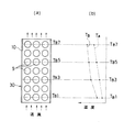
このように複数の電池モジュール9を収容したホルダーケース10は、図2に示すように、外装ケース4内に固定されて電池電源装置1として構成される。この電池電源装置1は、動作中においては送風機5から送風して、ホルダーケース10内に下部方向から空気(媒体)を送り込み、各電池モジュール9を強制冷却する。このとき、送風方向最上流側の電池モジュール9aに比べて下流側の電池モジュール9になるほど、上流側の電池モジュール9と熱交換して温度上昇した空気により冷却されることになるため、最上流側の電池モジュール9aの温度との間に温度差が生じる。電池はその温度により電池容量や充電効率等の電池特性が変化するので、この電池電源装置1のように多数の単電池7を集積して構成した場合に、各単電池7の温度は均等な状態であることが要求される。しかし、送風される空気に最初に触れる最上流側の電池モジュール9aは冷却効果が最も高くなるため、他の電池モジュール9より温度が低い状態となり、電池温度の均等化がなされない状態となる。そこで、図示するように、送風方向の最上流側に位置する電池モジュール9a、9a、9aをPET(ポリエチレンテレフタレート)フィルムにより形成されたフィルム筒2により被覆すると、この電池モジュール9aは送風される空気に直接触れることがなく、フィルム筒2との間に空気層が形成されるため、送風空気による冷却効果が低下する。最上流側の電池モジュール9aにフィルム筒2を被せない状態においては、図4に破線で示すように、他の電池モジュール9との間の温度差が大きくなるが、最上流側の電池モジュール9aにフィルム筒2を被せると、図4に示すように、電池モジュール9aの温度が上昇すると共に、この電池モジュール9aによって送風空気の温度上昇が抑えられることもあって他の電池モジュール9の温度上昇は抑制され、温度差が少ない状態となる。
【0018】
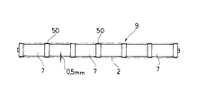
前記電池モジュール9は、図3に示すように、6本の単電池7を接続リング50を介したスポット溶接により機械的に連結すると同時に電気的に直列接続して構成されている。この電池モジュール9上に前記接続リング50の直径を内径とする前記フィルム筒2を被せると、図示するように、フィルム筒2は最も直径が大きくなっている前記接続リング50の部分で支持され、各単電池7の表面との間に約0.5mmの間隔を設けて電池モジュール9を被覆した状態となる。
【0019】
上記構成によれば、送風方向の最上流側の電池モジュール9aの温度が他の位置にある電池モジュール9の温度より極端に低くなることが抑制されるが、全ての電池モジュール9の温度を均等化した状態にはならない。そこで、各電池モジュール9が均等の温度となるように構成した実施形態について次に説明する。
【0020】
図5に示すように、送風方向の上流側にある電池モジュール9にフィルム筒2a〜2eを被せ、各フィルム筒2a〜2eの直径が異なるように設定し、送風方向の上流側にある電池モジュール9になるほど直径の大きなフィルム筒2で被覆されるようにする。直径の大きなフィルム筒2で被覆されるほど電池モジュール9を囲む空気層の厚さが大きくなるため、送風空気による冷却効果が低下する。
【0021】
従って、上流側から下流側に向けて徐々に冷却効率が大きくなる構造となり、送風空気が下流側に行くほどに温度上昇することによる冷却効果の低下が打ち消されるため、送風方向の上流側から下流側に至る全ての電池モジュール9の温度はほぼ均等な状態となる。
【0022】
上記構成において、電池モジュール9に直径の異なるフィルム筒2a〜2eを被せるには、図6に示すように、単電池7、7間を連結する接続リング50上にスペーサ3を取り付け、このスペーサ3の厚さをフィルム筒2の直径に対応して変更することにより、電池モジュール9の表面と所定の間隔を設けてフィルム筒2を被せることができる。
【0023】
前記フィルム筒2は、上記構成による場合、それぞれに直径が異なるフィルム筒2a〜2eとして用意する必要があり、その製造や在庫、運搬等における占有スペースが大きく、また、電池モジュール9の配設位置毎に区別する製造上でも管理が煩雑になり、現実的なものとはいえない。そこで、各直径サイズ毎のフィルム筒2a〜2eを共通サイズの樹脂フィルムから製作できるようにすると、製造コストや管理の手間を低減させることができる。
【0024】
図7(a)に示すように、一辺の長さが最大直径のフィルム筒2aの円周長より長いサイズに形成されたフィルム12を円筒状にカールさせ、大きな直径のフィルム筒2aとして使用するときには、図7(b)に示すように、電池モジュール9上に取り付けられた直径サイズの大きなスペーサ3a上に被せると、所定の直径で電池モジュール9を覆うと共に、端辺でオーバーラップする部分ができるので、このオーバーラップ部分で接合することによりフィルム筒2aとすることができる。また、小さな直径のフィルム筒2eとして使用するときには、図7(c)に示すように、電池モジュール9上に取り付けられた直径サイズの小さいスペーサ3e上に被せると、所定の直径で電池モジュール9を覆うと共に、端辺でオーバーラップする部分が大きくなるので、このオーバーラップ部分で接合することによりフィルム筒2eとすることができる。尚、フィルム12は、その一辺が各フィルム筒2a〜2eを形成する円周長に一定長のオーバーラップ分を加えた長さになるようにして複数種類に容易し、直径の異なる円筒に形成するようにしてもよい。
【0025】
以上説明した構成では、送風方向の各段毎の電池モジュール9に所定の間隔を設けてフィルム筒2を被せるように構成しているが、各段の並列方向での温度条件の良し悪しによってフィルム筒2の直径を変化させ、電池モジュール9の温度が均等になるように調整することもできる。
【0026】
また、以上説明した構成は、電池を冷却することによる温度管理を目的として示したが、寒冷地等における電池電源装置の使用においては、逆に電池を加温することを要する場合があり、そのときには、温風を媒体として同様に温度管理を行うことができる。
【0027】
【発明の効果】
以上の説明の通り本発明によれば、複数の電池を集積したその並列方向に媒体を流通させて電池の温度を調節するとき、媒体の流通方向の上流側にある電池にフィルム筒を被せることにより、上流側にある電池の媒体との熱交換効率が低下して、他の位置にある電池より温度が低くなることが抑制され、複数の電池の温度に極端な差が生じることを防止することができる。また、媒体の流通方向の上流側に位置する電池ほど電池との間の間隔を大きくなるようにしてフィルム筒で覆うことにより、フィルム筒と電池との間に形成される空気層の厚さが異なることによる熱交換効率の差によって複数の電池の温度を均等な状態にすることができる。従って、その温度により特性に変化が生じる電池を集積した組電池の性能を良好な状態に維持することができる。
【図面の簡単な説明】
【図1】実施形態に係る組電池の構成を示す斜視図。
【図2】第1の実施形態による電池の冷却構造を示す断面図。
【図3】電池モジュールの構成を示す側面図。
【図4】第1の実施形態による電池温度の均等化を示すグラフ。
【図5】第2の実施形態による電池の冷却構造を示す側面図。
【図6】電池モジュールに対するフィルム筒の装着構造を示す(a)は断面図、(b)は側面図。
【図7】(a)はフィルム筒を形成する樹脂フィルムの斜視図、(b)は直径大に(c)は直径小に形成して装着した状態を示す断面図。
【図8】電池温度の均等化構造を設けていない場合の(a)は組電池の構成図と、(b)はその電池温度の分布グラフ。
【符号の説明】
2 フィルム筒
3 スペーサ
5 送風機
7 単電池
9、9a 電池モジュール
10 ホルダーケース[0001]
BACKGROUND OF THE INVENTION
The present invention relates to an integrated battery temperature management method for equalizing the temperature of each battery block when a plurality of battery blocks formed by connecting single cells in series are integrated to form an integrated battery having a required output power. And an apparatus for the same.
[0002]
[Prior art]
As is well known, since the electromotive force of the unit cell is only a small voltage of about 1 to 4 V, when a large output power is required, the unit cell formed by the unit cell is connected in series to form a battery block. The battery blocks are connected in series to obtain a desired output voltage. Therefore, when configuring a battery power source with a large output power, a plurality of battery blocks are arranged vertically and horizontally in a holder case to constitute an integrated battery. A battery power source configured by integrating a large number of single cells as described above performs charge / discharge control using a secondary battery, and is always maintained so that required power can be taken out.
[0003]
The temperature of the secondary battery rises due to heat generated by charging / discharging, and if a large number of single cells are integrated, the amount of heat generated is large, and it is necessary to cool in order to suppress the temperature rise. On the other hand, when used in a cold region, if the battery temperature falls below the appropriate temperature, the battery performance may be lowered, and the battery may need to be heated. Further, since the battery characteristics change depending on the temperature of the battery, it is necessary to maintain all the integrated unit cells at a uniform temperature.
[0004]
In order to control the temperature of the integrated battery, as shown in FIG. 8, when the
[0005]
[Problems to be solved by the invention]
However, in the cooling structure of the integrated battery configured as described above, the air temperature Ta is passed between the
[0006]
An object of the present invention is to provide an integrated battery temperature management method and apparatus capable of maintaining the temperature of each battery block constituting an integrated battery in which a plurality of battery blocks are integrated at an equal temperature. is there.
[0007]
[Means for Solving the Problems]
In order to achieve the above object, the temperature management method according to the first invention of the present application comprises a plurality of battery blocks formed by connecting unit cells in series, arranged in parallel in a holder case to constitute an integrated battery, In a temperature management method for an integrated battery in which a medium is forcibly distributed in the parallel direction of the battery blocks in the holder case and the temperature of each battery block is adjusted, a film cylinder is attached to the battery block located upstream in the distribution direction of the medium. And the medium is circulated such that the distance between the film cylinder and the surface of the battery block becomes larger as the battery block is in a position with good heat exchange conditions.
[0008]
According to this temperature management method, since the battery block located on the upstream side in the medium flow direction is covered with the film cylinder, the heat exchange efficiency is lowered. Further, by setting the distance between the film cylinder and the surface of the battery block so that the battery block in a position with good heat exchange conditions becomes larger, the heat exchange efficiency decreases as the battery block increases in distance. Therefore, by adjusting the distance between the film cylinder and the surface of the battery block in accordance with the temperature of the medium and covering the battery block on the upstream side with the film cylinder, the temperature of each battery block is made uniform. It is possible to equalize the changing battery characteristics and configure an integrated battery with good performance.
[0009]
Furthermore, in the temperature management device according to the second invention of the present application, a plurality of battery blocks formed by connecting unit cells in series are arranged in parallel in a holder case to constitute an integrated battery, and the battery in the holder case In the integrated battery temperature control device that cools each battery block by forcibly circulating the medium in the parallel direction of the block, the distance from the surface of the battery block located upstream in the distribution direction of the medium is adjusted. The film cylinder is covered in such a manner that the distance from the surface of the battery block is set to be larger as the battery block is in a position with good heat exchange conditions.
[0010]
According to this configuration, the battery block covered with the film cylinder forms an air layer between the film cylinder and the heat exchange efficiency by the medium is reduced. By setting the heat exchange efficiency to be lower toward the upstream side in the medium flow direction, the temperature difference between the integrated battery blocks can be reduced.
[0011]
In the above configuration, a spacer having a predetermined thickness is disposed on a part of the surface of the battery block, a film cylinder is disposed on the spacer, and the surface of the battery block is covered with the film cylinder. By changing the thickness, the distance between the film cylinder and the surface of the battery block can be adjusted, and the heat exchange efficiency can be adjusted by the thickness of the air layer in the distance.
[0012]
Further, the film cylinder can be configured as a resin film formed in a cylindrical shape, and the heat exchange efficiency can be adjusted by changing the thickness of the air layer by the film cylinders having different diameters.
[0013]
Also, the film cylinder is formed by joining a resin film formed in a longer width than the circumference covering the cylindrical battery block with a predetermined distance from the surface thereof, joined at an overlap portion wound in a cylindrical shape of a predetermined diameter. The cost can be reduced as compared with the case of manufacturing a cylindrical film cylinder, and the occupied space during inventory and transportation can be reduced.
[0014]
The film cylinder is formed by winding a resin film formed in a width longer than the circumference at the maximum interval to cover the cylindrical battery block with a predetermined distance from the surface of the cylindrical cylinder block, and wound around the cylindrical cylinder having a diameter to be attached to the battery block. By forming it, it becomes possible to form a film cylinder having a plurality of types of diameters required by a single type of resin film.
[0015]
DETAILED DESCRIPTION OF THE INVENTION
Hereinafter, an embodiment of the present invention will be described with reference to the accompanying drawings for understanding of the present invention. The following embodiment is an example embodying the present invention, and does not limit the technical scope of the present invention.
[0016]
FIG. 1 shows a configuration of an integrated battery according to an embodiment of the present invention, and shows an embodiment applied to a battery power source of a hybrid vehicle that uses an electric motor and an internal combustion engine as drive sources. In this integrated battery, six unit cells configured as nickel metal hydride secondary batteries are connected in series to form a
[0017]
As shown in FIG. 2, the
[0018]
As shown in FIG. 3, the
[0019]
According to the above configuration, the temperature of the
[0020]
As shown in FIG. 5, the
[0021]
Accordingly, the cooling efficiency gradually increases from the upstream side toward the downstream side, and the decrease in the cooling effect due to the temperature rise as the blown air goes to the downstream side is canceled out. The temperatures of all the
[0022]
In the above configuration, to cover the
[0023]
In the case of the above-described configuration, the
[0024]
As shown in FIG. 7A, a
[0025]
In the configuration described above, the
[0026]
Moreover, although the structure demonstrated above was shown for the purpose of the temperature management by cooling a battery, in use of a battery power supply device in a cold district etc., it may be necessary to heat a battery conversely, In some cases, temperature management can be similarly performed using warm air as a medium.
[0027]
【The invention's effect】
As described above, according to the present invention, when a medium is circulated in a parallel direction in which a plurality of batteries are integrated and the temperature of the battery is adjusted, the battery on the upstream side in the medium distribution direction is covered with a film cylinder. As a result, the efficiency of heat exchange with the battery medium on the upstream side is reduced, and the temperature is suppressed from being lower than that of the battery at other positions, thereby preventing an extreme difference between the temperatures of the plurality of batteries. be able to. In addition, by covering the battery positioned closer to the upstream side in the medium flow direction with the film cylinder so that the distance between the batteries is larger, the thickness of the air layer formed between the film cylinder and the battery is reduced. The temperature of a some battery can be made into an equal state by the difference in the heat exchange efficiency by different. Therefore, it is possible to maintain the performance of the assembled battery in which the batteries whose characteristics change depending on the temperature are integrated.
[Brief description of the drawings]
FIG. 1 is a perspective view showing a configuration of an assembled battery according to an embodiment.
FIG. 2 is a cross-sectional view showing a battery cooling structure according to the first embodiment.
FIG. 3 is a side view showing a configuration of a battery module.
FIG. 4 is a graph showing equalization of battery temperature according to the first embodiment.
FIG. 5 is a side view showing a battery cooling structure according to a second embodiment.
FIGS. 6A and 6B are a cross-sectional view and a side view, respectively, showing a film tube mounting structure for a battery module.
7A is a perspective view of a resin film forming a film cylinder, FIG. 7B is a cross-sectional view showing a state in which the resin film is formed with a large diameter and FIG.
8A is a configuration diagram of an assembled battery when a battery temperature equalization structure is not provided, and FIG. 8B is a distribution graph of the battery temperature.
[Explanation of symbols]
2
Claims (6)
前記媒体の流通方向の上流側に位置する電池ブロックにフィルム筒を被せ、このフィルム筒と電池ブロックの表面との間隔が熱交換条件のよい位置にある電池ブロックほど大きくなるようにして媒体を流通させるようにしたことを特徴とする集積電池の温度管理方法。A plurality of battery blocks formed by connecting unit cells in series are arranged in parallel in a holder case to constitute an integrated battery, and each medium is forcibly distributed in the parallel direction of the battery blocks in the holder case. In the integrated battery temperature management method for adjusting the temperature of the battery block,
Cover the battery block located upstream in the flow direction of the medium with a film cylinder, and distribute the medium so that the distance between the film cylinder and the surface of the battery block is larger as the battery block is in a better heat exchange condition. A temperature management method for an integrated battery, wherein:
前記媒体の流通方向の上流側に位置する電池ブロックに、その表面との間隔を調整できるようにしてフィルム筒を被せ、前記電池ブロック表面との間隔を熱交換条件のよい位置にある電池ブロックほど大きくなるように設定したことを特徴とする集積電池の温度管理装置。A plurality of battery blocks formed by connecting unit cells in series are arranged in parallel in a holder case to constitute an integrated battery, and each medium is forcibly distributed in the parallel direction of the battery blocks in the holder case. In the integrated battery temperature management device that adjusts the temperature of the battery block,
The battery block located on the upstream side of the medium flow direction is covered with a film cylinder so that the distance to the surface of the battery block can be adjusted, and the distance between the battery block surface and the battery block is in a better position for heat exchange. An integrated battery temperature management device, which is set to be large.
Priority Applications (6)
| Application Number | Priority Date | Filing Date | Title |
|---|---|---|---|
| JP24933298A JP4231127B2 (en) | 1998-09-03 | 1998-09-03 | Integrated battery temperature control method and apparatus |
| PCT/JP1999/004813 WO2000014822A1 (en) | 1998-09-03 | 1999-09-03 | Method and apparatus for temperature control of integrated battery |
| DE69942230T DE69942230D1 (en) | 1998-09-03 | 1999-09-03 | METHOD AND DEVICE FOR TEMPERATURE CONTROL OF INTEGRATED BATTERIES |
| CNB998101508A CN1161858C (en) | 1998-09-03 | 1999-09-03 | Method and apparatus for temp. control of integrated battery |
| US09/763,622 US6448741B1 (en) | 1998-09-03 | 1999-09-03 | Temperature control method and structure for a battery pack |
| EP19990940671 EP1115172B1 (en) | 1998-09-03 | 1999-09-03 | Method and apparatus for temperature control of integrated battery |
Applications Claiming Priority (1)
| Application Number | Priority Date | Filing Date | Title |
|---|---|---|---|
| JP24933298A JP4231127B2 (en) | 1998-09-03 | 1998-09-03 | Integrated battery temperature control method and apparatus |
Publications (2)
| Publication Number | Publication Date |
|---|---|
| JP2000082502A JP2000082502A (en) | 2000-03-21 |
| JP4231127B2 true JP4231127B2 (en) | 2009-02-25 |
Family
ID=17191446
Family Applications (1)
| Application Number | Title | Priority Date | Filing Date |
|---|---|---|---|
| JP24933298A Expired - Fee Related JP4231127B2 (en) | 1998-09-03 | 1998-09-03 | Integrated battery temperature control method and apparatus |
Country Status (6)
| Country | Link |
|---|---|
| US (1) | US6448741B1 (en) |
| EP (1) | EP1115172B1 (en) |
| JP (1) | JP4231127B2 (en) |
| CN (1) | CN1161858C (en) |
| DE (1) | DE69942230D1 (en) |
| WO (1) | WO2000014822A1 (en) |
Families Citing this family (59)
| Publication number | Priority date | Publication date | Assignee | Title |
|---|---|---|---|---|
| DE60233895D1 (en) | 2001-11-01 | 2009-11-12 | Honda Motor Co Ltd | BATTERY OPERATED POWER SOURCE DEVICE |
| JP4272387B2 (en) * | 2002-05-22 | 2009-06-03 | パナソニック株式会社 | Battery pack cooling device |
| JP4489369B2 (en) * | 2003-03-26 | 2010-06-23 | パナソニックEvエナジー株式会社 | Battery pack |
| KR100590017B1 (en) * | 2004-11-30 | 2006-06-14 | 삼성에스디아이 주식회사 | Secondary battery module |
| US7604896B2 (en) * | 2005-03-16 | 2009-10-20 | Ford Global Technologies, Llc | High voltage battery assembly for a motor vehicle |
| CN101395781B (en) * | 2005-03-16 | 2011-09-14 | 福特全球技术公司 | Power supply temperature sensor and system |
| KR100880388B1 (en) * | 2005-04-20 | 2009-01-23 | 주식회사 엘지화학 | Housing Member For Battery Module |
| US8816645B2 (en) | 2005-07-20 | 2014-08-26 | Aerovironment, Inc. | Integrated battery unit with cooling and protection expedients for electric vehicles |
| KR101029021B1 (en) * | 2005-12-02 | 2011-04-14 | 주식회사 엘지화학 | Battery Module of High Cooling Efficiency |
| KR100837972B1 (en) * | 2006-11-28 | 2008-06-13 | 현대자동차주식회사 | Cooling or heating apparatus structure of battery modules |
| KR20080072443A (en) * | 2007-02-02 | 2008-08-06 | 삼성에스디아이 주식회사 | Fixing cap by welding and cell module equipped it |
| US20080225483A1 (en) * | 2007-03-15 | 2008-09-18 | Paccar Inc | Frame mounted modular hybrid cooling system |
| JP4529991B2 (en) * | 2007-04-03 | 2010-08-25 | 株式会社デンソー | Battery cooling device |
| KR100974717B1 (en) * | 2007-12-04 | 2010-08-06 | 현대자동차주식회사 | Heater with Cathode Oxygen Depletion fuction for fuel cell vehicle |
| US8628872B2 (en) * | 2008-01-18 | 2014-01-14 | Lg Chem, Ltd. | Battery cell assembly and method for assembling the battery cell assembly |
| US7883793B2 (en) * | 2008-06-30 | 2011-02-08 | Lg Chem, Ltd. | Battery module having battery cell assemblies with alignment-coupling features |
| US8426050B2 (en) * | 2008-06-30 | 2013-04-23 | Lg Chem, Ltd. | Battery module having cooling manifold and method for cooling battery module |
| US8486552B2 (en) * | 2008-06-30 | 2013-07-16 | Lg Chem, Ltd. | Battery module having cooling manifold with ported screws and method for cooling the battery module |
| US9759495B2 (en) * | 2008-06-30 | 2017-09-12 | Lg Chem, Ltd. | Battery cell assembly having heat exchanger with serpentine flow path |
| US9337456B2 (en) * | 2009-04-20 | 2016-05-10 | Lg Chem, Ltd. | Frame member, frame assembly and battery cell assembly made therefrom and methods of making the same |
| US20100275619A1 (en) * | 2009-04-30 | 2010-11-04 | Lg Chem, Ltd. | Cooling system for a battery system and a method for cooling the battery system |
| US8663828B2 (en) * | 2009-04-30 | 2014-03-04 | Lg Chem, Ltd. | Battery systems, battery module, and method for cooling the battery module |
| US8852778B2 (en) * | 2009-04-30 | 2014-10-07 | Lg Chem, Ltd. | Battery systems, battery modules, and method for cooling a battery module |
| US8663829B2 (en) * | 2009-04-30 | 2014-03-04 | Lg Chem, Ltd. | Battery systems, battery modules, and method for cooling a battery module |
| EP2443687B1 (en) | 2009-06-18 | 2017-05-31 | Johnson Controls Advanced Power Solutions LLC | Battery module having a cell tray with thermal management features |
| JP2011044275A (en) * | 2009-08-20 | 2011-03-03 | Sanyo Electric Co Ltd | Power supply device, and vehicle using the same |
| US9147916B2 (en) | 2010-04-17 | 2015-09-29 | Lg Chem, Ltd. | Battery cell assemblies |
| US8469404B2 (en) | 2010-08-23 | 2013-06-25 | Lg Chem, Ltd. | Connecting assembly |
| US8920956B2 (en) | 2010-08-23 | 2014-12-30 | Lg Chem, Ltd. | Battery system and manifold assembly having a manifold member and a connecting fitting |
| US8758922B2 (en) | 2010-08-23 | 2014-06-24 | Lg Chem, Ltd. | Battery system and manifold assembly with two manifold members removably coupled together |
| US8353315B2 (en) | 2010-08-23 | 2013-01-15 | Lg Chem, Ltd. | End cap |
| US9005799B2 (en) | 2010-08-25 | 2015-04-14 | Lg Chem, Ltd. | Battery module and methods for bonding cell terminals of battery cells together |
| CN101944581A (en) * | 2010-09-13 | 2011-01-12 | 天津市捷威动力工业有限公司 | Power battery pack and electric automobile with same |
| US8662153B2 (en) | 2010-10-04 | 2014-03-04 | Lg Chem, Ltd. | Battery cell assembly, heat exchanger, and method for manufacturing the heat exchanger |
| US8288031B1 (en) | 2011-03-28 | 2012-10-16 | Lg Chem, Ltd. | Battery disconnect unit and method of assembling the battery disconnect unit |
| US9178192B2 (en) | 2011-05-13 | 2015-11-03 | Lg Chem, Ltd. | Battery module and method for manufacturing the battery module |
| US9496544B2 (en) | 2011-07-28 | 2016-11-15 | Lg Chem. Ltd. | Battery modules having interconnect members with vibration dampening portions |
| US9105950B2 (en) | 2012-03-29 | 2015-08-11 | Lg Chem, Ltd. | Battery system having an evaporative cooling member with a plate portion and a method for cooling the battery system |
| US9379420B2 (en) | 2012-03-29 | 2016-06-28 | Lg Chem, Ltd. | Battery system and method for cooling the battery system |
| US9605914B2 (en) | 2012-03-29 | 2017-03-28 | Lg Chem, Ltd. | Battery system and method of assembling the battery system |
| US20130273399A1 (en) * | 2012-04-17 | 2013-10-17 | GM Global Technology Operations LLC | Integrated and Optimized Battery Cooling Blower and Manifold |
| US8852781B2 (en) | 2012-05-19 | 2014-10-07 | Lg Chem, Ltd. | Battery cell assembly and method for manufacturing a cooling fin for the battery cell assembly |
| US9722216B2 (en) | 2012-07-18 | 2017-08-01 | General Electric Company | Energy storage device and method |
| US9306199B2 (en) | 2012-08-16 | 2016-04-05 | Lg Chem, Ltd. | Battery module and method for assembling the battery module |
| US9083066B2 (en) | 2012-11-27 | 2015-07-14 | Lg Chem, Ltd. | Battery system and method for cooling a battery cell assembly |
| US9184424B2 (en) | 2013-07-08 | 2015-11-10 | Lg Chem, Ltd. | Battery assembly |
| US9257732B2 (en) | 2013-10-22 | 2016-02-09 | Lg Chem, Ltd. | Battery cell assembly |
| US9444124B2 (en) | 2014-01-23 | 2016-09-13 | Lg Chem, Ltd. | Battery cell assembly and method for coupling a cooling fin to first and second cooling manifolds |
| US10084218B2 (en) | 2014-05-09 | 2018-09-25 | Lg Chem, Ltd. | Battery pack and method of assembling the battery pack |
| US10770762B2 (en) | 2014-05-09 | 2020-09-08 | Lg Chem, Ltd. | Battery module and method of assembling the battery module |
| US10658717B2 (en) * | 2014-09-30 | 2020-05-19 | Cps Technology Holdings Llc | Battery module active thermal management features and positioning |
| US9484559B2 (en) | 2014-10-10 | 2016-11-01 | Lg Chem, Ltd. | Battery cell assembly |
| US9412980B2 (en) | 2014-10-17 | 2016-08-09 | Lg Chem, Ltd. | Battery cell assembly |
| US9786894B2 (en) | 2014-11-03 | 2017-10-10 | Lg Chem, Ltd. | Battery pack |
| US9627724B2 (en) | 2014-12-04 | 2017-04-18 | Lg Chem, Ltd. | Battery pack having a cooling plate assembly |
| FR3050074B1 (en) | 2016-04-07 | 2018-06-22 | Commissariat A L'energie Atomique Et Aux Energies Alternatives | ELECTROCHEMICAL DEVICE, SUCH AS A MICROBATTERY, AND METHOD FOR PRODUCING THE SAME |
| RU172277U1 (en) * | 2016-12-27 | 2017-07-10 | Общество с ограниченной ответственностью "Амулет" | Battery Module |
| DE102018110269A1 (en) * | 2018-04-27 | 2019-10-31 | Airbus Operations Gmbh | Battery holding device and aircraft with such a battery holding device |
| CN110739502A (en) * | 2019-09-08 | 2020-01-31 | 南京金龙新能源汽车研究院有限公司 | thin-wall cavity liquid cooling structure battery module |
Family Cites Families (10)
| Publication number | Priority date | Publication date | Assignee | Title |
|---|---|---|---|---|
| DE3247969A1 (en) * | 1982-12-24 | 1984-06-28 | Brown, Boveri & Cie Ag, 6800 Mannheim | HIGH TEMPERATURE STORAGE BATTERY |
| US5304434A (en) * | 1992-06-15 | 1994-04-19 | Gnb Industrial Battery Co. | Modular cabinet for large-sized sealed lead-acid cells |
| JP3432079B2 (en) * | 1996-06-12 | 2003-07-28 | 松下電器産業株式会社 | Power supply device and heat dissipation method thereof |
| US5879833A (en) | 1996-06-12 | 1999-03-09 | Matsushita Electric Industrial Co., Ltd. | Power supply unit and heat radiation method therefor |
| JPH10106520A (en) | 1996-09-26 | 1998-04-24 | Matsushita Electric Ind Co Ltd | Storage battery power supply device |
| JP3312852B2 (en) | 1996-09-26 | 2002-08-12 | 松下電器産業株式会社 | Battery power supply |
| JP3829391B2 (en) | 1997-03-07 | 2006-10-04 | トヨタ自動車株式会社 | Battery assembly and electric vehicle |
| EP1030390B1 (en) * | 1997-03-24 | 2004-02-04 | Matsushita Electric Industrial Co., Ltd. | Battery power source unit |
| FR2761203B1 (en) * | 1997-03-24 | 1999-05-28 | Alsthom Cge Alcatel | DEVICE FOR MANAGING THE TEMPERATURE OF A BATTERY OF ELECTROCHEMICAL GENERATORS |
| JP3829396B2 (en) | 1997-03-24 | 2006-10-04 | トヨタ自動車株式会社 | Battery power cooling system |
-
1998
- 1998-09-03 JP JP24933298A patent/JP4231127B2/en not_active Expired - Fee Related
-
1999
- 1999-09-03 DE DE69942230T patent/DE69942230D1/en not_active Expired - Lifetime
- 1999-09-03 US US09/763,622 patent/US6448741B1/en not_active Expired - Lifetime
- 1999-09-03 CN CNB998101508A patent/CN1161858C/en not_active Expired - Lifetime
- 1999-09-03 WO PCT/JP1999/004813 patent/WO2000014822A1/en active Application Filing
- 1999-09-03 EP EP19990940671 patent/EP1115172B1/en not_active Expired - Lifetime
Also Published As
| Publication number | Publication date |
|---|---|
| EP1115172A4 (en) | 2004-09-01 |
| JP2000082502A (en) | 2000-03-21 |
| US6448741B1 (en) | 2002-09-10 |
| CN1315062A (en) | 2001-09-26 |
| EP1115172A1 (en) | 2001-07-11 |
| EP1115172B1 (en) | 2010-04-07 |
| CN1161858C (en) | 2004-08-11 |
| WO2000014822A1 (en) | 2000-03-16 |
| DE69942230D1 (en) | 2010-05-20 |
Similar Documents
| Publication | Publication Date | Title |
|---|---|---|
| JP4231127B2 (en) | Integrated battery temperature control method and apparatus | |
| JP4641737B2 (en) | Pack battery | |
| US10340562B2 (en) | Battery pack and heater assembly | |
| KR102253786B1 (en) | Battery Module Comprising Module Case Having Integrally Coupled Heat Sink | |
| JP4625755B2 (en) | Secondary battery module | |
| US7014949B2 (en) | Battery pack and rechargeable vacuum cleaner | |
| JP5307250B2 (en) | Battery module having cooling means, and (medium or large) battery pack including the same | |
| US8999548B2 (en) | Liquid-cooled battery module | |
| JP4440553B2 (en) | Battery pack cooling device | |
| JP5305780B2 (en) | Battery pack for vehicles | |
| JP3235808B2 (en) | Temperature control method for battery of electric vehicle and battery box | |
| JP2008258027A (en) | Collective battery | |
| JPH10255859A (en) | Battery assembly | |
| US20100276120A1 (en) | Temperature adjusting mechanism | |
| JP2007207523A (en) | Battery pack | |
| JP2008047325A (en) | Battery pack | |
| JP2013077432A (en) | Battery module | |
| US20160111760A1 (en) | Power storage module | |
| JPH1154157A (en) | Heat exchanger and battery case | |
| CN112117413A (en) | Clamping plate, battery module and battery pack | |
| JP2003331932A (en) | Assembled battery and battery system | |
| JP2000231911A (en) | Battery system | |
| US11660971B2 (en) | System for arranging and coupling battery cells in a battery module | |
| JPH10106514A (en) | Cylindrical secondary battery and battery pack using this secondary battery | |
| CN114388955B (en) | Cylindrical battery fixing support and hybrid battery thermal management method |
Legal Events
| Date | Code | Title | Description |
|---|---|---|---|
| A621 | Written request for application examination |
Free format text: JAPANESE INTERMEDIATE CODE: A621 Effective date: 20050615 |
|
| RD03 | Notification of appointment of power of attorney |
Free format text: JAPANESE INTERMEDIATE CODE: A7423 Effective date: 20070810 |
|
| A521 | Request for written amendment filed |
Free format text: JAPANESE INTERMEDIATE CODE: A821 Effective date: 20070811 |
|
| RD04 | Notification of resignation of power of attorney |
Free format text: JAPANESE INTERMEDIATE CODE: A7424 Effective date: 20080414 |
|
| TRDD | Decision of grant or rejection written | ||
| A01 | Written decision to grant a patent or to grant a registration (utility model) |
Free format text: JAPANESE INTERMEDIATE CODE: A01 Effective date: 20081111 |
|
| A01 | Written decision to grant a patent or to grant a registration (utility model) |
Free format text: JAPANESE INTERMEDIATE CODE: A01 |
|
| A61 | First payment of annual fees (during grant procedure) |
Free format text: JAPANESE INTERMEDIATE CODE: A61 Effective date: 20081205 |
|
| R150 | Certificate of patent or registration of utility model |
Free format text: JAPANESE INTERMEDIATE CODE: R150 |
|
| FPAY | Renewal fee payment (event date is renewal date of database) |
Free format text: PAYMENT UNTIL: 20111212 Year of fee payment: 3 |
|
| FPAY | Renewal fee payment (event date is renewal date of database) |
Free format text: PAYMENT UNTIL: 20111212 Year of fee payment: 3 |
|
| FPAY | Renewal fee payment (event date is renewal date of database) |
Free format text: PAYMENT UNTIL: 20121212 Year of fee payment: 4 |
|
| FPAY | Renewal fee payment (event date is renewal date of database) |
Free format text: PAYMENT UNTIL: 20121212 Year of fee payment: 4 |
|
| FPAY | Renewal fee payment (event date is renewal date of database) |
Free format text: PAYMENT UNTIL: 20131212 Year of fee payment: 5 |
|
| R250 | Receipt of annual fees |
Free format text: JAPANESE INTERMEDIATE CODE: R250 |
|
| R250 | Receipt of annual fees |
Free format text: JAPANESE INTERMEDIATE CODE: R250 |
|
| R250 | Receipt of annual fees |
Free format text: JAPANESE INTERMEDIATE CODE: R250 |
|
| LAPS | Cancellation because of no payment of annual fees |