JP4857896B2 - Battery pack and vehicle - Google Patents
Battery pack and vehicle Download PDFInfo
- Publication number
- JP4857896B2 JP4857896B2 JP2006132905A JP2006132905A JP4857896B2 JP 4857896 B2 JP4857896 B2 JP 4857896B2 JP 2006132905 A JP2006132905 A JP 2006132905A JP 2006132905 A JP2006132905 A JP 2006132905A JP 4857896 B2 JP4857896 B2 JP 4857896B2
- Authority
- JP
- Japan
- Prior art keywords
- battery
- secondary batteries
- cooling
- assembled battery
- current collector
- Prior art date
- Legal status (The legal status is an assumption and is not a legal conclusion. Google has not performed a legal analysis and makes no representation as to the accuracy of the status listed.)
- Active
Links
Images


Classifications
-
- H—ELECTRICITY
- H01—ELECTRIC ELEMENTS
- H01M—PROCESSES OR MEANS, e.g. BATTERIES, FOR THE DIRECT CONVERSION OF CHEMICAL ENERGY INTO ELECTRICAL ENERGY
- H01M10/00—Secondary cells; Manufacture thereof
- H01M10/04—Construction or manufacture in general
- H01M10/0413—Large-sized flat cells or batteries for motive or stationary systems with plate-like electrodes
- H01M10/0418—Large-sized flat cells or batteries for motive or stationary systems with plate-like electrodes with bipolar electrodes
-
- B—PERFORMING OPERATIONS; TRANSPORTING
- B60—VEHICLES IN GENERAL
- B60L—PROPULSION OF ELECTRICALLY-PROPELLED VEHICLES; SUPPLYING ELECTRIC POWER FOR AUXILIARY EQUIPMENT OF ELECTRICALLY-PROPELLED VEHICLES; ELECTRODYNAMIC BRAKE SYSTEMS FOR VEHICLES IN GENERAL; MAGNETIC SUSPENSION OR LEVITATION FOR VEHICLES; MONITORING OPERATING VARIABLES OF ELECTRICALLY-PROPELLED VEHICLES; ELECTRIC SAFETY DEVICES FOR ELECTRICALLY-PROPELLED VEHICLES
- B60L50/00—Electric propulsion with power supplied within the vehicle
- B60L50/50—Electric propulsion with power supplied within the vehicle using propulsion power supplied by batteries or fuel cells
- B60L50/60—Electric propulsion with power supplied within the vehicle using propulsion power supplied by batteries or fuel cells using power supplied by batteries
- B60L50/64—Constructional details of batteries specially adapted for electric vehicles
-
- H—ELECTRICITY
- H01—ELECTRIC ELEMENTS
- H01M—PROCESSES OR MEANS, e.g. BATTERIES, FOR THE DIRECT CONVERSION OF CHEMICAL ENERGY INTO ELECTRICAL ENERGY
- H01M10/00—Secondary cells; Manufacture thereof
- H01M10/04—Construction or manufacture in general
- H01M10/0431—Cells with wound or folded electrodes
-
- H—ELECTRICITY
- H01—ELECTRIC ELEMENTS
- H01M—PROCESSES OR MEANS, e.g. BATTERIES, FOR THE DIRECT CONVERSION OF CHEMICAL ENERGY INTO ELECTRICAL ENERGY
- H01M10/00—Secondary cells; Manufacture thereof
- H01M10/60—Heating or cooling; Temperature control
- H01M10/61—Types of temperature control
- H01M10/613—Cooling or keeping cold
-
- H—ELECTRICITY
- H01—ELECTRIC ELEMENTS
- H01M—PROCESSES OR MEANS, e.g. BATTERIES, FOR THE DIRECT CONVERSION OF CHEMICAL ENERGY INTO ELECTRICAL ENERGY
- H01M10/00—Secondary cells; Manufacture thereof
- H01M10/60—Heating or cooling; Temperature control
- H01M10/61—Types of temperature control
- H01M10/617—Types of temperature control for achieving uniformity or desired distribution of temperature
-
- H—ELECTRICITY
- H01—ELECTRIC ELEMENTS
- H01M—PROCESSES OR MEANS, e.g. BATTERIES, FOR THE DIRECT CONVERSION OF CHEMICAL ENERGY INTO ELECTRICAL ENERGY
- H01M10/00—Secondary cells; Manufacture thereof
- H01M10/60—Heating or cooling; Temperature control
- H01M10/62—Heating or cooling; Temperature control specially adapted for specific applications
- H01M10/625—Vehicles
-
- H—ELECTRICITY
- H01—ELECTRIC ELEMENTS
- H01M—PROCESSES OR MEANS, e.g. BATTERIES, FOR THE DIRECT CONVERSION OF CHEMICAL ENERGY INTO ELECTRICAL ENERGY
- H01M10/00—Secondary cells; Manufacture thereof
- H01M10/60—Heating or cooling; Temperature control
- H01M10/64—Heating or cooling; Temperature control characterised by the shape of the cells
- H01M10/647—Prismatic or flat cells, e.g. pouch cells
-
- H—ELECTRICITY
- H01—ELECTRIC ELEMENTS
- H01M—PROCESSES OR MEANS, e.g. BATTERIES, FOR THE DIRECT CONVERSION OF CHEMICAL ENERGY INTO ELECTRICAL ENERGY
- H01M10/00—Secondary cells; Manufacture thereof
- H01M10/60—Heating or cooling; Temperature control
- H01M10/65—Means for temperature control structurally associated with the cells
- H01M10/655—Solid structures for heat exchange or heat conduction
- H01M10/6551—Surfaces specially adapted for heat dissipation or radiation, e.g. fins or coatings
-
- H—ELECTRICITY
- H01—ELECTRIC ELEMENTS
- H01M—PROCESSES OR MEANS, e.g. BATTERIES, FOR THE DIRECT CONVERSION OF CHEMICAL ENERGY INTO ELECTRICAL ENERGY
- H01M10/00—Secondary cells; Manufacture thereof
- H01M10/60—Heating or cooling; Temperature control
- H01M10/65—Means for temperature control structurally associated with the cells
- H01M10/655—Solid structures for heat exchange or heat conduction
- H01M10/6556—Solid parts with flow channel passages or pipes for heat exchange
- H01M10/6557—Solid parts with flow channel passages or pipes for heat exchange arranged between the cells
-
- H—ELECTRICITY
- H01—ELECTRIC ELEMENTS
- H01M—PROCESSES OR MEANS, e.g. BATTERIES, FOR THE DIRECT CONVERSION OF CHEMICAL ENERGY INTO ELECTRICAL ENERGY
- H01M4/00—Electrodes
- H01M4/02—Electrodes composed of, or comprising, active material
- H01M4/64—Carriers or collectors
- H01M4/70—Carriers or collectors characterised by shape or form
-
- H—ELECTRICITY
- H01—ELECTRIC ELEMENTS
- H01M—PROCESSES OR MEANS, e.g. BATTERIES, FOR THE DIRECT CONVERSION OF CHEMICAL ENERGY INTO ELECTRICAL ENERGY
- H01M50/00—Constructional details or processes of manufacture of the non-active parts of electrochemical cells other than fuel cells, e.g. hybrid cells
- H01M50/20—Mountings; Secondary casings or frames; Racks, modules or packs; Suspension devices; Shock absorbers; Transport or carrying devices; Holders
- H01M50/204—Racks, modules or packs for multiple batteries or multiple cells
- H01M50/207—Racks, modules or packs for multiple batteries or multiple cells characterised by their shape
- H01M50/209—Racks, modules or packs for multiple batteries or multiple cells characterised by their shape adapted for prismatic or rectangular cells
-
- H—ELECTRICITY
- H01—ELECTRIC ELEMENTS
- H01M—PROCESSES OR MEANS, e.g. BATTERIES, FOR THE DIRECT CONVERSION OF CHEMICAL ENERGY INTO ELECTRICAL ENERGY
- H01M50/00—Constructional details or processes of manufacture of the non-active parts of electrochemical cells other than fuel cells, e.g. hybrid cells
- H01M50/20—Mountings; Secondary casings or frames; Racks, modules or packs; Suspension devices; Shock absorbers; Transport or carrying devices; Holders
- H01M50/249—Mountings; Secondary casings or frames; Racks, modules or packs; Suspension devices; Shock absorbers; Transport or carrying devices; Holders specially adapted for aircraft or vehicles, e.g. cars or trains
-
- H—ELECTRICITY
- H01—ELECTRIC ELEMENTS
- H01M—PROCESSES OR MEANS, e.g. BATTERIES, FOR THE DIRECT CONVERSION OF CHEMICAL ENERGY INTO ELECTRICAL ENERGY
- H01M10/00—Secondary cells; Manufacture thereof
- H01M10/05—Accumulators with non-aqueous electrolyte
- H01M10/052—Li-accumulators
-
- H—ELECTRICITY
- H01—ELECTRIC ELEMENTS
- H01M—PROCESSES OR MEANS, e.g. BATTERIES, FOR THE DIRECT CONVERSION OF CHEMICAL ENERGY INTO ELECTRICAL ENERGY
- H01M10/00—Secondary cells; Manufacture thereof
- H01M10/05—Accumulators with non-aqueous electrolyte
- H01M10/056—Accumulators with non-aqueous electrolyte characterised by the materials used as electrolytes, e.g. mixed inorganic/organic electrolytes
- H01M10/0564—Accumulators with non-aqueous electrolyte characterised by the materials used as electrolytes, e.g. mixed inorganic/organic electrolytes the electrolyte being constituted of organic materials only
- H01M10/0565—Polymeric materials, e.g. gel-type or solid-type
-
- H—ELECTRICITY
- H01—ELECTRIC ELEMENTS
- H01M—PROCESSES OR MEANS, e.g. BATTERIES, FOR THE DIRECT CONVERSION OF CHEMICAL ENERGY INTO ELECTRICAL ENERGY
- H01M10/00—Secondary cells; Manufacture thereof
- H01M10/05—Accumulators with non-aqueous electrolyte
- H01M10/058—Construction or manufacture
- H01M10/0585—Construction or manufacture of accumulators having only flat construction elements, i.e. flat positive electrodes, flat negative electrodes and flat separators
-
- H—ELECTRICITY
- H01—ELECTRIC ELEMENTS
- H01M—PROCESSES OR MEANS, e.g. BATTERIES, FOR THE DIRECT CONVERSION OF CHEMICAL ENERGY INTO ELECTRICAL ENERGY
- H01M10/00—Secondary cells; Manufacture thereof
- H01M10/05—Accumulators with non-aqueous electrolyte
- H01M10/058—Construction or manufacture
- H01M10/0587—Construction or manufacture of accumulators having only wound construction elements, i.e. wound positive electrodes, wound negative electrodes and wound separators
-
- H—ELECTRICITY
- H01—ELECTRIC ELEMENTS
- H01M—PROCESSES OR MEANS, e.g. BATTERIES, FOR THE DIRECT CONVERSION OF CHEMICAL ENERGY INTO ELECTRICAL ENERGY
- H01M10/00—Secondary cells; Manufacture thereof
- H01M10/60—Heating or cooling; Temperature control
- H01M10/65—Means for temperature control structurally associated with the cells
- H01M10/656—Means for temperature control structurally associated with the cells characterised by the type of heat-exchange fluid
- H01M10/6561—Gases
- H01M10/6563—Gases with forced flow, e.g. by blowers
-
- H—ELECTRICITY
- H01—ELECTRIC ELEMENTS
- H01M—PROCESSES OR MEANS, e.g. BATTERIES, FOR THE DIRECT CONVERSION OF CHEMICAL ENERGY INTO ELECTRICAL ENERGY
- H01M10/00—Secondary cells; Manufacture thereof
- H01M10/60—Heating or cooling; Temperature control
- H01M10/65—Means for temperature control structurally associated with the cells
- H01M10/656—Means for temperature control structurally associated with the cells characterised by the type of heat-exchange fluid
- H01M10/6567—Liquids
- H01M10/6568—Liquids characterised by flow circuits, e.g. loops, located externally to the cells or cell casings
-
- H—ELECTRICITY
- H01—ELECTRIC ELEMENTS
- H01M—PROCESSES OR MEANS, e.g. BATTERIES, FOR THE DIRECT CONVERSION OF CHEMICAL ENERGY INTO ELECTRICAL ENERGY
- H01M4/00—Electrodes
- H01M4/02—Electrodes composed of, or comprising, active material
- H01M4/13—Electrodes for accumulators with non-aqueous electrolyte, e.g. for lithium-accumulators; Processes of manufacture thereof
-
- Y—GENERAL TAGGING OF NEW TECHNOLOGICAL DEVELOPMENTS; GENERAL TAGGING OF CROSS-SECTIONAL TECHNOLOGIES SPANNING OVER SEVERAL SECTIONS OF THE IPC; TECHNICAL SUBJECTS COVERED BY FORMER USPC CROSS-REFERENCE ART COLLECTIONS [XRACs] AND DIGESTS
- Y02—TECHNOLOGIES OR APPLICATIONS FOR MITIGATION OR ADAPTATION AGAINST CLIMATE CHANGE
- Y02E—REDUCTION OF GREENHOUSE GAS [GHG] EMISSIONS, RELATED TO ENERGY GENERATION, TRANSMISSION OR DISTRIBUTION
- Y02E60/00—Enabling technologies; Technologies with a potential or indirect contribution to GHG emissions mitigation
- Y02E60/10—Energy storage using batteries
-
- Y—GENERAL TAGGING OF NEW TECHNOLOGICAL DEVELOPMENTS; GENERAL TAGGING OF CROSS-SECTIONAL TECHNOLOGIES SPANNING OVER SEVERAL SECTIONS OF THE IPC; TECHNICAL SUBJECTS COVERED BY FORMER USPC CROSS-REFERENCE ART COLLECTIONS [XRACs] AND DIGESTS
- Y02—TECHNOLOGIES OR APPLICATIONS FOR MITIGATION OR ADAPTATION AGAINST CLIMATE CHANGE
- Y02P—CLIMATE CHANGE MITIGATION TECHNOLOGIES IN THE PRODUCTION OR PROCESSING OF GOODS
- Y02P70/00—Climate change mitigation technologies in the production process for final industrial or consumer products
- Y02P70/50—Manufacturing or production processes characterised by the final manufactured product
-
- Y—GENERAL TAGGING OF NEW TECHNOLOGICAL DEVELOPMENTS; GENERAL TAGGING OF CROSS-SECTIONAL TECHNOLOGIES SPANNING OVER SEVERAL SECTIONS OF THE IPC; TECHNICAL SUBJECTS COVERED BY FORMER USPC CROSS-REFERENCE ART COLLECTIONS [XRACs] AND DIGESTS
- Y02—TECHNOLOGIES OR APPLICATIONS FOR MITIGATION OR ADAPTATION AGAINST CLIMATE CHANGE
- Y02T—CLIMATE CHANGE MITIGATION TECHNOLOGIES RELATED TO TRANSPORTATION
- Y02T10/00—Road transport of goods or passengers
- Y02T10/60—Other road transportation technologies with climate change mitigation effect
- Y02T10/70—Energy storage systems for electromobility, e.g. batteries
Landscapes
- Engineering & Computer Science (AREA)
- Chemical & Material Sciences (AREA)
- General Chemical & Material Sciences (AREA)
- Electrochemistry (AREA)
- Chemical Kinetics & Catalysis (AREA)
- Manufacturing & Machinery (AREA)
- Mechanical Engineering (AREA)
- Aviation & Aerospace Engineering (AREA)
- Transportation (AREA)
- Power Engineering (AREA)
- Sustainable Energy (AREA)
- Sustainable Development (AREA)
- Life Sciences & Earth Sciences (AREA)
- Secondary Cells (AREA)
- Battery Mounting, Suspending (AREA)
- Battery Electrode And Active Subsutance (AREA)
- Connection Of Batteries Or Terminals (AREA)
Description
本発明は、組電池、およびその組電池を備える車両に関し、特に複数のバイポーラ2次電池を積層することにより構成される組電池と、その組電池を備える車両とに関する。 The present invention relates to an assembled battery and a vehicle including the assembled battery, and more particularly to an assembled battery configured by stacking a plurality of bipolar secondary batteries and a vehicle including the assembled battery.
従来の2次電池の冷却構造に関し、たとえば特開2005−71784号公報(特許文献1)は、複数の単電池を直列に積層した積層型電池において複数の集電体に冷却用タブが取り付けられた構造を開示する。複数の単電池の各々は、片面に正極活物質層を、その裏面に負極活物質層を有する集電体に別の集電体をポリマー電解質層を介して直列に接続することにより構成される。この積層型電池では、積層時の厚みの中心にある冷却用タブの放熱効果が最大となり、厚さ方向の両端側に向かって冷却用タブの放熱効果が漸減するように、たとえば冷却用タブの表面積あるいは厚み等が調整される。
上述の積層型電池では冷却用タブが集電体からはみ出る。つまり、上述の積層型電池では冷却用タブを設けることによって電池の幅方向の長さが必然的に大きくなる。しかしながら特開2005−71784号公報(特許文献1)は、このような問題に対する具体的な解決方法を開示していない。 In the stacked battery described above, the cooling tab protrudes from the current collector. That is, in the above-described stacked battery, the length in the width direction of the battery is inevitably increased by providing the cooling tab. However, Japanese Patent Laying-Open No. 2005-71784 (Patent Document 1) does not disclose a specific solution for such a problem.
本発明の目的は、小型化を図りながらその内部を冷却可能な組電池、および、その組電池を備える車両を提供することである。 The objective of this invention is providing the assembled battery which can cool the inside, aiming at size reduction, and a vehicle provided with the assembled battery.
本発明は要約すれば、組電池であって、積層された複数の2次電池を備える。複数の2次電池の各々は、複数の2次電池の積層方向と同一方向に積層された複数のバイポーラ電極を含む。複数のバイポーラ電極の各々の第1の主表面には、正極が形成される。複数のバイポーラ電極の各々の第2の主表面には、負極が形成される。複数の2次電池の各々は、複数のバイポーラ電極のうち隣り合う2つのバイポーラ電極ごとに設けられ、隣り合う2つのバイポーラ電極の一方の正極と、隣り合う2つのバイポーラ電極の他方の負極との間に配置される複数の電解質をさらに含む。組電池は、複数の2次電池の間に冷却媒体を流す複数の冷却通路をさらに備える。 In summary, the present invention is an assembled battery including a plurality of stacked secondary batteries. Each of the plurality of secondary batteries includes a plurality of bipolar electrodes stacked in the same direction as the stacking direction of the plurality of secondary batteries. A positive electrode is formed on the first main surface of each of the plurality of bipolar electrodes. A negative electrode is formed on the second main surface of each of the plurality of bipolar electrodes. Each of the plurality of secondary batteries is provided for each two adjacent bipolar electrodes among the plurality of bipolar electrodes, and includes one positive electrode of the two adjacent bipolar electrodes and the other negative electrode of the two adjacent bipolar electrodes. It further includes a plurality of electrolytes disposed therebetween. The assembled battery further includes a plurality of cooling passages through which a cooling medium flows between the plurality of secondary batteries.
好ましくは、複数の冷却通路は、複数の2次電池のうち隣り合う2つの2次電池ごとにそれぞれ設けられる。隣り合う2つの2次電池の正極同士、または、隣り合う2つの2次電池の負極同士は、複数の冷却通路のうち隣り合う2つの2次電池に対応する冷却通路によって電気的に接続される。 Preferably, the plurality of cooling passages are respectively provided for two adjacent secondary batteries among the plurality of secondary batteries. The positive electrodes of two adjacent secondary batteries or the negative electrodes of two adjacent secondary batteries are electrically connected by a cooling passage corresponding to two adjacent secondary batteries among the plurality of cooling passages. .
より好ましくは、複数の冷却通路には、冷却装置から送られる冷却媒体が流れる。冷却装置は、複数の冷却通路のうちの少なくとも1つの冷却通路に対しては、冷却媒体を第1の向きに流し、複数の冷却通路のうちの他の冷却通路に対しては、第1の向きとは逆の第2の向きに冷却媒体を流す。 More preferably, the cooling medium sent from the cooling device flows through the plurality of cooling passages. The cooling device causes the cooling medium to flow in a first direction with respect to at least one cooling passage of the plurality of cooling passages, and to the first cooling passage with respect to the other cooling passages of the plurality of cooling passages. The cooling medium is caused to flow in a second direction opposite to the direction.
さらに好ましくは、冷却装置は、複数の冷却通路のうち隣り合う2つの冷却通路に対して第1の向きおよび第2の向きに冷却媒体をそれぞれ流す。 More preferably, the cooling device causes the cooling medium to flow in the first direction and the second direction with respect to two adjacent cooling paths among the plurality of cooling paths.
さらに好ましくは、組電池は、複数の2次電池および複数の冷却通路を内部に収容する筐体をさらに備える。筐体の外壁には、複数の放熱フィンが設けられる。 More preferably, the assembled battery further includes a housing that houses therein a plurality of secondary batteries and a plurality of cooling passages. A plurality of heat radiating fins are provided on the outer wall of the housing.
さらに好ましくは、複数の電解質は、固体電解質またはゲル状電解質である。
本発明の他の局面に従うと、組電池であって、2次電池を備える。2次電池は、積層された複数のバイポーラ電極を含む。複数のバイポーラ電極の各々の第1の主表面には、正極が形成される。複数のバイポーラ電極の各々の第2の主表面には、負極が形成される。2次電池は、複数のバイポーラ電極のうち隣り合う2つのバイポーラ電極ごとに設けられ、隣り合う2つのバイポーラ電極の一方の正極と、隣り合う2つのバイポーラ電極の他方の負極との間に配置される複数の電解質をさらに含む。組電池は、複数のバイポーラ電極のうち、積層方向における一方端に配置されるバイポーラ電極に沿って設けられ、冷却媒体を流す冷却通路をさらに備える。
More preferably, the plurality of electrolytes are solid electrolytes or gel electrolytes.
When the other situation of this invention is followed, it is an assembled battery, Comprising: A secondary battery is provided. The secondary battery includes a plurality of stacked bipolar electrodes. A positive electrode is formed on the first main surface of each of the plurality of bipolar electrodes. A negative electrode is formed on the second main surface of each of the plurality of bipolar electrodes. The secondary battery is provided for every two adjacent bipolar electrodes among the plurality of bipolar electrodes, and is disposed between one positive electrode of the two adjacent bipolar electrodes and the other negative electrode of the two adjacent bipolar electrodes. A plurality of electrolytes. The assembled battery further includes a cooling passage that is provided along a bipolar electrode arranged at one end in the stacking direction among the plurality of bipolar electrodes, and allows a cooling medium to flow therethrough.
好ましくは、2次電池と冷却通路との間には、絶縁部材が配置される。2次電池と冷却通路と絶縁部材とは、所定の軸を中心に渦巻状に形成される。 Preferably, an insulating member is disposed between the secondary battery and the cooling passage. The secondary battery, the cooling passage, and the insulating member are formed in a spiral shape around a predetermined axis.
より好ましくは、冷却通路は、予め渦巻状に成型される。
さらに好ましくは、組電池は、複数のバイポーラ電極のうち、積層方向における他方端に配置されるバイポーラ電極に沿って設けられる他の冷却通路と、他の冷却通路に対して、他方端に配置されるバイポーラ電極と反対側に配置される絶縁部材とをさらに備える。2次電池と、冷却通路と、他の冷却通路と、絶縁部材とは、所定の軸を中心に渦巻状に形成される。
More preferably, the cooling passage is formed in a spiral shape in advance.
More preferably, the assembled battery is disposed at the other end of the plurality of bipolar electrodes with respect to another cooling passage provided along the bipolar electrode disposed at the other end in the stacking direction and the other cooling passage. A bipolar electrode and an insulating member disposed on the opposite side. The secondary battery, the cooling passage, the other cooling passage, and the insulating member are formed in a spiral shape around a predetermined axis.
本発明のさらに他の局面に従うと、車両であって、車室内部に配置された分割シートと、上述のいずれかに記載の組電池とを備える。組電池は、分割シートの下に配置される。 According to still another aspect of the present invention, the vehicle includes a split sheet disposed in a vehicle interior and the assembled battery according to any one of the above. The assembled battery is disposed under the split sheet.
本発明によれば、組電池の小型化を図りながら組電池内部の冷却を可能にする。 According to the present invention, it is possible to cool the inside of the assembled battery while reducing the size of the assembled battery.
以下において、本発明の実施の形態について図面を参照して詳しく説明する。なお、図中同一符号は同一または相当部分を示す。 Hereinafter, embodiments of the present invention will be described in detail with reference to the drawings. In the drawings, the same reference numerals indicate the same or corresponding parts.
[実施の形態1]
図1は、本発明の組電池を示す斜視図である。
[Embodiment 1]
FIG. 1 is a perspective view showing an assembled battery of the present invention.
図1を参照して、組電池100は、積層された複数のバイポーラ2次電池4を備える。詳細は後述するが、複数のバイポーラ2次電池4の各々は、複数のバイポーラ電極と、複数の電解質とを含む。複数のバイポーラ電極は、複数のバイポーラ2次電池4の積層方向と同一方向に積層される。複数のバイポーラ電極の各々の第1の主表面には、正極が形成される。複数のバイポーラ電極の各々の第2の主表面には、負極が形成される。つまり、各バイポーラ電極の両面には正極および負極がそれぞれ形成される。
Referring to FIG. 1, the assembled
複数の電解質は、複数のバイポーラ電極のうち隣り合う2つのバイポーラ電極ごとに設けられる。各電解質は、隣り合う2つのバイポーラ電極の一方の正極と、隣り合う2つのバイポーラ電極の他方の負極との間に配置される。 The plurality of electrolytes are provided for every two adjacent bipolar electrodes among the plurality of bipolar electrodes. Each electrolyte is disposed between one positive electrode of two adjacent bipolar electrodes and the other negative electrode of two adjacent bipolar electrodes.
組電池100は、さらに、複数の負極集電板21と、複数の正極集電板23とを備える。図1に示すように複数のバイポーラ2次電池4、複数の負極集電板21、および複数の正極集電板23は、組電池100の下側から上側に向かって正極集電板23、バイポーラ2次電池4、負極集電板21、バイポーラ2次電池4の順に積層される。
The assembled
1つの負極集電板21の上下に配置される2つのバイポーラ2次電池4の各々の負極は、その負極集電板21によって電気的に接続される。1つの正極集電板23の上下に配置される2つのバイポーラ2次電池4の各々の正極は、その正極集電板23によって電気的に接続される。これにより複数のバイポーラ2次電池4は電気的に並列接続される。これにより本実施の形態によれば組電池100の容量を高くすることができる。
The negative electrodes of the two bipolar
バイポーラ2次電池4において、複数のバイポーラ電極の積層方向の長さ(バイポーラ2次電池4の厚み)は、積層方向に直交する平面の長さおよび幅に比較して大幅に短い。一例を示すと、各バイポーラ2次電池4において複数の電極シートの積層方向の長さを1とした場合、上述の平面の幅および長さは10〜15程度となる。各バイポーラ2次電池4に含まれる複数のバイポーラ電極の積層方向と同一方向に複数のバイポーラ2次電池4を積層することで、電池の容量を高めながら組電池のサイズが大きくなることを防ぐことができる。
In the bipolar
複数の負極集電板21および複数の正極集電板23の各々には複数の貫通孔2Aが形成される。複数の貫通孔2Aに冷却媒体(たとえば冷却風や冷却水等)を流すことによって複数のバイポーラ2次電池を冷却することができる。
A plurality of through holes 2 </ b> A are formed in each of the plurality of negative electrode
要するに組電池100において、負極集電板21および正極集電板23は、複数のバイポーラ2次電池のうち積層方向に隣り合う2つのバイポーラ2次電池ごとに配置される。負極集電板21(および正極集電板23)は、その内部に冷却媒体が流れることにより放熱部材としても機能する。
In short, in the assembled
よって本実施の形態においては、組電池100の冷却を行なうために正極集電板23(あるいは負極集電板21)に冷却用タブを接続しなくてもよい。つまり組電池100では正極集電板23(あるいは負極集電板21)からはみ出る部分が存在しない。これにより本実施の形態によれば、組電池100の小型化を図りながら、組電池100の内部を冷却できる。
Therefore, in the present embodiment, in order to cool the assembled
冷却通路に冷却媒体を流した場合には冷却通路と冷却媒体との間で熱交換が行なわれる。よって冷却通路の排出口側の温度が冷却通路の導入口側の温度よりも高くなる。複数の負極集電板21および複数の正極集電板23(以下、「複数の冷却通路」とも称する)の間で冷却媒体の流れる向きを同一とした場合(たとえば図1に示す組電池100の前面から背面に冷却媒体を流す場合)には、複数のバイポーラ2次電池4の間で温度のばらつきが生じやすくなる。
When a cooling medium is caused to flow through the cooling passage, heat is exchanged between the cooling passage and the cooling medium. Accordingly, the temperature on the outlet side of the cooling passage becomes higher than the temperature on the inlet side of the cooling passage. When the flow direction of the cooling medium is the same between the plurality of negative electrode
本実施の形態では、複数の冷却通路のうちの少なくとも1つの冷却通路に対しては、他の冷却通路に冷却媒体が流れる向き(第1の向き)とは逆の向き(第2の向き)に冷却媒体が流れる。これにより複数のバイポーラ2次電池4の間での温度のばらつきを低減することができる。ここで第1の向きを組電池100の前面から背面への向きとした場合には第2の向きは組電池100の背面から前面への向きとなる。
In the present embodiment, for at least one of the plurality of cooling passages, the direction (second direction) opposite to the direction in which the cooling medium flows in the other cooling passage (first direction). The cooling medium flows through. Thereby, temperature variation among the plurality of bipolar
特に図1に示すように、複数の冷却通路同士の間で冷却媒体の流れる向きが第1の向きと第2の向きとで交互になることが好ましい。このように冷却媒体を複数の冷却通路に流すことで複数のバイポーラ2次電池4の間の温度ばらつきをより低減できる。これにより複数のバイポーラ2次電池4の間で温度に依存する特性(たとえばSOC(State of Charge)など)を均一にすることができる。
In particular, as shown in FIG. 1, the direction in which the cooling medium flows between the plurality of cooling passages is preferably alternated between the first direction and the second direction. In this manner, the temperature variation among the plurality of bipolar
図2は、図1の組電池100の一部を取り出して示す図である。
図2において、組電池は3つのバイポーラ2次電池4を含む。各バイポーラ2次電池4から出力される電圧は、たとえば約200Vである。
FIG. 2 is a view showing a part of the assembled
In FIG. 2, the assembled battery includes three bipolar
図2では2つの負極集電板21と2つの正極集電板23とを示す。負極集電板21および正極集電板23はバイポーラ2次電池4の負極および正極にそれぞれ電気的に接続される。2つの負極集電板21は端子T1に接続される。また2つの正極集電板23は端子T2に接続される。これにより組電池の放電時には端子T1,T2間に200Vの電圧が出力される。
FIG. 2 shows two negative
なお組電池の充電時には端子T1,T2間に所定の電圧(たとえば約200V)を印加することにより、各バイポーラ2次電池4が充電される。
When charging the assembled battery, each bipolar
図3は、図2のIII−III線に従う組電池の断面図である。
図3を参照して、複数のバイポーラ2次電池4の各々は、積層された複数の電極シート25を含む。複数の電極シート25の積層方向は複数のバイポーラ2次電池4の積層方向と同じである。
FIG. 3 is a cross-sectional view of the battery pack taken along line III-III in FIG.
Referring to FIG. 3, each of the plurality of bipolar
電極シート25は、正極をなす正極活物質層28と、負極をなす負極活物質層26と、正極活物質層28と負極活物質層26との間に介在する電解質層27とから構成されている。電解質層27は、イオン伝導性を示す材料から形成される層である。電解質層27は、固体電解質であっても良いし、ゲル状電解質であっても良い。電解質層27を介在させることによって、正極活物質層28および負極活物質層26間のイオン伝導がスムーズになり、バイポーラ2次電池4の出力を向上させることができる。
The
複数の電極シート25は、積層方向に隣り合う位置で正極活物質層28と負極活物質層26とが対向するように積層されている。複数の電極シート25間には、それぞれシート状の集電箔29が設けられている。集電箔29の一方の面29bに正極活物質層28が形成され、集電箔29の他方の面29aに負極活物質層26が形成されている。正極活物質層28および負極活物質層26は、たとえばスパッタリングにより集電箔29の表面上に形成されている。
The plurality of
電極シート25の積層方向に隣り合う電解質層27間に配置された、正極活物質層28、集電箔29および負極活物質層26の組が、バイポーラ電極30を構成している。バイポーラ2次電池4では、1つのバイポーラ電極30に、正極をなす正極活物質層28と負極をなす負極活物質層26との双方が形成されている。
A set of the positive electrode
複数の電極シート25は、負極集電板21に最も近い側に配置される電極シート25mと、正極集電板23に最も近い側に配置される電極シート25nとを含む。電極シート25mは、負極集電板21側の端に負極活物質層26が配置されるように設けられている。電極シート25nは、正極集電板23側の端に正極活物質層28が配置されるように設けられている。これにより電極シート25mの負極活物質層26に負極集電板21が接触され、電極シート25nの正極活物質層28に接触するように正極集電板23が積層される。
The plurality of
負極集電板21および正極集電板23には冷却媒体を通すための複数の貫通孔2Aが形成される。
The negative electrode
バイポーラ2次電池4の充放電時には複数のバイポーラ電極30の積層方向に電流が流れる。これによりバイポーラ2次電池4の内部において熱が発生する。一方、複数のバイポーラ電極30の積層方向の両端に冷却通路(正極集電板23および負極集電板21)が設けられる。これらの冷却通路に冷却媒体を流すことで冷却通路の温度が低下する。
When the bipolar
上述のように、複数のバイポーラ電極の積層方向の長さ(バイポーラ2次電池4の厚み)は、積層方向に直交する平面の長さおよび幅に比較して大幅に短い。よって、バイポーラ2次電池4の内部で発生した熱は複数のバイポーラ電極30の積層方向の両端の冷却通路にスムーズに移動する。よってバイポーラ2次電池4を効率よく冷却することができる。
As described above, the length in the stacking direction of the plurality of bipolar electrodes (the thickness of the bipolar secondary battery 4) is significantly shorter than the length and width of the plane orthogonal to the stacking direction. Therefore, the heat generated inside the bipolar
続いて、図3中のバイポーラ2次電池4を構成する各部材について詳細な説明を行なう。集電箔29は、たとえばアルミニウムから形成されている。この場合、集電箔29の表面に設けられる活物質層が固体高分子電解質を含んでも、集電箔29の機械的強度を十分に確保することができる。集電箔29は、銅、チタン、ニッケル、ステンレス鋼(SUS)もしくはこれらの合金等、アルミニウム以外の金属の表面にアルミニウムを被膜することによって形成されても良い。
Subsequently, each member constituting the bipolar
正極活物質層28は、正極活物質および固体高分子電解質を含む。正極活物質層28は、イオン伝導性を高めるための支持塩(リチウム塩)、電子伝導性を高めるための導電助剤、スラリー粘度の調整溶媒としてのNMP(N−メチル−2−ピロリドン)、重合開始剤としてのAIBN(アゾビスイソブチロニトリル)等を含んでも良い。
The positive electrode
正極活物質としては、リチウムイオン2次電池で一般的に用いられる、リチウムと遷移金属との複合酸化物を使用することができる。正極活物質として、たとえば、LiCoO2等のLi・Co系複合酸化物、LiNiO2等のLi・Ni系複合酸化物、スピネルLiMn2O4等のLi・Mn系複合酸化物、LiFeO2等のLi・Fe系複合酸化物などが挙げられる。その他、LiFePO4等の遷移金属とリチウムとのリン酸化合物や硫酸化合物;V2O5、MnO2、TiS2、MoS2、MoO3等の遷移金属酸化物や硫化物;PbO2、AgO、NiOOH等が挙げられる。 As the positive electrode active material, a composite oxide of lithium and a transition metal, which is generally used in a lithium ion secondary battery, can be used. As the positive electrode active material, for example, Li · Co-based composite oxide such as LiCoO 2, Li · Ni-based composite oxide such as LiNiO 2, Li · Mn-based composite oxide such as spinel LiMn 2 O 4, such as LiFeO 2 Examples include Li · Fe-based composite oxides. In addition, phosphoric acid compounds and sulfuric acid compounds of transition metals such as LiFePO 4 and lithium; transition metal oxides and sulfides such as V 2 O 5 , MnO 2 , TiS 2 , MoS 2 , MoO 3 ; PbO 2 , AgO, NiOOH etc. are mentioned.
固体高分子電解質は、イオン伝導性を示す高分子であれば、特に限定されず、たとえば、ポリエチレンオキシド(PEO)、ポリプロピレンオキシド(PPO)、これらの共重合体などが挙げられる。このようなポリアルキレンオキシド系高分子は、LiBF4、LiPF6、LiN(SO2CF3)2、LiN(SO2C2F5)2等のリチウム塩を容易に溶解する。固体高分子電解質は、正極活物質層28および負極活物質層26の少なくとも一方に含まれる。より好ましくは、固体高分子電解質は、正極活物質層28および負極活物質層26の双方に含まれる。
The solid polymer electrolyte is not particularly limited as long as it is a polymer exhibiting ion conductivity, and examples thereof include polyethylene oxide (PEO), polypropylene oxide (PPO), and copolymers thereof. Such a polyalkylene oxide polymer readily dissolves lithium salts such as LiBF 4 , LiPF 6 , LiN (SO 2 CF 3 ) 2 , and LiN (SO 2 C 2 F 5 ) 2 . The solid polymer electrolyte is contained in at least one of the positive electrode
支持塩としては、Li(C2F5SO2)2N、LiBF4、LiPF6、LiN(SO2C2F5)2、もしくはこれらの混合物等を使用することができる。導電助剤としては、アセチレンブラック、カーボンブラック、グラファイト等を使用することができる。 As the supporting salt, Li (C 2 F 5 SO 2 ) 2 N, LiBF 4 , LiPF 6 , LiN (SO 2 C 2 F 5 ) 2 , or a mixture thereof can be used. As the conductive auxiliary agent, acetylene black, carbon black, graphite or the like can be used.
負極活物質層26は、負極活物質および固体高分子電解質を含む。負極活物質層は、イオン伝導性を高めるための支持塩(リチウム塩)、電子伝導性を高めるための導電助剤、スラリー粘度の調整溶媒としてのNMP(N−メチル−2−ピロリドン)、重合開始剤としてのAIBN(アゾビスイソブチロニトリル)等を含んでも良い。
The negative electrode
負極活物質としては、リチウムイオン2次電池で一般的に用いられる材料を使用することができる。但し、固体電解質を使用する場合、負極活物質として、カーボンもしくはリチウムと金属酸化物もしくは金属との複合酸化物を用いることが好ましい。より好ましくは、負極活物質は、カーボンもしくはリチウムと遷移金属との複合酸化物である。さらに好ましくは、遷移金属はチタンである。つまり、負極活物質は、チタン酸化物もしくはチタンとリチウムとの複合酸化物であることがさらに好ましい。 As a negative electrode active material, the material generally used with a lithium ion secondary battery can be used. However, when a solid electrolyte is used, it is preferable to use a composite oxide of carbon or lithium and a metal oxide or metal as the negative electrode active material. More preferably, the negative electrode active material is a composite oxide of carbon or lithium and a transition metal. More preferably, the transition metal is titanium. That is, the negative electrode active material is more preferably titanium oxide or a composite oxide of titanium and lithium.
電解質層27を形成する固体電解質としては、たとえば、ポリエチレンオキシド(PEO)、ポリプロピレンオキシド(PPO)、これらの共重合体等、固体高分子電解質を使用することができる。固体電解質は、イオン伝導性を確保するための支持塩(リチウム塩)を含む。支持塩としては、LiBF4、LiPF6、LiN(SO2CF3)2、LiN(SO2C2F5)2、もしくはこれらの混合物等を使用することができる。
As the solid electrolyte for forming the
さらに、正極活物質層28、負極活物質層26および電解質層27を形成する材料の具体例を表1から表3に示す。表1は、電解質層27が有機系固体電解質である場合の具体例を示し、表2は、電解質層27が無機系固体電解質である場合の具体例を示し、表3は、電解質層27がゲル状電解質である場合の具体例を示す。
Further, specific examples of materials for forming the positive electrode

多くの場合、2次電池に用いられる電解質は液体である。たとえば鉛蓄電池の場合には電解液に稀硫酸が用いられる。このような2次電池では電解質、正極、負極は密閉された袋あるいはケース等に収納されるので、2次電池の内部に生じた熱は一旦容器に伝達され、容器から外部に放出される。つまり、このような2次電池では電解質(電解液)を収納する容器が存在するために、2次電池の内部における冷却を効率的に行なうことは容易ではない。 In many cases, the electrolyte used in the secondary battery is a liquid. For example, in the case of a lead storage battery, dilute sulfuric acid is used as the electrolyte. In such a secondary battery, the electrolyte, the positive electrode, and the negative electrode are housed in a sealed bag or case, so that heat generated inside the secondary battery is once transmitted to the container and released from the container to the outside. That is, in such a secondary battery, there is a container for storing an electrolyte (electrolytic solution), and thus it is not easy to efficiently cool the inside of the secondary battery.
これに対し、本実施の形態ではバイポーラ2次電池4の電解質は固体またはゲル状であるので、電解質を収納するための容器は存在しない。よって、2次電池の内部の内部に生じた熱は冷却通路(つまり負極集電板21および正極集電板23)にスムーズに伝達される。よって本実施の形態によれば組電池の内部を効率的に冷却することが可能になる。
On the other hand, in the present embodiment, since the electrolyte of the bipolar
また、正極集電板23および負極集電板21はある程度の強度を有する。本実施の形態では複数のバイポーラ2次電池4の各々は正極集電板23および負極集電板21により挟まれる。正極集電板23および負極集電板21をバイポーラ2次電池4に挟んだときに正極集電板23とバイポーラ2次電池4との隙間、あるいは負極集電板21とバイポーラ2次電池4との隙間をなくすことができる。これによって組電池100の強度を確保することができる。
Further, the positive electrode
続いて、図1〜図3に示す組電池の適用例、および、組電池の冷却方法の具体例について説明する。 Then, the application example of the assembled battery shown in FIGS. 1-3 and the specific example of the cooling method of an assembled battery are demonstrated.
図4は、本発明による組電池を搭載した自動車の実施の形態を示す断面模式図である。
図5は、図4に示した自動車の平面透視模式図である。
FIG. 4 is a schematic cross-sectional view showing an embodiment of an automobile equipped with the assembled battery according to the present invention.
FIG. 5 is a schematic plan view of the automobile shown in FIG.
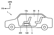
図4および図5を参照して、本発明による自動車1はたとえば充放電可能な電源を動力源とする電気自動車、あるいは、ガソリンエンジンやディーゼルエンジン等の内燃機関と、充放電可能な電源とを動力源とするハイブリッド車両等である。図1〜図3に示す組電池100はこれらの自動車に電源として搭載されている。
Referring to FIGS. 4 and 5, an
自動車1はその搭乗空間(車室)50内において、フロントシート12a,12b(図5参照)とリアシート6とが配置されている。搭乗空間50内において、フロントシート12a下に、図1〜図3に示す組電池100および冷却機構を含む電池パック120が配置されている。電池パック120は、フロントシート12a,12b下に配置されたカバー5および床面200により囲まれた状態となっている。フロントシート12a,12bは本発明の車両が備える「分割シート」に対応する。
In the
なお電池パック120はフロントシート12b下に配置されていてもよい。フロントシート12a,12bの下は自動車1の他の部分に比較して電池パック120を収納する空間を確保しやすい。また多くの場合、車体は、衝突時につぶれる部分と、つぶれずに乗員を保護する部分から構成されている。つまりフロントシート12a(あるいはフロントシート12b)の下に電池パック120を配置することにより車体が強い衝撃を受けた場合にも組電池を衝撃から保護できる。
The
なお図4における矢印UPRで示す方向は自動車1の天井方向(上方)を示し、矢印FRで示した方向は自動車1の前方方向(進行方向)を示す。また、図5における矢印LHで示す方向は、自動車1の車両左側の方向(左側側面方向)を示す。
Note that the direction indicated by the arrow UPR in FIG. 4 indicates the ceiling direction (upward) of the
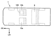
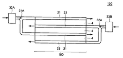
図6は、図4および図5の電池パック120の構成を模式的に示す上面図である。
図7は、図6の電池パック120の構成を模式的に示す側面図である。
FIG. 6 is a top view schematically showing the configuration of the
FIG. 7 is a side view schematically showing the configuration of the
図6および図7を参照して、電池パック120は、組電池100と、吸気ダクト31A,32Aと、排気ダクト31B,32Bと、吸気ファン33A,33Bとを含む。なお図が煩雑になるのを防ぐため図7では排気ダクト31B,32Bは示していない。
Referring to FIGS. 6 and 7,
吸気ファン33A,33Bは、吸気ダクト31A,32Aにそれぞれ接続される。吸気ファン33Aが動作すると、吸気ダクト31Aを介して冷却風が貫通孔2Aに導入され、排気ダクト31Bから冷却風が排出される。吸気ファン33Bが動作すると、吸気ダクト32Aを介して冷却風が貫通孔2Aに導入され、排気ダクト32Bから冷却風が排出される。
The
ここで図7に示すように、負極集電板21に対しては吸気ファン33Aから吸気ダクト31Aを介して冷却風が導入される。一方、正極集電板23の内部の冷却通路に対しては吸気ファン33Bから吸気ダクト32Aを介して冷却風が導入される。負極集電板21および正極集電板23は複数のバイポーラ2次電池4の積層方向に沿って交互に配置される。よって複数のバイポーラ2次電池4の積層方向に沿って隣り合う冷却通路間で冷却風の流れる方向を互いに逆向きとすることができる。なお、吸気ファン33A,33Bに代えて1台の吸気ファンから冷却風が負極集電板21および正極集電板23に送られるように構成されていてもよい。
Here, as shown in FIG. 7, cooling air is introduced into the negative electrode
以上のように実施の形態1によれば、組電池の小型化を図りながら組電池の内部の冷却を可能にする。 As described above, according to the first embodiment, it is possible to cool the inside of the assembled battery while reducing the size of the assembled battery.
[実施の形態2]
図8は、実施の形態2の組電池を示す図である。
[Embodiment 2]
FIG. 8 is a diagram illustrating the assembled battery of the second embodiment.
図8を参照して、組電池100は筐体101と積層型電池110とを備える。積層型電池110は筐体101の内部に収容される。なお、図8に示す積層型電池110は実施の形態1における組電池100と同様の構成を有し、複数のバイポーラ2次電池および複数の冷却通路を備える。よって図8に示す積層型電池110の構成に関する以後の説明は繰返さない。実施の形態2によれば積層型電池110を筐体101に収納することによって実施の形態1の組電池よりも剛性を強化することができる。
With reference to FIG. 8, the assembled
筐体101の外壁には複数の放熱フィン102が設けられる。これにより実施の形態2によれば積層型電池110の内部を冷却できるだけでなく、積層型電池110の外部も冷却できるので、組電池100の冷却性能を全体的に高めることができる。
A plurality of
積層型電池110は複数のバイポーラ2次電池の積層方向に沿って加圧された状態で筐体101の内部に収納され、積層型電池110に対して上下に位置する筐体101の2つの内壁により挟まれる。これにより積層型電池110を拘束することが可能になる。なお、図8には示さないが積層型電池110の表面は絶縁フィルムで覆われる。
積層型電池110の充放電時には、バイポーラ2次電池の内部で電子・イオンの移動が行なわれる。充電時にはバイポーラ2次電池は複数のバイポーラ電極の積層方向に膨張する(膨張したバイポーラ2次電池は放電時に元の状態に戻る)。充放電を繰り返し行なうと、電極間に隙間が生じ、内部抵抗が変化することによって、電池性能が劣化するおそれがある。
At the time of charging / discharging of the stacked
実施の形態2では、筐体101が積層型電池110の拘束部材となる。これにより、電極に生じる寸法変化のばらつきを小さく抑え、電池性能の劣化を抑制できる。また、実施の形態2によれば、たとえば拘束プレートや拘束バンド等の部材を用いずに電池を拘束できる。
In the second embodiment, the
[実施の形態3]
図9は、実施の形態3の組電池の全体を示す斜視図である。
[Embodiment 3]
FIG. 9 is a perspective view showing the entire assembled battery of the third embodiment.
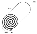
図9を参照して、組電池100Aは、バイポーラ2次電池4Aと、絶縁フィルム24と、冷却通路2Bとを備える。絶縁フィルム24はバイポーラ2次電池4と冷却通路2Bとの間に設けられる。冷却通路2Bの内部には冷却媒体を流すための複数の貫通孔2Aが形成される。放熱性をよくするために冷却通路2Bは金属で形成されていることが好ましい。
Referring to FIG. 9, the assembled
組電池100Aの形状は中心軸41に沿って延びる円柱である。組電池100Aは中心軸41に直交する平面で切断した場合の断面形状が円形となるように形成されている。ただし組電池100Aは、その断面形状が長円または楕円になるように形成されていてもよい。
The shape of the assembled
また、組電池100Aの冷却は、たとえば冷却ファン(図9には示さず)から送られる冷却風を冷却通路2Bの貫通孔2Aに通すことによって行なわれる。
The assembled
図10は、図9に示す組電池100Aの製造方法の一例を示す斜視図である。
図10を参照して、バイポーラ2次電池4Aおよび絶縁フィルム24は複数回、巻回される。バイポーラ2次電池4Aおよび絶縁フィルム24は略矩形の薄膜形状を有する。一方、冷却通路2Bは、金型等によって図9に示す形状(中心軸41に対して渦巻き状)に予め形成されている。この冷却通路2Bに巻回されたバイポーラ2次電池4および絶縁フィルム24を挿入することによって組電池100Aが作製される。
FIG. 10 is a perspective view showing an example of a method for manufacturing the assembled
Referring to FIG. 10, bipolar
なお、冷却通路2Bをバイポーラ2次電池4Aおよび絶縁フィルム24とともに巻くことによって組電池100Aが作製されてもよい。ただし組電池100Aの強度を高くするためには、予め渦巻き状に形成された冷却通路を用いるほうが好ましい。
The assembled
図11は、図10中の2点鎖線XIで囲まれた範囲を拡大して示す断面図である。
図11および図3を参照して、バイポーラ2次電池4Aは負極集電板21と正極集電板23とをさらに備える点でバイポーラ2次電池4と異なる。なおバイポーラ2次電池4Aの他の部分の構成はバイポーラ2次電池4の対応する部分の構成と同様であるので以後の説明は繰返さない。
FIG. 11 is an enlarged cross-sectional view of a range surrounded by a two-dot chain line XI in FIG.
Referring to FIGS. 11 and 3, bipolar
複数の電極シート25は、複数の電極シート25が巻回された場合に、最も内周側に配置される電極シート25mと、最も外周側に配置される電極シート25nとを含む。電極シート25mは、その内周側の端に負極活物質層26が配置されるように設けられている。電極シート25nは、その外周側の端に正極活物質層28が配置されるように設けられている。電極シート25mの負極活物質層26に接触するように負極集電板21が積層されている。電極シート25nの正極活物質層28に接触するように正極集電板23が積層される。
When the plurality of
絶縁フィルム24は正極集電板23に接触するように設けられる(図11では絶縁フィルム24は正極集電板23に接触した状態を示す)。なお、絶縁フィルム24の外側には冷却通路2Bが設けられる。つまり、実施の形態3においては複数のバイポーラ電極30のうち、複数のバイポーラ電極の積層方向における一方端に配置されるバイポーラ電極30に沿って冷却通路2Bが設けられる。
The insulating
また、図9に示すように組電池を作製した際に、絶縁フィルム24によって、正極集電板23と負極集電板21との短絡、すなわち正極集電板23と負極集電板21とが冷却通路2Bによって電気的に接続されることが防止される。
Further, when the assembled battery is manufactured as shown in FIG. 9, the insulating
なお負極集電板21および正極集電板23はバイポーラ2次電池4Aに含まれていなくてもよい。
The negative electrode
上述のようにバイポーラ2次電池4Aは薄膜状である。薄膜の長さを長くするほど電池の容量を大きくすることができる。実施の形態3によれば、薄膜を巻くことによって小型でありながら容量が大きい電池を実現できる。また、実施の形態1におけるバイポーラ2次電池を製造するには、図10に示す薄膜を所定の大きさに切断して積層することが必要になるが、実施の形態3の組電池は実施の形態1の組電池に比較して製造が容易になる。
As described above, the bipolar
また組電池100Aにおいて中心軸41に近い部分においても、冷却通路2Bに冷却媒体を流すことで放熱が促進される。すなわち実施の形態3によればバイポーラ2次電池を巻回することによって構成された組電池に対して適切な冷却を行なうことができる。
Further, even in the portion of the assembled
このように実施の形態3によれば組電池を小型化しながら組電池内部の冷却を適切に行なうことができる。 As described above, according to the third embodiment, the inside of the assembled battery can be appropriately cooled while downsizing the assembled battery.
[実施の形態4]
図12は、実施の形態4の組電池の全体を示す斜視図である。
[Embodiment 4]
FIG. 12 is a perspective view showing the entire assembled battery of the fourth embodiment.
図12および図9を参照して、組電池100Bと組電池100Aとの相違点を説明する。まず組電池100Bは冷却通路2Cをさらに備える。さらに組電池100Bにおいて冷却通路2Bと冷却通路2Cとの間には絶縁フィルム24が設けられる。これらの点で組電池100Bは組電池100Aと異なる。組電池100Bの他の部分については組電池100Aの対応する部分と同様であるので以後の説明は繰返さない。
The difference between the assembled
また、バイポーラ2次電池4Aの断面の構造は図11に示す構造と同様であるので以後の説明は繰返さない。実施の形態4においては、図11に示すバイポーラ2次電池4の正極集電板23の外側に冷却通路2Bが設けられ、負極集電板21の外側に冷却通路2Cが設けられる。
Since the structure of the cross section of bipolar
つまり、実施の形態4においては複数のバイポーラ電極30のうち、複数のバイポーラ電極の積層方向における一方端に配置されるバイポーラ電極30に沿って冷却通路2Bが設けられ、他方端に配置されるバイポーラ電極30に沿って冷却通路2Cが設けられる。
That is, in the fourth embodiment, among the plurality of
なお、組電池100Bの冷却は、たとえば冷却ファン(図12には示さず)から送られる冷却風を冷却通路2B,2Cに通すことによって行なわれる。
The assembled
また、組電池100Bの製造方法は図10に示す組電池の製造方法と同様である。予め冷却通路2B,2Cおよび絶縁フィルム24を一体化して渦巻状に形成する。次に薄膜状のバイポーラ2次電池4Aが複数回、巻回される。そして図12に示す冷却通路2B,2Cの隙間にバイポーラ2次電池4Aを挿入することで組電池100Bが作製される。なお、冷却通路2B,2C、絶縁フィルム24、およびバイポーラ2次電池4Aを重ねて巻くことにより組電池100Bを作製してもよい。
Moreover, the manufacturing method of the assembled
実施の形態4において正極集電板23は冷却通路2Bに直接接する。一方、実施の形態3においては正極集電板23と冷却通路2Bとの間には絶縁フィルム24が設けられる。つまり実施の形態4では集電板と冷却通路との間に絶縁フィルムが存在しないため実施の形態3よりも組電池の放熱性を高めることができる。なお、実施の形態3、実施の形態4ともに負極集電板21は冷却通路(実施の形態3の場合には冷却通路2Bであり、実施の形態4の場合には冷却通路2Cである)に接する。
In the fourth embodiment, positive electrode
以上のように実施の形態4によれば実施の形態3よりも組電池の放熱性を高めることができる。 As described above, according to the fourth embodiment, the heat dissipation of the assembled battery can be improved as compared with the third embodiment.
今回開示された実施の形態はすべての点で例示であって制限的なものではないと考えられるべきである。本発明の範囲は上記した説明ではなくて特許請求の範囲によって示され、特許請求の範囲と均等の意味および範囲内でのすべての変更が含まれることが意図される。 The embodiment disclosed this time should be considered as illustrative in all points and not restrictive. The scope of the present invention is defined by the terms of the claims, rather than the description above, and is intended to include any modifications within the scope and meaning equivalent to the terms of the claims.
1 自動車、2A 貫通孔、2B,2C 冷却通路、4,4A バイポーラ2次電池、5 カバー、6 リアシート、12a,12b フロントシート、21 負極集電板、23 正極集電板、24 絶縁フィルム、25,25m,25n 電極シート、26 負極活物質層、27 電解質層、28 正極活物質層、29 集電箔、29a,29b 面、30 バイポーラ電極、31A,32A 吸気ダクト、31B,32B 排気ダクト、33A,33B 吸気ファン、41 中心軸、50 搭乗空間、100,100A,100B 組電池、101 筐体、102 放熱フィン、110 積層型電池、120 電池パック、200 床面、T1,T2 端子。 1 automobile, 2A through hole, 2B, 2C cooling passage, 4, 4A bipolar secondary battery, 5 cover, 6 rear sheet, 12a, 12b front sheet, 21 negative current collector, 23 positive current collector, 24 insulating film, 25 25m, 25n Electrode sheet, 26 Negative electrode active material layer, 27 Electrolyte layer, 28 Positive electrode active material layer, 29 Current collector foil, 29a, 29b surface, 30 Bipolar electrode, 31A, 32A Intake duct, 31B, 32B Exhaust duct, 33A , 33B Intake fan, 41 central axis, 50 boarding space, 100, 100A, 100B battery pack, 101 housing, 102 heat radiation fin, 110 stacked battery, 120 battery pack, 200 floor, T1, T2 terminals.
Claims (5)
前記複数の2次電池の各々は、
前記複数の2次電池の積層方向と同一方向に積層された複数のバイポーラ電極を含み、
前記複数のバイポーラ電極の各々の第1の主表面には、正極が形成され、
前記複数のバイポーラ電極の各々の第2の主表面には、負極が形成され、
前記複数のバイポーラ電極のうち隣り合う2つのバイポーラ電極ごとに設けられ、前記隣り合う2つのバイポーラ電極の一方の前記正極と、前記隣り合う2つのバイポーラ電極の他方の前記負極との間に配置される複数の電解質をさらに含み、
前記複数の2次電池のうち、少なくとも1対の隣り合う第1および第2の2次電池の間に、冷却媒体が流れる第1の冷却通路を形成するように配置される放熱部材と、
前記第2の2次電池と、前記複数の2次電池のうち前記第2の2次電池に対して前記第1の2次電池と反対側に位置し、かつ、前記第2の2次電池と隣り合う第3の2次電池との間に、前記冷却媒体が流れる第2の冷却通路を形成するように配置される他の放熱部材とをさらに備え、
前記放熱部材は、前記冷却媒体を供給する冷却装置に対して、前記冷却装置からの前記冷却媒体が第1の冷却通路を第1の向きに流れるように配置され、
前記他の放熱部材は、前記冷却装置に対して、前記冷却装置からの前記冷却媒体が、前記第2の冷却通路を前記第1の向きと逆の第2の向きに流れるように配置される、組電池。 A plurality of secondary batteries stacked,
Each of the plurality of secondary batteries is
Including a plurality of bipolar electrodes stacked in the same direction as the stacking direction of the plurality of secondary batteries,
A positive electrode is formed on the first main surface of each of the plurality of bipolar electrodes,
A negative electrode is formed on the second main surface of each of the plurality of bipolar electrodes,
It is provided for every two adjacent bipolar electrodes among the plurality of bipolar electrodes, and is arranged between one positive electrode of the two adjacent bipolar electrodes and the other negative electrode of the two adjacent bipolar electrodes. A plurality of electrolytes,
A heat dissipating member arranged to form a first cooling passage through which a cooling medium flows between at least one pair of adjacent first and second secondary batteries among the plurality of secondary batteries;
The second secondary battery and the second secondary battery that are located on the opposite side of the first secondary battery with respect to the second secondary battery among the plurality of secondary batteries. And a third secondary battery adjacent to each other and another heat dissipating member arranged so as to form a second cooling passage through which the cooling medium flows,
The heat radiating member is arranged such that the cooling medium from the cooling device flows in a first direction through the first cooling passage with respect to the cooling device that supplies the cooling medium,
The other heat dissipating member is disposed with respect to the cooling device such that the cooling medium from the cooling device flows through the second cooling passage in a second direction opposite to the first direction. , Battery pack.
前記第1および第2の2次電池の前記正極同士、または、前記第1および第2の2次電池の前記負極同士は、前記放熱部材によって電気的に接続され、
前記第2および第3の2次電池の前記正極同士、または、前記第2および第3の2次電池の前記負極同士は、前記他の放熱部材によって電気的に接続される、請求項1に記載の組電池。 The heat dissipation member and the other heat dissipation member have conductivity,
The positive electrodes of the first and second secondary batteries or the negative electrodes of the first and second secondary batteries are electrically connected by the heat dissipation member ,
The positive electrodes of the second and third secondary batteries or the negative electrodes of the second and third secondary batteries are electrically connected by the other heat dissipation member. The assembled battery as described.
前記筐体の外壁には、複数の放熱フィンが設けられる、請求項1または2に記載の組電池。 A housing that accommodates the plurality of secondary batteries , the heat dissipation member, and the other heat dissipation member ;
The assembled battery according to claim 1, wherein a plurality of heat radiation fins are provided on an outer wall of the housing.
請求項1から4のいずれか1項に記載の組電池とを備え、
前記組電池は、前記シートの下に配置される、車両。 A sheet over bets placed inside the cabin,
The assembled battery according to any one of claims 1 to 4 ,
The battery pack is arranged below the previous carboxymethyl over preparative vehicle.
Priority Applications (5)
| Application Number | Priority Date | Filing Date | Title |
|---|---|---|---|
| JP2006132905A JP4857896B2 (en) | 2006-05-11 | 2006-05-11 | Battery pack and vehicle |
| PCT/JP2007/058385 WO2007132621A1 (en) | 2006-05-11 | 2007-04-11 | Assembly battery, and vehicle |
| US12/294,749 US7997367B2 (en) | 2006-05-11 | 2007-04-11 | Assembled battery and vehicle |
| EP07741821A EP2017918B1 (en) | 2006-05-11 | 2007-04-11 | Assembly battery, and vehicle with assembly battery |
| CN2007800158920A CN101438454B (en) | 2006-05-11 | 2007-04-11 | Assembly battery, and vehicle |
Applications Claiming Priority (1)
| Application Number | Priority Date | Filing Date | Title |
|---|---|---|---|
| JP2006132905A JP4857896B2 (en) | 2006-05-11 | 2006-05-11 | Battery pack and vehicle |
Publications (3)
| Publication Number | Publication Date |
|---|---|
| JP2007305425A JP2007305425A (en) | 2007-11-22 |
| JP2007305425A5 JP2007305425A5 (en) | 2008-10-16 |
| JP4857896B2 true JP4857896B2 (en) | 2012-01-18 |
Family
ID=38693721
Family Applications (1)
| Application Number | Title | Priority Date | Filing Date |
|---|---|---|---|
| JP2006132905A Active JP4857896B2 (en) | 2006-05-11 | 2006-05-11 | Battery pack and vehicle |
Country Status (5)
| Country | Link |
|---|---|
| US (1) | US7997367B2 (en) |
| EP (1) | EP2017918B1 (en) |
| JP (1) | JP4857896B2 (en) |
| CN (1) | CN101438454B (en) |
| WO (1) | WO2007132621A1 (en) |
Cited By (1)
| Publication number | Priority date | Publication date | Assignee | Title |
|---|---|---|---|---|
| US10559843B2 (en) | 2016-03-15 | 2020-02-11 | Kabushiki Kaisha Toshiba | Non-aqueous electrolyte battery, non-aqueous electrolyte battery pack, and vehicle |
Families Citing this family (73)
| Publication number | Priority date | Publication date | Assignee | Title |
|---|---|---|---|---|
| JP4839955B2 (en) * | 2006-05-11 | 2011-12-21 | トヨタ自動車株式会社 | Battery pack and vehicle |
| JP4857896B2 (en) * | 2006-05-11 | 2012-01-18 | トヨタ自動車株式会社 | Battery pack and vehicle |
| JP4692556B2 (en) * | 2008-02-12 | 2011-06-01 | トヨタ自動車株式会社 | All-solid lithium secondary battery |
| US8486552B2 (en) | 2008-06-30 | 2013-07-16 | Lg Chem, Ltd. | Battery module having cooling manifold with ported screws and method for cooling the battery module |
| US9759495B2 (en) | 2008-06-30 | 2017-09-12 | Lg Chem, Ltd. | Battery cell assembly having heat exchanger with serpentine flow path |
| KR101084079B1 (en) * | 2008-12-09 | 2011-11-16 | 삼성에스디아이 주식회사 | Rechargeable battery and electrode assembly used thereof |
| FR2940632B1 (en) * | 2008-12-30 | 2011-08-19 | Renault Sas | DEVICE FOR COOLING THE BATTERIES OF A PARTICULARLY ELECTRIC VEHICLE AND VEHICLE EQUIPPED WITH SUCH A DEVICE |
| US8357469B2 (en) | 2009-01-21 | 2013-01-22 | Advanced Battery Concepts, LLC | Bipolar battery assembly |
| US8403030B2 (en) | 2009-04-30 | 2013-03-26 | Lg Chem, Ltd. | Cooling manifold |
| US8663829B2 (en) | 2009-04-30 | 2014-03-04 | Lg Chem, Ltd. | Battery systems, battery modules, and method for cooling a battery module |
| US8399118B2 (en) * | 2009-07-29 | 2013-03-19 | Lg Chem, Ltd. | Battery module and method for cooling the battery module |
| US8399119B2 (en) | 2009-08-28 | 2013-03-19 | Lg Chem, Ltd. | Battery module and method for cooling the battery module |
| DE102009040814A1 (en) * | 2009-09-10 | 2011-03-17 | Behr Gmbh & Co. Kg | Method for producing an energy storage holder for a vehicle |
| DE102010007633A1 (en) * | 2010-02-05 | 2011-08-11 | Dr. Ing. h.c. F. Porsche Aktiengesellschaft, 70435 | Vehicle with electric drive device |
| US8662153B2 (en) | 2010-10-04 | 2014-03-04 | Lg Chem, Ltd. | Battery cell assembly, heat exchanger, and method for manufacturing the heat exchanger |
| JP5804323B2 (en) | 2011-01-07 | 2015-11-04 | 株式会社Gsユアサ | Power storage element and power storage device |
| EP2752934B1 (en) * | 2011-08-30 | 2018-10-17 | Toyota Jidosha Kabushiki Kaisha | Vehicle |
| US10615393B2 (en) | 2011-10-24 | 2020-04-07 | Advanced Battery Concepts, LLC | Bipolar battery assembly |
| US9685677B2 (en) | 2011-10-24 | 2017-06-20 | Advanced Battery Concepts, LLC | Bipolar battery assembly |
| US10141598B2 (en) | 2011-10-24 | 2018-11-27 | Advanced Battery Concepts, LLC | Reinforced bipolar battery assembly |
| US10446822B2 (en) | 2011-10-24 | 2019-10-15 | Advanced Battery Concepts, LLC | Bipolar battery assembly |
| CN104538568B (en) | 2011-10-24 | 2018-04-06 | 高级电池概念有限责任公司 | Bipolar cell assembly |
| KR20130068982A (en) * | 2011-12-16 | 2013-06-26 | (주)브이이엔에스 | Battery module assembly and electric vehicle having the same |
| US8986872B2 (en) * | 2012-02-15 | 2015-03-24 | GM Global Technology Operations LLC | Battery design |
| US9105950B2 (en) | 2012-03-29 | 2015-08-11 | Lg Chem, Ltd. | Battery system having an evaporative cooling member with a plate portion and a method for cooling the battery system |
| US9605914B2 (en) | 2012-03-29 | 2017-03-28 | Lg Chem, Ltd. | Battery system and method of assembling the battery system |
| US9379420B2 (en) | 2012-03-29 | 2016-06-28 | Lg Chem, Ltd. | Battery system and method for cooling the battery system |
| US10256514B2 (en) * | 2012-04-12 | 2019-04-09 | Johnson Controls Technology Llc | Air cooled thermal management system for HEV battery pack |
| US8852781B2 (en) | 2012-05-19 | 2014-10-07 | Lg Chem, Ltd. | Battery cell assembly and method for manufacturing a cooling fin for the battery cell assembly |
| US9306199B2 (en) | 2012-08-16 | 2016-04-05 | Lg Chem, Ltd. | Battery module and method for assembling the battery module |
| US9083066B2 (en) | 2012-11-27 | 2015-07-14 | Lg Chem, Ltd. | Battery system and method for cooling a battery cell assembly |
| US8852783B2 (en) | 2013-02-13 | 2014-10-07 | Lg Chem, Ltd. | Battery cell assembly and method for manufacturing the battery cell assembly |
| US10020531B2 (en) | 2013-03-14 | 2018-07-10 | Enerdel, Inc. | Battery system with internal cooling passages |
| US9647292B2 (en) | 2013-04-12 | 2017-05-09 | Lg Chem, Ltd. | Battery cell assembly and method for manufacturing a cooling fin for the battery cell assembly |
| US9184424B2 (en) | 2013-07-08 | 2015-11-10 | Lg Chem, Ltd. | Battery assembly |
| US9257732B2 (en) | 2013-10-22 | 2016-02-09 | Lg Chem, Ltd. | Battery cell assembly |
| US9444124B2 (en) | 2014-01-23 | 2016-09-13 | Lg Chem, Ltd. | Battery cell assembly and method for coupling a cooling fin to first and second cooling manifolds |
| US10084218B2 (en) | 2014-05-09 | 2018-09-25 | Lg Chem, Ltd. | Battery pack and method of assembling the battery pack |
| US10770762B2 (en) | 2014-05-09 | 2020-09-08 | Lg Chem, Ltd. | Battery module and method of assembling the battery module |
| US9484559B2 (en) | 2014-10-10 | 2016-11-01 | Lg Chem, Ltd. | Battery cell assembly |
| US9412980B2 (en) | 2014-10-17 | 2016-08-09 | Lg Chem, Ltd. | Battery cell assembly |
| US9786894B2 (en) | 2014-11-03 | 2017-10-10 | Lg Chem, Ltd. | Battery pack |
| US9627724B2 (en) | 2014-12-04 | 2017-04-18 | Lg Chem, Ltd. | Battery pack having a cooling plate assembly |
| CN107112470B (en) | 2015-05-12 | 2020-04-03 | 奥林巴斯株式会社 | Battery pack for medical device and medical device unit |
| US9960465B2 (en) | 2015-07-30 | 2018-05-01 | Lg Chem, Ltd. | Battery pack |
| CN106560946B (en) * | 2015-10-02 | 2021-04-20 | 松下知识产权经营株式会社 | Battery with a battery cell |
| US9755198B2 (en) | 2015-10-07 | 2017-09-05 | Lg Chem, Ltd. | Battery cell assembly |
| CN105390638B (en) * | 2015-12-10 | 2017-10-24 | 华霆(合肥)动力技术有限公司 | Battery modules temperature difference balancer |
| US11289746B2 (en) | 2016-05-03 | 2022-03-29 | Bosch Battery Systems Llc | Cooling arrangement for an energy storage device |
| JP2018101489A (en) * | 2016-12-19 | 2018-06-28 | 株式会社豊田自動織機 | Power storage device |
| JP6828470B2 (en) * | 2017-01-31 | 2021-02-10 | 株式会社豊田自動織機 | Power storage device |
| JP6828471B2 (en) * | 2017-01-31 | 2021-02-10 | 株式会社豊田自動織機 | Power storage device |
| WO2018142919A1 (en) * | 2017-01-31 | 2018-08-09 | 株式会社豊田自動織機 | Power storage device |
| DE102017202359A1 (en) * | 2017-02-14 | 2018-08-16 | Bayerische Motoren Werke Aktiengesellschaft | ENERGY STORAGE MODULE, ENERGY STORAGE SYSTEM, VEHICLE AND METHOD FOR MEASURING A CELL VOLTAGE |
| JP6824777B2 (en) * | 2017-02-28 | 2021-02-03 | 株式会社豊田自動織機 | Power storage device |
| JP6773589B2 (en) * | 2017-03-15 | 2020-10-21 | 住友重機械工業株式会社 | Cryogenic freezer |
| JP6693453B2 (en) * | 2017-03-17 | 2020-05-13 | 株式会社豊田自動織機 | Power storage device and method of manufacturing power storage device |
| JP6805979B2 (en) * | 2017-06-30 | 2020-12-23 | 株式会社豊田自動織機 | Power storage device and its manufacturing method |
| JP6911749B2 (en) * | 2017-12-26 | 2021-07-28 | 株式会社豊田自動織機 | Power storage device |
| JP7031429B2 (en) * | 2018-03-27 | 2022-03-08 | 株式会社豊田自動織機 | Power storage device |
| JP7014669B2 (en) * | 2018-04-04 | 2022-02-01 | 株式会社豊田自動織機 | Power storage device |
| DE102018110528A1 (en) * | 2018-05-02 | 2019-11-07 | Witzenmann Gmbh | Contacting and tempering device for a battery cell, battery cell, battery assembly and method for contacting and tempering |
| JP7099038B2 (en) * | 2018-05-10 | 2022-07-12 | トヨタ自動車株式会社 | Power storage device |
| JP6963532B2 (en) * | 2018-05-23 | 2021-11-10 | 株式会社豊田自動織機 | Power storage device |
| WO2020219725A1 (en) * | 2019-04-23 | 2020-10-29 | Aionx Antimicrobial Technologies, Inc. | Improved battery-activated metal ionic antimicrobial surfaces |
| EP3977550A1 (en) | 2019-05-24 | 2022-04-06 | Advanced Battery Concepts, LLC | Battery assembly with integrated edge seal and methods of forming the seal |
| JP7143832B2 (en) * | 2019-10-18 | 2022-09-29 | トヨタ自動車株式会社 | Battery pack cooling system |
| JP7318524B2 (en) * | 2019-12-26 | 2023-08-01 | 株式会社豊田自動織機 | temperature control system |
| CN112563555B (en) * | 2020-12-24 | 2022-05-17 | 常德中科多源电力融合技术研究院 | Battery winding needle and large-capacity square metal shell lithium ion battery |
| US20220297530A1 (en) * | 2021-03-22 | 2022-09-22 | Honda Motor Co., Ltd. | Duct Surface Heat Exchanger for Vehicles |
| JP7371657B2 (en) * | 2021-03-30 | 2023-10-31 | トヨタ自動車株式会社 | vehicle |
| CN114039086B (en) * | 2021-11-09 | 2023-11-10 | 长沙理工大学 | Integrated lithium ion battery structure of thermal management system |
| CN117691283A (en) | 2022-09-02 | 2024-03-12 | 通用汽车环球科技运作有限责任公司 | Bipolar solid-state battery pack with electrodeless lugs |
Family Cites Families (44)
| Publication number | Priority date | Publication date | Assignee | Title |
|---|---|---|---|---|
| US4578324A (en) * | 1984-10-05 | 1986-03-25 | Ford Aerospace & Communications Corporation | Active cooling system for electrochemical cells |
| FR2694136B1 (en) | 1992-07-27 | 1994-09-30 | Bertin & Cie | Electric storage battery equipped with cooling means and set of such batteries. |
| JP3312852B2 (en) | 1996-09-26 | 2002-08-12 | 松下電器産業株式会社 | Battery power supply |
| US6220383B1 (en) * | 1997-10-13 | 2001-04-24 | Denso Corporation | Electric power unit |
| JPH11144771A (en) | 1997-11-11 | 1999-05-28 | Japan Storage Battery Co Ltd | Heat radiator of battery |
| JP3419311B2 (en) * | 1998-07-15 | 2003-06-23 | トヨタ自動車株式会社 | Bipolar lithium-ion secondary battery |
| JP2000100471A (en) * | 1998-09-22 | 2000-04-07 | Mitsubishi Cable Ind Ltd | Sheet battery |
| JP3799463B2 (en) | 1998-12-28 | 2006-07-19 | 大阪瓦斯株式会社 | Battery module |
| JP2001283803A (en) * | 2000-03-31 | 2001-10-12 | Matsushita Electric Ind Co Ltd | Assembled battery system for electric motor car |
| JP3777981B2 (en) * | 2000-04-13 | 2006-05-24 | トヨタ自動車株式会社 | Vehicle power supply |
| JP4361229B2 (en) * | 2001-07-04 | 2009-11-11 | 日産自動車株式会社 | Battery system |
| JP4053802B2 (en) * | 2002-03-28 | 2008-02-27 | Tdk株式会社 | Electrochemical devices |
| JP4242665B2 (en) * | 2002-05-13 | 2009-03-25 | パナソニック株式会社 | Battery pack cooling device and secondary battery |
| JP2004063397A (en) * | 2002-07-31 | 2004-02-26 | Nissan Motor Co Ltd | Battery, battery pack, and vehicle |
| JP4066763B2 (en) | 2002-09-30 | 2008-03-26 | 日産自動車株式会社 | Bipolar battery, manufacturing method thereof, and vehicle |
| JP4661020B2 (en) * | 2002-10-16 | 2011-03-30 | 日産自動車株式会社 | Bipolar lithium ion secondary battery |
| JP2004158222A (en) * | 2002-11-01 | 2004-06-03 | Mamoru Baba | Multilayer layer built battery |
| JP4374947B2 (en) * | 2003-08-25 | 2009-12-02 | 日産自動車株式会社 | Multilayer bipolar secondary battery having a cooling tab |
| JP5292663B2 (en) | 2004-03-17 | 2013-09-18 | 日産自動車株式会社 | Assembled battery and vehicle equipped with the assembled battery |
| JP2005353536A (en) * | 2004-06-14 | 2005-12-22 | Nissan Motor Co Ltd | Battery pack |
| FR2876223B1 (en) * | 2004-10-01 | 2006-11-10 | Valeo Climatisation Sa | DEVICE FOR COOLING BATTERIES OF A MOTORIZED ELECTRIC AND / OR HYBRID VEHICLE |
| KR100853621B1 (en) * | 2004-10-26 | 2008-08-25 | 주식회사 엘지화학 | Cooling System For Battery Pack |
| US7662508B2 (en) * | 2004-11-30 | 2010-02-16 | Samsung Sdi Co., Ltd. | Secondary battery module |
| US7526346B2 (en) * | 2004-12-10 | 2009-04-28 | General Motors Corporation | Nonlinear thermal control of a PEM fuel cell stack |
| JP4774783B2 (en) * | 2005-03-30 | 2011-09-14 | トヨタ自動車株式会社 | Drive battery pack mounting structure |
| JP4363350B2 (en) * | 2005-03-30 | 2009-11-11 | トヨタ自動車株式会社 | Secondary battery cooling structure |
| JP4539717B2 (en) * | 2005-03-30 | 2010-09-08 | トヨタ自動車株式会社 | Secondary battery cooling structure |
| JP4385020B2 (en) * | 2005-06-02 | 2009-12-16 | 本田技研工業株式会社 | Vehicle power supply |
| JP4274165B2 (en) * | 2005-10-06 | 2009-06-03 | トヨタ自動車株式会社 | Cooling device for on-vehicle equipment |
| KR100905392B1 (en) * | 2006-04-03 | 2009-06-30 | 주식회사 엘지화학 | Battery Pack Comprising Combined Temperature-controlling System |
| JP4857896B2 (en) * | 2006-05-11 | 2012-01-18 | トヨタ自動車株式会社 | Battery pack and vehicle |
| JP4839955B2 (en) * | 2006-05-11 | 2011-12-21 | トヨタ自動車株式会社 | Battery pack and vehicle |
| JP2007311124A (en) * | 2006-05-17 | 2007-11-29 | Toyota Motor Corp | Battery pack and vehicle |
| JP4952191B2 (en) * | 2006-10-27 | 2012-06-13 | トヨタ自動車株式会社 | Power storage device and cooling system |
| JP2008114706A (en) * | 2006-11-02 | 2008-05-22 | Toyota Motor Corp | Electricity storage device and automobile |
| JP4390802B2 (en) * | 2006-12-15 | 2009-12-24 | トヨタ自動車株式会社 | In-vehicle battery cooling structure |
| JP4363447B2 (en) * | 2007-01-24 | 2009-11-11 | トヨタ自動車株式会社 | Battery cooling device, battery attached to cooling device, and vehicle |
| KR100942985B1 (en) * | 2007-03-21 | 2010-02-17 | 주식회사 엘지화학 | Middle or Large-sized Battery Pack Case Providing Improved Distribution Uniformity in Coolant Flux |
| KR20090030545A (en) * | 2007-09-20 | 2009-03-25 | 에스케이에너지 주식회사 | Unified air cooling structure of high-capacity battery system |
| JP5092657B2 (en) * | 2007-09-28 | 2012-12-05 | 三菱自動車工業株式会社 | Battery unit |
| DE102008051085A1 (en) * | 2008-10-09 | 2010-04-15 | Dr.Ing.H.C.F.Porsche Aktiengesellschaft | battery assembly |
| JP2010272251A (en) * | 2009-05-19 | 2010-12-02 | Sanyo Electric Co Ltd | Battery system |
| KR20110026193A (en) * | 2009-09-07 | 2011-03-15 | 삼성전자주식회사 | System for cooling heated member and sytem for cooling battery |
| US8268472B2 (en) * | 2009-09-30 | 2012-09-18 | Bright Automotive, Inc. | Battery cooling apparatus for electric vehicle |
-
2006
- 2006-05-11 JP JP2006132905A patent/JP4857896B2/en active Active
-
2007
- 2007-04-11 CN CN2007800158920A patent/CN101438454B/en not_active Expired - Fee Related
- 2007-04-11 WO PCT/JP2007/058385 patent/WO2007132621A1/en active Application Filing
- 2007-04-11 EP EP07741821A patent/EP2017918B1/en not_active Expired - Fee Related
- 2007-04-11 US US12/294,749 patent/US7997367B2/en active Active
Cited By (1)
| Publication number | Priority date | Publication date | Assignee | Title |
|---|---|---|---|---|
| US10559843B2 (en) | 2016-03-15 | 2020-02-11 | Kabushiki Kaisha Toshiba | Non-aqueous electrolyte battery, non-aqueous electrolyte battery pack, and vehicle |
Also Published As
| Publication number | Publication date |
|---|---|
| US20100163325A1 (en) | 2010-07-01 |
| CN101438454A (en) | 2009-05-20 |
| EP2017918A1 (en) | 2009-01-21 |
| WO2007132621A1 (en) | 2007-11-22 |
| EP2017918B1 (en) | 2012-06-06 |
| US7997367B2 (en) | 2011-08-16 |
| EP2017918A4 (en) | 2011-03-23 |
| JP2007305425A (en) | 2007-11-22 |
| CN101438454B (en) | 2011-05-25 |
Similar Documents
| Publication | Publication Date | Title |
|---|---|---|
| JP4857896B2 (en) | Battery pack and vehicle | |
| JP4839955B2 (en) | Battery pack and vehicle | |
| JP4569534B2 (en) | Assembled battery | |
| JP4501905B2 (en) | Assembled battery | |
| JP4923679B2 (en) | Stacked battery | |
| JP2007311124A (en) | Battery pack and vehicle | |
| JP4462245B2 (en) | Secondary battery, laminated secondary battery and assembled battery | |
| JP5526289B2 (en) | Battery pack with new structure | |
| JP4748010B2 (en) | Power supply | |
| US8298699B2 (en) | Power storage device | |
| EP3446346B1 (en) | Multicavity battery module | |
| JP5445872B2 (en) | Secondary battery | |
| JP6217987B2 (en) | Assembled battery | |
| CN104321926A (en) | Battery cell having improved cooling efficiency | |
| JP2004139775A (en) | Laminated battery, battery pack and vehicle | |
| JP5614574B2 (en) | Secondary battery | |
| JP4311442B2 (en) | Power storage device | |
| JP2007234453A (en) | Secondary battery and its vehicle mounting structure | |
| JP2008287916A (en) | Battery pack | |
| JP7045644B2 (en) | Sealed batteries and assembled batteries | |
| JP2013120729A (en) | Power storage device |
Legal Events
| Date | Code | Title | Description |
|---|---|---|---|
| A521 | Request for written amendment filed |
Free format text: JAPANESE INTERMEDIATE CODE: A523 Effective date: 20080828 |
|
| A621 | Written request for application examination |
Free format text: JAPANESE INTERMEDIATE CODE: A621 Effective date: 20080828 |
|
| TRDD | Decision of grant or rejection written | ||
| A01 | Written decision to grant a patent or to grant a registration (utility model) |
Free format text: JAPANESE INTERMEDIATE CODE: A01 Effective date: 20111004 |
|
| A01 | Written decision to grant a patent or to grant a registration (utility model) |
Free format text: JAPANESE INTERMEDIATE CODE: A01 |
|
| A61 | First payment of annual fees (during grant procedure) |
Free format text: JAPANESE INTERMEDIATE CODE: A61 Effective date: 20111017 |
|
| R151 | Written notification of patent or utility model registration |
Ref document number: 4857896 Country of ref document: JP Free format text: JAPANESE INTERMEDIATE CODE: R151 |
|
| FPAY | Renewal fee payment (event date is renewal date of database) |
Free format text: PAYMENT UNTIL: 20141111 Year of fee payment: 3 |