JP4923679B2 - Stacked battery - Google Patents
Stacked battery Download PDFInfo
- Publication number
- JP4923679B2 JP4923679B2 JP2006099090A JP2006099090A JP4923679B2 JP 4923679 B2 JP4923679 B2 JP 4923679B2 JP 2006099090 A JP2006099090 A JP 2006099090A JP 2006099090 A JP2006099090 A JP 2006099090A JP 4923679 B2 JP4923679 B2 JP 4923679B2
- Authority
- JP
- Japan
- Prior art keywords
- current collector
- sheet member
- positive electrode
- negative electrode
- active material
- Prior art date
- Legal status (The legal status is an assumption and is not a legal conclusion. Google has not performed a legal analysis and makes no representation as to the accuracy of the status listed.)
- Expired - Fee Related
Links
Images


Classifications
-
- H—ELECTRICITY
- H01—ELECTRIC ELEMENTS
- H01M—PROCESSES OR MEANS, e.g. BATTERIES, FOR THE DIRECT CONVERSION OF CHEMICAL ENERGY INTO ELECTRICAL ENERGY
- H01M10/00—Secondary cells; Manufacture thereof
- H01M10/04—Construction or manufacture in general
- H01M10/0413—Large-sized flat cells or batteries for motive or stationary systems with plate-like electrodes
-
- H—ELECTRICITY
- H01—ELECTRIC ELEMENTS
- H01M—PROCESSES OR MEANS, e.g. BATTERIES, FOR THE DIRECT CONVERSION OF CHEMICAL ENERGY INTO ELECTRICAL ENERGY
- H01M10/00—Secondary cells; Manufacture thereof
- H01M10/60—Heating or cooling; Temperature control
- H01M10/61—Types of temperature control
- H01M10/613—Cooling or keeping cold
-
- H—ELECTRICITY
- H01—ELECTRIC ELEMENTS
- H01M—PROCESSES OR MEANS, e.g. BATTERIES, FOR THE DIRECT CONVERSION OF CHEMICAL ENERGY INTO ELECTRICAL ENERGY
- H01M10/00—Secondary cells; Manufacture thereof
- H01M10/60—Heating or cooling; Temperature control
- H01M10/65—Means for temperature control structurally associated with the cells
- H01M10/654—Means for temperature control structurally associated with the cells located inside the innermost case of the cells, e.g. mandrels, electrodes or electrolytes
-
- H—ELECTRICITY
- H01—ELECTRIC ELEMENTS
- H01M—PROCESSES OR MEANS, e.g. BATTERIES, FOR THE DIRECT CONVERSION OF CHEMICAL ENERGY INTO ELECTRICAL ENERGY
- H01M10/00—Secondary cells; Manufacture thereof
- H01M10/60—Heating or cooling; Temperature control
- H01M10/65—Means for temperature control structurally associated with the cells
- H01M10/655—Solid structures for heat exchange or heat conduction
- H01M10/6551—Surfaces specially adapted for heat dissipation or radiation, e.g. fins or coatings
-
- H—ELECTRICITY
- H01—ELECTRIC ELEMENTS
- H01M—PROCESSES OR MEANS, e.g. BATTERIES, FOR THE DIRECT CONVERSION OF CHEMICAL ENERGY INTO ELECTRICAL ENERGY
- H01M10/00—Secondary cells; Manufacture thereof
- H01M10/60—Heating or cooling; Temperature control
- H01M10/65—Means for temperature control structurally associated with the cells
- H01M10/655—Solid structures for heat exchange or heat conduction
- H01M10/6554—Rods or plates
- H01M10/6555—Rods or plates arranged between the cells
-
- H—ELECTRICITY
- H01—ELECTRIC ELEMENTS
- H01M—PROCESSES OR MEANS, e.g. BATTERIES, FOR THE DIRECT CONVERSION OF CHEMICAL ENERGY INTO ELECTRICAL ENERGY
- H01M10/00—Secondary cells; Manufacture thereof
- H01M10/60—Heating or cooling; Temperature control
- H01M10/65—Means for temperature control structurally associated with the cells
- H01M10/656—Means for temperature control structurally associated with the cells characterised by the type of heat-exchange fluid
- H01M10/6561—Gases
- H01M10/6563—Gases with forced flow, e.g. by blowers
-
- Y—GENERAL TAGGING OF NEW TECHNOLOGICAL DEVELOPMENTS; GENERAL TAGGING OF CROSS-SECTIONAL TECHNOLOGIES SPANNING OVER SEVERAL SECTIONS OF THE IPC; TECHNICAL SUBJECTS COVERED BY FORMER USPC CROSS-REFERENCE ART COLLECTIONS [XRACs] AND DIGESTS
- Y02—TECHNOLOGIES OR APPLICATIONS FOR MITIGATION OR ADAPTATION AGAINST CLIMATE CHANGE
- Y02E—REDUCTION OF GREENHOUSE GAS [GHG] EMISSIONS, RELATED TO ENERGY GENERATION, TRANSMISSION OR DISTRIBUTION
- Y02E60/00—Enabling technologies; Technologies with a potential or indirect contribution to GHG emissions mitigation
- Y02E60/10—Energy storage using batteries
-
- Y—GENERAL TAGGING OF NEW TECHNOLOGICAL DEVELOPMENTS; GENERAL TAGGING OF CROSS-SECTIONAL TECHNOLOGIES SPANNING OVER SEVERAL SECTIONS OF THE IPC; TECHNICAL SUBJECTS COVERED BY FORMER USPC CROSS-REFERENCE ART COLLECTIONS [XRACs] AND DIGESTS
- Y02—TECHNOLOGIES OR APPLICATIONS FOR MITIGATION OR ADAPTATION AGAINST CLIMATE CHANGE
- Y02P—CLIMATE CHANGE MITIGATION TECHNOLOGIES IN THE PRODUCTION OR PROCESSING OF GOODS
- Y02P70/00—Climate change mitigation technologies in the production process for final industrial or consumer products
- Y02P70/50—Manufacturing or production processes characterised by the final manufactured product
Description
この発明は、積層型電池に関する。 The present invention relates to a stacked battery.
従来の積層型電池に関して、たとえば、特開2005−71784号公報には、電池特性の向上を図ることを目的としたバイポーラ電池が開示されている(特許文献1)。特許文献1では、バイポーラ電池を構成する電極積層体が、片面に正極活物質層が形成され、その裏面に負極活物質層が形成された集電体を有する。集電体には冷却用タブが接続されている。冷却用タブは、集電体に別個に取り付けられるほか、集電体の一部を積層型電池の外装まで延ばすことによって形成されている。 Regarding a conventional laminated battery, for example, Japanese Patent Application Laid-Open No. 2005-71784 discloses a bipolar battery for the purpose of improving battery characteristics (Patent Document 1). In Patent Document 1, an electrode laminate constituting a bipolar battery has a current collector in which a positive electrode active material layer is formed on one surface and a negative electrode active material layer is formed on the back surface thereof. A cooling tab is connected to the current collector. The cooling tab is separately attached to the current collector, and is formed by extending a part of the current collector to the exterior of the stacked battery.
また、特開2004−31281号公報には、部品点数の増加を抑えつつ、電池をその両面から押え付け、かつ冷却性を向上させることを目的とした電極積層型電池の冷却構造が開示されている(特許文献2)。特許文献2では、電極積層型電池を両面から押え付ける押え板が、電極積層型電池の周縁の一部から外側に突出するように形成されている。この押え板の突出部が、電極積層型電池から発生する熱を放熱する放熱部を構成している。 Japanese Patent Application Laid-Open No. 2004-3281 discloses a cooling structure for an electrode stack type battery for the purpose of holding down the battery from both sides and improving the cooling performance while suppressing an increase in the number of parts. (Patent Document 2). In Patent Document 2, a pressing plate for pressing the electrode laminated battery from both sides is formed so as to protrude outward from a part of the periphery of the electrode laminated battery. The protruding portion of the pressing plate constitutes a heat radiating portion that radiates heat generated from the electrode laminated battery.
また、特開2004−319362号公報には、単電池ごとの電圧の検知を可能とし、耐振動性の向上を図ることを目的としたバイポーラ2次電池が開示されている(特許文献3)。また、特開2004−87238号公報には、単電池ごとの電圧の測定を可能にすることを目的とした積層型電池が開示されている(特許文献4)。
上述の特許文献1では、電極積層体の内部で発生した熱を、集電体に接続された冷却用タブによって積極的に放熱する。しかしながら、冷却用タブが集電体に別個に取り付けられている場合、集電体は、薄く、破損し易いため、熱伝導率を損なわずに冷却用タブを取り付けるためには高度な生産設備が必要となる。 In the above-mentioned Patent Document 1, heat generated inside the electrode laminate is positively radiated by a cooling tab connected to the current collector. However, if the cooling tab is attached separately to the current collector, the current collector is thin and prone to breakage, so advanced production equipment is not available to install the cooling tab without compromising thermal conductivity. Necessary.
また、冷却用タブが集電体の一部を延ばして形成されている場合、冷却用タブが形成された状態の集電体を、正極活物質層および負極活物質層を形成するための成膜装置に設置する必要が生じる。この際、冷却用タブに起因して、集電体の剛性やハンドリング性が低下したり、成膜装置が大型化するおそれが生じる。また、複数種類の冷却用タブが存在する場合、集電体の種類が増えることによって、その管理が煩雑になったり、製造コストが増大するおそれが生じる。 In addition, when the cooling tab is formed by extending a part of the current collector, the current collector in a state where the cooling tab is formed is used to form a positive electrode active material layer and a negative electrode active material layer. It is necessary to install it in the membrane device. At this time, due to the cooling tab, there is a risk that the rigidity and handling properties of the current collector are lowered, and the film forming apparatus is increased in size. In addition, when there are a plurality of types of cooling tabs, the number of types of current collectors increases, which may lead to complicated management and increased manufacturing costs.
そこでこの発明の目的は、上記の課題を解決することであり、生産性の低下を抑えつつ、放熱性の向上が図られる積層型電池を提供することである。 Accordingly, an object of the present invention is to solve the above-described problems, and to provide a stacked battery that can improve heat dissipation while suppressing a decrease in productivity.
この発明に従った積層型電池は、正極集電体および負極集電体を有し、積層された複数の単電池と、互いに隣り合う複数の単電池間に配置され、正極集電体と負極集電体とに挟持されるシート部材とを備える。正極集電体および負極集電体には、正極活物質層および負極活物質層がそれぞれ設けられている。正極集電体および負極集電体は、正極活物質層と負極活物質層とが電解質を介して対向するように重ね合わされている。シート部材は、正極集電体と負極集電体との間から延出する延出部を有する。 A stacked battery according to the present invention includes a positive electrode current collector and a negative electrode current collector, and is disposed between a plurality of stacked single cells and a plurality of adjacent single cells, and the positive electrode current collector and the negative electrode And a sheet member sandwiched between the current collectors. The positive electrode current collector and the negative electrode current collector are provided with a positive electrode active material layer and a negative electrode active material layer, respectively. The positive electrode current collector and the negative electrode current collector are overlapped so that the positive electrode active material layer and the negative electrode active material layer face each other with the electrolyte interposed therebetween. The sheet member has an extending portion that extends from between the positive electrode current collector and the negative electrode current collector.
このように構成された積層型電池によれば、各単電池で発生した熱は、シート部材を介して延出部から放熱される。この際、本発明では、延出部を有するシート部材が正極集電体と負極集電体との間に配置されるため、正極集電体および負極集電体に延出部を設ける必要がない。このため、延出部に起因して、正極集電体および負極集電体の生産設備が高度になったり、正極活物質層および負極活物質層を形成する際の正極集電体および負極集電体の取り扱いが困難になることを防止できる。これにより、積層型電池の生産性の低下を抑えつつ、単電池で発生した熱を効率良く放熱することができる。 According to the stacked battery configured as described above, the heat generated in each single battery is dissipated from the extending portion via the sheet member. In this case, in the present invention, since the sheet member having the extending portion is disposed between the positive electrode current collector and the negative electrode current collector, it is necessary to provide the extending portions on the positive electrode current collector and the negative electrode current collector. Absent. For this reason, due to the extended portion, the production facilities of the positive electrode current collector and the negative electrode current collector become sophisticated, or the positive electrode current collector and the negative electrode current collector when the positive electrode active material layer and the negative electrode active material layer are formed. It is possible to prevent the handling of the electric conductor from becoming difficult. As a result, it is possible to efficiently dissipate the heat generated in the single battery while suppressing a decrease in productivity of the stacked battery.
また好ましくは、シート部材は、カーボンシート、アルミニウムおよび銅のいずれかにより形成されている。このように構成された積層型電池によれば、これら高い熱伝導性を有する材料からシート部材を形成することによって、単電池で発生した熱をより効率良く放熱することができる。 Preferably, the sheet member is formed of any one of a carbon sheet, aluminum, and copper. According to the stacked battery configured as described above, by forming the sheet member from the material having high thermal conductivity, the heat generated in the single battery can be radiated more efficiently.
また好ましくは、シート部材は、厚み方向に相対的に小さく、面方向に相対的に大きい熱伝導率を有するカーボンシートから形成されている。なお、厚み方向は、複数の単電池の積層方向に一致する方向であり、面方向は、複数の単電池の積層方向に直交する平面内で延びる方向である。このように構成された積層型電池によれば、正極集電体と負極集電体との間からその外側に延出する延出部への熱伝導が促進される。このため、単電池で発生した熱をより効率良く放熱することができる。 Preferably, the sheet member is formed of a carbon sheet having a relatively small thermal conductivity in the thickness direction and a relatively large thermal conductivity in the surface direction. The thickness direction is a direction that coincides with the stacking direction of the plurality of unit cells, and the surface direction is a direction that extends in a plane orthogonal to the stacking direction of the plurality of unit cells. According to the stacked battery configured as described above, heat conduction is promoted from between the positive electrode current collector and the negative electrode current collector to the extending portion extending outward. For this reason, the heat generated in the unit cell can be radiated more efficiently.
また好ましくは、シート部材は、複数の単電池の積層方向にずれた複数箇所にそれぞれ配設されている。シート部材は、延出部を覆う被覆部をさらに有する。被覆部は、絶縁材料から形成されている。複数のシート部材は、互いに同一の形状を有する。このように構成された積層型電池によれば、複数のシート部材を同一形状に形成することによって、シート部材の管理を容易にし、その製造コストを削減することができる。また、各シート部材から引き出される延出部が複数の単電池の積層方向において重なる場合があっても、延出部を覆う被覆部によって複数の単電池間が短絡することを防止できる。 Preferably, the sheet member is disposed at a plurality of locations shifted in the stacking direction of the plurality of single cells. The sheet member further includes a covering portion that covers the extending portion. The covering portion is made of an insulating material. The plurality of sheet members have the same shape. According to the stacked battery configured as described above, by forming a plurality of sheet members in the same shape, management of the sheet members can be facilitated, and the manufacturing cost can be reduced. Moreover, even if the extending part pulled out from each sheet member may overlap in the stacking direction of the plurality of single cells, it is possible to prevent the plurality of single cells from being short-circuited by the covering portion that covers the extending part.
また好ましくは、積層型電池は、延出部が接続され、冷媒が流通する冷媒通路をさらに備える。シート部材は、複数の単電池の積層方向にずれた複数箇所にそれぞれ配設されている。複数のシート部材は、複数の単電池の積層方向において相対的に内側に配置される第1のシート部材と、相対的に外側に配置される第2のシート部材とを含む。延出部は、第1のシート部材が有する延出部と冷媒との間の熱伝達率が相対的に大きくなり、第2のシート部材が有する延出部と冷媒との間の熱伝達率が相対的に小さくなるように設けられている。このように構成された積層型電池によれば、熱がこもり易く、放熱効率の低い単電池をより積極的に冷却することができる。これにより、複数の単電池間で温度差が生じることを抑制できる。 Preferably, the stacked battery further includes a refrigerant passage to which the extending portion is connected and through which the refrigerant flows. The sheet members are respectively disposed at a plurality of locations shifted in the stacking direction of the plurality of single cells. The plurality of sheet members include a first sheet member disposed relatively inside in the stacking direction of the plurality of single cells and a second sheet member disposed relatively outside. The extension part has a relatively large heat transfer coefficient between the extension part of the first sheet member and the refrigerant, and the heat transfer coefficient between the extension part of the second sheet member and the refrigerant. Is provided to be relatively small. According to the stacked battery configured as described above, it is possible to more actively cool a unit cell that is likely to accumulate heat and has low heat dissipation efficiency. Thereby, it can suppress that a temperature difference arises between several cell.
また好ましくは、第1のシート部材が有する延出部は、第2のシート部材が有する延出部よりも冷媒通路内の冷媒流れの上流側に接続される。このように構成された積層型電池によれば、第1のシート部材が有する延出部は、相対的に低い温度を有する冷媒と熱交換を行ない、第2のシート部材が有する延出部は、相対的に高い温度を有する冷媒と熱交換を行なうことになる。このため、第1のシート部材が有する延出部と冷媒との間の熱伝達率が、第2のシート部材が有する延出部と冷媒との間の熱伝達率よりも大きくなる構成が得られる。 Preferably, the extending portion of the first sheet member is connected to the upstream side of the refrigerant flow in the refrigerant passage with respect to the extending portion of the second sheet member. According to the stacked battery configured as described above, the extending portion of the first sheet member exchanges heat with a refrigerant having a relatively low temperature, and the extending portion of the second sheet member is Thus, heat exchange is performed with a refrigerant having a relatively high temperature. Therefore, a configuration is obtained in which the heat transfer coefficient between the extending portion of the first sheet member and the refrigerant is larger than the heat transfer coefficient between the extending portion of the second sheet member and the refrigerant. It is done.
以上説明したように、この発明に従えば、生産性の低下を抑えつつ、放熱性の向上が図られる積層型電池を提供することができる。 As described above, according to the present invention, it is possible to provide a stacked battery that can improve heat dissipation while suppressing a decrease in productivity.
この発明の実施の形態について、図面を参照して説明する。なお、以下で参照する図面では、同一またはそれに相当する部材には、同じ番号が付されている。 Embodiments of the present invention will be described with reference to the drawings. In the drawings referred to below, the same or corresponding members are denoted by the same reference numerals.
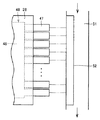
図1は、この発明の実施の形態における積層型電池を示す断面図である。図1を参照して、積層型電池10は、ガソリンエンジンやディーゼルエンジン等の内燃機関と、充放電可能な電源とを動力源とするハイブリッド自動車に電源として搭載される。積層型電池10は、リチウムイオン電池から形成されている。
FIG. 1 is a cross-sectional view showing a stacked battery according to an embodiment of the present invention. Referring to FIG. 1, stacked
積層型電池10は、矢印101に示す方向に積層された複数の単電池30と、複数の単電池30間に配設されたシート部材46とを備える。積層型電池10は、略直方体形状を有する。積層型電池10は、単電池30の積層方向の長さが他の辺の長さよりも小さい薄板形状を有しても良い。複数の単電池30は、電気的に直列に接続されている。積層型電池10は、たとえば、200V以上の電圧を有する。積層型電池10は、たとえば50以上の単電池30を備える。
The stacked
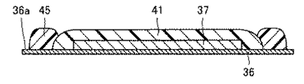
各単電池30は、シート状の正極集電箔31および負極集電箔36と、正極集電箔31および負極集電箔36にそれぞれ設けられた正極活物質層32および負極活物質層37と、正極活物質層32と負極活物質層37との間に設けられた電解質層41とを有する。本実施の形態における積層型電池10は、正極活物質層32および負極活物質層37が2枚の集電箔に別々に設けられる2次電池である。
Each unit cell 30 includes a sheet-like positive electrode
正極集電箔31および負極集電箔36は、表面31aおよび表面36aをそれぞれ有する。正極集電箔31および負極集電箔36は、表面31aと表面36aとが互いに距離を隔てて向い合うように、矢印101に示す単電池30の積層方向に重ね合わされている。
The positive electrode
複数の単電池30が有する正極集電箔31は、全て同一形状に形成されている。複数の単電池30が有する負極集電箔36は、全て同一形状に形成されている。正極集電箔31は、たとえばアルミニウムから形成されている。負極集電箔36は、たとえば銅から形成されている。
The positive electrode current collector foils 31 included in the plurality of single cells 30 are all formed in the same shape. The negative electrode current collector foils 36 included in the plurality of single cells 30 are all formed in the same shape. The positive electrode
正極活物質層32および負極活物質層37は、表面31aおよび表面36a上にそれぞれ形成されている。正極活物質層32と負極活物質層37とは、電解質層41を介して互いに対向する。電解質層41は、負極活物質層37を覆うように設けられている。電解質層41は、正極活物質層32を覆うように設けられても良いし、正極活物質層32および負極活物質層37の双方を覆うように設けられても良い。電解質層41は、正極活物質層32および負極活物質層37を必ずしも覆う必要はない。
The positive electrode
電解質層41は、イオン伝導性を示す材料から形成される層である。電解質層41を介在させることによって、正極活物質層32および負極活物質層37間のイオン伝導がスムーズになり、積層型電池10の出力を向上させることができる。本実施の形態では、電解質層41は、固体電解質から形成されている。電解質層41は、ゲル状の電解質であっても良いし、液体状の電解質であっても良い。この場合、電解質を含浸するセパレータによって電解質層41が構成される。
The
単電池30は、絶縁材料から形成された絶縁部材としての絶縁樹脂45をさらに有する。絶縁樹脂45は、正極集電箔31と負極集電箔36との間で表面31aおよび36aの周縁に沿って設けられている。絶縁樹脂45は、正極活物質層32、負極活物質層37および電解質層41の周囲を取り囲むように設けられている。正極活物質層32、負極活物質層37および電解質層41は、絶縁樹脂45によって、正極集電箔31と負極集電箔36との間の空間に封入されている。絶縁樹脂45は、絶縁材料から形成されており、たとえばエポキシ樹脂、アクリル樹脂、シリコーンゴムもしくはフッ素ゴムから形成されている。
The unit cell 30 further includes an insulating
複数の単電池30は、互いに隣り合う単電池30間で、正極集電箔31と負極集電箔36とが隣接するように積層されている。単電池30の積層方向の一方端に配置された正極集電箔31には、正極端子26が接続されている。単電池30の積層方向の他方端に配置された負極集電箔36には、負極端子27が接続されている。
The plurality of single cells 30 are stacked such that the positive electrode
積層された複数の単電池30は、外装体としてのラミネートフィルム28によって覆われている。ラミネートフィルム28としては、たとえば、アルミニウムからなる基材にポリエチレンテレフタラート樹脂(PET:poly ethylene terephthalate)が被膜されたものが使用される。ラミネートフィルム28は、主に水分の浸入を防止するために設けられている。電解質層41の種類等によっては、ラミネートフィルム28が省略されることもある。
The plurality of unit cells 30 stacked are covered with a
積層された複数の単電池30の両側には、拘束板21および23が配設されている。拘束板21と拘束板23とは、単電池30の積層方向に延びるボルト24によって互いに結合されている。ボルト24の軸力によって、複数の単電池30はその積層方向に拘束されている。なお、本実施の形態では、複数の単電池30を拘束する拘束部材として、ボルト24を用いたが、これに限定されず、たとえば単電池30の積層方向に締め付け力を発生させるゴムや紐、バンド、テープ等であっても良い。
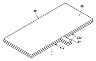
図2は、図1中の積層型電池が備えるシート部材を示す斜視図である。図1および図2を参照して、シート部材46は、互いに隣り合う複数の単電池30間で、正極集電箔31と負極集電箔36とに挟持されている。シート部材46は、正極集電箔31および負極集電箔36に接触する。シート部材46は、単電池30の積層方向にずれた複数箇所にそれぞれ設けられている。シート部材46は、互いに隣り合う単電池30間の全ての位置に配設されても良いし、その一部に配設されても良い。
FIG. 2 is a perspective view showing a sheet member provided in the stacked battery in FIG. 1. Referring to FIGS. 1 and 2,
シート部材46は、正極集電箔31と負極集電箔36との間に位置決めされる基部48と、正極集電箔31と負極集電箔36との間から延出する冷却用タブ47とを有する。基部48と冷却用タブ47とは、一体に成形されている。
The
本実施の形態では、基部48は、正極集電箔31および負極集電箔36の形状に対応して、略矩形形状を有する。冷却用タブ47は、基部48の端辺から突出するように形成されている。正極集電箔31と負極集電箔36との間から延出する冷却用タブ47は、ラミネートフィルム28の外側に引き出されている。
In the present embodiment, the
シート部材46は、熱伝導性に優れた材料から形成されている。シート部材46は、導電性材料から形成されている。シート部材46は、たとえば、アルミニウム、銅もしくはカーボンシートから形成されている。シート部材46は、正極集電箔31もしくは負極集電箔36と同じ材料から形成されても良い。シート部材46の厚みは、正極集電箔31および負極集電箔36の厚みよりも大きくても良い。シート部材46の厚みは、シート部材46を形成する材料の熱伝導性等を考慮して決定される。
The
図3は、図1中の矢印IIIに示す方向から見た積層型電池を示す平面図である。図1から図3を参照して、積層型電池10は、冷却風が流通する冷却風通路51をさらに備える。冷却風通路51は、電動ファン等を用いて冷却風が強制的に供給される通路であっても良いし、車両走行時、車両内に取り込まれた走行風が流通する通路であっても良い。冷却風通路51には、冷却器としてのフィン52が配設されている。ラミネートフィルム28から引き出された冷却用タブ47は、フィン52に接続されている。フィン52を設けず、冷却用タブ47の先端を直接、冷却風通路51内に配置しても良い。フィン52が曝される空気は、必ずしも対流していなくても良い。
FIG. 3 is a plan view showing the stacked battery as seen from the direction indicated by arrow III in FIG. With reference to FIGS. 1 to 3, the stacked
このような構成により、単電池30で発生した熱は、シート部材46の基部48および冷却用タブ47と順に伝わり、冷却風通路51に流通する冷却風と冷却用タブ47との間で熱交換が行なわれる。この際、本実施の形態では、基部48と冷却用タブ47とが一体に成形されているため、シート部材46を介した熱伝導が促進される。単電池30で発生した熱は、冷却風通路51に流通する冷却風に積極的に放熱され、積層型電池10の冷却効率が向上する。
With such a configuration, heat generated in the unit cell 30 is sequentially transmitted to the
各シート部材46の冷却用タブ47は、単電池30の積層方向において互いに重ならないように設けられている。複数のシート部材46のうち、単電池30の積層方向において相対的に内側に配設されたものをシート部材46mと呼び、相対的に外側に配設されたものをシート部材46nと呼ぶ。すなわち、単電池30の積層方向において、シート部材46mは、複数の単電池30の外殻から相対的に遠い位置に配置され、シート部材46nは、複数の単電池30の外殻から相対的に近い位置に配置されている。このとき、シート部材46mの冷却用タブ47は、シート部材46nの冷却用タブ47よりも、冷却風通路51内の冷却風流れの上流側でフィン52に接続されている。好ましくは、各シート部材46の冷却用タブ47は、単電池30の積層方向の外側から内側に移るに従って、冷却風通路51内の冷却風流れの下流側から上流側に徐々にずれるように設けられている。
The
このような構成により、シート部材46mの冷却用タブ47は、相対的に小さい温度を有する冷却風と熱交換を行ない、シート部材46nの冷却用タブ47は、シート部材46mの冷却用タブ47と熱交換を行なった後の相対的に大きい温度を有する冷却風と熱交換を行なうことになる。結果、冷却風とシート部材46mの冷却用タブ47との間の熱伝達率が、冷却風とシート部材46nの冷却用タブ47との間の熱伝達率よりも大きくなる。
With such a configuration, the
シート部材46mに接触する単電池30は、積層型電池10の外殻から遠い位置に配置されているため、熱がこもり易く、冷却効率が低い。これに対して、シート部材46nに接触する単電池30は、積層型電池10の外殻から近い位置に配置されているため、熱が逃げ易く、冷却効率が高い。このため、図2中のシート部材46の構成によれば、シート部材46mの冷却用タブ47を通じて、冷却効率の低い単電池30をより積極的に冷却することができる。これにより、複数の単電池30間で温度差が生じることを抑制し、単電池30の電池性能を十分に発揮させるとともに、単電池30の電池寿命を向上させることができる。
Since the unit cell 30 that contacts the
冷却用タブ47には、温度検出部としての温度センサや電圧検出部としての電圧センサが接続されても良い。このような構成により、センサが設けられた位置に対応する単電池30の内部温度や電圧を検出し、その検出値を積層型電池10の放充電電流の制御や冷却風を供給する電動ファンの制御等に利用することができる。
The
図4は、カーボンシートから形成されたシート部材を示す斜視図である。図4を参照して、図中のシート部材46は、熱伝導性に関して異方性を有するカーボンシートから形成されている。このカーボンシートは、シート部材46の面方向(矢印201に示す方向)において相対的に大きい熱伝導率を有し、シート部材46の厚み方向(矢印202に示す方向)において相対的に小さい熱伝導率を有する。このような特性を備えるカーボンシートを用いることにより、単電池30からシート部材46に伝わった熱が、さらに基部48から冷却用タブ47へと迅速に伝わるため、積層型電池10の冷却効率をより効果的に向上させることができる。
FIG. 4 is a perspective view showing a sheet member formed from a carbon sheet. Referring to FIG. 4, the
続いて、図1中の積層型電池10を構成する各部材について詳細な説明を行なう。正極活物質層32は、正極活物質および固体高分子電解質を含む。正極活物質層32は、イオン伝導性を高めるための支持塩(リチウム塩)、電子伝導性を高めるための導電助剤、スラリー粘度の調整溶媒としてのNMP(N−メチル−2−ピロリドン)、重合開始剤としてのAIBN(アゾビスイソブチロニトリル)等を含んでも良い。
Subsequently, each member constituting the stacked
正極活物質としては、リチウムイオン2次電池で一般的に用いられる、リチウムと遷移金属との複合酸化物を使用することができる。正極活物質として、たとえば、LiCoO2等のLi・Co系複合酸化物、LiNiO2等のLi・Ni系複合酸化物、スピネルLiMn2O4等のLi・Mn系複合酸化物、LiFeO2等のLi・Fe系複合酸化物などが挙げられる。その他、LiFePO4等の遷移金属とリチウムとのリン酸化合物や硫酸化合物;V2O5、MnO2、TiS2、MoS2、MoO3等の遷移金属酸化物や硫化物;PbO2、AgO、NiOOH等が挙げられる。 As the positive electrode active material, a composite oxide of lithium and a transition metal, which is generally used in a lithium ion secondary battery, can be used. As the positive electrode active material, for example, Li · Co-based composite oxide such as LiCoO 2, Li · Ni-based composite oxide such as LiNiO 2, Li · Mn-based composite oxide such as spinel LiMn 2 O 4, such as LiFeO 2 Examples include Li · Fe-based composite oxides. In addition, phosphoric acid compounds and sulfuric acid compounds of transition metals such as LiFePO 4 and lithium; transition metal oxides and sulfides such as V 2 O 5 , MnO 2 , TiS 2 , MoS 2 , MoO 3 ; PbO 2 , AgO, NiOOH etc. are mentioned.
固体高分子電解質は、イオン伝導性を示す高分子であれば、特に限定されず、たとえば、ポリエチレンオキシド(PEO)、ポリプロピレンオキシド(PPO)、これらの共重合体などが挙げられる。このようなポリアルキレンオキシド系高分子は、LiBF4、LiPF6、LiN(SO2CF3)2、LiN(SO2C2F5)2等のリチウム塩を容易に溶解する。固体高分子電解質は、正極活物質層32および負極活物質層37の少なくとも一方に含まれる。より好ましくは、固体高分子電解質は、正極活物質層32および負極活物質層37の双方に含まれる。
The solid polymer electrolyte is not particularly limited as long as it is a polymer exhibiting ion conductivity, and examples thereof include polyethylene oxide (PEO), polypropylene oxide (PPO), and copolymers thereof. Such a polyalkylene oxide polymer readily dissolves lithium salts such as LiBF 4 , LiPF 6 , LiN (SO 2 CF 3 ) 2 , and LiN (SO 2 C 2 F 5 ) 2 . The solid polymer electrolyte is contained in at least one of the positive electrode
支持塩としては、Li(C2F5SO2)2N、LiBF4、LiPF6、LiN(SO2C2F5)2、もしくはこれらの混合物等を使用することができる。導電助剤としては、アセチレンブラック、カーボンブラック、グラファイト等を使用することができる。 As the supporting salt, Li (C 2 F 5 SO 2 ) 2 N, LiBF 4 , LiPF 6 , LiN (SO 2 C 2 F 5 ) 2 , or a mixture thereof can be used. As the conductive auxiliary agent, acetylene black, carbon black, graphite or the like can be used.
負極活物質層37は、負極活物質および固体高分子電解質を含む。負極活物質層は、イオン伝導性を高めるための支持塩(リチウム塩)、電子伝導性を高めるための導電助剤、スラリー粘度の調整溶媒としてのNMP(N−メチル−2−ピロリドン)、重合開始剤としてのAIBN(アゾビスイソブチロニトリル)等を含んでも良い。
The negative electrode
負極活物質としては、リチウムイオン2次電池で一般的に用いられる材料を使用することができる。但し、固体電解質を使用する場合、負極活物質として、カーボンもしくはリチウムと金属酸化物もしくは金属との複合酸化物を用いることが好ましい。より好ましくは、負極活物質は、カーボンもしくはリチウムと遷移金属との複合酸化物である。さらに好ましくは、遷移金属はチタンである。つまり、負極活物質は、チタン酸化物もしくはチタンとリチウムとの複合酸化物であることがさらに好ましい。 As a negative electrode active material, the material generally used with a lithium ion secondary battery can be used. However, when a solid electrolyte is used, it is preferable to use a composite oxide of carbon or lithium and a metal oxide or metal as the negative electrode active material. More preferably, the negative electrode active material is a composite oxide of carbon or lithium and a transition metal. More preferably, the transition metal is titanium. That is, the negative electrode active material is more preferably titanium oxide or a composite oxide of titanium and lithium.
電解質層41を形成する固体電解質としては、たとえば、ポリエチレンオキシド(PEO)、ポリプロピレンオキシド(PPO)、これらの共重合体等、固体高分子電解質を使用することができる。固体電解質は、イオン伝導性を確保するための支持塩(リチウム塩)を含む。支持塩としては、LiBF4、LiPF6、LiN(SO2CF3)2、LiN(SO2C2F5)2、もしくはこれらの混合物等を使用することができる。
As the solid electrolyte forming the
さらに、正極活物質層32、負極活物質層37および電解質層41を形成する材料の具体例を表1から表3に示す。表1は、電解質層41が有機系固体電解質である場合の具体例であり、表2は、電解質層41が無機系固体電解質である場合の具体例であり、表3は、電解質層41がゲル状電解質である場合の具体例である。
Further, specific examples of materials for forming the positive electrode

続いて、単電池30の製造方法について説明を行なう。図5から図10は、図1中の積層型電池が備える単電池の製造方法の工程を示す断面図である。図5を参照して、スパッタリング等の成膜工程により、正極集電箔31の表面31a上に正極活物質層32を形成する。図6を参照して、正極活物質層32の周囲を取り囲むように、表面31a上に絶縁樹脂45を塗布する。
Then, the manufacturing method of the cell 30 is demonstrated. 5 to 10 are cross-sectional views showing the steps of a method for manufacturing a unit cell included in the stacked battery in FIG. Referring to FIG. 5, positive electrode
図7を参照して、図5に示す工程と同様に、負極集電箔36の表面36a上に負極活物質層37を形成する。さらに、その負極活物質層37を覆うように表面36a上に電解質層41を形成する。図8を参照して、負極活物質層37および電解質層41の周囲を取り囲むように、表面36a上に絶縁樹脂45を塗布する。
Referring to FIG. 7, a negative electrode
図9を参照して、正極集電箔31と負極集電箔36とを互いに重ね合わせる。正極集電箔31および負極集電箔36にそれぞれ塗布した絶縁樹脂45を、互いに接触した状態で硬化させる。これにより、正極集電箔31と負極集電箔36とが一体化される。図10を参照して、絶縁樹脂45に切断面が形成されるように、正極集電箔31および負極集電箔36の周縁を切断する。以上の工程により、図1中の積層型電池10が備える単電池30が完成する。
Referring to FIG. 9, positive electrode
図11は、図5および図6中に示す工程を経て得られた正極集電箔を示す斜視図である。図11を参照して、図5および図6中に示す工程において、1枚の正極集電箔131上の間隔を隔てた複数箇所に、それぞれ正極活物質層32および絶縁樹脂45を形成しても良い。同様に、図7および図8中に示す工程において、1枚の負極集電箔上の間隔を隔てた複数箇所に、それぞれ負極活物質層37、電解質層41および絶縁樹脂45を形成しても良い。その後、図9および図10中にそれぞれ示す積層工程および切断工程を実施することによって、複数の単電池30を一括に作製することができる。
FIG. 11 is a perspective view showing a positive electrode current collector foil obtained through the steps shown in FIGS. 5 and 6. Referring to FIG. 11, in the steps shown in FIGS. 5 and 6, positive electrode
この発明の実施の形態における積層型電池10は、正極集電体としての正極集電箔31および負極集電体としての負極集電箔36を有し、積層された複数の単電池30と、互いに隣り合う複数の単電池30間に配置され、正極集電箔31と負極集電箔36とに挟持されるシート部材46とを備える。正極集電箔31および負極集電箔36には、正極活物質層32および負極活物質層37がそれぞれ設けられている。正極集電箔31および負極集電箔36は、正極活物質層32と負極活物質層37とが電解質としての電解質層41を介して対向するように重ね合わされている。シート部材46は、正極集電箔31と負極集電箔36との間から延出する延出部としての冷却用タブ47を有する。
A stacked
このように構成された、この発明の実施の形態における積層型電池10によれば、複数の単電池30間に配置されるシート部材46によって、積層型電池10の冷却効率を向上させることができる。この際、本実施の形態では、冷却用タブ47をシート部材46に設けているため、冷却用タブ47が引き出される位置に合わせて正極集電箔31および負極集電箔36をそれぞれ複数種類、準備する必要がない。これにより、積層型電池10の製造時の正極集電箔31および負極集電箔36の管理を容易にし、その製造コストを低く抑えることができる。また、図5から図10中に示す工程時に、冷却用タブ47が設けられた正極集電箔31および負極集電箔36を取り扱う必要がない。このため、正極集電箔31および負極集電箔36のハンドリングを容易に行なうことができ、生産効率や歩留まりを向上させることができる。また、成膜装置等の大型化を招くことを回避できる。加えて、本実施の形態では、シート部材46を配設する箇所を変更することにより、積層型電池10の冷却効率を適切に制御することが可能となる。
According to the stacked
なお、本実施の形態では、積層型電池10がリチウムイオン電池から形成されている場合について説明したが、これに限定されず、リチウムイオン電池以外の2次電池から形成されても良い。
In the present embodiment, the case where the stacked
また、積層型電池10を、燃料電池と2次電池とを駆動源とする燃料電池ハイブリッド車両(FCHV:Fuel Cell Hybrid Vehicle)または電気自動車(EV:Electric Vehicle)に搭載することもできる。本実施の形態におけるハイブリッド車両では、燃費最適動作点で内燃機関を駆動するのに対して、燃料電池ハイブリッド車両では、発電効率最適動作点で燃料電池を駆動する。また、2次電池の使用に関しては、両方のハイブリッド車両で基本的に変わらない。
In addition, the stacked
図12は、図1中の積層型電池が備えるシート部材の第1の変形例を示す断面図である。図12を参照して、本変形例では、単電池30の積層方向の内側に配設されるシート部材46mが、相対的に大きい厚みを有し、外側に配設されるシート部材46nが、相対的に小さい厚みを有する。好ましくは、各シート部材46は、単電池30の積層方向の外側から内側に移るに従って、徐々に大きい厚みを有するように形成されている。
FIG. 12 is a cross-sectional view illustrating a first modification of the sheet member provided in the stacked battery in FIG. 1. Referring to FIG. 12, in this modification, the
このようにシート部材46の厚みTを調整することによっても、冷却風とシート部材46mの冷却用タブ47との間の熱伝達率が、冷却風とシート部材46nの冷却用タブ47との間の熱伝達率よりも大きくなる構成が得られる。これにより、複数の単電池30間で温度差が生じることを抑制できる。
By adjusting the thickness T of the
図13は、図1中の積層型電池が備えるシート部材の第2の変形例を示す斜視図である。図14は、図13中のXIV−XIV線上に沿ったシート部材の断面図である。図13および図14を参照して、本変形例では、複数のシート部材46が、全て同一形状を有する。冷却用タブ47は、単電池30の積層方向において、互いに重なり合うように設けられている。冷却用タブ47は、絶縁材料から形成された被覆部49によって覆われている。
FIG. 13 is a perspective view showing a second modification of the sheet member provided in the stacked battery in FIG. 1. 14 is a cross-sectional view of the sheet member taken along line XIV-XIV in FIG. Referring to FIGS. 13 and 14, in the present modification, the plurality of
このような構成により、シート部材46の種類が1種類となるため、その製造コストを削減することができる。加えて、被覆部49を設けることにより複数の単電池30間が短絡することを防止できる。
With such a configuration, since the type of the
今回開示された実施の形態はすべての点で例示であって制限的なものではないと考えられるべきである。本発明の範囲は上記した説明ではなくて特許請求の範囲によって示され、特許請求の範囲と均等の意味および範囲内でのすべての変更が含まれることが意図される。 The embodiment disclosed this time should be considered as illustrative in all points and not restrictive. The scope of the present invention is defined by the terms of the claims, rather than the description above, and is intended to include any modifications within the scope and meaning equivalent to the terms of the claims.
10 積層型電池、30 単電池、31 正極集電箔、32 正極活物質層、36 負極集電箔、37 負極活物質層、41 電解質層、46,46m,46n シート部材、47 冷却用タブ、49 被覆部、51 冷却風通路。
DESCRIPTION OF
Claims (3)
互いに隣り合う前記複数の単電池間に配置され、前記正極集電体と前記負極集電体とに挟持されるシート部材とを備え、
前記シート部材は、前記正極集電体と前記負極集電体との間に位置決めされる基部と、前記正極集電体と前記負極集電体との間から延出する延出部とを有し、
前記延出部は、前記基部の端辺の一部の範囲から突出するタブ形状を有し、
前記延出部が接続され、冷媒が流通する冷媒通路をさらに備え、
前記シート部材は、前記複数の単電池の積層方向にずれた複数箇所にそれぞれ配設され、
複数の前記シート部材は、前記複数の単電池の積層方向において相対的に内側に配置される第1のシート部材と、相対的に外側に配置される第2のシート部材とを含み、
前記延出部は、前記第1のシート部材が有する前記延出部と冷媒との間の熱伝達率が相対的に大きくなり、前記第2のシート部材が有する前記延出部と冷媒との間の熱伝達率が相対的に小さくなるように設けられ、
前記第1のシート部材が有する前記延出部は、前記第2のシート部材が有する前記延出部よりも前記冷媒通路内の冷媒流れの上流側に接続される、積層型電池。 A positive electrode active material layer and a negative electrode active material layer are provided, respectively, and the positive electrode active material layer and the negative electrode active material layer are stacked so that the positive electrode active material layer and the negative electrode active material layer face each other through an electrolyte. A plurality of stacked unit cells;
A sheet member disposed between the plurality of unit cells adjacent to each other and sandwiched between the positive electrode current collector and the negative electrode current collector;
The sheet member is used, the number of said base portion being positioned between the positive electrode current collector wherein the negative electrode current collector, said extending portion extending from between the positive electrode current collector The anode current collector And
The extending portion has a tab shape protruding from a partial range of the end side of the base portion,
The extension portion is connected, further comprising a refrigerant passage through which the refrigerant flows,
The sheet members are respectively disposed at a plurality of locations shifted in the stacking direction of the plurality of unit cells,
The plurality of sheet members include a first sheet member disposed relatively inside in the stacking direction of the plurality of single cells, and a second sheet member disposed relatively outside.
The extension part has a relatively large heat transfer coefficient between the extension part of the first sheet member and the refrigerant, and the extension part of the second sheet member and the refrigerant Between the heat transfer coefficient is relatively small,
The extension part which the 1st sheet member has is a lamination type battery connected to the upstream of the refrigerant flow in the refrigerant passage rather than the extension part which the 2nd sheet member has .
Priority Applications (5)
| Application Number | Priority Date | Filing Date | Title |
|---|---|---|---|
| JP2006099090A JP4923679B2 (en) | 2006-03-31 | 2006-03-31 | Stacked battery |
| PCT/JP2007/057017 WO2007114310A1 (en) | 2006-03-31 | 2007-03-23 | Stacked cell |
| EP20070740455 EP2003722B1 (en) | 2006-03-31 | 2007-03-23 | Stacked cell |
| CNA2007800120618A CN101416343A (en) | 2006-03-31 | 2007-03-23 | Stacked type battery |
| US12/087,452 US20090035648A1 (en) | 2006-03-31 | 2007-03-23 | Stacked Type Battery |
Applications Claiming Priority (1)
| Application Number | Priority Date | Filing Date | Title |
|---|---|---|---|
| JP2006099090A JP4923679B2 (en) | 2006-03-31 | 2006-03-31 | Stacked battery |
Publications (2)
| Publication Number | Publication Date |
|---|---|
| JP2007273348A JP2007273348A (en) | 2007-10-18 |
| JP4923679B2 true JP4923679B2 (en) | 2012-04-25 |
Family
ID=38563577
Family Applications (1)
| Application Number | Title | Priority Date | Filing Date |
|---|---|---|---|
| JP2006099090A Expired - Fee Related JP4923679B2 (en) | 2006-03-31 | 2006-03-31 | Stacked battery |
Country Status (5)
| Country | Link |
|---|---|
| US (1) | US20090035648A1 (en) |
| EP (1) | EP2003722B1 (en) |
| JP (1) | JP4923679B2 (en) |
| CN (1) | CN101416343A (en) |
| WO (1) | WO2007114310A1 (en) |
Cited By (1)
| Publication number | Priority date | Publication date | Assignee | Title |
|---|---|---|---|---|
| US9865904B2 (en) | 2012-06-12 | 2018-01-09 | Lg Chem, Ltd. | Battery cell of improved cooling efficiency |
Families Citing this family (116)
| Publication number | Priority date | Publication date | Assignee | Title |
|---|---|---|---|---|
| JP5061502B2 (en) * | 2006-05-20 | 2012-10-31 | 日産自動車株式会社 | Battery structure |
| KR100998846B1 (en) * | 2007-11-21 | 2010-12-08 | 주식회사 엘지화학 | Battery Cell of Excellent Heat Dissipation Property and Middle or Large-sized Battery Module Employed with the Same |
| JP5159425B2 (en) * | 2008-05-19 | 2013-03-06 | 古河電池株式会社 | Battery module |
| EP2251922A1 (en) * | 2008-07-25 | 2010-11-17 | Panasonic Corporation | Bipolar cell |
| DE102009005854A1 (en) * | 2009-01-23 | 2010-07-29 | Li-Tec Battery Gmbh | Battery cell with enclosure |
| JP5392951B2 (en) * | 2009-06-18 | 2014-01-22 | 古河電池株式会社 | Secondary battery |
| JP2011065982A (en) * | 2009-08-18 | 2011-03-31 | Seiko Epson Corp | Lithium battery electrode body and lithium battery |
| US8623537B2 (en) * | 2009-08-18 | 2014-01-07 | Samsung Sdi Co., Ltd. | Rechargeable battery and battery module |
| DE102009051213A1 (en) * | 2009-10-29 | 2011-05-12 | Li-Tec Battery Gmbh | Electrochemical cell |
| KR101093890B1 (en) * | 2010-01-12 | 2011-12-13 | 삼성에스디아이 주식회사 | Secondary Battery |
| WO2012019062A2 (en) * | 2010-08-04 | 2012-02-09 | Front Edge Technology, Inc. | Rechargeable battery with current limiter |
| DE102010062858B4 (en) | 2010-12-10 | 2023-06-01 | Robert Bosch Gmbh | battery cell |
| US8828576B2 (en) | 2011-03-11 | 2014-09-09 | GM Global Technology Operations LLC | Prismatic cell with integrated cooling plate |
| JP6020920B2 (en) * | 2013-04-09 | 2016-11-02 | 株式会社デンソー | Electricity storage element |
| JP6499043B2 (en) * | 2015-08-21 | 2019-04-10 | 太陽誘電株式会社 | Electrochemical devices |
| US10439260B2 (en) * | 2016-06-30 | 2019-10-08 | Toyota Jidosha Kabushiki Kaisha | Battery |
| JP6534975B2 (en) * | 2016-08-16 | 2019-06-26 | トヨタ自動車株式会社 | Bipolar battery |
| GB2555649B (en) * | 2016-11-08 | 2021-03-10 | Oxis Energy Ltd | Battery |
| EP3413393A1 (en) * | 2017-06-07 | 2018-12-12 | Robert Bosch GmbH | Electrode assembly for a battery module |
| CN109860859A (en) * | 2017-06-28 | 2019-06-07 | 湖南妙盛汽车电源有限公司 | A kind of lithium-ion-power cell |
| CN109860941A (en) * | 2017-06-28 | 2019-06-07 | 湖南妙盛汽车电源有限公司 | A kind of lithium-ion-power cell |
| CN110112494A (en) * | 2017-06-28 | 2019-08-09 | 湖南妙盛汽车电源有限公司 | A kind of lithium-ion-power cell |
| CN110148809A (en) * | 2017-06-28 | 2019-08-20 | 湖南妙盛汽车电源有限公司 | A kind of lithium-ion-power cell |
| CN109860818A (en) * | 2017-06-28 | 2019-06-07 | 湖南妙盛汽车电源有限公司 | A kind of lithium-ion-power cell |
| CN109935935A (en) * | 2017-06-28 | 2019-06-25 | 湖南妙盛汽车电源有限公司 | A kind of lithium-ion-power cell |
| CN109860938A (en) * | 2017-06-28 | 2019-06-07 | 湖南妙盛汽车电源有限公司 | A kind of lithium-ion-power cell |
| CN109860840A (en) * | 2017-06-28 | 2019-06-07 | 湖南妙盛汽车电源有限公司 | A kind of lithium-ion-power cell |
| CN110120563A (en) * | 2017-06-28 | 2019-08-13 | 湖南妙盛汽车电源有限公司 | A kind of lithium-ion-power cell |
| CN109860832A (en) * | 2017-06-28 | 2019-06-07 | 湖南妙盛汽车电源有限公司 | A kind of lithium-ion-power cell |
| CN109860935A (en) * | 2017-06-28 | 2019-06-07 | 湖南妙盛汽车电源有限公司 | A kind of lithium-ion-power cell |
| CN109860914A (en) * | 2017-06-28 | 2019-06-07 | 湖南妙盛汽车电源有限公司 | A kind of lithium-ion-power cell |
| CN109860931A (en) * | 2017-06-28 | 2019-06-07 | 湖南妙盛汽车电源有限公司 | A kind of lithium-ion-power cell |
| CN109860827A (en) * | 2017-06-28 | 2019-06-07 | 湖南妙盛汽车电源有限公司 | A kind of lithium-ion-power cell |
| CN109860861A (en) * | 2017-06-28 | 2019-06-07 | 湖南妙盛汽车电源有限公司 | A kind of lithium-ion-power cell |
| CN110137594A (en) * | 2017-06-28 | 2019-08-16 | 湖南妙盛汽车电源有限公司 | A kind of lithium-ion-power cell |
| CN109860794A (en) * | 2017-06-28 | 2019-06-07 | 湖南妙盛汽车电源有限公司 | A kind of lithium-ion-power cell |
| CN109860772A (en) * | 2017-06-28 | 2019-06-07 | 湖南妙盛汽车电源有限公司 | A kind of lithium-ion-power cell |
| CN109873221A (en) * | 2017-06-28 | 2019-06-11 | 湖南妙盛汽车电源有限公司 | A kind of lithium-ion-power cell |
| CN109860833A (en) * | 2017-06-28 | 2019-06-07 | 湖南妙盛汽车电源有限公司 | A kind of lithium-ion-power cell |
| CN109860871A (en) * | 2017-06-28 | 2019-06-07 | 湖南妙盛汽车电源有限公司 | A kind of lithium-ion-power cell |
| CN109860770A (en) * | 2017-06-28 | 2019-06-07 | 湖南妙盛汽车电源有限公司 | A kind of lithium-ion-power cell |
| CN109860936A (en) * | 2017-06-28 | 2019-06-07 | 湖南妙盛汽车电源有限公司 | A kind of lithium-ion-power cell |
| CN109921140A (en) * | 2017-06-28 | 2019-06-21 | 湖南妙盛汽车电源有限公司 | A kind of lithium-ion-power cell |
| CN109860767A (en) * | 2017-06-28 | 2019-06-07 | 湖南妙盛汽车电源有限公司 | A kind of lithium-ion-power cell |
| CN109860860A (en) * | 2017-06-28 | 2019-06-07 | 湖南妙盛汽车电源有限公司 | A kind of lithium-ion-power cell |
| CN109904553A (en) * | 2017-06-28 | 2019-06-18 | 湖南妙盛汽车电源有限公司 | A kind of lithium-ion-power cell |
| CN109860939A (en) * | 2017-06-28 | 2019-06-07 | 湖南妙盛汽车电源有限公司 | A kind of lithium-ion-power cell |
| CN110137596A (en) * | 2017-06-28 | 2019-08-16 | 湖南妙盛汽车电源有限公司 | A kind of lithium-ion-power cell |
| CN109873236A (en) * | 2017-06-28 | 2019-06-11 | 湖南妙盛汽车电源有限公司 | A kind of lithium-ion-power cell |
| CN110120562A (en) * | 2017-06-28 | 2019-08-13 | 湖南妙盛汽车电源有限公司 | A kind of lithium-ion-power cell |
| CN109860764A (en) * | 2017-06-28 | 2019-06-07 | 湖南妙盛汽车电源有限公司 | A kind of lithium-ion-power cell |
| CN109873215A (en) * | 2017-06-28 | 2019-06-11 | 湖南妙盛汽车电源有限公司 | A kind of lithium-ion-power cell |
| CN110112497A (en) * | 2017-06-28 | 2019-08-09 | 湖南妙盛汽车电源有限公司 | A kind of lithium-ion-power cell |
| CN109873230A (en) * | 2017-06-28 | 2019-06-11 | 湖南妙盛汽车电源有限公司 | A kind of lithium-ion-power cell |
| CN109935925A (en) * | 2017-06-28 | 2019-06-25 | 湖南妙盛汽车电源有限公司 | A kind of lithium-ion-power cell |
| CN109935930A (en) * | 2017-06-28 | 2019-06-25 | 湖南妙盛汽车电源有限公司 | A kind of lithium-ion-power cell |
| CN109860905A (en) * | 2017-06-28 | 2019-06-07 | 湖南妙盛汽车电源有限公司 | A kind of lithium-ion-power cell |
| CN109860782A (en) * | 2017-06-28 | 2019-06-07 | 湖南妙盛汽车电源有限公司 | A kind of lithium-ion-power cell |
| CN109935929A (en) * | 2017-06-28 | 2019-06-25 | 湖南妙盛汽车电源有限公司 | A kind of lithium-ion-power cell |
| CN109860756A (en) * | 2017-06-28 | 2019-06-07 | 湖南妙盛汽车电源有限公司 | A kind of lithium-ion-power cell |
| CN109860811A (en) * | 2017-06-28 | 2019-06-07 | 湖南妙盛汽车电源有限公司 | A kind of lithium-ion-power cell |
| CN109860784A (en) * | 2017-06-28 | 2019-06-07 | 湖南妙盛汽车电源有限公司 | A kind of lithium-ion-power cell |
| CN109860769A (en) * | 2017-06-28 | 2019-06-07 | 湖南妙盛汽车电源有限公司 | A kind of lithium-ion-power cell |
| CN109873225A (en) * | 2017-06-28 | 2019-06-11 | 湖南妙盛汽车电源有限公司 | A kind of lithium-ion-power cell |
| CN109921129A (en) * | 2017-06-28 | 2019-06-21 | 湖南妙盛汽车电源有限公司 | A kind of lithium-ion-power cell |
| CN110120561A (en) * | 2017-06-28 | 2019-08-13 | 湖南妙盛汽车电源有限公司 | A kind of lithium-ion-power cell |
| CN109873235A (en) * | 2017-06-28 | 2019-06-11 | 湖南妙盛汽车电源有限公司 | A kind of lithium-ion-power cell |
| CN109860761A (en) * | 2017-06-28 | 2019-06-07 | 湖南妙盛汽车电源有限公司 | A kind of lithium-ion-power cell |
| CN110112498A (en) * | 2017-06-28 | 2019-08-09 | 湖南妙盛汽车电源有限公司 | A kind of lithium-ion-power cell |
| CN109860879A (en) * | 2017-06-28 | 2019-06-07 | 湖南妙盛汽车电源有限公司 | A kind of lithium-ion-power cell |
| CN109860778A (en) * | 2017-06-28 | 2019-06-07 | 湖南妙盛汽车电源有限公司 | A kind of lithium-ion-power cell |
| CN109860855A (en) * | 2017-06-28 | 2019-06-07 | 湖南妙盛汽车电源有限公司 | A kind of lithium-ion-power cell |
| CN109860848A (en) * | 2017-06-28 | 2019-06-07 | 湖南妙盛汽车电源有限公司 | A kind of lithium-ion-power cell |
| CN109860885A (en) * | 2017-06-28 | 2019-06-07 | 湖南妙盛汽车电源有限公司 | A kind of lithium-ion-power cell |
| CN109860754A (en) * | 2017-06-28 | 2019-06-07 | 湖南妙盛汽车电源有限公司 | A kind of lithium-ion-power cell |
| CN110137614A (en) * | 2017-06-28 | 2019-08-16 | 湖南妙盛汽车电源有限公司 | A kind of lithium-ion-power cell |
| CN109860823A (en) * | 2017-06-28 | 2019-06-07 | 湖南妙盛汽车电源有限公司 | A kind of lithium-ion-power cell |
| CN109860779A (en) * | 2017-06-28 | 2019-06-07 | 湖南妙盛汽车电源有限公司 | A kind of lithium-ion-power cell |
| CN109860766A (en) * | 2017-06-28 | 2019-06-07 | 湖南妙盛汽车电源有限公司 | A kind of lithium-ion-power cell |
| CN109860845A (en) * | 2017-06-28 | 2019-06-07 | 湖南妙盛汽车电源有限公司 | A kind of lithium-ion-power cell |
| CN109873226A (en) * | 2017-06-28 | 2019-06-11 | 湖南妙盛汽车电源有限公司 | A kind of lithium-ion-power cell |
| CN109860807A (en) * | 2017-06-28 | 2019-06-07 | 湖南妙盛汽车电源有限公司 | A kind of lithium-ion-power cell |
| CN109860866A (en) * | 2017-06-28 | 2019-06-07 | 湖南妙盛汽车电源有限公司 | A kind of lithium-ion-power cell |
| CN109860864A (en) * | 2017-06-28 | 2019-06-07 | 湖南妙盛汽车电源有限公司 | A kind of lithium-ion-power cell |
| CN109860768A (en) * | 2017-06-28 | 2019-06-07 | 湖南妙盛汽车电源有限公司 | A kind of lithium-ion-power cell |
| CN109860903A (en) * | 2017-06-28 | 2019-06-07 | 湖南妙盛汽车电源有限公司 | A kind of lithium-ion-power cell |
| CN109860817A (en) * | 2017-06-28 | 2019-06-07 | 湖南妙盛汽车电源有限公司 | A kind of lithium-ion-power cell |
| CN109904554A (en) * | 2017-06-28 | 2019-06-18 | 湖南妙盛汽车电源有限公司 | A kind of lithium-ion-power cell |
| CN109860856A (en) * | 2017-06-28 | 2019-06-07 | 湖南妙盛汽车电源有限公司 | A kind of lithium-ion-power cell |
| CN109873227A (en) * | 2017-06-28 | 2019-06-11 | 湖南妙盛汽车电源有限公司 | A kind of lithium-ion-power cell |
| CN109935933A (en) * | 2017-06-28 | 2019-06-25 | 湖南妙盛汽车电源有限公司 | A kind of lithium-ion-power cell |
| CN109860891A (en) * | 2017-06-28 | 2019-06-07 | 湖南妙盛汽车电源有限公司 | A kind of lithium-ion-power cell |
| CN109860862A (en) * | 2017-06-28 | 2019-06-07 | 湖南妙盛汽车电源有限公司 | A kind of lithium-ion-power cell |
| CN109888428A (en) * | 2017-06-28 | 2019-06-14 | 湖南妙盛汽车电源有限公司 | A kind of lithium-ion-power cell |
| CN109860812A (en) * | 2017-06-28 | 2019-06-07 | 湖南妙盛汽车电源有限公司 | A kind of lithium-ion-power cell |
| CN109888426A (en) * | 2017-06-28 | 2019-06-14 | 湖南妙盛汽车电源有限公司 | A kind of lithium-ion-power cell |
| CN109904551A (en) * | 2017-06-28 | 2019-06-18 | 湖南妙盛汽车电源有限公司 | A kind of lithium-ion-power cell |
| CN109860755A (en) * | 2017-06-28 | 2019-06-07 | 湖南妙盛汽车电源有限公司 | A kind of lithium-ion-power cell |
| CN109873224A (en) * | 2017-06-28 | 2019-06-11 | 湖南妙盛汽车电源有限公司 | A kind of lithium-ion-power cell |
| CN109860763A (en) * | 2017-06-28 | 2019-06-07 | 湖南妙盛汽车电源有限公司 | A kind of lithium-ion-power cell |
| CN109860872A (en) * | 2017-06-28 | 2019-06-07 | 湖南妙盛汽车电源有限公司 | A kind of lithium-ion-power cell |
| CN109921134A (en) * | 2017-06-28 | 2019-06-21 | 湖南妙盛汽车电源有限公司 | A kind of lithium-ion-power cell |
| CN109873238A (en) * | 2017-06-28 | 2019-06-11 | 湖南妙盛汽车电源有限公司 | A kind of lithium-ion-power cell |
| CN109860805A (en) * | 2017-06-28 | 2019-06-07 | 湖南妙盛汽车电源有限公司 | A kind of lithium-ion-power cell |
| CN109860759A (en) * | 2017-06-28 | 2019-06-07 | 湖南妙盛汽车电源有限公司 | A kind of lithium-ion-power cell |
| CN110137603A (en) * | 2017-06-28 | 2019-08-16 | 湖南妙盛汽车电源有限公司 | A kind of lithium-ion-power cell |
| CN109860895A (en) * | 2017-06-28 | 2019-06-07 | 湖南妙盛汽车电源有限公司 | A kind of lithium-ion-power cell |
| JP6982460B2 (en) * | 2017-10-16 | 2021-12-17 | 三洋化成工業株式会社 | Lithium ion battery |
| JP7059828B2 (en) * | 2017-11-30 | 2022-04-26 | 三菱ケミカル株式会社 | Heat transfer control method for partition members, assembled batteries and assembled batteries |
| CN209401683U (en) * | 2018-12-29 | 2019-09-17 | 宁德时代新能源科技股份有限公司 | Secondary cell and battery modules |
| KR102429590B1 (en) * | 2019-04-22 | 2022-08-05 | 주식회사 엘지에너지솔루션 | Electrode assembly |
| JP7215433B2 (en) * | 2020-01-15 | 2023-01-31 | トヨタ自動車株式会社 | battery |
| JP7264077B2 (en) * | 2020-01-31 | 2023-04-25 | トヨタ自動車株式会社 | All-solid battery |
| JP7196872B2 (en) * | 2020-02-26 | 2022-12-27 | トヨタ自動車株式会社 | Bipolar batteries and bipolar battery stacks |
| JP7399750B2 (en) | 2020-03-03 | 2023-12-18 | 本田技研工業株式会社 | Quick charging device and quick charging method |
| EP4033571A1 (en) * | 2021-01-22 | 2022-07-27 | Geyser Batteries Oy | Assembly of elements and electrochemical energy storage device |
Family Cites Families (15)
| Publication number | Priority date | Publication date | Assignee | Title |
|---|---|---|---|---|
| JPH05159808A (en) * | 1991-12-06 | 1993-06-25 | Yuasa Corp | Layered thin-type battery |
| JPH06215794A (en) * | 1993-01-18 | 1994-08-05 | Shin Kobe Electric Mach Co Ltd | Thin type sealed storage battery |
| JP3271495B2 (en) * | 1995-10-24 | 2002-04-02 | 松下電器産業株式会社 | Battery pack |
| US6632538B1 (en) * | 1998-02-05 | 2003-10-14 | Dai Nippon Printing Co., Ltd. | Sheet for cell and cell device |
| JP3727840B2 (en) * | 2000-09-29 | 2005-12-21 | 株式会社東芝 | Battery pack and portable electronic device |
| US6806679B2 (en) * | 2001-06-20 | 2004-10-19 | Tai-Her Yang | Low internal impedance current pool for a charging/discharging device |
| JP4361229B2 (en) * | 2001-07-04 | 2009-11-11 | 日産自動車株式会社 | Battery system |
| JP4114415B2 (en) | 2002-06-28 | 2008-07-09 | 日産自動車株式会社 | Electrode laminated battery cooling device |
| JP2004087238A (en) | 2002-08-26 | 2004-03-18 | Nissan Motor Co Ltd | Layer built cell |
| US20050074666A1 (en) * | 2002-08-29 | 2005-04-07 | Hirokazu Kimiya | Heat control device for battery |
| JP4155054B2 (en) * | 2003-02-18 | 2008-09-24 | 日産自動車株式会社 | Bipolar battery |
| JP4111043B2 (en) | 2003-04-18 | 2008-07-02 | 日産自動車株式会社 | Bipolar secondary battery |
| JP2005100926A (en) * | 2003-05-14 | 2005-04-14 | Nec Tokin Corp | Electrochemical cell laminate |
| JP4553100B2 (en) * | 2003-08-01 | 2010-09-29 | 日本電気株式会社 | Flat type secondary battery and battery pack |
| JP4374947B2 (en) * | 2003-08-25 | 2009-12-02 | 日産自動車株式会社 | Multilayer bipolar secondary battery having a cooling tab |
-
2006
- 2006-03-31 JP JP2006099090A patent/JP4923679B2/en not_active Expired - Fee Related
-
2007
- 2007-03-23 CN CNA2007800120618A patent/CN101416343A/en active Pending
- 2007-03-23 US US12/087,452 patent/US20090035648A1/en not_active Abandoned
- 2007-03-23 EP EP20070740455 patent/EP2003722B1/en not_active Expired - Fee Related
- 2007-03-23 WO PCT/JP2007/057017 patent/WO2007114310A1/en active Application Filing
Cited By (1)
| Publication number | Priority date | Publication date | Assignee | Title |
|---|---|---|---|---|
| US9865904B2 (en) | 2012-06-12 | 2018-01-09 | Lg Chem, Ltd. | Battery cell of improved cooling efficiency |
Also Published As
| Publication number | Publication date |
|---|---|
| EP2003722B1 (en) | 2011-11-30 |
| EP2003722A2 (en) | 2008-12-17 |
| CN101416343A (en) | 2009-04-22 |
| EP2003722A9 (en) | 2009-05-06 |
| EP2003722A4 (en) | 2010-11-03 |
| US20090035648A1 (en) | 2009-02-05 |
| WO2007114310A1 (en) | 2007-10-11 |
| JP2007273348A (en) | 2007-10-18 |
Similar Documents
| Publication | Publication Date | Title |
|---|---|---|
| JP4923679B2 (en) | Stacked battery | |
| JP4857896B2 (en) | Battery pack and vehicle | |
| JP4569534B2 (en) | Assembled battery | |
| JP2007273350A (en) | Stacked battery and manufacturing method therefor | |
| JP2007273349A (en) | Stacked battery and manufacturing method therefor | |
| JP4952191B2 (en) | Power storage device and cooling system | |
| US20150064521A1 (en) | Battery, assembled battery, and vehicle | |
| JP4661020B2 (en) | Bipolar lithium ion secondary battery | |
| US20110151297A1 (en) | Battery and battery pack | |
| JP2008186595A (en) | Secondary battery | |
| TW201304248A (en) | Assembled cell | |
| JPWO2018154989A1 (en) | Secondary battery and manufacturing method thereof | |
| US20090229114A1 (en) | Method of manufacturing collector and method of manufacturing electric power storage apparatus | |
| JP2008027659A (en) | Battery pack | |
| WO2021009957A1 (en) | Non-aqueous electrolyte secondary battery | |
| JP2009117105A (en) | Battery unit | |
| JP2006073368A (en) | Battery pack | |
| US20230411812A1 (en) | Power storage device | |
| JP2007234453A (en) | Secondary battery and its vehicle mounting structure | |
| JP6773208B2 (en) | Secondary battery and its manufacturing method | |
| KR102592517B1 (en) | Sealed batteries, battery packs, and engine starting batteries | |
| US11646475B2 (en) | Nonaqueous electrolyte secondary battery | |
| EP4254588A1 (en) | Power storage device | |
| JP7130920B2 (en) | Non-aqueous electrolyte secondary battery, method for designing non-aqueous electrolyte secondary battery, and method for manufacturing non-aqueous electrolyte secondary battery | |
| KR20130110724A (en) | Battery module |
Legal Events
| Date | Code | Title | Description |
|---|---|---|---|
| A621 | Written request for application examination |
Free format text: JAPANESE INTERMEDIATE CODE: A621 Effective date: 20080606 |
|
| A131 | Notification of reasons for refusal |
Free format text: JAPANESE INTERMEDIATE CODE: A131 Effective date: 20110906 |
|
| A521 | Request for written amendment filed |
Free format text: JAPANESE INTERMEDIATE CODE: A523 Effective date: 20111025 |
|
| TRDD | Decision of grant or rejection written | ||
| A01 | Written decision to grant a patent or to grant a registration (utility model) |
Free format text: JAPANESE INTERMEDIATE CODE: A01 Effective date: 20120110 |
|
| A01 | Written decision to grant a patent or to grant a registration (utility model) |
Free format text: JAPANESE INTERMEDIATE CODE: A01 |
|
| A61 | First payment of annual fees (during grant procedure) |
Free format text: JAPANESE INTERMEDIATE CODE: A61 Effective date: 20120123 |
|
| FPAY | Renewal fee payment (event date is renewal date of database) |
Free format text: PAYMENT UNTIL: 20150217 Year of fee payment: 3 |
|
| FPAY | Renewal fee payment (event date is renewal date of database) |
Free format text: PAYMENT UNTIL: 20150217 Year of fee payment: 3 |
|
| LAPS | Cancellation because of no payment of annual fees |