JP5804323B2 - Power storage element and power storage device - Google Patents
Power storage element and power storage device Download PDFInfo
- Publication number
- JP5804323B2 JP5804323B2 JP2011266933A JP2011266933A JP5804323B2 JP 5804323 B2 JP5804323 B2 JP 5804323B2 JP 2011266933 A JP2011266933 A JP 2011266933A JP 2011266933 A JP2011266933 A JP 2011266933A JP 5804323 B2 JP5804323 B2 JP 5804323B2
- Authority
- JP
- Japan
- Prior art keywords
- case
- power storage
- heat transfer
- storage element
- wall
- Prior art date
- Legal status (The legal status is an assumption and is not a legal conclusion. Google has not performed a legal analysis and makes no representation as to the accuracy of the status listed.)
- Active
Links
Images


Classifications
-
- H—ELECTRICITY
- H01—ELECTRIC ELEMENTS
- H01M—PROCESSES OR MEANS, e.g. BATTERIES, FOR THE DIRECT CONVERSION OF CHEMICAL ENERGY INTO ELECTRICAL ENERGY
- H01M10/00—Secondary cells; Manufacture thereof
- H01M10/60—Heating or cooling; Temperature control
- H01M10/61—Types of temperature control
- H01M10/613—Cooling or keeping cold
-
- H—ELECTRICITY
- H01—ELECTRIC ELEMENTS
- H01M—PROCESSES OR MEANS, e.g. BATTERIES, FOR THE DIRECT CONVERSION OF CHEMICAL ENERGY INTO ELECTRICAL ENERGY
- H01M10/00—Secondary cells; Manufacture thereof
- H01M10/60—Heating or cooling; Temperature control
- H01M10/65—Means for temperature control structurally associated with the cells
- H01M10/655—Solid structures for heat exchange or heat conduction
- H01M10/6554—Rods or plates
-
- B—PERFORMING OPERATIONS; TRANSPORTING
- B60—VEHICLES IN GENERAL
- B60H—ARRANGEMENTS OF HEATING, COOLING, VENTILATING OR OTHER AIR-TREATING DEVICES SPECIALLY ADAPTED FOR PASSENGER OR GOODS SPACES OF VEHICLES
- B60H1/00—Heating, cooling or ventilating [HVAC] devices
- B60H1/00271—HVAC devices specially adapted for particular vehicle parts or components and being connected to the vehicle HVAC unit
- B60H1/00278—HVAC devices specially adapted for particular vehicle parts or components and being connected to the vehicle HVAC unit for the battery
-
- H—ELECTRICITY
- H01—ELECTRIC ELEMENTS
- H01M—PROCESSES OR MEANS, e.g. BATTERIES, FOR THE DIRECT CONVERSION OF CHEMICAL ENERGY INTO ELECTRICAL ENERGY
- H01M10/00—Secondary cells; Manufacture thereof
- H01M10/60—Heating or cooling; Temperature control
- H01M10/62—Heating or cooling; Temperature control specially adapted for specific applications
- H01M10/625—Vehicles
-
- H—ELECTRICITY
- H01—ELECTRIC ELEMENTS
- H01M—PROCESSES OR MEANS, e.g. BATTERIES, FOR THE DIRECT CONVERSION OF CHEMICAL ENERGY INTO ELECTRICAL ENERGY
- H01M10/00—Secondary cells; Manufacture thereof
- H01M10/60—Heating or cooling; Temperature control
- H01M10/64—Heating or cooling; Temperature control characterised by the shape of the cells
- H01M10/643—Cylindrical cells
-
- H—ELECTRICITY
- H01—ELECTRIC ELEMENTS
- H01M—PROCESSES OR MEANS, e.g. BATTERIES, FOR THE DIRECT CONVERSION OF CHEMICAL ENERGY INTO ELECTRICAL ENERGY
- H01M10/00—Secondary cells; Manufacture thereof
- H01M10/60—Heating or cooling; Temperature control
- H01M10/64—Heating or cooling; Temperature control characterised by the shape of the cells
- H01M10/647—Prismatic or flat cells, e.g. pouch cells
-
- H—ELECTRICITY
- H01—ELECTRIC ELEMENTS
- H01M—PROCESSES OR MEANS, e.g. BATTERIES, FOR THE DIRECT CONVERSION OF CHEMICAL ENERGY INTO ELECTRICAL ENERGY
- H01M10/00—Secondary cells; Manufacture thereof
- H01M10/60—Heating or cooling; Temperature control
- H01M10/65—Means for temperature control structurally associated with the cells
- H01M10/653—Means for temperature control structurally associated with the cells characterised by electrically insulating or thermally conductive materials
-
- H—ELECTRICITY
- H01—ELECTRIC ELEMENTS
- H01M—PROCESSES OR MEANS, e.g. BATTERIES, FOR THE DIRECT CONVERSION OF CHEMICAL ENERGY INTO ELECTRICAL ENERGY
- H01M10/00—Secondary cells; Manufacture thereof
- H01M10/60—Heating or cooling; Temperature control
- H01M10/65—Means for temperature control structurally associated with the cells
- H01M10/655—Solid structures for heat exchange or heat conduction
- H01M10/6551—Surfaces specially adapted for heat dissipation or radiation, e.g. fins or coatings
-
- H—ELECTRICITY
- H01—ELECTRIC ELEMENTS
- H01M—PROCESSES OR MEANS, e.g. BATTERIES, FOR THE DIRECT CONVERSION OF CHEMICAL ENERGY INTO ELECTRICAL ENERGY
- H01M10/00—Secondary cells; Manufacture thereof
- H01M10/60—Heating or cooling; Temperature control
- H01M10/65—Means for temperature control structurally associated with the cells
- H01M10/655—Solid structures for heat exchange or heat conduction
- H01M10/6556—Solid parts with flow channel passages or pipes for heat exchange
-
- H—ELECTRICITY
- H01—ELECTRIC ELEMENTS
- H01M—PROCESSES OR MEANS, e.g. BATTERIES, FOR THE DIRECT CONVERSION OF CHEMICAL ENERGY INTO ELECTRICAL ENERGY
- H01M10/00—Secondary cells; Manufacture thereof
- H01M10/60—Heating or cooling; Temperature control
- H01M10/65—Means for temperature control structurally associated with the cells
- H01M10/656—Means for temperature control structurally associated with the cells characterised by the type of heat-exchange fluid
- H01M10/6567—Liquids
- H01M10/6568—Liquids characterised by flow circuits, e.g. loops, located externally to the cells or cell casings
-
- H—ELECTRICITY
- H01—ELECTRIC ELEMENTS
- H01M—PROCESSES OR MEANS, e.g. BATTERIES, FOR THE DIRECT CONVERSION OF CHEMICAL ENERGY INTO ELECTRICAL ENERGY
- H01M50/00—Constructional details or processes of manufacture of the non-active parts of electrochemical cells other than fuel cells, e.g. hybrid cells
- H01M50/20—Mountings; Secondary casings or frames; Racks, modules or packs; Suspension devices; Shock absorbers; Transport or carrying devices; Holders
- H01M50/204—Racks, modules or packs for multiple batteries or multiple cells
-
- B—PERFORMING OPERATIONS; TRANSPORTING
- B60—VEHICLES IN GENERAL
- B60H—ARRANGEMENTS OF HEATING, COOLING, VENTILATING OR OTHER AIR-TREATING DEVICES SPECIALLY ADAPTED FOR PASSENGER OR GOODS SPACES OF VEHICLES
- B60H1/00—Heating, cooling or ventilating [HVAC] devices
- B60H1/00271—HVAC devices specially adapted for particular vehicle parts or components and being connected to the vehicle HVAC unit
- B60H2001/00307—Component temperature regulation using a liquid flow
-
- H—ELECTRICITY
- H01—ELECTRIC ELEMENTS
- H01M—PROCESSES OR MEANS, e.g. BATTERIES, FOR THE DIRECT CONVERSION OF CHEMICAL ENERGY INTO ELECTRICAL ENERGY
- H01M2220/00—Batteries for particular applications
- H01M2220/20—Batteries in motive systems, e.g. vehicle, ship, plane
-
- H—ELECTRICITY
- H01—ELECTRIC ELEMENTS
- H01M—PROCESSES OR MEANS, e.g. BATTERIES, FOR THE DIRECT CONVERSION OF CHEMICAL ENERGY INTO ELECTRICAL ENERGY
- H01M50/00—Constructional details or processes of manufacture of the non-active parts of electrochemical cells other than fuel cells, e.g. hybrid cells
- H01M50/10—Primary casings, jackets or wrappings of a single cell or a single battery
- H01M50/102—Primary casings, jackets or wrappings of a single cell or a single battery characterised by their shape or physical structure
- H01M50/103—Primary casings, jackets or wrappings of a single cell or a single battery characterised by their shape or physical structure prismatic or rectangular
-
- Y—GENERAL TAGGING OF NEW TECHNOLOGICAL DEVELOPMENTS; GENERAL TAGGING OF CROSS-SECTIONAL TECHNOLOGIES SPANNING OVER SEVERAL SECTIONS OF THE IPC; TECHNICAL SUBJECTS COVERED BY FORMER USPC CROSS-REFERENCE ART COLLECTIONS [XRACs] AND DIGESTS
- Y02—TECHNOLOGIES OR APPLICATIONS FOR MITIGATION OR ADAPTATION AGAINST CLIMATE CHANGE
- Y02E—REDUCTION OF GREENHOUSE GAS [GHG] EMISSIONS, RELATED TO ENERGY GENERATION, TRANSMISSION OR DISTRIBUTION
- Y02E60/00—Enabling technologies; Technologies with a potential or indirect contribution to GHG emissions mitigation
- Y02E60/10—Energy storage using batteries
Landscapes
- Chemical & Material Sciences (AREA)
- Chemical Kinetics & Catalysis (AREA)
- Electrochemistry (AREA)
- General Chemical & Material Sciences (AREA)
- Engineering & Computer Science (AREA)
- Manufacturing & Machinery (AREA)
- Physics & Mathematics (AREA)
- Thermal Sciences (AREA)
- Mechanical Engineering (AREA)
- Secondary Cells (AREA)
- Battery Mounting, Suspending (AREA)
Description
本発明は、蓄電素子及び蓄電装置に関する。 The present invention relates to a power storage element and a power storage device.
従来、電池モジュール(蓄電装置)として特許文献1に記載のものが知られている。この電池モジュールは、複数の単電池(蓄電素子)が並べられて、電気的に接続されてなる。単電池は、ケース内に発電要素が収容されてなる。
Conventionally, a battery module (power storage device) described in
単電池の充電時又は放電時には、発電要素から熱が発生する。この熱が単電池内に蓄積し、単電池の温度が上昇すると、電池性能が低下することが懸念される。また、組電池の場合は,発熱によって各単電池に温度バラツキが発生し,電池性能低下の進み具合にも差が発生することが懸念される。 When the cell is charged or discharged, heat is generated from the power generation element. If this heat accumulates in the unit cell and the temperature of the unit cell rises, there is a concern that the battery performance will deteriorate. Moreover, in the case of an assembled battery, there is a concern that temperature fluctuations occur in each unit cell due to heat generation, and that there is a difference in the progress of battery performance degradation.
そこで従来技術においては、ケースの外側に、単電池を冷却するための冷却装置が配されている。冷却装置の内部には冷媒が流通されている。ケースの外面と冷却装置とが接触することにより、充電時又は放電時に発電要素で発生した熱はケースへと伝達され、このケースから冷却装置へと伝達される。これにより、ケース内部の温度が下がるので、電池性能の低下が抑制されるようになっている。 Therefore, in the prior art, a cooling device for cooling the unit cell is arranged outside the case. A refrigerant is circulated inside the cooling device. When the outer surface of the case comes into contact with the cooling device, heat generated in the power generation element during charging or discharging is transferred to the case, and transferred from the case to the cooling device. Thereby, since the temperature inside a case falls, the fall of battery performance is suppressed.
しかしながら、発電要素は、充電時に膨張することが懸念される。このため、発電要素とケースの内面とが接触している部分においては、膨張した発電要素によりケースが押圧されて、ケースが膨張することが懸念される。 However, there is a concern that the power generation element expands during charging. For this reason, in the part which the electric power generation element and the inner surface of a case are contacting, there exists a concern that a case may be pressed by the expanded electric power generation element and a case may expand | swell.
ケースが膨張した場合には、膨張したケースと、冷却装置との間に隙間が形成されることが懸念される。この隙間には空気層が存在することになる。この空気層は比較的に熱伝導率が小さいので、冷却装置とケースとの間に隙間が形成された領域においては、ケースから冷却装置に熱が十分に伝達されないことが懸念される。すると、局所的に単電池が高温になることが懸念される。 When the case expands, there is a concern that a gap is formed between the expanded case and the cooling device. An air layer exists in this gap. Since the air layer has a relatively low thermal conductivity, there is a concern that heat may not be sufficiently transferred from the case to the cooling device in a region where a gap is formed between the cooling device and the case. As a result, there is a concern that the unit cell locally becomes hot.
特に、充電及び放電が繰り返されると、ケースは膨張及び収縮を繰り返すことになる。このため、ケースと冷却装置との間に更に隙間が形成されやすくなるので、単電池を均一に冷却する必要性は高い。 In particular, when charging and discharging are repeated, the case repeatedly expands and contracts. For this reason, since it becomes easy to form a clearance gap further between a case and a cooling device, the necessity for cooling a cell uniformly is high.
本発明は上記のような事情に基づいて完成されたものであって、蓄電素子が局所的に高温になることが抑制された蓄電素子及び蓄電装置を提供することを目的とする。 This invention is completed based on the above situations, Comprising: It aims at providing the electrical storage element and electrical storage apparatus with which the electrical storage element was suppressed from becoming high temperature locally.
本発明は、蓄電素子であって、複数の壁部を有するケースと、前記ケース内に、前記複数の壁部のうち少なくとも一つの壁部と離間した状態で収容された蓄電要素と、前記複数の壁部のうち前記蓄電要素が離間する壁部の外面と接触した伝熱部材と、を備える。 The present invention is a power storage element, a case having a plurality of wall portions, a power storage element housed in the case in a state of being separated from at least one wall portion of the plurality of wall portions, and the plurality of the plurality of wall portions A heat transfer member in contact with the outer surface of the wall portion where the power storage element is separated.
また、本発明は、前記蓄電素子が複数個並べられて電気的に接続された蓄電装置である。 The present invention is a power storage device in which a plurality of the power storage elements are arranged and electrically connected.
蓄電要素は、充電時に膨張することが懸念される。このため、蓄電要素とケースの内面とが接触している部分においては、膨張した蓄電要素によりケースが押圧されて、ケースが膨張することが懸念される。 There is a concern that the power storage element expands during charging. For this reason, in the part which the electrical storage element and the inner surface of a case are contacting, there exists a concern that a case may be pressed by the expanded electrical storage element, and a case may expand | swell.
本発明によれば、ケースの内面のうち蓄電要素と離間した壁面と、伝熱部材とが接触するようになっている。これにより、蓄電要素が膨張した場合でも、伝熱部材と接触するケースの壁面は、蓄電要素とは離間しているので、膨張した蓄電要素によって押圧されることが抑制される。この結果、蓄電要素が膨張した場合でも、ケースの外面と伝熱部材とが接触した状態を保持することができる。 According to the present invention, the heat transfer member is in contact with the wall surface of the case that is separated from the power storage element. As a result, even when the power storage element expands, the wall surface of the case that contacts the heat transfer member is separated from the power storage element, so that it is suppressed from being pressed by the expanded power storage element. As a result, even when the power storage element expands, the state where the outer surface of the case and the heat transfer member are in contact can be maintained.
なお、ケースの壁部の内面と蓄電要素が離間する構成には、ケースの壁部の内面と蓄電要素との間に隙間が形成される場合が含まれ、また、ケースの壁部の内面と蓄電要素との間に緩衝材が介在することにより、ケースと蓄電要素とが直接には接触していない構成も含まれる。 The configuration in which the inner surface of the case wall and the power storage element are separated includes a case where a gap is formed between the inner surface of the case wall and the power storage element. A configuration in which the case and the power storage element are not in direct contact with each other due to the buffer material interposed between the power storage element and the power storage element is also included.
本発明の実施態様としては以下の態様が好ましい。前記伝熱部材は冷却部材を兼ねることが好ましい。 As embodiments of the present invention, the following embodiments are preferable. It is preferable that the heat transfer member also serves as a cooling member.
上記の態様によれば、まず、蓄電要素で発生した熱がケースから伝熱部材に伝達される。この伝熱部材は冷却部材を兼ねるので、伝熱部材に伝達された熱が冷却部材によって冷却される。これにより、ケースを効率的に冷却することができる。 According to the above aspect, first, heat generated in the power storage element is transferred from the case to the heat transfer member. Since this heat transfer member also serves as a cooling member, the heat transferred to the heat transfer member is cooled by the cooling member. Thereby, a case can be cooled efficiently.
前記伝熱部材と接触する冷却部材を備えることが好ましい。 It is preferable to provide a cooling member that contacts the heat transfer member.
まず、蓄電要素で発生した熱がケースから伝熱部材に伝達される。次いで、伝熱部材に伝達された熱は、この伝熱部材と接触する冷却部材に伝達されて、冷却部材で冷却される。これにより、ケースを効率的に冷却することができる。 First, heat generated in the power storage element is transferred from the case to the heat transfer member. Next, the heat transferred to the heat transfer member is transferred to the cooling member in contact with the heat transfer member and cooled by the cooling member. Thereby, a case can be cooled efficiently.
前記冷却部材の内部には冷媒が流通されており、前記冷却部材の外面は金属からなることが好ましい。 It is preferable that a coolant is circulated in the cooling member, and an outer surface of the cooling member is made of metal.
上記の態様によれば、冷却部材の外面は比較的に硬い金属からなるので、外部からの圧力に対して変形しにくい。このため、ケースが膨張することによって、直接に、又は、伝熱部材を介して冷却部材が押圧された場合でも、冷却部材が変形することを抑制できる。この結果、冷媒の流通経路が変形することを抑制できるので、冷却部材の内部を流通する冷媒に圧力損失が発生することを抑制できる。これにより、冷却部材の冷却効率が低下することを抑制できる。 According to said aspect, since the outer surface of a cooling member consists of a comparatively hard metal, it cannot change easily with respect to the pressure from the outside. For this reason, even if the cooling member is pressed directly or through the heat transfer member, the cooling member can be prevented from being deformed by the expansion of the case. As a result, it is possible to suppress the refrigerant flow path from being deformed, and thus it is possible to suppress the occurrence of pressure loss in the refrigerant flowing through the inside of the cooling member. Thereby, it can suppress that the cooling efficiency of a cooling member falls.
前記冷却部材の内部には冷媒が流通されており、前記冷媒は液体であることが好ましい。 A coolant is circulated in the cooling member, and the coolant is preferably a liquid.
液体を冷媒に用いることにより、空気を冷媒としたいわゆる空冷に比べて、冷却効率が外気温に左右されないという優れた効果を得ることができる。 By using the liquid as the refrigerant, it is possible to obtain an excellent effect that the cooling efficiency is not affected by the outside air temperature, compared to so-called air cooling using air as the refrigerant.
また、空冷の場合には、外気の流入に伴って異物が冷却部材の内部に侵入することが懸念される。これに対して上記態様によれば、冷媒が液体とされているので、冷却部材の内部に異物が侵入することを抑制できる。 In the case of air cooling, there is a concern that foreign matter may enter the inside of the cooling member with the inflow of outside air. On the other hand, according to the said aspect, since the refrigerant | coolant is made into the liquid, it can suppress that a foreign material penetrate | invades in the inside of a cooling member.
前記蓄電素子がラジエータを備えた車両に搭載される場合には、前記冷媒としてラジエータ液が好適に使用できる。 When the power storage element is mounted on a vehicle equipped with a radiator, a radiator liquid can be suitably used as the refrigerant.
上記の態様によれば、車両に用いられるラジエータ液を使用できる場合には、冷却部材に流通される冷媒を別途用意する必要がない。なお、ラジエータ液はエチレングリコール等の不凍液を含んでもよい。 According to said aspect, when the radiator liquid used for a vehicle can be used, it is not necessary to prepare the refrigerant | coolant distribute | circulated to a cooling member separately. The radiator liquid may include an antifreeze liquid such as ethylene glycol.
前記ケースは直方体形状をなしており、前記ケースは、前記蓄電要素に電気的に接続された電極端子が形成された端子面と、前記端子面と反対側に位置する底面と、長側面と、短側面と、を備え、前記伝熱部材は、前記底面及び前記短側面の、双方又は一方と熱的に接触していることが好ましい。 The case has a rectangular parallelepiped shape, the case includes a terminal surface on which an electrode terminal electrically connected to the power storage element is formed, a bottom surface located on the opposite side of the terminal surface, a long side surface, It is preferable that the heat transfer member is in thermal contact with both or one of the bottom surface and the short side surface.
長側面は比較的に面積が広いので、ケース内部の圧力が上昇した時に、短側面に比べて大きく変形する。このため、伝熱部材を、長側面とは異なる底面、及び短側面の双方又は一方と接触させることにより、ケースの外面と伝熱部材とを接触させた状態に確実に保持することができる。 Since the long side surface has a relatively large area, when the pressure inside the case rises, it is greatly deformed compared to the short side surface. For this reason, the outer surface of the case and the heat transfer member can be reliably held in contact with each other by bringing the heat transfer member into contact with both or one of the bottom surface and the short side surface different from the long side surface.
一方、電極端子が形成された端子面には、伝熱部材及び冷却部材を電極端子と絶縁された状態で取り付けるためのスペースが十分に確保できない場合がある。このため、端子面に伝熱部材を取り付けようとすると、ケースの外面と伝熱部材との間に十分な接触面積を確保できないことが懸念される。上記の態様によれば、伝熱部材を底面又は短側面に接触させることにより、ケースの外面と伝熱部材との間に十分な接触面積を確保できる。 On the other hand, on the terminal surface on which the electrode terminal is formed, there may be a case where a sufficient space for attaching the heat transfer member and the cooling member in a state insulated from the electrode terminal cannot be secured. For this reason, when it is going to attach a heat-transfer member to a terminal surface, there exists a concern that sufficient contact area cannot be ensured between the outer surface of a case and a heat-transfer member. According to said aspect, a sufficient contact area is securable between the outer surface of a case and a heat-transfer member by making a heat-transfer member contact a bottom face or a short side surface.
前記伝熱部材は、弾性変形可能であって、且つ空気よりも熱伝導率が高い材料からなることが好ましい。 The heat transfer member is preferably made of a material that is elastically deformable and has a higher thermal conductivity than air.
蓄電素子を充電すると、蓄電要素が膨張する場合がある。すると、膨張した蓄電要素に押圧されることによりケースが膨張する。すると、ケースの外面に接触する伝熱部材は、ケースの外面に押圧される。本実施態様によれば、伝熱部材は弾性変形可能なので、ケースの外面に押圧されることにより弾性変形する。これにより、ケースの外面と伝熱部材の外面とが接触した状態のまま保持される。この結果、充電時又は放電時に蓄電要素で発生した熱は、ケースから伝熱部材へと伝達されるから、単電池が局所的に高温になることを抑制できる。 When the power storage element is charged, the power storage element may expand. Then, the case expands by being pressed by the expanded power storage element. Then, the heat transfer member that contacts the outer surface of the case is pressed against the outer surface of the case. According to this embodiment, since the heat transfer member is elastically deformable, it is elastically deformed by being pressed against the outer surface of the case. Accordingly, the outer surface of the case and the outer surface of the heat transfer member are held in contact with each other. As a result, the heat generated in the power storage element during charging or discharging is transferred from the case to the heat transfer member, so that the unit cell can be prevented from becoming locally hot.
一方、放電時には蓄電要素は収縮し、これに伴ってケースも収縮する。本実施態様によれば、伝熱部材は弾性変形可能なので、収縮したケースの外面に追従して復帰変形する。これにより、ケースの外面と伝熱部材の外面とは、接触した状態のまま保持される。この結果、充電及び放電が繰り返されて、ケースが膨張及び収縮を繰り返しても、ケースの外面、伝熱部材の外面は接触した状態に保持される。これにより、ケースが膨張及び収縮を繰り返しても、充電時又は放電時に蓄電要素で発生した熱はケースから伝熱部材に確実に伝達されるので、蓄電素子が局所的に高温になることを抑制できる。 On the other hand, the storage element contracts during discharge, and the case contracts accordingly. According to this embodiment, since the heat transfer member can be elastically deformed, the heat transfer member is deformed to return and follow the outer surface of the contracted case. Thereby, the outer surface of the case and the outer surface of the heat transfer member are held in contact with each other. As a result, even if charging and discharging are repeated and the case repeats expansion and contraction, the outer surface of the case and the outer surface of the heat transfer member are held in contact with each other. As a result, even if the case repeatedly expands and contracts, the heat generated in the electricity storage element during charging or discharging is reliably transferred from the case to the heat transfer member, so that the electricity storage element is prevented from becoming locally hot. it can.
前記ケース内には、有機溶媒を含む電解質が充填されている構成としてもよい。 The case may be configured to be filled with an electrolyte containing an organic solvent.
電解質が有機溶媒を含む場合、比較的に高い温度で蓄電素子を使用すると、有機溶媒が分解したガスが発生することが懸念される。すると、ケース内部の圧力が上昇し、充放電サイクル数が増大するにつれて、次第にケースが膨張することが懸念される。このような場合においても、伝熱部材は弾性変形可能な材料からなるので、ケースの膨張に追従して変形することができる。この結果、ケースの外面と伝熱部材の外面を、接触した状態を保持できる。これにより、充放電サイクル数が増大しても、蓄電素子が局所的に高温になることを確実に抑制できる。 When the electrolyte contains an organic solvent, there is a concern that when the electricity storage element is used at a relatively high temperature, a gas in which the organic solvent is decomposed is generated. Then, there is a concern that the case gradually expands as the pressure inside the case increases and the number of charge / discharge cycles increases. Even in such a case, since the heat transfer member is made of an elastically deformable material, it can be deformed following the expansion of the case. As a result, the outer surface of the case and the outer surface of the heat transfer member can be kept in contact with each other. Thereby, even if the number of charging / discharging cycles increases, it can suppress reliably that an electrical storage element becomes high temperature locally.
前記伝熱部材は絶縁性材料からなることが好ましい。 The heat transfer member is preferably made of an insulating material.
蓄電要素においては電位が発生するので、蓄電要素とケースとの間には電位が発生する。このため、ケースと冷却部材との間にも電位が発生する。上記の態様においては、ケースと冷却部材との間に配された伝熱部材は絶縁性材料からなるので、ケースと冷却部材との間に電流が流れることが抑制される。この結果、ケース又は冷却部材が電流により腐食されることが抑制される。 Since a potential is generated in the power storage element, a potential is generated between the power storage element and the case. For this reason, a potential is also generated between the case and the cooling member. In the above aspect, since the heat transfer member arranged between the case and the cooling member is made of an insulating material, it is possible to suppress current from flowing between the case and the cooling member. As a result, the case or the cooling member is prevented from being corroded by the current.
本発明によれば、蓄電素子が局所的に高温になることを抑制できる。 ADVANTAGE OF THE INVENTION According to this invention, it can suppress that an electrical storage element becomes high temperature locally.
<実施形態1>
(背景技術)
従来、組電池(電池モジュール)として特開2000−348781号公報に記載のものが知られている。この電池モジュールは、複数の単電池が並べられて、電気的に接続されてなる。単電池は、ケース内に発電要素が収容されてなる。ケースには発電要素と電気的に接続された正極及び負極が形成されている。
<
(Background technology)
Conventionally, an assembled battery (battery module) described in Japanese Patent Application Laid-Open No. 2000-348781 is known. In this battery module, a plurality of single cells are arranged and electrically connected. The unit cell includes a power generation element housed in a case. The case is formed with a positive electrode and a negative electrode electrically connected to the power generation element.
単電池の充電時又は放電時には、発電要素から熱が発生する。この熱が単電池内に蓄積し、単電池の温度が上昇すると、電池性能の低下が促進されることになる。また、組電池の場合は,発熱によって各単電池に温度バラツキが発生し,電池性能低下の進み具合にも差が発生することが懸念される。 When the cell is charged or discharged, heat is generated from the power generation element. When this heat accumulates in the unit cell and the temperature of the unit cell rises, a decrease in the cell performance is promoted. Moreover, in the case of an assembled battery, there is a concern that temperature fluctuations occur in each unit cell due to heat generation, and that there is a difference in the progress of battery performance degradation.
そこで従来技術においては、ケースの外側に、単電池を冷却するための冷却装置が配されている。冷却装置の内部には冷媒が流通されている。ケースの外面と冷却装置とが接触することにより、充電時又は放電時に発電要素で発生した熱はケースへと伝達され、このケースから冷却装置へと伝達される。これにより、ケース内部の温度が下がるので、電池性能の低下が抑制されるようになっている。
(本明細書に開示された技術の概要)
(本明細書に開示された技術が解決しようとする課題)
Therefore, in the prior art, a cooling device for cooling the unit cell is arranged outside the case. A refrigerant is circulated inside the cooling device. When the outer surface of the case comes into contact with the cooling device, heat generated in the power generation element during charging or discharging is transferred to the case, and transferred from the case to the cooling device. Thereby, since the temperature inside a case falls, the fall of battery performance is suppressed.
(Outline of the technology disclosed in this specification)
(Problems to be solved by the technology disclosed in this specification)
しかしながら、例えば充電時に極板が膨張することによってケースが膨張した場合には、膨張したケースと、冷却装置との間に隙間が形成されることが懸念される。この隙間には空気層が存在することになる。この空気層は比較的に熱伝導率が小さいので、冷却装置とケースとの間に隙間が形成された領域においては、ケースから冷却装置に熱が十分に伝達されないことが懸念される。すると、局所的に単電池が高温になることが懸念される。 However, for example, when the case expands due to expansion of the electrode plate during charging, there is a concern that a gap is formed between the expanded case and the cooling device. An air layer exists in this gap. Since the air layer has a relatively low thermal conductivity, there is a concern that heat may not be sufficiently transferred from the case to the cooling device in a region where a gap is formed between the cooling device and the case. As a result, there is a concern that the unit cell locally becomes hot.
特に、充電及び放電が繰り返されると、ケースは膨張及び収縮を繰り返すことになる。このため、ケースと冷却装置との間に更に隙間が形成されやすくなるので、単電池を均一に冷却する必要性は高い。 In particular, when charging and discharging are repeated, the case repeatedly expands and contracts. For this reason, since it becomes easy to form a clearance gap further between a case and a cooling device, the necessity for cooling a cell uniformly is high.
本明細書に開示された技術は上記のような事情に基づいて完成されたものであって、局所的に高温になることが抑制された蓄電素子及び蓄電装置を提供することを目的とする。
(課題を解決するための手段)
The technology disclosed in this specification has been completed based on the above-described circumstances, and an object thereof is to provide a power storage element and a power storage device in which local high temperature is suppressed.
(Means for solving the problem)
本明細書に開示された技術は、ケースと、前記ケース内に収容された蓄電要素と、前記ケースに設けられて前記蓄電要素に電気的に接続された電極端子と、前記ケースの外側に配される冷却部材と、前記ケースと前記冷却部材との間に配されると共に、前記ケースの外面及び前記冷却部材の外面に接触する伝熱部材と、を備えた蓄電素子であって、前記伝熱部材は、弾性変形可能であって、且つ、空気よりも熱伝導率が高い材料からなる。 The technology disclosed in this specification includes a case, a power storage element accommodated in the case, an electrode terminal provided in the case and electrically connected to the power storage element, and an outer side of the case. And a heat transfer member disposed between the case and the cooling member and in contact with the outer surface of the case and the outer surface of the cooling member. The thermal member is made of a material that is elastically deformable and has a higher thermal conductivity than air.
また、本明細書に開示された技術は、複数の前記蓄電素子が並べられて電気的に接続された蓄電装置である。 The technology disclosed in this specification is a power storage device in which a plurality of the power storage elements are arranged and electrically connected.
蓄電素子を充電すると、蓄電要素が膨張する場合がある。すると、膨張した蓄電要素に押圧されることによりケースが膨張する。すると、ケースの外面に接触する伝熱部材は、ケースの外面と冷却部材の外面との間に挟まれた状態で、ケースの外面に押圧される。本明細書に開示された技術によれば、伝熱部材は弾性変形可能なので、ケースの外面に押圧されることにより弾性変形する。これにより、ケースの外面と伝熱部材の外面とが接触した状態のまま保持されると共に、伝熱部材の外面と冷却部材の外面との間も、接触状態が保持される。この結果、充電時又は放電時に蓄電要素で発生した熱は、ケース、伝熱部材、及び冷却部材と伝達されるから、蓄電素子が局所的に高温になることを抑制できる。 When the power storage element is charged, the power storage element may expand. Then, the case expands by being pressed by the expanded power storage element. Then, the heat transfer member that contacts the outer surface of the case is pressed against the outer surface of the case while being sandwiched between the outer surface of the case and the outer surface of the cooling member. According to the technique disclosed in this specification, the heat transfer member can be elastically deformed, and thus is elastically deformed by being pressed against the outer surface of the case. Accordingly, the outer surface of the case and the outer surface of the heat transfer member are held in contact with each other, and the contact state is also maintained between the outer surface of the heat transfer member and the outer surface of the cooling member. As a result, the heat generated in the power storage element during charging or discharging is transmitted to the case, the heat transfer member, and the cooling member, so that the power storage element can be prevented from becoming locally hot.
一方、放電時には蓄電要素は収縮し、これに伴ってケースも収縮する。本明細書に開示された技術によれば、伝熱部材は弾性変形可能なので、収縮したケースの外面に追従して復帰変形する。これにより、ケースの外面と伝熱部材の外面とは、接触した状態のまま保持される。この結果、充電及び放電が繰り返されて、ケースが膨張及び収縮を繰り返しても、ケースの外面、伝熱部材の外面、及び冷却部材の外面は接触した状態に保持される。これにより、ケースが膨張及び収縮を繰り返しても、充電時又は放電時に蓄電要素で発生した熱はケースから伝熱部材を介して冷却部材に確実に伝達されるので、蓄電素子が局所的に高温になることを抑制できる。 On the other hand, the storage element contracts during discharge, and the case contracts accordingly. According to the technique disclosed in the present specification, the heat transfer member can be elastically deformed, so that it returns and deforms following the outer surface of the contracted case. Thereby, the outer surface of the case and the outer surface of the heat transfer member are held in contact with each other. As a result, even if charging and discharging are repeated and the case repeats expansion and contraction, the outer surface of the case, the outer surface of the heat transfer member, and the outer surface of the cooling member are held in contact with each other. Thereby, even if the case repeatedly expands and contracts, the heat generated in the power storage element during charging or discharging is reliably transferred from the case to the cooling member via the heat transfer member, so that the power storage element is locally heated. Can be suppressed.
本明細書に開示された技術の実施態様としては以下の態様が好ましい。前記冷却部材の内部には冷媒が流通されており、前記冷却部材の外面は金属からなることが好ましい。 The following aspects are preferred as embodiments of the technology disclosed in this specification. It is preferable that a coolant is circulated in the cooling member, and an outer surface of the cooling member is made of metal.
上記の態様によれば、冷却部材の外面は比較的に硬い金属からなるので、外部からの圧力に対して変形しにくい。このため、ケースが膨張することによって、伝熱部材を介して冷却部材が押圧された場合でも、冷却部材が変形することを抑制できる。この結果、冷媒の流通経路が変形することを抑制できるので、冷却部材の内部を流通する冷媒に圧力損失が発生することを抑制できる。これにより、冷却部材の冷却効率が低下することを抑制できる。 According to said aspect, since the outer surface of a cooling member consists of a comparatively hard metal, it cannot change easily with respect to the pressure from the outside. For this reason, even when a cooling member is pressed via a heat-transfer member by expanding a case, it can control that a cooling member deforms. As a result, it is possible to suppress the refrigerant flow path from being deformed, and thus it is possible to suppress the occurrence of pressure loss in the refrigerant flowing through the inside of the cooling member. Thereby, it can suppress that the cooling efficiency of a cooling member falls.
前記冷却部材の内部には冷媒が流通されており、前記冷媒は液体であることが好ましい。 A coolant is circulated in the cooling member, and the coolant is preferably a liquid.
液体を冷媒に用いることにより、空気を冷媒としたいわゆる空冷に比べて、冷却効率が外気温に左右されないという優れた効果を得ることができる。 By using the liquid as the refrigerant, it is possible to obtain an excellent effect that the cooling efficiency is not affected by the outside air temperature, compared to so-called air cooling using air as the refrigerant.
また、空冷の場合には、外気の流入に伴って異物が冷却部材の内部に侵入することが懸念される。これに対して上記態様によれば、冷媒が液体とされているので、冷却部材の内部に異物が侵入することを抑制できる。 In the case of air cooling, there is a concern that foreign matter may enter the inside of the cooling member with the inflow of outside air. On the other hand, according to the said aspect, since the refrigerant | coolant is made into the liquid, it can suppress that a foreign material penetrate | invades in the inside of a cooling member.
前記蓄電素子がラジエータを備えた車両に搭載される場合には、前記冷媒としてラジエータ液が好適に使用できる。 When the power storage element is mounted on a vehicle equipped with a radiator, a radiator liquid can be suitably used as the refrigerant.
上記の態様によれば、車両に用いられるラジエータ液を使用できる場合には、冷却部材に流通される冷媒を別途用意する必要がない。なお、ラジエータ液はエチレングリコール等の不凍液を含んでもよい。 According to said aspect, when the radiator liquid used for a vehicle can be used, it is not necessary to prepare the refrigerant | coolant distribute | circulated to a cooling member separately. The radiator liquid may include an antifreeze liquid such as ethylene glycol.
前記ケースは直方体形状をなしており、前記ケースの壁面は、前記電極端子が形成された端子面と、前記端子面と反対側に位置する底面と、長側面と、短側面と、を備え、前記伝熱部材は、前記底面及び前記短側面の、双方又は一方と接触していることが好ましい。 The case has a rectangular parallelepiped shape, and the wall surface of the case includes a terminal surface on which the electrode terminal is formed, a bottom surface opposite to the terminal surface, a long side surface, and a short side surface, The heat transfer member is preferably in contact with both or one of the bottom surface and the short side surface.
長側面は比較的に面積が広いので、ケース内部の圧力が上昇した時に、短側面に比べて大きく変形する。このため、伝熱部材を、長側面とは異なる底面、及び短側面の双方又は一方と接触させることにより、ケースの外面と伝熱部材とを接触させた状態に確実に保持することができる。 Since the long side surface has a relatively large area, when the pressure inside the case rises, it is greatly deformed compared to the short side surface. For this reason, the outer surface of the case and the heat transfer member can be reliably held in contact with each other by bringing the heat transfer member into contact with both or one of the bottom surface and the short side surface different from the long side surface.
一方、電極端子が形成された端子面には、伝熱部材及び冷却部材を電極端子と絶縁された状態で取り付けるためのスペースが十分に確保できない場合がある。このため、端子面に伝熱部材を取り付けようとすると、ケースの外面と伝熱部材との間に十分な接触面積を確保できないことが懸念される。上記の態様によれば、伝熱部材を底面又は短側面に接触させることにより、ケースの外面と伝熱部材との間に十分な接触面積を確保できる。 On the other hand, on the terminal surface on which the electrode terminal is formed, there may be a case where a sufficient space for attaching the heat transfer member and the cooling member in a state insulated from the electrode terminal cannot be secured. For this reason, when it is going to attach a heat-transfer member to a terminal surface, there exists a concern that sufficient contact area cannot be ensured between the outer surface of a case and a heat-transfer member. According to said aspect, a sufficient contact area is securable between the outer surface of a case and a heat-transfer member by making a heat-transfer member contact a bottom face or a short side surface.
前記伝熱部材は、前記ケースの壁面のうち、前記ケースの内面のうち前記蓄電と離間した壁面と接触していることが好ましい。 It is preferable that the heat transfer member is in contact with a wall surface of the case that is separated from the power storage, of the inner surface of the case.
蓄電要素は、充電時に膨張することが懸念される。このため、蓄電要素とケースの内面とが接触している部分においては、膨張した蓄電要素によりケースが押圧されて、ケースが膨張することが懸念される。 There is a concern that the power storage element expands during charging. For this reason, in the part which the electrical storage element and the inner surface of a case are contacting, there exists a concern that a case may be pressed by the expanded electrical storage element, and a case may expand | swell.
そこで上記の態様によれば、ケースの内面のうち蓄電要素と離間した壁面と、伝熱部材とが接触するようになっている。これにより、蓄電要素が膨張した場合でも、伝熱部材と接触するケースの壁面は、蓄電要素とは離間しているので、膨張した蓄電要素によって押圧されることが抑制される。この結果、蓄電要素が膨張した場合でも、ケースの外面と伝熱部材とが接触した状態を確実に保持することができる。 Therefore, according to the above aspect, the heat transfer member comes into contact with the wall surface of the case that is separated from the power storage element. As a result, even when the power storage element expands, the wall surface of the case that contacts the heat transfer member is separated from the power storage element, so that it is suppressed from being pressed by the expanded power storage element. As a result, even when the power storage element expands, the state where the outer surface of the case is in contact with the heat transfer member can be reliably held.
前記伝熱部材は絶縁性材料からなることが好ましい。 The heat transfer member is preferably made of an insulating material.
蓄電要素においては電位が発生するので、蓄電要素とケースとの間には電位が発生する。このため、ケースと冷却部材との間にも電位が発生する。上記の態様においては、ケースと冷却部材との間に配された伝熱部材は絶縁性材料からなるので、ケースと冷却部材との間に電流が流れることが抑制される。この結果、ケース又は冷却部材が電流により腐食されることが抑制される。
(本明細書に開示された技術の効果)
Since a potential is generated in the power storage element, a potential is generated between the power storage element and the case. For this reason, a potential is also generated between the case and the cooling member. In the above aspect, since the heat transfer member arranged between the case and the cooling member is made of an insulating material, it is possible to suppress current from flowing between the case and the cooling member. As a result, the case or the cooling member is prevented from being corroded by the current.
(Effect of the technology disclosed in this specification)
本明細書に開示された技術によれば、蓄電素子が局所的に高温になることを抑制できる。 According to the technology disclosed in the present specification, it is possible to prevent the power storage element from locally becoming high temperature.
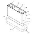
本発明の実施形態1−1を図1ないし図5を参照しつつ説明する。本実施形態に係る単電池(蓄電素子)10は、ケース11内に発電要素(蓄電要素)12を収容してなる。以下の説明においては、図2の上方を上方とし、下方を下方として説明する。
Embodiment 1-1 of the present invention will be described with reference to FIGS. A single battery (storage element) 10 according to the present embodiment is configured by housing a power generation element (storage element) 12 in a
図4に示すように、ケース11は複数の壁部を有し、扁平な略直方体形状をなしている。ケース11は上方に開口する開口部13が形成されたケース本体14と、ケース本体14に組み付けられてケース11の開口部13を塞ぐ蓋部材15と、を備える。ケース本体14は金属製であって、アルミニウム、アルミニウム合金、ステンレス等、必要に応じて任意の金属を使用できる。
As shown in FIG. 4, the
蓋部材15には、図4における左右両端部寄りの位置に、発電要素12と電気的に接続された2つの電極端子16,16が上方に突出して形成されている。電極端子16は正極端子と、負極端子とからなる。詳細には図示しないが、正極端子は、発電要素12の正極板と電気的に接続されており、負極端子は、発電要素12の負極板と電気的に接続されている。
Two
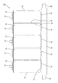
図5に示すように、発電要素12は、正極板と、負極板とを、セパレータを介して積層したものを巻回してなる。本実施形態においては、1つのケース11内に2つの発電要素12,12が収容されている。
As shown in FIG. 5, the
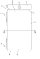
図2に示すように、ケース11の外面は、電極端子16が形成された端子面17(図2における上面)と、端子面17と反対側に位置する底面18(図2における下面)と、比較的に面積の大きな長側面19と、比較的に面積の小さな短側面20と、を備える。端子面17、底面18、長側面19、及び短側面20によりケース11の壁部が構成される。
As shown in FIG. 2, the outer surface of the
図5に示すように、ケース11内において、発電要素12は、その巻回軸が短側面20と交差する方向を向く姿勢で収容されている。2つの発電要素12,12は、ケース11の長側面19と交差する方向に並んで収容されている。また、発電要素12は、ケース11の内面のうち、底面18及び端子面17と離間した姿勢で、ケース11内に収容されている。なお、発電要素12とケース11の内面とが離間するとは、発電要素12とケース11の内面との間に緩衝部材が介在する場合も含まれる。
As shown in FIG. 5, in the
ケース11の内部には、有機溶媒を含む電解質(図示せず)が充填されている。有機溶媒としては、例えば、エチレンカーボネート、プロピレンカーボネート、ブチレンカーボネート、ジメチルカーボネート、ジエチルカーボネート、エチルメチルカーボネート、γ−ブチロラクトン、γ−バレロラクトン、酢酸メチル、プロピオン酸メチル、テトラヒドロフラン、2−メチルテトラヒドロフラン、テトラヒドロピラン、ジメトキシエタン、ジメトキシメタン、リン酸エチレンメチル、リン酸エチルエチレン、リン酸トリメチル、リン酸トリエチルなどを使用することができる。これらの有機溶媒は、一種類だけを選択して使用してもよいし、二種類以上を組み合わせて用いてもよい。
The
電解質の溶質としては、LiClO4、LiPF6、LiBF4等の無機リチウム塩や、LiCF3SO3、LiN(CF3SO2 )2、LiN(CF3CF2SO2 )2、およびLiC(CF3SO2 )3等の含フッ素有機リチウム塩等を挙げることができる。これらの溶質は、一種類だけを選択して使用してもよいし、二種類以上を組み合わせて用いてもよい。 Solutes of the electrolyte include inorganic lithium salts such as LiClO 4 , LiPF 6 , LiBF 4 , LiCF 3 SO 3 , LiN (CF 3 SO 2 ) 2 , LiN (CF 3 CF 2 SO 2 ) 2 , and LiC (CF And fluorine-containing organic lithium salts such as 3 SO 2 ) 3 . Only one type of these solutes may be selected and used, or two or more types may be used in combination.
ケース11の底面18には、合成樹脂製の伝熱部材21が、ケース11の底面18と接触した状態で配されている。伝熱部材21は弾性変形可能であって、且つ絶縁性の合成樹脂からなる。また、伝熱部材21は、空気よりも熱伝導性が高い材料からなる。本実施形態においては、熱伝導率が0.2W/m・K〜5.0W/m・Kの材料が用いられている。伝熱部材21は、66ナイロン等のポリアミド、アクリル樹脂、シリコーン樹脂、ポリエステル樹脂、ポリオレフィン樹脂等、必要に応じて任意の合成樹脂を使用しうる。
On the
本実施形態に係る伝熱部材21は厚さ1mmのシート状をなしている。伝熱部材21は略長方形状をなしており、ケース11の底面18よりもやや小さな形状に形成されている。本実施形態においては伝熱部材21の厚さは1mmとしたが、これに限られず、必要に応じて任意の厚さに形成することができる。
The
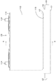
伝熱部材21の下面には、冷却部材22が配されている。伝熱部材21の下面と、冷却部材22の上面とは接触している。冷却部材22は、略直方体形状をなしており、伝熱部材21よりもやや大きな形状に形成されている。少なくとも冷却部材22の外面は銅、銅合金、ステンレス、アルミニウム、アルミニウム合金等の金属からなる。本実施形態においては銅が用いられている。
A cooling
図4に示すように、冷却部材22の内部には、冷媒(図示せず)が流通される流通路23が形成されている。冷却部材22には、流通路23と連通すると共に冷媒が流通路23内に流入する流入口24と、冷媒が流通路23外に流通する流出口25と、が形成されている。流入口24又は流出口25は、図示しないパイプ55を介して図示しないポンプに接続されており、パイプ55、流入口24、流通路23、流出口25、パイプ55の順に冷媒が流通されるようになっている。
As shown in FIG. 4, a
本実施形態においては、冷媒としては、水、有機溶媒、オイル等の液体が用いられている。冷媒としては、例えば、水、鉱油、アルキルベンゼン、ポリブテン、アルキルナフタレン、アルキルジフェニルエタン、シリコーン油、エチレングリコール等、必要に応じて任意の液体を使用しうる。 In the present embodiment, a liquid such as water, an organic solvent, or oil is used as the refrigerant. As the refrigerant, for example, water, mineral oil, alkylbenzene, polybutene, alkylnaphthalene, alkyldiphenylethane, silicone oil, ethylene glycol, etc., any liquid can be used as necessary.
伝熱部材21は、粘着性を有する材料で形成されてもよい。また、伝熱部材21の表面に粘着剤層を形成してもよい。また、伝熱部材21と、ケース11の底面18及び冷却部材22の外面とを接着剤層を介して接着してもよい。上記の構成により、伝熱部材21と、ケース11の底面18及び冷却部材22とを確実に接触させることができる。
The
(作用、効果)
続いて、本実施形態の作用、効果について説明する。本実施形態に係る単電池10においては、ケース11の底面18と冷却部材22の上面との間には伝熱部材21が配されている。この伝熱部材21はケース11の外面と接触すると共に冷却部材22の外面とも接触している。また、伝熱部材21は、弾性変形可能であって、且つ、空気よりも熱伝導率が高い合成樹脂からなる。
(Function, effect)
Then, the effect | action and effect of this embodiment are demonstrated. In the
単電池10を充電すると、発電要素12が膨張する場合がある。すると、膨張した発電要素12の押圧されることによりケース11も膨張する。すると、ケース11の外面に接触する伝熱部材21は、ケース11の外面と冷却部材22の外面との間に挟まれた状態で、ケース11の外面に押圧される。この伝熱部材21は弾性変形可能なので、ケース11の外面に押圧されることにより弾性変形する。これにより、ケース11の外面と伝熱部材21の外面とが接触した状態のまま保持されると共に、伝熱部材21の外面と冷却部材22の外面との間も、接触状態が保持される。この結果、充電時又は放電時に発電要素12で発生した熱は、ケース11、伝熱部材21、及び冷却部材22と伝達されるから、単電池10が局所的に高温になることを抑制できる。
When the
一方、放電時には発電要素12は収縮し、これに伴ってケース11も収縮する。このとき、伝熱部材21は弾性変形可能なので、収縮したケース11の外面に追従して復帰変形する。これにより、ケース11の外面と伝熱部材21の外面とは、接触した状態のまま保持される。この結果、充電及び放電が繰り返されて、ケース11が膨張及び収縮を繰り返しても、ケース11の外面、伝熱部材21の外面、及び冷却部材22の外面は接触した状態に保持される。これにより、ケース11が膨張及び収縮を繰り返しても、充電時又は放電時に発電要素12で発生した熱はケース11から伝熱部材21を介して冷却部材22に確実に伝達されるので、単電池10が局所的に高温になることを抑制できる。
On the other hand, the
また、本実施形態においては冷却部材22の外面は比較的に硬い金属からなるので、外部からの圧力に対して変形しにくい。このため、ケース11が膨張することによって、伝熱部材21を介して冷却部材22が押圧された場合でも、冷却部材22が変形することを抑制できる。この結果、冷媒の流通路23が変形することを抑制できるので、冷却部材22の内部を流通する冷媒に圧力損失が発生することを抑制できる。これにより、冷却部材22の冷却効率が低下することを抑制できる。
Further, in the present embodiment, the outer surface of the cooling
また、本実施形態においては、冷媒として液体が用いられている。これにより、空気を冷媒としたいわゆる空冷に比べて、冷却効率が外気温に左右されないという優れた効果を得ることができる。 In the present embodiment, a liquid is used as the refrigerant. Thereby, compared with what is called air cooling which used air as the refrigerant | coolant, the outstanding effect that cooling efficiency is not influenced by external temperature can be acquired.
また、空冷の場合には、外気の流入に伴って異物が冷却部材22の内部に侵入することが懸念される。これに対して上記態様によれば、冷媒が液体とされているので、冷却部材22の内部に異物が侵入することを抑制できる。
In the case of air cooling, there is a concern that foreign matter may enter the cooling
また、本実施形態においては、ケース11内には、有機溶媒を含む電解質が充填されている。このように電解質が有機溶媒を含む場合、比較的に高い温度で単電池を使用すると、有機溶媒が分解したガスが発生することが懸念される。すると、ケース11内部の圧力が上昇し、充放電サイクル数が増大するにつれて、次第にケース11が膨張することが懸念される。このような場合においても、伝熱部材21は弾性変形可能な材料からなるので、ケース11の膨張に追従して変形することができる。この結果、ケース11の外面、伝熱部材21の外面、及び冷却部材22の外面を、接触した状態を保持できる。これにより、充放電サイクル数が増大しても、単電池10が局所的に高温になることを確実に抑制できる。
In the present embodiment, the
また、本実施形態においては、伝熱部材21は底面18と接触している。ケース11の長側面19は比較的に面積が広いので、ケース11内部の圧力が上昇した時に、底面18及び短側面20に比べて大きく変形する。このため、伝熱部材21を、長側面19とは異なる底面18と接触させることにより、ケース11の外面と伝熱部材21とを接触させた状態に確実に保持することができる。
In the present embodiment, the
一方、電極端子16が形成された端子面17には、伝熱部材21及び冷却部材22を電極端子16と絶縁された状態で取り付けるためのスペースが十分に確保できない場合がある。このため、端子面17に伝熱部材21を取り付けようとすると、ケース11の外面と伝熱部材21との間に十分な接触面積を確保できないことが懸念される。上記の態様によれば、伝熱部材21を底面18に接触させることにより、ケース11の外面と伝熱部材21との間に十分な接触面積を確保できる。
On the other hand, on the
また、上記の発電要素12は、充電時に膨張することが懸念される。このため、発電要素12とケース11の内面とが接触している部分においては、膨張した発電要素12によりケース11が押圧されて、ケース11が膨張することが懸念される。
Moreover, there is a concern that the
そこで本実施形態においては、伝熱部材21は、ケース11の壁面のうち、発電要素12との間隔が比較的に大きな底面18と接触する構成とされている。これにより、ケース11の壁面のうち発電要素12との間隔が比較的大きな壁面と、伝熱部材21とが接触するようになっている。これにより、発電要素12が膨張した場合でも、伝熱部材21と接触するケース11の壁面は、発電要素12とは離間しているので、膨張した発電要素12によって押圧されることが抑制される。この結果、発電要素12が膨張した場合でも、ケース11の外面と伝熱部材21とが接触した状態を確実に保持することができる。
Therefore, in the present embodiment, the
また、発電要素12においては電位が発生するので、発電要素12とケース11との間には電位が発生する。このため、ケース11と冷却部材22との間にも電位が発生する。すると、ケース11と冷却部材22との間に電流が流れることにより、ケース11又は冷却部材22が腐食することが懸念される。そこで本実施形態においては、伝熱部材21は絶縁性材料からなる構成とした。これにより、ケース11と冷却部材22との間に電流が流れることが抑制される。この結果、ケース11又は冷却部材22が電流により腐食されることが抑制される。
Further, since a potential is generated in the
<実施形態1−2>
次に、本発明の実施形態1−2を図6ないし図8を参照しつつ説明する。本実施形態においては、ケース11の短側面20に伝熱部材31が接触する構成とされている。伝熱部材31は略長方形状をなしており、ケース11の短側面20よりもやや小さな形状とされている。
<Embodiment 1-2>
Next, Embodiment 1-2 of the present invention will be described with reference to FIGS. In the present embodiment, the
伝熱部材31には、ケース11の短側面20と反対側の面に、冷却部材32が配されている。伝熱部材31は、ケース11の短側面20と、冷却部材32の双方と接触している。
The
上記以外の構成については、実施形態1−1と略同様なので、同一部材については同一符号を付し、重複する説明を省略する。 Since the configuration other than the above is substantially the same as that of Embodiment 1-1, the same members are denoted by the same reference numerals, and redundant description is omitted.
続いて、本実施形態の作用、効果について説明する。図7に示すように、本実施形態においては、伝熱部材31は、比較的に面積の大きな長側面19とは異なる短側面20と接触している。これにより、ケース11の外面と伝熱部材31とを接触させた状態に確実に保持することができる。
Then, the effect | action and effect of this embodiment are demonstrated. As shown in FIG. 7, in this embodiment, the
また、図8に示すように、本実施形態においては、発電要素12は、その巻回軸が、短側面20と交差する方向を向く姿勢でケース11内に収容されている。充電及び放電を繰り返した場合、発電要素12はその巻回軸の径方向の外方について膨張及び収縮を繰り返す。しかし、発電要素12の変形量は、その軸方向については比較的に小さい。このため、本実施形態においては、発電要素12が膨張しても、発電要素12の軸方向の外方に位置するケース11の短側面20に対しては、発電要素12から押圧力が加わりにくくなっている。伝熱部材31は、ケース11の短側面20と接触しているので、発電要素12が膨張した場合でも、ケース11の外面と伝熱部材31とが接触した状態を確実に保持することができる。
As shown in FIG. 8, in the present embodiment, the
<実施形態1−3>
次に、本発明の実施形態1−3を図9及び図10を参照しつつ説明する。本実施形態においては、ケース11の長側面19に伝熱部材41が接触する構成とされている。伝熱部材41は略長方形状をなしており、ケース11の長側面19よりもやや小さな形状とされている(図9参照)。
<Embodiment 1-3>
Next, Embodiments 1-3 of the present invention will be described with reference to FIGS. In the present embodiment, the
伝熱部材41には、ケース11の長側面19と反対側の面に、冷却部材42が配されている。伝熱部材41は、ケース11の長側面19と、冷却部材42の双方と接触している(図10参照)。
In the
上記以外の構成については、実施形態1−1と略同様なので、同一部材については同一符号を付し、重複する説明を省略する。 Since the configuration other than the above is substantially the same as that of Embodiment 1-1, the same members are denoted by the same reference numerals, and redundant description is omitted.
本実施形態においては、長側面19と伝熱部材41とが接触しており、且つ、伝熱部材41と冷却部材42とが接触している。これにより、充電時及び放電時において発電要素12で発生した熱は、比較的に面積の大きな長側面19から伝熱部材41へと伝達され、この伝熱部材41から冷却部材42へと伝達される。ケース11の長側面19は、ケース11のうち最も面積が大きな面となっている。長側面19は、ケース11のうち面積が最も広い面なので、効率よく発電要素12を冷却することができる。
In the present embodiment, the
なお、上述したように、長側面19は、ケース11のうち面積が最も広い面なので、ケース11が、その内部の圧力上昇により膨張した場合、最も変形しやすい面となっている。上記の点に鑑み、本実施形態においては、この長側面19に、弾性変形可能な伝熱部材41が接触する構成となっている。これにより、長側面19が変形した場合でも、伝熱部材41が弾性変形することによって長側面19の変形に追従するようになっている。この結果、長側面19と伝熱部材41とが接触する状態が保持されるので、単電池10が局所的に高温になることを抑制できる。
As described above, the
<実施形態1−4>
次に、本発明の実施形態1−4を図11及び図12を参照しつつ説明する。図12に示すように、本実施形態に係る組電池(蓄電装置)56は、複数の単電池10を並べ、電気的に接続してなる。各単電池10は、直列又は並列に接続されている。複数の単電池10は、バンド等の公知の手法により、並べられた状態で固定されている。
<Embodiment 1-4>
Next, Embodiment 1-4 of this invention is demonstrated, referring FIG.11 and FIG.12. As shown in FIG. 12, the assembled battery (power storage device) 56 according to the present embodiment is formed by arranging a plurality of
また、図11に示すように、本実施形態に係る組電池56は、電気自動車、ハイブリッド自動車等の車両53に搭載されて、電源として使用される。車両53にはラジエータ54が配されている。ラジエータ54と、冷却部材52とは、パイプ55で接続されている。ラジエータ54、パイプ55、及び冷却部材52の内部には、ラジエータ液(図示せず)が流通されている。ラジエータ液としては、水、エチレングリコール等の不凍液、又は水と不凍液との混合物等、必要に応じて任意の液体を使用しうる。
As shown in FIG. 11, the assembled
図12に示すように、組電池56は、複数の単電池10を、その長側面19同士を対向させた姿勢で並べて形成されている。複数の単電池10は、1つの冷却部材52の上面に、1つの伝熱部材51を介して載置されている。
As shown in FIG. 12, the assembled
なお、単電池10に関する上記以外の構成については、実施形態1−1と略同様なので、同一部材については同一符号を付し、重複する説明を省略する。
In addition, since it is as substantially the same as Embodiment 1-1 about the structure except the above regarding the
本実施形態によれば、冷媒として車両53に用いられるラジエータ液を使用できるので、冷却部材52に流通される冷媒を別途用意する必要がない。
According to the present embodiment, since the radiator liquid used in the
なお、本実施形態においては、1つの伝熱部材51の上面に複数の単電池10を載置する構成としたが、各伝熱部材51の上面に各単電池10を載置する構成としてもよい。
In addition, in this embodiment, although it was set as the structure which mounts the
<実施形態1−5>
次に、本発明の実施形態1−5を、図13を参照しつつ説明する。図13に示すように、本実施形態に係る組電池66は、複数の単電池10を、その長側面19同士を対向させた姿勢で並べて形成されている。複数の単電池10は、一対の伝熱部材61,61によって挟まれている。伝熱部材61は、各単電池10の短側面20と接触している。
<Embodiment 1-5>
Next, Embodiment 1-5 of the present invention will be described with reference to FIG. As shown in FIG. 13, the assembled
各伝熱部材21のうち単電池10と反対側の面には、それぞれ冷却部材62が配されている。全体として、複数の単電池10は、一対の冷却部材62,62の間に、一対の伝熱部材61,61を介して挟まれた状態になっている。
A cooling
上記以外の構成については、実施形態1−4と略同様なので、同一部材については同一符号を付し、重複する説明を省略する。 Since the configuration other than the above is substantially the same as that of the embodiment 1-4, the same reference numerals are given to the same members, and duplicate descriptions are omitted.
<実験例>
続いて、本実施形態に係る単電池の冷却効果を示す実験例について説明する。本実施形態においては、単電池として(株)リチウムエナジージャパン製、LEV50(電池容量50Ah)を用いた。
<Experimental example>
Then, the experiment example which shows the cooling effect of the cell which concerns on this embodiment is demonstrated. In the present embodiment, LEV50 (
(電池1A)
電池1Aとしては、単電池の底面に伝熱部材を配し、伝熱部材の底面に冷却部材を配したものを使用した。伝熱部材としては、住友スリーエム(株)製、5580H(厚さ1.0mm、熱伝導率3W/m・K)を使用した。冷却部材は銅製のものを使用した。冷媒としては水を使用した。
(
As the
(電池1B)
電池1Bとしては、単電池の長側面に伝熱部材を配し、伝熱部材のうちケースと反対側の面に冷却部材を配したものを使用した。その他の構成については電池Bと同一とした。
(
As the
(比較例)
比較例としては、単電池に対して伝熱部材及び冷却部材の双方を配さないものを用いた。
(Comparative example)
As a comparative example, a unit in which neither a heat transfer member nor a cooling member is provided for a single cell was used.
(実験手順)
実験は、単電池1A、単電池1B、及び比較例に対し、40℃の雰囲気温度において実施した。単電池1A、及び単電池1Bについては、冷却部材の内部に、冷媒として、温度35℃、流速2.5L/minの水を流通させた。比較例については、冷却部材による冷却は行わなかった。
(Experimental procedure)
The experiment was performed at an ambient temperature of 40 ° C. for the
単電池1A、単電池1B、及び比較例について、サイクル充放電を実行し、ケースの外面における温度変化を測定した。ケースの外面における温度は、ケースの長側面に取り付けた熱電対により測定した。熱電対は、ケースの長側面のほぼ中央(対角線の交点の近傍)に取り付けた。
About
電池1A、電池1B、比較例に対する充放電は以下の条件で実行した。充放電については、定格容量の100%充放電を実行した。充電については、定電圧(1CA)、定電圧(4.1V)、充電時間4時間とし、放電については、定電流(1CA)、放電終止電圧(2.75V)とし、これを1サイクルとした。上記のサイクルを繰り返し、所定のサイクル数における電池1A、電池1B、及び比較例のケース外面の温度を測定した。結果を表1及び図14に示す。
Charging / discharging with respect to the

200サイクル終了時において、比較例(図14において●で表記)に係るケースの外面の温度は42℃に上昇したのに対し、電池1A(図14において○で表記)のケース外面の温度は39℃、電池1B(図14において△で表記)のケース外面の温度は、40℃までしか上昇しなかった。
At the end of 200 cycles, the temperature of the outer surface of the case according to the comparative example (indicated by ● in FIG. 14) rose to 42 ° C., whereas the temperature of the outer surface of the case of
更に、1600サイクル終了時においては、比較例に係るケース外面の温度が51℃にまで上昇したのに対し、電池1Aは41℃までしか上昇せず、電池1Bは45℃までしか上昇しなかった。
Furthermore, at the end of 1600 cycles, the temperature of the outer surface of the case according to the comparative example rose to 51 ° C, whereas
このように、電池1A及び電池1Bにおいては、ケースの外面に弾性変形可能な伝熱部材が接触しているので、充放電サイクルの進行に伴ってケースが膨張した場合でも、伝熱部材が弾性変形してケースの変形に追従することができる。これにより、ケースの外面と伝熱部材とが接触した状態を保持できるので、ケースの外面から伝熱部材へと熱が効率よく伝達されるようになっている。この結果、充放電時に発電要素で発生した熱は、ケースから伝熱部材を経て冷却部材へと伝達されるので、電池が局所的に高温になることを抑制できる。
Thus, in the
また、ケースの底面は、ケース内に収容された発電要素と離間しているので、充放電サイクルの進行に伴って発電要素が膨張した場合でも、発電要素によってケースの底面が押圧されることが抑制される。これにより、ケースの底面が膨張することが抑制されるので、ケースの底面と伝熱部材とが確実に接触するようになっている。この結果、ケースの底面から伝熱部材へと熱が確実に伝達されるので、電池が局所的に高温になることを確実に抑制できる。 Further, since the bottom surface of the case is separated from the power generation element housed in the case, even if the power generation element expands as the charge / discharge cycle progresses, the bottom surface of the case may be pressed by the power generation element. It is suppressed. Thereby, since the bottom face of the case is suppressed from expanding, the bottom face of the case and the heat transfer member are surely in contact with each other. As a result, since heat is reliably transmitted from the bottom surface of the case to the heat transfer member, it is possible to reliably prevent the battery from being locally heated.
<他の実施形態>
本発明は上記記述及び図面によって説明した実施形態に限定されるものではなく、例えば次のような実施態様も本明細書に開示された技術的範囲に含まれる。
1−(1)伝熱部材21は、ケース11の長側面19と、ケース11の底面18との双方に接触して配される構成としてもよい。この場合、ケース11の長側面19に接触して配された伝熱部材21と、ケース11の底面18に接触して配された伝熱部材21のそれぞれに対し、冷却部材22が接触して配される。
また、伝熱部材21は、ケース11の短側面20と、ケース11の底面18の双方に接触して配される構成としてもよい。この場合、ケース11の短側面20に接触して配された伝熱部材21と、ケース11の底面18に接触して配された伝熱部材21のそれぞれに対し、冷却部材22が接触して配される。
更に、伝熱部材21は、ケース11の長側面19と、ケース11の短側面20と、ケース11の底面18に接触して配される構成としてもよい。この場合、上記したケース11の各面に接触して配された伝熱部材21のそれぞれに対し、冷却部材22が接触して配される。
<Other embodiments>
The present invention is not limited to the embodiments described with reference to the above description and drawings. For example, the following embodiments are also included in the technical scope disclosed in the present specification.
1- (1) The
Further, the
Further, the
1−(2)本実施形態においては、冷媒は液体が使用されたが、これに限られず、冷媒は空気でもよい。 1- (2) In the present embodiment, a liquid is used as the refrigerant. However, the present invention is not limited to this, and the refrigerant may be air.
1−(3)伝熱部材21は、端子面17に接触して配される構成としてもよい。
1- (3) The
1−(4)ケース11の壁面のうち、ケース11内に収容された発電要素12が接触する壁面と、伝熱部材21の外面とが接触する構成としてもよい。
1- (4) Of the wall surfaces of the
1−(5)本実施形態においては、発電要素12は巻回型であったが、これに限られず、発電要素12は、正極板、セパレータ、及び負極板を積層してなるスタック型でもよい。
1- (5) In the present embodiment, the
1−(6)実施形態1−2においては、伝熱部材31はシート状をなす構成としたが、これに限られない。図15に示すように、伝熱部材71としては、基部73から突出する弾性変形可能な弾性変形部74を備える構成としてもよい。この伝熱部材73は、ケース11の外面に基部73を接触させ、弾性変形部74の先端を冷却部材32の外面に接触させる構成としてもよい。弾性変形部74は、弾性変形した状態で、冷却部材32の外面と接触している。これにより、ケース11が膨張しても、弾性変形部74が弾性変形することによりケース11の変形に追従することができる。また、伝熱部材71は、冷却部材32の外面に基部73を接触させ、弾性変形部74の先端をケース11の外面に接触させる構成としてもよい。
1−(7)電池モジュールは車両53に搭載される構成に限られず、船舶、航空機等、必要に応じて任意の乗り物に搭載されてこれらの電源として使用してもよい。また、例えば緊急用電源等、必要に応じて任意の機器の電源として使用できる。
1- (6) In Embodiment 1-2, the
1- (7) The battery module is not limited to the configuration mounted on the
1−(8)本実施形態においては、冷却部材の内部には冷媒が流通される構成としたが、必ずしも冷媒が流通される構成でなくてもよい。冷却部材としては、例えば複数のフィンが設けられた金属板であってもよく、また、平坦な表面を有する金属板であってもよい。 1- (8) In the present embodiment, the refrigerant is circulated inside the cooling member. However, the refrigerant may not necessarily be circulated. The cooling member may be, for example, a metal plate provided with a plurality of fins, or may be a metal plate having a flat surface.
1−(9)本実施形態においては、蓄電素子として充放電可能な単電池としたが、これに限られず、電気化学キャパシタ、電気二重層キャパシタ等のキャパシタであってもよい。 1- (9) In the present embodiment, a single battery that can be charged and discharged is used as a power storage element. However, the present invention is not limited to this, and a capacitor such as an electrochemical capacitor or an electric double layer capacitor may be used.
1−(10)ケースの壁部の内面と蓄電要素が離間する構成には、ケースの壁部の内面と蓄電要素との間に隙間が形成される場合が含まれ、また、ケースの壁部の内面と蓄電要素との間に緩衝材が介在することにより、ケースと蓄電要素とが直接には接触していない構成も含まれる。 1- (10) The configuration in which the inner surface of the wall portion of the case and the power storage element are separated includes a case where a gap is formed between the inner surface of the wall portion of the case and the power storage element. A configuration is also included in which the case and the power storage element are not in direct contact with each other because the buffer material is interposed between the inner surface of the battery and the power storage element.
<実施形態2−1>
(背景技術)
<Embodiment 2-1>
(Background technology)
電気自動車などにおいては、複数個の単電池を並べてなる組電池が搭載される。このような組電池を冷却するために、例えば特開2000−294302号公報においては、冷却風(空気)を流すことが提案されている。 In an electric vehicle or the like, an assembled battery in which a plurality of single cells are arranged is mounted. In order to cool such an assembled battery, for example, Japanese Patent Application Laid-Open No. 2000-294302 proposes flowing cooling air (air).
この特開2000−294302号公報に記載の組電池においては、組電池を構成する電池モジュールを間隔をあけて並べるとともに、電池モジュールを構成する複数の単電池を間隔をあけて並べることで、冷却流路を形成している。
(本明細書に開示された技術の概要)
(本明細書に開示された技術が解決しようとする課題)
In the assembled battery described in Japanese Unexamined Patent Publication No. 2000-294302, the battery modules constituting the assembled battery are arranged at intervals, and a plurality of single cells constituting the battery module are arranged at intervals, thereby cooling the battery. A flow path is formed.
(Outline of the technology disclosed in this specification)
(Problems to be solved by the technology disclosed in this specification)
上記特開2000−294302号公報に記載の組電池のように、単電池や電池モジュールの間隔をあけることにより形成された冷却流路を備える組電池において、冷却効率を上げるために、単電池の間隔や電池モジュールの間隔を大きくすると、組電池を搭載するために大きなスペースが必要となる。一方、単電池の間隔や電池モジュールの間隔を小さくすると、冷却風が流通しにくくなって組電池を構成する複数の単電池に均一に冷却風を当てることが困難となり、電池温度にばらつきが発生する。また、単電池が使用により膨れて単電池間の間隔や電池モジュールの間隔がさらに小さくなるため冷却風の流通が悪化し冷却性能が低下するという問題がある。 In order to increase the cooling efficiency in an assembled battery including a cooling channel formed by providing a gap between the cells and the battery module as in the assembled battery described in the above-mentioned JP-A-2000-294302, When the interval and the interval between the battery modules are increased, a large space is required for mounting the assembled battery. On the other hand, if the interval between the single cells or the interval between the battery modules is reduced, it becomes difficult for the cooling air to flow and it becomes difficult to uniformly apply the cooling air to the plurality of single cells constituting the assembled battery, resulting in variations in the battery temperature. To do. In addition, since the cells are swollen by use and the distance between the cells and the distance between the battery modules are further reduced, there is a problem that the circulation of the cooling air is deteriorated and the cooling performance is lowered.
本明細書に開示された技術は上記のような事情に基づいて完成されたものであって、省スペースでありながらも冷却性能が優れた蓄電装置を提供することを目的とする。
(課題を解決するための手段)
The technology disclosed in this specification has been completed based on the above-described circumstances, and an object thereof is to provide a power storage device that is space-saving and has excellent cooling performance.
(Means for solving the problem)
上記課題を解決するものとして本明細書に開示された技術は、蓄電要素と、前記蓄電要素を収容するとともに電極端子が突出形成されたケースと、前記ケースの外側に配置され、前記ケースを冷却する冷却部材と、を備える蓄電素子であって、前記冷却部材は、前記ケースの前記電極端子が形成された端子面を除く面のうち、面積が最も広い面以外の面と、直接または間接的に接触するように配されているところに特徴を有する。また、本明細書に開示された技術は、前記蓄電素子を複数個並べてなる蓄電装置である。 The technology disclosed in the present specification as a solution to the above-described problem includes a power storage element, a case in which the power storage element is accommodated and an electrode terminal protrudes, and is disposed outside the case to cool the case. A cooling member, wherein the cooling member includes a surface other than the surface having the largest area among the surfaces other than the terminal surface on which the electrode terminal of the case is formed, directly or indirectly. It is characterized by being arranged so as to come into contact with. The technology disclosed in the present specification is a power storage device in which a plurality of the power storage elements are arranged.
本明細書に開示された技術においては、冷却部材をケースの面に直接または間接的に接触するように配するので、蓄電素子間の間隔をあけることで冷却流路を形成する場合のように、冷却効率を向上するために間隔を大きくする必要はないので省スペースである。 In the technology disclosed in this specification, the cooling member is arranged so as to be in direct or indirect contact with the surface of the case, so that the cooling flow path is formed by providing a space between the storage elements. The space is saved because there is no need to increase the interval in order to improve the cooling efficiency.
ところで、蓄電装置を構成する蓄電素子は、蓄電要素の膨らみや電池内圧の上昇などに起因して膨らむ。そのため、冷却部材を例えば扁平角形のケースの面に直接あるいは間接的に接触するように配置した後に蓄電素子が膨らむことで、ケースの面と冷却部材との接触面積が小さくなると、冷却部材による冷却効果が充分に得られなくなることに起因して、蓄電素子に対する冷却効果が低下し、また蓄電装置とした場合には、蓄電装置内の温度分布が不均一となることがある。 By the way, the power storage element constituting the power storage device expands due to expansion of the power storage element, increase in battery internal pressure, or the like. For this reason, if the contact area between the surface of the case and the cooling member is reduced due to the expansion of the storage element after the cooling member is disposed so as to be in direct or indirect contact with the surface of the flat rectangular case, for example, the cooling by the cooling member Due to the fact that the effect cannot be obtained sufficiently, the cooling effect on the power storage element is reduced, and in the case of the power storage device, the temperature distribution in the power storage device may be non-uniform.
蓄電素子のケースの面のうち、最も面積が広い面は、蓄電素子が膨らんだ際に最も膨らみやすい面であるので、この面にのみ冷却部材を配すると、冷却部材との接触面積が小さくなり冷却部材による冷却効果が十分に得られなくなることが懸念される。 Of the surfaces of the storage element case, the surface with the largest area is the surface that is most likely to expand when the storage element expands.If a cooling member is disposed only on this surface, the contact area with the cooling member is reduced. There is a concern that the cooling effect of the cooling member cannot be sufficiently obtained.
しかし、本明細書に開示された技術において、冷却部材は、ケースの面のうち、最も面積が広い面以外の面と、直接または間接的に配されているから、膨らみにくい面と接触するように配されている。つまり本明細書に開示された技術では、蓄電素子自体が膨らんだとしても、冷却部材はケースの膨らみにくい面に接触するように配されているから、冷却部材とケースの面との接触面積を大きくすることができ、冷却部材による冷却効果を充分に得ることができる。その結果、本明細書に開示された技術によれば、蓄電装置における冷却性能を向上させることができる。 However, in the technique disclosed in the present specification, the cooling member is arranged directly or indirectly with a surface other than the surface having the largest area among the surfaces of the case, so that the cooling member comes into contact with a surface that does not easily swell. It is arranged in. That is, in the technology disclosed in this specification, even if the power storage element itself swells, the cooling member is arranged so as to contact the surface of the case that is difficult to swell, so the contact area between the cooling member and the surface of the case is reduced. The cooling effect of the cooling member can be sufficiently obtained. As a result, according to the technology disclosed in this specification, the cooling performance of the power storage device can be improved.
本明細書に開示された技術は以下の構成であってもよい。前記冷却部材は、冷媒を流通させることで前記電池ケースを冷却する部材であってもよい。 The technology disclosed in this specification may have the following configuration. The cooling member may be a member that cools the battery case by circulating a refrigerant.
前記冷媒は、車両のラジエータ液であってもよい。このような構成とすると、本明細書に開示された技術に係る蓄電素子を用いた蓄電装置が、ラジエータを備えた自動車に搭載される場合に、冷媒としてラジエータ液が好適に使用できる。自動車に用いられるラジエータ液を使用できる場合には、冷却部材に流通される冷媒を別途用意する必要がない。なお、ラジエータ液はエチレングリコール等の不凍液を含んでもよい。 The refrigerant may be a vehicle radiator liquid. With such a configuration, when a power storage device using the power storage element according to the technology disclosed in this specification is mounted on an automobile including a radiator, a radiator liquid can be preferably used as the refrigerant. When the radiator liquid used in the automobile can be used, it is not necessary to separately prepare a refrigerant to be circulated through the cooling member. The radiator liquid may include an antifreeze liquid such as ethylene glycol.
前記冷却部材と前記ケースとの間には、空気よりも熱伝導率が高く弾性変形可能な材料からなる熱伝導部材が配されていてもよい。 Between the cooling member and the case, a heat conduction member made of a material having higher heat conductivity than air and capable of elastic deformation may be disposed.
蓄電素子の使用により、冷却部材が配置されているケースの面が変形すると、ケースと冷却部材との接触面積が小さくなり冷却効果の低下が懸念される。 When the surface of the case where the cooling member is disposed is deformed due to the use of the power storage element, the contact area between the case and the cooling member is reduced, and there is a concern that the cooling effect may be reduced.
そこで、上記のような構成とすると、ケースの変形に追従して熱伝導部材が変形するので、蓄電素子の長期使用によりケースが変形したとしても、ケースと冷却部材との接触面積を大きく保つことができ、冷却効果の低下を防止することができる。 Therefore, with the above configuration, the heat conducting member is deformed following the deformation of the case, so that the contact area between the case and the cooling member is kept large even if the case is deformed due to long-term use of the power storage element. And a reduction in cooling effect can be prevented.
前記熱伝導部材は絶縁性を有していてもよい。例えば、蓄電素子のケースが金属製で熱伝導部材が非絶縁性の材料から構成されている場合、ケースと熱伝導部材とが導通して腐食する等、安全面の懸念がある。しかし、上記のような構成とすると、蓄電素子のケースが金属製の場合でも、熱伝導部材と導通することがないので、安全性を高めることができる。 The heat conducting member may have an insulating property. For example, when the case of the power storage element is made of metal and the heat conducting member is made of a non-insulating material, there is a concern about safety, such as the case and the heat conducting member conducting and corroding. However, with the above configuration, even when the case of the power storage element is made of metal, it is not electrically connected to the heat conducting member, so that safety can be improved.
本明細書に開示された技術に係る蓄電装置は、以下の構成としてもよい。2以上の蓄電素子につき前記冷却部材を1個設けてもよい。このような構成とすると部品点数を減らし、かつ、省スペースとすることができる。 The power storage device according to the technology disclosed in this specification may have the following configuration. One cooling member may be provided for two or more power storage elements. With such a configuration, it is possible to reduce the number of parts and save space.
2以上の蓄電素子につき前記熱伝導部材を1個設ける構成としてもよい。このような構成とすると部品点数を減らし、かつ省スペースとすることができる。
(本明細書に開示された技術の効果)
One heat conducting member may be provided for two or more power storage elements. With such a configuration, it is possible to reduce the number of parts and save space.
(Effect of the technology disclosed in this specification)
本明細書に開示された技術によれば、省スペースでありながらも冷却性能が優れた蓄電装置を提供することができる。 According to the technology disclosed in this specification, it is possible to provide a power storage device that is space-saving and has excellent cooling performance.
本発明の実施形態2−1の単電池(蓄電素子)110を、図16ないし図20によって説明する。 A single battery (storage element) 110 according to Embodiment 2-1 of the present invention will be described with reference to FIGS.
本実施形態の単電池110は、図16に示すように、直方体状(扁平角形の一例)の電池ケース(ケース)111と、電池ケース111の下方に配される熱伝導部材(伝熱部材)125と冷却部材120とを備える。
As shown in FIG. 16, the
電池ケース111の上面111Aは、図16および図17に示すように、正極端子112Aおよび負極端子112B(電極端子112)が突出形成された端子面111Aである。電池ケース111の側面111B,111Cは、図16および図18に示すように、面積の広い面111B(「長側面111B」ともいう)と面積の小さい面111C(「短側面111C」ともいう)から構成されている。電池ケース111の下側の面111Dには冷却部材120が配されるようになっている。電池ケース111の下側の面111Dを底面111Dとする。端子面111A、長側面111B、短側面111C、及び底面111Dにより電池ケース111の複数の壁部が構成される。
The
本実施形態において、電池ケース111は、ステンレスなどの金属からなり、内部には、図19に示すように、発電要素(蓄電要素)113が収容されている。発電要素113は、詳細は図示しないが、正極板と負極板とをセパレータを介して巻回してなる。本実施形態では2つの発電要素113,113が、巻回軸を短側面111Cに対して垂直な方向に配して収容されている。正極板は正極端子112Aと接続され、負極板は負極端子112Bと接続されている。
In the present embodiment, the
本実施形態においては、電池ケース111の面のうち、発電要素113からの離間距離が最も長い面は短側面111Cであり、発電要素113からの離間距離が最も短い面は長側面111Bである。電池ケース111の面のうち、面積の最も広い面は長側面111Bであり、面積の最も小さい面は短側面111Cである。
In the present embodiment, of the surfaces of the
電池ケース111の底面111Dの下側に配される冷却部材120は、図18に示すように、内部に図示しない冷媒を収容して冷媒を流通させる金属製の本体部121と、本体部121の図18に示す左側の端部に設けられた冷媒を本体部121内に導入する冷媒流入口122と、本体部121の図18に示す右側の端部に設けられた本体部121内の冷媒を本体部121外に流出させる冷媒流出口123と、を備える。
As shown in FIG. 18, the cooling
冷却部材120の本体部121内を流通する冷媒としては自動車用のラジエータ液、水、空気などがあげられる。ラジエータ液の具体例としてはエチレングリコールなどがあげられる。これらの冷媒のうち、水やラジエータ液は、外気温に左右されにくいという点で好ましい。
Examples of the refrigerant circulating in the
冷却部材120と電池ケース111の底面111Dとの間には、図18および図20に示すように、シート状の熱伝導部材(伝熱部材)125が、挟持されている。詳しくは、熱伝導部材125の上側面は電池ケース111の底面111Dと直接接触し、熱伝導部材125の下側面は冷却部材120の本体部121の上面と直接接触するように配されている。
As shown in FIGS. 18 and 20, a sheet-like heat conducting member (heat conducting member) 125 is sandwiched between the cooling
熱伝導部材125を構成する熱伝導性材料としては、空気よりも熱伝導率が高く、電池の膨れに追従して弾性変形可能な材料が挙げられる。
Examples of the heat conductive material constituting the heat
ところで、単電池110の電池ケース111が金属製で、熱伝導部材125が金属などの非絶縁材料から構成されている場合、電池ケース111と熱伝導部材125とが導通して電池ケース111が腐食する等、安全面の懸念がある。安全性を考慮すると、熱伝導性材料としては絶縁性の材料が好ましい。このような熱伝導性材料の具体例としては、ポリアミド樹脂や、アクリル樹脂などがあげられる。
By the way, when the
次に、本実施形態の作用・効果について説明する。
本実施形態によれば、冷却部材120が電池ケース111の底面111Dに熱伝導性材料を介して間接的に接触するように配されているので、単電池110の間隔をあけることで冷却流路を形成する場合のように、冷却効率を向上するために間隔を大きくする必要はないので省スペースである。
Next, functions and effects of this embodiment will be described.
According to the present embodiment, since the cooling
ところで、本実施形態において、電池ケース111の面のうち短側面111Cは、発電要素113からの離間距離が最も長いので発電要素113の膨らみの影響を受けにくいが、面積が最も小さいため冷却効率が低い。電池ケース111の底面111Dは、発電要素113からの離間距離は短側面111Cよりも若干短いが、短側面111Cよりも面積が広い面であるとともに、長側面111Bよりも面積が小さい面であるので、発電要素113が膨らんだり電池内圧が上昇したとしても膨らみにくく、冷却効率も短側面111Cより高い。したがって、本実施形態では、単電池110自体が膨らんだとしても、冷却部材120は電池ケース111の面のうち、膨らみにくい面(底面111D)に配されているから、冷却部材120と電池ケース111との接触面積を大きくすることができる。その結果、本実施形態の単電池110を用いた組電池(蓄電装置)において冷却性能を向上することができる。
By the way, in the present embodiment, the
ところで、単電池110の使用により、冷却部材120が配置されている電池ケース111の面が変形すると、電池ケース111と冷却部材120との接触面積が小さくなり冷却効果の低下が懸念される。しかしながら、本実施形態においては、冷却部材120と電池ケース111との間に、空気よりも熱伝導率が高く弾性変形可能な材料からなる熱伝導部材125が配されているから、電池ケース111の変形に追従して熱伝導部材125が変形するので、単電池110の長期使用により電池ケース111が変形したとしても、電池ケース111と冷却部材120との接触面積を大きく保つことができ、冷却効果の低下を防止することができる。
By the way, when the surface of the
<変形例2−1>
実施形態2−1の変形例を図21ないし図25により説明する。
変形例2−1の単電池30は、図21に示すように、電池ケース111と冷却部材120との間に熱伝導部材125を備えないという点で実施形態2−1と相違する。本変形例において、実施形態2−1と同様の構成については同じ符号を付して、重複する説明は省略する。
<Modification 2-1>
A modification of the embodiment 2-1 will be described with reference to FIGS.
The
変形例2−1の単電池130においては、図23〜図25に示すように、冷却部材120が電池ケース111の底面111Dと直接接触するように配される。本変形例において、上記以外の構成は、図21ないし図25に示すように、実施形態2−1の単電池110と、おおむね同じである。したがって、本変形例によっても、実施形態1と同様に、省スペースで冷却性能が向上した組電池を提供することができる。
In the
<実施形態2−2>
実施形態2−2の組電池150を図26および図27によって説明する。本実施形態の組電池150は、図26に示すように、電気自動車EVの車両後部に搭載される。本実施形態では、複数の単電池140を備える点、および、複数の単電池140に対して、1個の冷却部材160と1個の熱伝導部材165とを備えるという点で実施形態2−1と相違する。実施形態2−1と同様の構成については同じ符号を付し重複する説明は省略する。
<Embodiment 2-2>
An assembled
本実施形態の組電池150は、図27に示すように、複数個(本実施形態では5個)の単電池140を、長側面111B,111Bが対向するように並べてなる。組電池150を構成する複数の単電池140は、図示しないバスバー等の導電部材を接続することにより、電気的に接続されるようになっている。本実施形態において、冷却部材160は、電池ケース111の底面111Dと、シート状の熱伝導部材165を介して間接的に接触するように配置されている。
As shown in FIG. 27, the assembled
冷却部材160は内部に図示しない冷媒を収容して冷媒を流通させる金属製の本体部161と、本体部161の図27に示す左側の端部に設けられた冷媒を本体部161内に導入する冷媒流入口162と、本体部161の図12に示す右側の端部に設けられた本体部161内の冷媒を本体部161外に流出させる冷媒流出口163と、を備える。本実施形態において、冷媒流入口162および冷媒流出口163は単電池140の長側面111B側に配されている。
The cooling
そして、冷媒流入口162および冷媒流出口163は、図26に示すように、ラジエータRと接続されている。本実施形態において、冷却部材160の本体部161内を流通する冷媒は車用のラジエータ液である。上記以外の構成は実施形態2−1と概ね同様である。
The
次に、本実施形態の作用・効果について説明する。
本実施形態によれば、実施形態2−1と同様に、冷却部材160が、電池ケース111の面のうち、膨らみにくく、短側面111Cよりも冷却効率の高い面である底面111Dに、熱伝導部材165を介して間接的に接触するように配されるので、省スペースで温度分布が均一な組電池150を提供することができる。
Next, functions and effects of this embodiment will be described.
According to the present embodiment, similar to the embodiment 2-1, the cooling
さらに、本実施形態によれば、冷媒としてラジエータ液を用いるので、自動車用のラジエータ液と組電池150の冷却とを兼ねることができ、電池冷却用の冷媒を別途用意する必要がない。
Furthermore, according to the present embodiment, since the radiator liquid is used as the refrigerant, it is possible to serve as both the radiator liquid for the automobile and the cooling of the assembled
加えて、本実施形態によれば、2以上の単電池140につき冷却部材160を1個設けており、かつ、2以上の単電池140につき熱伝導部材165を1個設けているので、部品点数を減らすことができるうえに省スペースである。
In addition, according to the present embodiment, one cooling
<実施例>
以下、実施例によりさらに本発明を具体的に説明する。
1.単電池の作製
<Example>
Hereinafter, the present invention will be described more specifically with reference to examples.
1. Cell fabrication
(単電池2A)
図28及び図29に示すように、(株)リチウムエナジージャパン製のリチウムイオン電池(品番:LEV50、電池容量50Ah)の直方体状をなす電池ケース111の側面のうち、面積の小さい面111C(短側面111C)に、1セル用の冷却部材120を直接接触するように配置したものを単電池2A(図中、符号110A)とした。図28および図29において、実施形態2−1と同様の構成については同じ符号を付した。
(Single cell 2A)
As shown in FIG. 28 and FIG. 29, among the side surfaces of a
(単電池2B)
図30及び図31に示すように、電池ケース111の短側面111Cと冷却部材120との間に熱伝導部材125(アクリル系の熱伝導性ジェルシート、住友スリーエム製、品番5580H、熱伝導率3W/m・K、厚み1.0mm)を配置したこと以外は単電池2Aと同様にして比較例2−3の単電池2B(図中、符号110B)を得た。図30および図32において、実施形態2−1と同様の構成については同じ符号を付した。
(Single cell 2B)
As shown in FIGS. 30 and 31, between the
(単電池2C)
電池ケース111の底面111Dに、1セル用の冷却部材120を接触するように配置したこと以外は単電池2Aと同様にして単電池2Cを得た(図21及び図23参照)。
(Single cell 2C)
A unit cell 2C was obtained in the same manner as the unit cell 2A except that the cooling
(単電池2D)
電池ケース111の底面111Dと冷却部材120との間に熱伝導部材125を配置したこと以外は単電池2Cと同様にして単電池2Dを得た(図16及び図18参照)。
(Single cell 2D)
A unit cell 2D was obtained in the same manner as the unit cell 2C except that the
(比較例2−1の単電池)
冷却部材120および熱伝導部材125を配置しないリチウムイオン電池[(株)リチウムエナジージャパン製のリチウムイオン電池(品番:LEV50)]を比較例2−1の単電池とした。
(Single cell of Comparative Example 2-1)
A lithium ion battery [lithium ion battery (product number: LEV50) manufactured by Lithium Energy Japan Co., Ltd.] in which the cooling
(比較例2−2の単電池)
図32及び図33に示すように、(株)リチウムエナジージャパン製のリチウムイオン電池(品番:LEV50、電池容量50Ah)の直方体状をなす電池ケース111の側面のうち、面積の広い面111B(長側面111B)に、1セル用の冷却部材120を直接接触するように配置したものを比較例2−2の単電池1Aとした。図32および図33において、実施形態2−1と同様の構成については同じ符号を付した。
(Single cell of Comparative Example 2-2)
As shown in FIG. 32 and FIG. 33, the
(比較例2−3の単電池)
図34及び図35に示すように、電池ケース111の長側面111Bと冷却部材120との間に熱伝導部材125(アクリル系の熱伝導性ジェルシート、住友スリーエム製、品番5580H、熱伝導率3W/m・K、厚み1.0mm)を配置したこと以外は単電池2Aと同様にして比較例2−3の単電池1Bを得た。図34および図35において、実施形態2−1と同様の構成については同じ符号を付した。
(Single cell of Comparative Example 2-3)
As shown in FIGS. 34 and 35, between the
2.評価試験
1.で作製した単電池(単電池2A〜2D、比較例2−1〜2−3の単電池)をそれぞれ40℃の雰囲気下で、以下の方法によりサイクル試験を行った。
冷却部材120の冷媒としては、35℃の水道水を用い、流速2.5リットル/分で冷却部材120の本体部21内に流通させた。
2. Evaluation test A cycle test was performed by the following method for each of the unit cells (unit cells 2A to 2D, unit cells of Comparative Examples 2-1 to 2-3) manufactured in the above, under an atmosphere of 40 ° C.
As the refrigerant of the cooling
各単電池を、定電流(1CA)、定電圧(4.1V)で4時間充電し、定電流(1CA)、放電終止電圧2.75Vで放電をおこない、これを1サイクルとして、1600サイクルまで充放電を繰り返した。 Each cell is charged with a constant current (1CA) and a constant voltage (4.1V) for 4 hours, and discharged at a constant current (1CA) and a discharge end voltage of 2.75V. Charging / discharging was repeated.
各単電池について200サイクルごとに電池表面温度を測定し表2に示した。
なお、電池表面温度は、電池の長側面111Bのほぼ中央に熱電対を貼付して、1サイクル中の最高温度を測定した。
The cell surface temperature was measured for each unit cell every 200 cycles and shown in Table 2.
In addition, the battery surface temperature stuck the thermocouple in the approximate center of the
3.結果と考察
表2から明らかなように、冷却部材を、電池ケースの短側面と直接または間接的に接触するように配した単電池2Aおよび単電池2B、ならびに、電池ケースの底面と直接または間接的に接触するように配した単電池2Cおよび単電池2Dでは、比較例2−1〜2−3の単電池と比べて、電池表面温度の温度上昇が緩やかであった。
3. Results and Discussion As is clear from Table 2, the unit cells 2A and unit cells 2B in which the cooling member is arranged so as to be in direct or indirect contact with the short side surface of the battery case, and the bottom surface of the battery case directly or indirectly In the single battery 2C and the single battery 2D arranged so as to be in contact with each other, the temperature increase of the battery surface temperature was moderate as compared with the single batteries of Comparative Examples 2-1 to 2-3.
この結果から、本発明の単電池によれば、冷却部材による冷却効果を充分に得ることができるので、組電池における冷却性能を向上することができると考えられる。 From this result, according to the single battery of the present invention, it is considered that the cooling effect by the cooling member can be sufficiently obtained, so that the cooling performance in the assembled battery can be improved.
また、底面に冷却部材のみを配した単電池2Cでは、短側面に冷却部材のみを配した単電池2Aよりも電池表面温度の温度上昇が緩やかであり、底面に冷却部材と熱伝導シートとを配した単電池2Dでは、短側面に冷却部材と熱伝導シートを配した単電池2Bよりも電池表面温度の温度上昇が緩やかであった。 Further, in the unit cell 2C in which only the cooling member is disposed on the bottom surface, the temperature rise of the battery surface temperature is more gradual than in the unit cell 2A in which only the cooling member is disposed on the short side surface, and the cooling member and the heat conductive sheet are disposed on the bottom surface. In the unit cell 2D, the temperature increase of the battery surface temperature was more gradual than the unit cell 2B in which the cooling member and the heat conductive sheet were disposed on the short side surface.
この結果から、電池ケースの底面に冷却部材を配する方が、冷却効果が高いということが分かった。 From this result, it was found that the cooling effect is higher when the cooling member is arranged on the bottom surface of the battery case.
単電池2Aと単電池2Bとを比較すると、熱伝導シートを備える単電池2Bの方が、熱伝導シートを備えない単電池2Aよりも、400サイクル経過後の温度上昇を抑制する効果が高かった。単電池2Cと単電池2Dとの比較においても熱伝導シートを備える単電池2Dにおいて600サイクル経過後の温度上昇を抑制する効果が高かった。この結果から、熱伝導部材を備えるものでは、電池の長期使用により電池ケースが変形したとしても、電池ケースと冷却部材との接触面積を大きく保つことができ、冷却効果の低下を防止することができるということが分かった。 Comparing the unit cell 2A and the unit cell 2B, the unit cell 2B provided with the heat conductive sheet was more effective in suppressing the temperature rise after 400 cycles than the unit cell 2A provided with no heat conductive sheet. . Also in the comparison between the unit cell 2C and the unit cell 2D, the unit cell 2D provided with the heat conductive sheet was highly effective in suppressing the temperature rise after 600 cycles. From this result, it is possible to maintain a large contact area between the battery case and the cooling member even if the battery case is deformed due to long-term use of the battery, and to prevent a decrease in the cooling effect in the case of including the heat conducting member. I understood that I could do it.
<他の実施形態>
本発明は上記記述及び図面によって説明した実施形態に限定されるものではなく、例えば次のような実施態様も本明細書に開示された技術的範囲に含まれる。
2−(1)上記実施形態2−2では、電池ケース111と冷却部材160との間に熱伝導部材165を配して、電池ケース111と冷却部材160とが間接的に接触する構成を示したが、図36に示すように、電池ケース111と冷却部材160とが直接接触するような構成であってもよい。この場合、冷却部材160は、熱伝導部材を兼ねる構成となっている。図36に示す組電池170は、熱伝導部材165がないこと以外は実施形態2−2の組電池150と、おおむね同じ構成である。
<Other embodiments>
The present invention is not limited to the embodiments described with reference to the above description and drawings. For example, the following embodiments are also included in the technical scope disclosed in the present specification.
2- (1) In the above embodiment 2-2, a configuration in which the
2−(2)上記実施形態および実施例では、電池ケースの1つの面にのみ冷却部材を備える単電池及び組電池を示したが、2以上の面に冷却部材を備えていてもよい。面積の最も広い面以外の面に冷却部材を備えていれば、面積の最も広い面に冷却部材を備えるものであってもかまわない。 2- (2) In the above-described embodiments and examples, the unit cell and the assembled battery provided with the cooling member only on one surface of the battery case are shown, but the cooling member may be provided on two or more surfaces. As long as the cooling member is provided on a surface other than the surface having the largest area, the cooling member may be provided on the surface having the largest area.
2−(3)上記実施形態2−2では、5個の単電池に対して、1個の熱伝導部材を配し、かつ、5個の単電池に対し1個の冷却部材を配したものを示したが、これに限定されない。熱伝導部材および冷却部材を2つの単電池ごとに備える構成などであってもよい。また、熱伝導部材と冷却部材の数は同一でなくてもよい。 2- (3) In the above embodiment 2-2, one heat conducting member is arranged for five unit cells, and one cooling member is arranged for five unit cells. However, the present invention is not limited to this. The structure etc. which are provided with a heat conduction member and a cooling member for every two unit cells may be sufficient. Further, the number of heat conducting members and cooling members may not be the same.
2−(4)上記実施形態2−2では組電池として、5個の単電池を、長側面を対向するように並べてなるものを示したが、単電池の短側面を対向するように並べてなる組電池などであってもよい。また、組電池を構成する単電池の数は5個より多くてもよいし5個未満であってもよい。 2- (4) In the above embodiment 2-2, as the assembled battery, five unit cells are arranged so that the long side faces each other, but the short side of the unit cell is arranged so as to face each other. An assembled battery may be used. Further, the number of unit cells constituting the assembled battery may be more than five or less than five.
2−(5)上記実施形態及び実施例では直方体状の電池ケースを示したが長円筒形のものなどであってもよい。 2- (5) Although the rectangular parallelepiped battery case is shown in the above embodiment and examples, it may be a long cylindrical one.
2−(6)本実施形態においては、蓄電素子として充放電可能な単電池としたが、これに限られず、電気化学キャパシタ、電気二重層キャパシタ等のキャパシタであってもよい。 2- (6) In the present embodiment, the electric storage element is a chargeable / dischargeable unit cell, but is not limited thereto, and may be a capacitor such as an electrochemical capacitor or an electric double layer capacitor.
2−(7)電池ケースの壁部の内面と蓄電要素が離間する構成には、電池ケースの壁部の内面と蓄電要素との間に隙間が形成される場合が含まれ、また、電池ケースの壁部の内面と蓄電要素との間に緩衝材が介在することにより、電池ケースと蓄電要素とが直接には接触していない構成も含まれる。 2- (7) The configuration in which the inner surface of the wall portion of the battery case and the power storage element are separated includes a case where a gap is formed between the inner surface of the wall portion of the battery case and the power storage element. A configuration in which the buffer material is interposed between the inner surface of the wall portion and the power storage element so that the battery case and the power storage element are not in direct contact is also included.
10...単電池(蓄電素子)
11...ケース
12...発電要素(蓄電要素)
16...電極端子
17...端子面
18...底面
19...長側面
20...短側面
21,31,41,51,61...伝熱部材
22,32,42,52,62...冷却部材
53...車両
54...ラジエータ
56,66...組電池(蓄電装置)
110,130,140...単電池(蓄電素子)
111...電池ケース(ケース)
111A...端子面
111B...長側面(面積が最も広い面)
111C...短側面
111D...底面
112...電極端子
113...発電要素(蓄電要素)
120,160...冷却部材
125,165...熱伝導部材(伝熱部材)
150,170...組電池(蓄電装置)
EV...電気自動車
R...ラジエータ
10 ... Single battery (storage element)
11 ...
16 ...
110, 130, 140 ... single battery (storage element)
111 ... Battery case
111A ...
111C ...
120, 160 ... Cooling
150, 170 ... assembled battery (power storage device)
EV ... Electric car R ... Radiator
Claims (19)
正極板と、負極板とをセパレータを介して積層したものを巻回してなり、前記複数の壁のうちの前記第2の壁の内面から離間した状態で前記ケース内に収容された蓄電要素と、 A power storage element that is formed by winding a laminate of a positive electrode plate and a negative electrode plate via a separator, and is housed in the case in a state of being separated from the inner surface of the second wall of the plurality of walls. ,
充放電に伴い前記蓄電要素が膨張する間も前記蓄電要素から離間した状態が保たれている前記第2の壁の、外面と接している伝熱部材と、を備える蓄電素子。 A power storage element comprising: a heat transfer member in contact with an outer surface of the second wall, which is maintained in a state of being separated from the power storage element while the power storage element expands due to charge and discharge.
前記冷媒は液体である請求項2に記載の蓄電素子。 The electricity storage device according to claim 2, wherein the refrigerant is a liquid.
前記冷媒はラジエータ液である請求項4に記載の蓄電素子。 The electric storage element according to claim 4, wherein the refrigerant is a radiator liquid.
前記冷却部材は金属製の外表面を有する請求項6に記載の蓄電素子。 The power storage device according to claim 6, wherein the cooling member has a metal outer surface.
前記冷媒は液体である請求項6に記載の蓄電素子。 The electricity storage device according to claim 6, wherein the refrigerant is a liquid.
前記冷媒はラジエータ液である請求項8に記載の蓄電素子。 The electric storage element according to claim 8, wherein the refrigerant is a radiator liquid.
前記端子面は、前記蓄電要素と電気接続された電極を有し、前記第2の壁は、前記端子面とは反対側に位置する前記ケースの底面を有し、 The terminal surface includes an electrode electrically connected to the power storage element, and the second wall includes a bottom surface of the case located on a side opposite to the terminal surface;
前記ケースは更に、長側面と短側面を有し、 The case further has a long side and a short side,
前記伝熱部材は前記底面と前記短側面との少なくとも一方と熱的に接している請求項1に記載の蓄電素子。 The power storage element according to claim 1, wherein the heat transfer member is in thermal contact with at least one of the bottom surface and the short side surface.
前記伝熱部材は、合成樹脂からなるシート形状の伝熱部材を有し、前記第2の壁と前記冷却部材との間に形成され、接着剤により前記第2の壁と前記冷却部材とに接着されている請求項1に記載の蓄電素子。 The heat transfer member has a sheet-shaped heat transfer member made of a synthetic resin, is formed between the second wall and the cooling member, and is bonded to the second wall and the cooling member by an adhesive. The electricity storage device according to claim 1, which is adhered.
前記正極板および負極板は前記第4の壁と交差する軸の回りに巻回されている請求項1に記載の蓄電素子。 The power storage element according to claim 1, wherein the positive electrode plate and the negative electrode plate are wound around an axis that intersects the fourth wall.
正極板と、負極板とをセパレータを介して積層したものを巻回してなる蓄電要素であって、充放電に伴い前記蓄電要素が膨張する間も前記複数の壁のうちの前記第1の壁および第2の壁の内表面から離間した状態で前記ケース内に収容された複数の前記蓄電要素と、 A power storage element formed by winding a stack of a positive electrode plate and a negative electrode plate with a separator interposed therebetween, and the first wall of the plurality of walls during expansion of the power storage element due to charge / discharge And a plurality of the power storage elements housed in the case in a state of being separated from the inner surface of the second wall,
液体冷媒を流通するための流通路を有する冷却部材と、 A cooling member having a flow passage for circulating liquid refrigerant;
合成樹脂からなるシート形状の伝熱部材を有し、前記第2の壁と前記冷却部材との間に形成され、接着剤により前記第2の壁と前記冷却部材とに接着されている伝熱部材と、を備える蓄電素子。 A heat transfer member having a sheet-shaped heat transfer member made of synthetic resin, formed between the second wall and the cooling member, and bonded to the second wall and the cooling member by an adhesive And a member.
前記複数の蓄電素子は並べて配置されて互いに電気接続された蓄電装置。 The power storage device in which the plurality of power storage elements are arranged side by side and electrically connected to each other.
Priority Applications (12)
| Application Number | Priority Date | Filing Date | Title |
|---|---|---|---|
| JP2011266933A JP5804323B2 (en) | 2011-01-07 | 2011-12-06 | Power storage element and power storage device |
| EP12150302.3A EP2475025B1 (en) | 2011-01-07 | 2012-01-05 | Electric storage device and electric storage apparatus |
| US13/344,453 US8846226B2 (en) | 2011-01-07 | 2012-01-05 | Electric storage device and electric storage apparatus |
| DE202012013288.1U DE202012013288U1 (en) | 2011-01-07 | 2012-01-05 | Electric storage device and electric storage device |
| DE202012013315.2U DE202012013315U1 (en) | 2011-01-07 | 2012-01-05 | Electric storage device and electric storage device |
| EP17205195.5A EP3312032B1 (en) | 2011-01-07 | 2012-01-05 | Electric storage apparatus |
| CN201210003942.6A CN102593549B (en) | 2011-01-07 | 2012-01-06 | Charge storage element and electrical storage device |
| KR1020120001767A KR101736886B1 (en) | 2011-01-07 | 2012-01-06 | Storage element and storage apparatus |
| CN201510738725.5A CN105406151B (en) | 2011-01-07 | 2012-01-06 | Electrical storage device |
| US14/469,328 US9509022B2 (en) | 2011-01-07 | 2014-08-26 | Electric storage device and electric storage apparatus |
| US15/298,788 US10122053B2 (en) | 2011-01-07 | 2016-10-20 | Electric storage device and electric storage apparatus |
| US16/165,648 US20190058228A1 (en) | 2011-01-07 | 2018-10-19 | Electric storage device and electric storage apparatus |
Applications Claiming Priority (5)
| Application Number | Priority Date | Filing Date | Title |
|---|---|---|---|
| JP2011002552 | 2011-01-07 | ||
| JP2011002553 | 2011-01-07 | ||
| JP2011002552 | 2011-01-07 | ||
| JP2011002553 | 2011-01-07 | ||
| JP2011266933A JP5804323B2 (en) | 2011-01-07 | 2011-12-06 | Power storage element and power storage device |
Related Child Applications (1)
| Application Number | Title | Priority Date | Filing Date |
|---|---|---|---|
| JP2015171070A Division JP6020942B2 (en) | 2011-01-07 | 2015-08-31 | Power storage device |
Publications (3)
| Publication Number | Publication Date |
|---|---|
| JP2012156124A JP2012156124A (en) | 2012-08-16 |
| JP2012156124A5 JP2012156124A5 (en) | 2015-09-03 |
| JP5804323B2 true JP5804323B2 (en) | 2015-11-04 |
Family
ID=45444549
Family Applications (1)
| Application Number | Title | Priority Date | Filing Date |
|---|---|---|---|
| JP2011266933A Active JP5804323B2 (en) | 2011-01-07 | 2011-12-06 | Power storage element and power storage device |
Country Status (6)
| Country | Link |
|---|---|
| US (4) | US8846226B2 (en) |
| EP (2) | EP2475025B1 (en) |
| JP (1) | JP5804323B2 (en) |
| KR (1) | KR101736886B1 (en) |
| CN (2) | CN105406151B (en) |
| DE (2) | DE202012013315U1 (en) |
Families Citing this family (44)
| Publication number | Priority date | Publication date | Assignee | Title |
|---|---|---|---|---|
| JP5804323B2 (en) * | 2011-01-07 | 2015-11-04 | 株式会社Gsユアサ | Power storage element and power storage device |
| US8859128B2 (en) * | 2012-04-30 | 2014-10-14 | Robert Bosch Gmbh | Enhanced thermal contact |
| DE102012218991A1 (en) * | 2012-10-18 | 2014-06-12 | Bayerische Motoren Werke Aktiengesellschaft | Energy storage cell and energy storage module |
| JP6144522B2 (en) | 2013-04-01 | 2017-06-07 | カルソニックカンセイ株式会社 | Temperature control device |
| JP6174381B2 (en) | 2013-06-06 | 2017-08-02 | 日立オートモティブシステムズ株式会社 | Storage block and storage module |
| CN105359331B (en) * | 2013-07-17 | 2017-09-01 | 康奈可关精株式会社 | Battery pack and battery container construction |
| TWI489674B (en) * | 2014-01-13 | 2015-06-21 | 新普科技股份有限公司 | Heat spreader and battery module |
| JP6492400B2 (en) * | 2014-01-31 | 2019-04-03 | 株式会社Gsユアサ | Storage element and storage module |
| DE102014203846A1 (en) * | 2014-03-03 | 2015-09-03 | MAHLE Behr GmbH & Co. KG | Arrangement with an electrical component and a heat exchanger |
| FR3019688B1 (en) * | 2014-04-03 | 2016-05-06 | Renault Sa | "MOTOR VEHICLE BATTERY EQUIPPED WITH A FLOW OF A HEAT PUMP SEPARATED FROM THE BATTERY ELEMENTS BY A SOFT PARTITION" |
| DE102014209273A1 (en) * | 2014-05-16 | 2015-11-19 | Bayerische Motoren Werke Aktiengesellschaft | Connection between two battery modules of a battery system |
| DE102015202173B4 (en) * | 2015-02-06 | 2017-06-01 | Bayerische Motoren Werke Aktiengesellschaft | Connection device for an energy storage device to a motor vehicle internal cooling system |
| JP2018060594A (en) * | 2015-02-25 | 2018-04-12 | パナソニックIpマネジメント株式会社 | Battery module |
| CN107710493B (en) * | 2015-07-20 | 2020-04-17 | 微宏动力系统(湖州)有限公司 | Battery pack and battery pack system |
| DE102015115602A1 (en) | 2015-09-16 | 2017-03-16 | Dr. Ing. H.C. F. Porsche Aktiengesellschaft | Battery cell for the traction battery of an electrically powered vehicle and corresponding manufacturing method |
| US11296370B2 (en) * | 2015-12-03 | 2022-04-05 | Eaglepicher Technologies, Llc | Battery having high thermal conductivity case |
| JP6387362B2 (en) * | 2016-01-29 | 2018-09-05 | 本田技研工業株式会社 | Capacitor unit |
| KR102173142B1 (en) * | 2016-02-12 | 2020-11-02 | 주식회사 엘지화학 | Battery module and battery pack including the same |
| EP3220444A1 (en) * | 2016-03-14 | 2017-09-20 | Nordfels GmbH | Battery |
| KR102130818B1 (en) | 2016-09-28 | 2020-07-06 | 주식회사 엘지화학 | Secondary battery module having cooling passage, fabrication method and frame assembly for the same |
| DE102016118864A1 (en) * | 2016-10-05 | 2018-04-05 | Johnson Controls Advanced Power Solutions Gmbh | Energy storage module with a temperature management system and an energy storage system |
| KR20180069989A (en) * | 2016-12-15 | 2018-06-26 | 현대자동차주식회사 | Battery module having cooling structure |
| KR20190051300A (en) | 2017-11-06 | 2019-05-15 | 주식회사 엘지화학 | Method of attaching cooling plate to battery module and battery pack manufactured by the same |
| KR102518184B1 (en) * | 2017-11-21 | 2023-04-07 | 현대자동차주식회사 | Cooling and heating system for high-voltage battery of vehicle |
| JP7170457B2 (en) * | 2017-12-27 | 2022-11-14 | 昭和電工株式会社 | Assembled battery device |
| USD877063S1 (en) * | 2018-01-03 | 2020-03-03 | Merry Electronics (Shenzhen) Co., Ltd. | Power expansion accessory |
| JP7010007B2 (en) * | 2018-01-12 | 2022-02-10 | トヨタ自動車株式会社 | How to manufacture assembled batteries |
| GB2570300B (en) * | 2018-01-17 | 2020-11-25 | Siemens Ag | Energy storage system |
| KR20190102755A (en) | 2018-02-27 | 2019-09-04 | 안준배 | recycling platform of right removed patent and its method |
| EP3584877A1 (en) | 2018-05-16 | 2019-12-25 | Samsung SDI Co., Ltd. | Battery pack comprising a frame profile with integral coolant circuit elements |
| JP6931626B2 (en) * | 2018-06-05 | 2021-09-08 | 株式会社Subaru | Vehicle battery cooling structure |
| CN108520932A (en) * | 2018-06-14 | 2018-09-11 | 北京科易动力科技有限公司 | Battery pack and vehicle with it |
| DE102018213546A1 (en) * | 2018-08-10 | 2020-02-13 | Audi Ag | High-voltage battery for a motor vehicle and motor vehicle |
| CN108923008A (en) * | 2018-08-21 | 2018-11-30 | 广东亿鑫丰智能装备股份有限公司 | A kind of modified liquid cooling battery case |
| DE102018214543A1 (en) * | 2018-08-28 | 2020-03-05 | Audi Ag | Battery cell with integrated cooling and battery module for a motor vehicle with several battery cells |
| DE102018216075A1 (en) * | 2018-09-20 | 2020-03-26 | Bayerische Motoren Werke Aktiengesellschaft | Storage cell for the electrochemical storage of electrical energy, in particular for a motor vehicle, energy storage for the electrochemical storage of electrical energy for a motor vehicle, motor vehicle and method for producing such a storage cell |
| GB2578738B (en) * | 2018-11-05 | 2020-12-09 | Xerotech Ltd | Thermal management system for a battery |
| JP7074085B2 (en) * | 2019-01-23 | 2022-05-24 | トヨタ自動車株式会社 | Battery device |
| KR20210011639A (en) * | 2019-07-23 | 2021-02-02 | 에스케이이노베이션 주식회사 | Secondary battery and battery module having thereof |
| US11646461B2 (en) * | 2020-03-17 | 2023-05-09 | The Boeing Company | Battery cooling systems and methods |
| US11799150B2 (en) * | 2020-07-17 | 2023-10-24 | Toyota Motor Engineering & Manufacturing North America, Inc. | Cooling structure for hybrid-electric vehicle battery cell assemblies |
| US20230155220A1 (en) | 2020-10-05 | 2023-05-18 | Turun Ammattikorkeakoulu Oy | Battery lid and battery assembly |
| JP7111237B1 (en) | 2021-10-14 | 2022-08-02 | 大日本印刷株式会社 | Energy storage device module using heat dissipation sheet, electric mobility |
| WO2023126673A1 (en) * | 2021-12-27 | 2023-07-06 | 日産自動車株式会社 | Heat transfer member |
Family Cites Families (46)
| Publication number | Priority date | Publication date | Assignee | Title |
|---|---|---|---|---|
| JP3451142B2 (en) * | 1994-11-18 | 2003-09-29 | 本田技研工業株式会社 | Battery assembly with temperature control mechanism |
| JPH09199093A (en) | 1996-01-17 | 1997-07-31 | Matsushita Electric Ind Co Ltd | Battery jar for storage battery, and storage battery |
| US5756229A (en) * | 1996-12-17 | 1998-05-26 | Wilson Greatbatch Ltd. | Electrochemical cell having mechanical shock tolerance |
| US6087036A (en) * | 1997-07-25 | 2000-07-11 | 3M Innovative Properties Company | Thermal management system and method for a solid-state energy storing device |
| JP4355865B2 (en) * | 1998-11-10 | 2009-11-04 | 株式会社ジーエス・ユアサコーポレーション | battery |
| JP2000294302A (en) | 1999-04-08 | 2000-10-20 | Japan Storage Battery Co Ltd | Storage battery unit |
| JP2000348781A (en) | 1999-06-04 | 2000-12-15 | Japan Storage Battery Co Ltd | Nonaqueous electrolyte battery |
| JP4826686B2 (en) * | 2001-01-29 | 2011-11-30 | 株式会社Gsユアサ | Assembled battery |
| JP4096162B2 (en) | 2002-05-28 | 2008-06-04 | 株式会社ジーエス・ユアサコーポレーション | battery |
| JP2004303500A (en) * | 2003-03-31 | 2004-10-28 | Sanyo Electric Co Ltd | Square battery |
| KR100599709B1 (en) * | 2004-07-28 | 2006-07-12 | 삼성에스디아이 주식회사 | Secondary battery |
| FR2883665B1 (en) | 2005-03-25 | 2007-06-15 | Valeo Equip Electr Moteur | POWER SUPPLY DEVICE FOR MOTOR VEHICLE |
| CN101263629B (en) * | 2005-09-13 | 2010-09-29 | 法雷奥电机设备公司 | Compact electric power supply device for a motor vehicle |
| KR100671648B1 (en) | 2005-12-08 | 2007-01-19 | 삼성에스디아이 주식회사 | Data driver and driving method of organic light emitting display using the same |
| KR100942986B1 (en) * | 2006-03-21 | 2010-02-17 | 주식회사 엘지화학 | Battery Module Having Attaching Member between Battery Cell |
| JP4997819B2 (en) * | 2006-04-28 | 2012-08-08 | トヨタ自動車株式会社 | Battery module |
| JP4857896B2 (en) * | 2006-05-11 | 2012-01-18 | トヨタ自動車株式会社 | Battery pack and vehicle |
| JP5061502B2 (en) * | 2006-05-20 | 2012-10-31 | 日産自動車株式会社 | Battery structure |
| JP2008016250A (en) | 2006-07-04 | 2008-01-24 | Toyota Motor Corp | Battery and manufacturing method of battery |
| JP4501080B2 (en) * | 2006-10-23 | 2010-07-14 | トヨタ自動車株式会社 | Battery pack and manufacturing method thereof |
| JP2008108651A (en) * | 2006-10-27 | 2008-05-08 | Toyota Motor Corp | Battery pack, and its manufacturing method |
| JP4906538B2 (en) * | 2007-02-28 | 2012-03-28 | 日立ビークルエナジー株式会社 | Lithium secondary battery |
| JP4396716B2 (en) | 2007-03-02 | 2010-01-13 | トヨタ自動車株式会社 | Temperature control mechanism and vehicle |
| JP4442628B2 (en) | 2007-03-30 | 2010-03-31 | トヨタ自動車株式会社 | Power supply device and vehicle |
| JP2009004237A (en) | 2007-06-21 | 2009-01-08 | Toyota Motor Corp | Power storage device and vehicle |
| JP5142605B2 (en) * | 2007-06-28 | 2013-02-13 | 三洋電機株式会社 | Power supply for vehicle |
| JP2009110832A (en) | 2007-10-31 | 2009-05-21 | Sanyo Electric Co Ltd | Rectangular battery and battery pack |
| JP2009146645A (en) | 2007-12-12 | 2009-07-02 | Toyota Motor Corp | Welded structure manufacturing method and battery manufacturing method |
| JP4587055B2 (en) | 2008-03-06 | 2010-11-24 | トヨタ自動車株式会社 | Assembled battery |
| JP5433160B2 (en) | 2008-04-04 | 2014-03-05 | 株式会社Uacj | Electrochemical device unit module |
| FR2935995B1 (en) | 2008-09-18 | 2011-07-22 | Arjowiggins Security | METHOD FOR MANUFACTURING A FIBROUS MATERIAL JET USING A BAND DISPOSED IN A TANK AND DOCUMENT COMPRISING SUCH A JET |
| JP5481827B2 (en) | 2008-10-15 | 2014-04-23 | 株式会社Gsユアサ | battery |
| DE102008059954B4 (en) * | 2008-12-02 | 2013-11-07 | Daimler Ag | Battery with several parallel and / or series electrically interconnected battery cells and a cooling device and the use of the battery |
| JP5646812B2 (en) | 2008-12-15 | 2014-12-24 | スリーエム イノベイティブ プロパティズ カンパニー | Acrylic heat conductive sheet and method for producing the same |
| DE102009000066A1 (en) * | 2009-01-08 | 2010-07-15 | Robert Bosch Gmbh | Method for tempering battery cells of battery system, involves executing evaporating cooling of battery cells of battery system with heat transfer medium |
| JP2010186715A (en) * | 2009-02-13 | 2010-08-26 | Mitsubishi Heavy Ind Ltd | Heat radiation structure of battery pack, and battery pack |
| JP2010192207A (en) * | 2009-02-17 | 2010-09-02 | Mitsubishi Heavy Ind Ltd | Cooling device for battery, and battery pack |
| US8697275B2 (en) * | 2009-03-04 | 2014-04-15 | Samsung Sdi Co., Ltd. | Rechargeable battery having an extendable case region |
| JP2010244978A (en) | 2009-04-09 | 2010-10-28 | Toyota Motor Corp | Heat exchange medium, and electric storage device |
| JP5456371B2 (en) * | 2009-05-28 | 2014-03-26 | 三洋電機株式会社 | Battery system for vehicle and vehicle equipped with this battery system |
| JP5418007B2 (en) | 2009-06-17 | 2014-02-19 | 富士ゼロックス株式会社 | Color toner for photofixing, electrostatic charge image developer, developer cartridge, and color image forming apparatus |
| JP5584433B2 (en) | 2009-06-17 | 2014-09-03 | 株式会社ジャパンディスプレイ | Liquid crystal display |
| KR101093890B1 (en) * | 2010-01-12 | 2011-12-13 | 삼성에스디아이 주식회사 | Secondary Battery |
| DE102010041285A1 (en) * | 2010-09-23 | 2012-03-29 | Sb Limotive Company Ltd. | Battery with improved heat dissipation through the use of capillary effect |
| US9343772B2 (en) * | 2010-10-08 | 2016-05-17 | Samsung Sdi Co., Ltd. | Rechargeable battery |
| JP5804323B2 (en) * | 2011-01-07 | 2015-11-04 | 株式会社Gsユアサ | Power storage element and power storage device |
-
2011
- 2011-12-06 JP JP2011266933A patent/JP5804323B2/en active Active
-
2012
- 2012-01-05 DE DE202012013315.2U patent/DE202012013315U1/en not_active Expired - Lifetime
- 2012-01-05 DE DE202012013288.1U patent/DE202012013288U1/en not_active Expired - Lifetime
- 2012-01-05 EP EP12150302.3A patent/EP2475025B1/en active Active
- 2012-01-05 US US13/344,453 patent/US8846226B2/en active Active
- 2012-01-05 EP EP17205195.5A patent/EP3312032B1/en active Active
- 2012-01-06 CN CN201510738725.5A patent/CN105406151B/en active Active
- 2012-01-06 KR KR1020120001767A patent/KR101736886B1/en active IP Right Grant
- 2012-01-06 CN CN201210003942.6A patent/CN102593549B/en active Active
-
2014
- 2014-08-26 US US14/469,328 patent/US9509022B2/en active Active
-
2016
- 2016-10-20 US US15/298,788 patent/US10122053B2/en active Active
-
2018
- 2018-10-19 US US16/165,648 patent/US20190058228A1/en not_active Abandoned
Also Published As
| Publication number | Publication date |
|---|---|
| EP3312032B1 (en) | 2019-03-27 |
| JP2012156124A (en) | 2012-08-16 |
| CN102593549A (en) | 2012-07-18 |
| CN105406151A (en) | 2016-03-16 |
| US10122053B2 (en) | 2018-11-06 |
| DE202012013288U1 (en) | 2016-01-18 |
| US20170040652A1 (en) | 2017-02-09 |
| KR20120080543A (en) | 2012-07-17 |
| CN102593549B (en) | 2015-12-09 |
| US20120177960A1 (en) | 2012-07-12 |
| US9509022B2 (en) | 2016-11-29 |
| CN105406151B (en) | 2018-06-22 |
| EP2475025A1 (en) | 2012-07-11 |
| DE202012013315U1 (en) | 2016-06-24 |
| US20190058228A1 (en) | 2019-02-21 |
| EP2475025B1 (en) | 2018-03-14 |
| US8846226B2 (en) | 2014-09-30 |
| KR101736886B1 (en) | 2017-05-17 |
| EP3312032A1 (en) | 2018-04-25 |
| US20140363709A1 (en) | 2014-12-11 |
Similar Documents
| Publication | Publication Date | Title |
|---|---|---|
| JP5804323B2 (en) | Power storage element and power storage device | |
| JP6020942B2 (en) | Power storage device | |
| US10978759B2 (en) | Battery module having improved cooling performance | |
| US9865904B2 (en) | Battery cell of improved cooling efficiency | |
| US10632848B2 (en) | Battery module of improved safety | |
| EP2602859B1 (en) | Method and system for cooling lithium secondary batteries | |
| EP2983239B1 (en) | Vehicle battery pack with improved cooling efficiency | |
| EP3358668B1 (en) | Battery module, battery pack and vehicle having same | |
| KR101983391B1 (en) | Cooling Device for Battery Module and Battery Module Assembly having the same | |
| KR101496523B1 (en) | Radiant heat plate for battery cell | |
| KR20160041402A (en) | Pouch type secondary battery and a method of making the same | |
| US20230076751A1 (en) | Battery, apparatus using battery, and manufacutring method and manufacutring device of battery | |
| JP2009016235A (en) | Power storage device | |
| EP3934009B1 (en) | Battery module and battery pack including same |
Legal Events
| Date | Code | Title | Description |
|---|---|---|---|
| A621 | Written request for application examination |
Free format text: JAPANESE INTERMEDIATE CODE: A621 Effective date: 20141121 |
|
| A711 | Notification of change in applicant |
Free format text: JAPANESE INTERMEDIATE CODE: A711 Effective date: 20150416 |
|
| RD02 | Notification of acceptance of power of attorney |
Free format text: JAPANESE INTERMEDIATE CODE: A7422 Effective date: 20150416 |
|
| A521 | Request for written amendment filed |
Free format text: JAPANESE INTERMEDIATE CODE: A821 Effective date: 20150416 |
|
| A521 | Request for written amendment filed |
Free format text: JAPANESE INTERMEDIATE CODE: A523 Effective date: 20150716 |
|
| A871 | Explanation of circumstances concerning accelerated examination |
Free format text: JAPANESE INTERMEDIATE CODE: A871 Effective date: 20150716 |
|
| TRDD | Decision of grant or rejection written | ||
| A975 | Report on accelerated examination |
Free format text: JAPANESE INTERMEDIATE CODE: A971005 Effective date: 20150727 |
|
| A977 | Report on retrieval |
Free format text: JAPANESE INTERMEDIATE CODE: A971007 Effective date: 20150729 |
|
| A01 | Written decision to grant a patent or to grant a registration (utility model) |
Free format text: JAPANESE INTERMEDIATE CODE: A01 Effective date: 20150806 |
|
| A61 | First payment of annual fees (during grant procedure) |
Free format text: JAPANESE INTERMEDIATE CODE: A61 Effective date: 20150819 |
|
| R150 | Certificate of patent or registration of utility model |
Ref document number: 5804323 Country of ref document: JP Free format text: JAPANESE INTERMEDIATE CODE: R150 |