JP5584433B2 - Liquid crystal display - Google Patents
Liquid crystal display Download PDFInfo
- Publication number
- JP5584433B2 JP5584433B2 JP2009144126A JP2009144126A JP5584433B2 JP 5584433 B2 JP5584433 B2 JP 5584433B2 JP 2009144126 A JP2009144126 A JP 2009144126A JP 2009144126 A JP2009144126 A JP 2009144126A JP 5584433 B2 JP5584433 B2 JP 5584433B2
- Authority
- JP
- Japan
- Prior art keywords
- touch panel
- flexible wiring
- wiring board
- liquid crystal
- crystal display
- Prior art date
- Legal status (The legal status is an assumption and is not a legal conclusion. Google has not performed a legal analysis and makes no representation as to the accuracy of the status listed.)
- Active
Links
Images


Classifications
-
- G—PHYSICS
- G06—COMPUTING; CALCULATING OR COUNTING
- G06F—ELECTRIC DIGITAL DATA PROCESSING
- G06F3/00—Input arrangements for transferring data to be processed into a form capable of being handled by the computer; Output arrangements for transferring data from processing unit to output unit, e.g. interface arrangements
- G06F3/01—Input arrangements or combined input and output arrangements for interaction between user and computer
- G06F3/03—Arrangements for converting the position or the displacement of a member into a coded form
- G06F3/041—Digitisers, e.g. for touch screens or touch pads, characterised by the transducing means
- G06F3/044—Digitisers, e.g. for touch screens or touch pads, characterised by the transducing means by capacitive means
- G06F3/0445—Digitisers, e.g. for touch screens or touch pads, characterised by the transducing means by capacitive means using two or more layers of sensing electrodes, e.g. using two layers of electrodes separated by a dielectric layer
-
- G—PHYSICS
- G06—COMPUTING; CALCULATING OR COUNTING
- G06F—ELECTRIC DIGITAL DATA PROCESSING
- G06F1/00—Details not covered by groups G06F3/00 - G06F13/00 and G06F21/00
- G06F1/16—Constructional details or arrangements
- G06F1/1613—Constructional details or arrangements for portable computers
- G06F1/1633—Constructional details or arrangements of portable computers not specific to the type of enclosures covered by groups G06F1/1615 - G06F1/1626
- G06F1/1637—Details related to the display arrangement, including those related to the mounting of the display in the housing
- G06F1/1643—Details related to the display arrangement, including those related to the mounting of the display in the housing the display being associated to a digitizer, e.g. laptops that can be used as penpads
-
- G—PHYSICS
- G06—COMPUTING; CALCULATING OR COUNTING
- G06F—ELECTRIC DIGITAL DATA PROCESSING
- G06F3/00—Input arrangements for transferring data to be processed into a form capable of being handled by the computer; Output arrangements for transferring data from processing unit to output unit, e.g. interface arrangements
- G06F3/01—Input arrangements or combined input and output arrangements for interaction between user and computer
- G06F3/03—Arrangements for converting the position or the displacement of a member into a coded form
- G06F3/041—Digitisers, e.g. for touch screens or touch pads, characterised by the transducing means
- G06F3/0412—Digitisers structurally integrated in a display
Description
本発明は液晶表示装置に係り、特に携帯電話等に使用されるタッチパネルを有する小型の表示装置に関する。 The present invention relates to a liquid crystal display device, and more particularly to a small display device having a touch panel used for a mobile phone or the like.
液晶表示装置では画素電極および薄膜トランジスタ(TFT)等がマトリクス状に形成されたTFT基板と、TFT基板に対向して、TFT基板の画素電極と対応する場所にカラーフィルタ等が形成されたカラーフィルタ基板が設置され、TFT基板とカラーフィルタ基板の間に液晶が挟持されている。そして液晶分子による光の透過率を画素毎に制御することによって画像を形成している。 In a liquid crystal display device, a TFT substrate in which pixel electrodes and thin film transistors (TFTs) are formed in a matrix, and a color filter substrate in which color filters and the like are formed at locations corresponding to the pixel electrodes of the TFT substrate facing the TFT substrate The liquid crystal is sandwiched between the TFT substrate and the color filter substrate. An image is formed by controlling the light transmittance of the liquid crystal molecules for each pixel.
液晶表示装置は小型で薄型にできることから携帯電話等、種々の用途に使用されている。携帯電話では近年多種の用途が加えられている。また、入力装置も、従来のキーボタンの操作に加えてタッチパネルによる指入力が可能な機能が要望されている。この場合は液晶表示パネルのカラーフィルタ基板側にタッチパネルを取り付ける。 Since the liquid crystal display device can be made small and thin, it is used in various applications such as a cellular phone. In recent years, various uses have been added to mobile phones. Also, the input device is required to have a function that allows finger input by a touch panel in addition to the operation of the conventional key buttons. In this case, a touch panel is attached to the color filter substrate side of the liquid crystal display panel.
一方、液晶表示装置では、画面は一定のサイズを保ったまま、セットの外形寸法を小さくしたいという要求と同時に液晶表示パネルを薄くしたいという要求が強い。液晶表示パネルを薄くするために、液晶表示パネルを製作したあと、液晶表示パネルの外側を研磨して薄くしている。
液晶表示パネルを構成する画素電極、TFT(Thin Film Transistor)等が形成されているTFT基板、カラーフィルタが形成されているカラーフィルタ基板のガラス基板は例えば、0.5mmあるいは0.7mmというように規格化されている。これらの規格化されたガラス基板を市場から入手するのは困難である。また、非常に薄いガラス基板は製造工程で機械的強度、撓み等で問題を生じ、製造歩留まりを低下させる。したがって、規格化されたガラス基板を用いて液晶表示パネルを形成後、液晶表示パネルの外面を研磨して薄くしている。
On the other hand, in the liquid crystal display device, there is a strong demand for reducing the outer dimensions of the set while keeping the screen constant, and at the same time, reducing the thickness of the liquid crystal display panel. In order to make the liquid crystal display panel thin, after manufacturing the liquid crystal display panel, the outside of the liquid crystal display panel is polished and thinned.
A glass substrate of a color filter substrate on which a pixel electrode, a TFT (Thin Film Transistor), etc. forming a liquid crystal display panel are formed, or a color filter substrate is 0.5 mm or 0.7 mm, for example. It has been standardized. It is difficult to obtain these standardized glass substrates from the market. In addition, a very thin glass substrate causes problems due to mechanical strength, bending, and the like in the manufacturing process, and decreases the manufacturing yield. Therefore, after forming a liquid crystal display panel using a standardized glass substrate, the outer surface of the liquid crystal display panel is polished and thinned.
液晶表示パネルを薄くすると機械的強度が問題となる。液晶表示パネルの表示面に機械的圧力が加わると液晶表示パネルが破壊する危険がある。一方、タッチパネルは厚さが薄いために、タッチパネルが液晶表示パネルにセットされている場合も、事情は同様である。 When the liquid crystal display panel is made thin, mechanical strength becomes a problem. If mechanical pressure is applied to the display surface of the liquid crystal display panel, the liquid crystal display panel may be destroyed. On the other hand, since the touch panel is thin, the situation is the same when the touch panel is set on the liquid crystal display panel.
液晶表示パネルが外力によって破壊するのを防止するために、液晶表示パネルの画面側に樹脂あるいはガラスで形成されたフロントウインドウを取り付ける。この場合、液晶表示パネルとタッチパネルの間、タッチパネルとフロントウインドウの間に空気層が存在し、この部分における界面からの反射によってバックライトからの光の透過率が減少する。 In order to prevent the liquid crystal display panel from being broken by an external force, a front window made of resin or glass is attached to the screen side of the liquid crystal display panel. In this case, an air layer exists between the liquid crystal display panel and the touch panel, and between the touch panel and the front window, and the light transmittance from the backlight is reduced by reflection from the interface in this portion.
これを防止するために、「特許文献1」には、液晶表示パネルとタッチパネルの間、あるいは、タッチパネルとフロントウインドウの間に接着層を形成するか、反射防止膜を形成する構成が記載されている。また、「特許文献1」には、液晶表示パネルと外部回路を接続するためのメインフレキシブル配線基板が液晶表示パネルに取り付けられ、タッチパネルと外部回路を接続するためのタッチパネル用フレキシブル配線基板がタッチパネルに取り付けられている構成が記載されている。「特許文献1」に記載のタッチパネルは静電容量方式であり、タッチパネルの上にフロントウインドウが存在してもタッチパネルとして動作することが可能であることが記載されている。 In order to prevent this, “Patent Document 1” describes a configuration in which an adhesive layer is formed between the liquid crystal display panel and the touch panel, or between the touch panel and the front window, or an antireflection film is formed. Yes. In “Patent Document 1”, a main flexible wiring board for connecting a liquid crystal display panel and an external circuit is attached to the liquid crystal display panel, and a flexible wiring board for touch panel for connecting the touch panel and the external circuit is attached to the touch panel. The installed configuration is described. It is described that the touch panel described in “Patent Document 1” is an electrostatic capacity type, and can operate as a touch panel even if a front window exists on the touch panel.
静電容量方式タッチパネルは種々の動作が可能であるが、種々の動作を行わせるためには、タッチパネル制御用ICとタッチパネル用電子部品が必要である。従来は、タッチパネル制御用ICとタッチパネル電子部品はタッチパネル用フレキシブル配線基板に配置されていた。 The capacitive touch panel can perform various operations, but in order to perform various operations, a touch panel control IC and a touch panel electronic component are required. Conventionally, the touch panel control IC and the touch panel electronic component are arranged on the flexible wiring board for the touch panel.
図11は従来の、フロントウインドウ200とタッチパネルを有する液晶表示装置の平面図である。図11において、表面には、フロントウインドウ20が図示されている。タッチパネルおよび液晶表示パネルはフロントウインドウ200に隠れているので図11には現れていない。図11においては、タッチパネルに接続しているタッチパネル用フレキシブル配線基板50と、液晶表示パネルに接続しているメインフレキシブル配線基板40が図示されている。
FIG. 11 is a plan view of a conventional liquid crystal display device having a
フロントウインドウ200の周囲には、印刷によって、例えば、黒色の枠210が形成されており、黒色の枠210の内側が表示領域220となっている。図11において、タッチパネル用フレキシブル配線基板50にはタッチパネル用電子部品群51およびタッチパネル制御用IC52が搭載されている。また、タッチパネル用フレキシブル配線基板50には外部と接続するための端子部53が形成されている。メインフレキシブル配線基板40には、液晶表示パネルを駆動するためのLCD用電子部品群41が搭載されている。また、メインフレキシブル配線基板40には外部と接続するための端子部44が形成されている。
For example, a
図12は、図11に使用されている液晶表示パネルの平面図である。図12において、樹脂モールド60にTFT基板10とカラーフィルタ基板20を有する液晶表示パネルが載置されている。カラーフィルタ基板20の表面には上偏光板21が貼り付けられている。
FIG. 12 is a plan view of the liquid crystal display panel used in FIG. In FIG. 12, a liquid crystal display panel having a
TFT基板10はカラーフィルタ基板20よりも大きく形成されており、TFT基板10がカラーフィルタ基板20よりも大きくなっている領域は端子領域になっており、この領域に液晶表示パネルを駆動するための液晶ドライバIC30が配置されている。また端子領域にはメインフレキシブル配線基板40が取り付けられている。メインフレキシブル配線基板40にはLCD用電子部品群41が搭載されている。
The
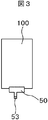
図13は、液晶表示パネルの上に取り付けられるタッチパネル100の平面図である。タッチパネル100は後で説明するように、基板と配線部から構成されている。タッチパネル100には、タッチパネル用フレキシブル配線基板50がとりつけられ、タッチパネル用フレキシブル配線基板50にはタッチパネル制御用IC52、タッチパネル用電子部品群51が搭載されている。タッチパネル用フレキシブル配線基板50にタッチパネル制御用IC52あるいはタッチパネル用電子部品群51が搭載されていることによって、タッチパネルメーカにおいて、タッチパネル100の良、不良を判別することが出来る。
FIG. 13 is a plan view of the
このように、従来方式では、メインフレキシブル配線基板40およびタッチパネル用フレキシブル配線基板50の双方に電子部品、あるいは、制御用ICが搭載されている。フレキシブル配線基板に電子部品あるいは制御用ICを取り付けることは工数が多くかかかるので、液晶表示装置の製造コストを押し上げる。また、フレキシブル配線基板に電子部品あるいは制御用ICを搭載すれば、フレキシブル配線基板のサイズ自体を大きくする必要があり、フレキシブル配線基板の費用が増大する。
As described above, in the conventional method, the electronic component or the control IC is mounted on both the main
本発明の課題は、タッチパネル用フレキシブル配線基板50とメインフレキシブル配線基板40の双方に対して電子部品あるいは制御用IC等を搭載することを回避して、液晶表示装置の製造コストを低減することである。
An object of the present invention is to avoid mounting electronic components or control ICs on both the touch panel
本発明は上記問題点を克服するものであり、具体的な構成は下記のとおりである。 The present invention overcomes the above-described problems, and the specific configuration is as follows.
(1)TFT基板とカラーフィルタ基板を有する液晶表示パネルとバックライトが樹脂モールドに収容され、前記液晶表示パネルの上にはタッチパネルが貼り付けられ、前記タッチパネルにはフロントウインドウが貼り付けられた液晶表示装置であって、前記液晶表示パネルにはメインフレキシブル配線基板が接続し、前記タッチパネルにはタッチパネル用フレキシブル配線基板が接続し、前記タッチパネル用フレキシブル配線基板は前記メインフレキシブル配線基板に接続し、前記TFT基板には、液晶ドライバICが搭載され、前記メインフレキシブル配線基板にはLCD用電子部品群、前記タッチパネルを駆動するためのタッチパネル用制御ICおよびタッチパネル用電子部品群が搭載されていることを特徴とする液晶表示装置。 (1) A liquid crystal display panel having a TFT substrate and a color filter substrate and a backlight are accommodated in a resin mold, a touch panel is pasted on the liquid crystal display panel, and a front window is pasted on the touch panel. In the display device, a main flexible wiring board is connected to the liquid crystal display panel, a touch panel flexible wiring board is connected to the touch panel, the touch panel flexible wiring board is connected to the main flexible wiring board, and A liquid crystal driver IC is mounted on the TFT substrate, and an LCD electronic component group, a touch panel control IC for driving the touch panel, and a touch panel electronic component group are mounted on the main flexible wiring substrate. A liquid crystal display device.
(2)前記タッチパネルは静電容量方式タッチパネルであることを特徴とする(1)に記載の液晶表示装置。 (2) The liquid crystal display device according to (1), wherein the touch panel is a capacitive touch panel.
(3)前記メインフレキシブル配線基板は一部が分岐して、発光ダイオードを搭載した発光ダイオード用フレキシブル配線基板となり、前記樹脂モールドの背面に曲げられ、前記発光ダイオードは、前記バックライトの光源となっていることを特徴とする(1)に記載の液晶表示装置。 (3) The main flexible wiring board is partially branched to become a flexible wiring board for a light emitting diode on which a light emitting diode is mounted, bent to the back surface of the resin mold, and the light emitting diode serves as a light source of the backlight. (1) The liquid crystal display device according to (1).
(4)TFT基板とカラーフィルタ基板を有する液晶表示パネルとバックライトが樹脂モールドに収容され、前記液晶表示パネルの上にはタッチパネルが貼り付けられ、前記タッチパネルにはフロントウインドウが貼り付けられた液晶表示装置であって、前記液晶表示パネルにはメインフレキシブル配線基板が接続し、前記タッチパネルにはタッチパネル用フレキシブル配線基板が接続し、前記タッチパネル用フレキシブル配線基板は前記メインフレキシブル配線基板に接続し、前記TFT基板には、液晶ドライバICおよびタッチパネル用制御ICが搭載され、前記メインフレキシブル配線基板にはLCD用電子部品群、および、タッチパネル用電子部品群が搭載されていることを特徴とする液晶表示装置。 (4) A liquid crystal display panel having a TFT substrate and a color filter substrate and a backlight are accommodated in a resin mold, a touch panel is pasted on the liquid crystal display panel, and a front window is pasted on the touch panel. In the display device, a main flexible wiring board is connected to the liquid crystal display panel, a touch panel flexible wiring board is connected to the touch panel, the touch panel flexible wiring board is connected to the main flexible wiring board, and A liquid crystal driver IC and a touch panel control IC are mounted on the TFT substrate, and an LCD electronic component group and a touch panel electronic component group are mounted on the main flexible wiring substrate. .
(5)前記タッチパネルは静電容量方式タッチパネルであることを特徴とする(5)に記載の液晶表示装置。 (5) The liquid crystal display device according to (5), wherein the touch panel is a capacitive touch panel.
(6)前記メインフレキシブル配線基板は一部が分岐して、発光ダイオードを搭載した発光ダイオード用フレキシブル配線基板となり、前記樹脂モールドの背面に曲げられ、前記発光ダイオードは、前記バックライトの光源となっていることを特徴とする(4)に記載の液晶表示装置。 (6) The main flexible wiring board is partially branched to become a flexible wiring board for a light emitting diode on which a light emitting diode is mounted, bent to the back surface of the resin mold, and the light emitting diode serves as a light source of the backlight. (4) The liquid crystal display device described in (4) above.
本発明によれば、タッチパネル用フレキシブル配線基板からタッチパネル制御用ICおよびタッチパネル用電子部品群を排除するので、タッチパネル用フレキシブル配線基板に電子部品等を搭載するコストを削減することが出来る。また、タッチパネル用フレキシブル配線基板のサイズを小さくすることが出来るので、タッチパネル用フレキシブル配線基板のコストを低減することが出来る。 According to the present invention, since the touch panel control IC and the touch panel electronic component group are excluded from the touch panel flexible wiring board, it is possible to reduce the cost of mounting the electronic components and the like on the touch panel flexible wiring board. Moreover, since the size of the flexible wiring board for touch panels can be reduced, the cost of the flexible wiring board for touch panels can be reduced.
本発明の他の態様によれば、タッチパネル制御用ICを液晶表示パネルに取り付けるので、タッチパネル用フレキシブル配線基板のサイズを小さくすることが出来るとともに、メインフレキシブル配線基板のサイズが増大することを抑えることが出来る。 According to another aspect of the present invention, since the touch panel control IC is attached to the liquid crystal display panel, the size of the flexible wiring board for the touch panel can be reduced and the increase in the size of the main flexible wiring board can be suppressed. I can do it.
実施例にしたがって、本発明の詳細な内容を開示する。 The detailed contents of the present invention will be disclosed according to the embodiments.
図1は本発明の第1の実施例による、液晶表示装置の平面図であり、図2は図1のフロントウインドウ200の下に隠れている液晶表示パネルの平面図であり、図3は、図1のフロントウインドウ200の下に隠れているタッチパネル100の平面図であり、図4はフロントウインドウ200の平面図である。図1は、図2〜図4を組み立てた状態である。
FIG. 1 is a plan view of a liquid crystal display device according to a first embodiment of the present invention, FIG. 2 is a plan view of a liquid crystal display panel hidden under the
図1において、表面にはフロントウインドウ200が配置されている。フロントウインドウ200の下方にタッチパネル100および液晶表示パネルが存在しているが図1ではフロントウインドウ200の下の隠れており、表示されていない。図1において、フロントウインドウ200の短辺側から、下部に配置されたタッチパネル用フレキシブル配線基板50とメインフレキシブル配線基板40が現れている。メインフレキシブル配線基板40およびタッチパネル用フレキシブル配線基板50は、液晶表示装置が携帯電話等のセットに組み込まれるときは、後で説明する樹脂モールドの背面側に折り曲げられることになる。
In FIG. 1, a
図1に示すように、タッチパネル用フレキシブル配線基板50には制御用ICあるいは電子部品群は配置されていない。したがって、タッチパネル用フレキシブル配線基板50は小さくすることが出来る。一方、メインフレキシブル配線基板40にはLCD用電子部品群41の他、タッチパネル用電子部品群51、タッチパネル用制御IC52が配置されている。タッチパネル用フレキシブル配線基板50の端子部53は、メインフレキシブル配線基板の接続部43と接続している。
As shown in FIG. 1, the control IC or the electronic component group is not arranged on the touch-panel
図2は、液晶表示パネルの平面図である。図2において、TFT基板10上にカラーフィルタ基板20が配置されている。TFT基板10とカラーフィルタ基板20の間に図示しない液晶層が挟持されている。TFT基板10とカラーフィルタ基板20とは額縁部に形成された図示しないシール材によって接着している。TFT基板10はカラーフィルタ基板20よりも大きく形成されており、TFT基板10がカラーフィルタ基板20よりも大きくなっている部分には、液晶表示パネルに電源、映像信号、走査信号等を供給するための端子領域が形成されている。
FIG. 2 is a plan view of the liquid crystal display panel. In FIG. 2, a
端子領域には、走査線、映像信号線等を駆動するための液晶ICドライバ30が設置されている。液晶ICドライバ30には走査線駆動回路、映像信号線駆動回路が形成されている。液晶ICドライバ30には、端子領域に接続したメインフレキシブル配線基板40を通して、走査信号、映像信号が供給される。
A liquid
カラーフィルタ基板20の上側には、上偏光板21が貼り付けられている。液晶は偏光光のみを制御することが出来るので、TFT基板10の下側に図示しない下偏光板を接着し、バックライトからの光を直線偏光に偏光する。この直線偏光光が液晶層によって変調を受け、画素毎に透過率が変化することによって画像が形成される。そして、上偏光板21によって再び偏光(検光)することによって人間の目に画像が視認される。液晶表示パネル全体は、枠状の樹脂モールド60内に収容されている。樹脂モールド60内の液晶表示パネルの下側には後で説明するバックライトが収容されている。
An upper
図2に示すメインフレキシブル配線基板には、LCD用電子部品群41の他に、タッチパネル用制御IC52、タッチパネル用電子部品群51が搭載されている。メインフレキシブル配線基板40の端子部43には、タッチパネル用の制御信号等も供給される。メインフレキシブル配線基板40は接続部43を介してタッチパネル用フレキシブル配線基板50と接続し、メインフレキシブル配線基板40からタッチパネルを制御する信号が送られる。
In addition to the LCD
本実施例においては、メインフレキシブル配線基板40に搭載される電子部品は従来例よりも多くなるが、タッチパネル用フレキシブル配線基板50には電子部品は搭載されない。電子部品を搭載するコストは、フレキシブル配線基板に搭載する電子部品の数よりも、電子部品を搭載するフレキシブル配線基板の数が大きく影響する。したがって、本発明のように、メインフレキシブル配線基板40に電子部品を全て搭載することによって液晶表示装置の製造コストを低減することが出来る。なお、メインフレキシブル配線基板40の裏側には、後で説明するバックライトに使用される発光ダイオードが搭載されている。
In this embodiment, more electronic components are mounted on the main
図3は図2で説明した液晶表示パネルの上に貼り付けられるタッチパネル100の平面図である。タッチパネル100は液晶表示パネルのカラーフィルタ基板20よりもやや大きく形成されている。図3において、タッチパネル100に電源や信号を供給するタッチパネル用フレキシブル配線基板50がタッチパネル100の端部に取り付けられている。
FIG. 3 is a plan view of the
タッチパネル用フレキシブル配線基板50には、電子部品群およびタッチパネル用制御IC等は搭載されておらず、配線のみが形成されている。したがって、タッチパネル用フレキシブル配線基板は小さく形成され、また、電子部品等の搭載作業が無いので、タッチパネル用フレキシブル配線基板の製造コストは非常に小さく抑えることが出来る。タッチパネル用フレキシブル配線基板50は端子部53において、メインフレキシブル配線基板40と接続される。
The touch panel
図3に示すタッチパネル100は静電容量式のタッチパネル100である。静電容量式のタッチパネル100の断面模式図を図5に示す。図5において、タッチパネル基板101上には下部配線102が形成され、下部配線102の上には絶縁層103が形成され、絶縁層103の上には上部配線104が形成され、さらに上部配線104を覆って保護膜105が形成されている。
A
タッチパネル基板101は一般にはガラスで形成されるが、透明であり、ITOのアニール等の温度に耐えることが出来ればプラスチック基板でもよい。透明樹脂としては、例えば、アクリル、ポリカーボネイト等を使用することが出来る。
The
タッチパネル基板101の表面には下部配線102が形成されている。下部配線102は透明導電膜であるITOによって形成される。ITOはスパッタリングによって被着された後、ストライプ状にパターニングされ、図6のx方向に延在し、y方向、すなわち、紙面垂直方向に配列している。
A
下部配線102を覆って絶縁層103がSiO2膜あるいはSiN膜によって形成される。絶縁層103の上には上部配線104が形成される。上部配線104も透明導電膜であるITOによって形成される。ITOはスパッタリングによって被着された後、ストライプ状にパターニングされ、図5のy方向、すなわち、紙面垂直方向に延在し、x方向に配列している。
An insulating
図5において、下部配線102と上部配線104は直角方向に配列しており、平面でみると、下部配線102と上部配線104で正方形の辺を形成している。一方、下部配線102と上部配線104をタッチパネル100の外形に対して斜め方向のストライプにパンターニングすることも出来る。この場合は、平面でみると下部配線102と上部配線104で菱形の辺を形成することになる。
In FIG. 5, the
上部配線104はSiO2膜あるいはSiN膜で形成された保護膜105によって被覆され、保護されている。本実施例においては、タッチパネル100の上にはフロントウインドウ200が配置されるが、フロントウインドウ200が無い場合は、タッチパネル100を専用ペンあるいは指で触ることになるので、配線がダメージを受けることを保護膜105によって防止する。
The
上部電極の上を保護膜105およびフロントウインドウ200の上から専用ペンあるいは指で接触することによって、上部配線104と専用ペンあるいは指との間に静電容量が形成されて、接触された部分の上部電極と下部電極の間に形成されていた電荷が移動することになり、位置を検出することが出来る。
By contacting the upper electrode with the dedicated pen or the finger from above the
図5において、上部配線104は絶縁層103に形成された図示しないスルーホールを介してタッチパネル100の端子部と導通している。したがって、タッチパネル100の端子では、上部配線104と下部配線102の両方に信号および電流を供給することが出来るので、接続されるタッチパネル用フレキシブル配線基板50は一枚でよい。
In FIG. 5, the
タッチパネル用フレキシブル配線基板50はタッチパネル100の端子領域において、異方性導電フィルム106を用いて接続されている。本発明では、タッチパネル用制御IC、タッチパネル用電子部品群等はタッチパネル用フレキシブル配線基板に搭載されるので、端子部の抵抗を小さくするために半田によって接続する場合もある。
The touch panel
タッチパネル100をタッチパネルメーカが出荷する際、タッチパネル100の動作を検査する必要がある。従来は、タッチパネル100に取り付けられたタッチパネル用フレキシブル配線基板50にタッチパネル用制御IC、および、タッチパネル用電子部品群が搭載されているので、タッチパネル単体で検査することが出来た。本発明に使用されるタッチパネル用フレキシブル配線基板には配線のみしか形成されていないので、タッチパネル単体での検査は出来ない。
When the touch panel manufacturer ships the
したがって、タッチパネルの検査は、メインフレキシブル配線基板40が搭載された液晶表示パネルと組み合わせて行うことになる。あるいは、タッチパネルの検査装置に、メインフレキシブル配線基板に搭載されたタッチパネル用制御ICおよびタッチパネル用電子部品群の機能を組み込んで検査をすることになる。
Therefore, the touch panel inspection is performed in combination with the liquid crystal display panel on which the main
タッチパネル100は液晶表示パネルのカラーフィルタ基板20に粘着材によって取り付けられる。粘着材は、熱可塑性の樹脂、例えば、アクリル系の透明粘着材が使用される。完成後、気泡、異物等の不良が見つかった場合に、フロントウインドウ200、タッチパネル100、液晶表示パネルを引き剥がしてリペアをするためである。
The
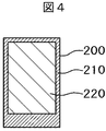
図4はタッチパネル100に貼り付けられるフロントウインドウ200の平面図である。フロントウインドウ200は一般にはガラスが用いられ、厚さは0.5mm程度である。フロントウインドウ200の材料にはアクリル樹脂、ポリカーボネイト樹脂等の透明プラスチックを用いることも出来る。
FIG. 4 is a plan view of the
フロントウインドウ200の外形は液晶表示パネルおよび樹脂モールド60よりも大きく、液晶表示パネル等全体を保護している。フロントウインドウ200の周辺には印刷によって黒色の枠部210が形成されている。黒色の枠部210の下には、電子部品、樹脂モールド等が存在することになる。枠部210には必要に応じてロゴマーク等が印刷によって形成される。枠で囲まれた内部が表示領域220である。
The outer shape of the
フロントウインドウ200は、粘着材によってタッチパネル100に貼り付けられる。粘着材は熱可塑性の透明なアクリル樹脂等を用いることが出来る。完成後、気泡、異物等の不良が見つかった場合に、フロントウインドウ200、タッチパネル100、液晶表示パネルを引き剥がしてリペアをするためである。
The
図6は図1に示す液晶表示装置の断面図である。但し図6では、LCD用電子部品群41、タッチパネル用電子部品群51、タッチパネル用制御IC52等はフロントウインドウ200の下に配置されている。カラーフィルタ基板20に接着した上偏光板21に第1粘着材110を介してタッチパネル100が接着している。タッチパネル100の構造は先に説明したとおりである。また図1に示すメインフレキシブル配線基板は樹脂モールド60の背面に折り曲げられている。
FIG. 6 is a cross-sectional view of the liquid crystal display device shown in FIG. However, in FIG. 6, the LCD
タッチパネル100の上にはフロントウインドウ200が第2粘着材210を介して接着している。フロントウインドウ200の外形は大きく、タッチパネル用フレキシブル配線基板50およびメインフレキシブル配線基板40も覆っている。本実施例では、第1粘着材110も第2粘着材210も透明なアクリル系の粘着材が使用される。
A
図6において、液晶表示パネルは樹脂モールド60に載置されている。図6において、液晶表示パネルの下偏光板11は樹脂モールド60内に収容され、下偏光板11の背面にはバックライトが配置されている。バックライトは次のような構成となっている。
In FIG. 6, the liquid crystal display panel is placed on a
端部が発光ダイオード70と対向した導光板62が配置されている。導光板62の役割は側面から入射する発光ダイオード70からの光を液晶表示パネル側に向けることである。発光ダイオード70はサイズが大きいので、液晶表示装置全体の厚さを小さくするために、導光板62は発光ダイオード70と対向する部分において、厚さを大きくし、後で述べる光学シートと重なる部分において、厚さを小さくしている。
A
図6において、導光板62の下側には反射シート61が配置されている。導光板62から下側に向かう光を反射して液晶表示パネル側に向かわせるためである。一方、導光板62の上側には下拡散シート、下プリズムシート、上プリズムシート、上拡散シート等からなる光学シート群63が配置されている。プリズムシートは、バックライトからの光の利用効率を上げるためであり、拡散シートは、輝度むらやモアレの発生を防止するためである。
In FIG. 6, a
図6において、これらの光学シート群63は導光板62の上に重ねられる。光学シート群63の一番上の、例えば、上拡散シートと液晶表示パネルの下偏光板11との間には50μm程度の間隔が空けられている。下偏光板11と上拡散シート66が擦れて傷が発生することを防止するためである。
In FIG. 6, these
タッチパネル100にはタッチパネル用フレキシブル配線基板50が接続している。タッチパネル用フレキシブル配線基板50にはタッチパネル用制御IC、タッチパネル用電子部品群等は搭載されておらず、配線のみが形成され、液晶表示パネルに接続しているメインフレキシブル配線基板と接続している。
A touch panel
液晶表示パネルには液晶ドライバIC30が搭載されている。メインフレキシブル配線基板40は、バックライトの背面に折り曲げられ、メインフレキシブル配線基板40に搭載された発光ダイオード70がバックライトの光源となる。メインフレキシブル配線基板40を背面に曲げた際、樹脂モールド60に形成された凹部に発光ダイオード70を収容する。そして発光ダイオード70は図6に示すように、導光板62の端部と対向して配置され、バックライトの光源となる。なお、発光ダイオード70には本実施例においては、白色発光ダイオードが使用される。
A liquid
メインフレキシブル配線基板40には、液晶表示パネルを制御するためのLCD用電子部品群41の他に、タッチパネルを制御するためのタッチパネル用制御IC52、タッチパネル用電子部品群51等が搭載されている。タッチパネル100は、メインフレキシブル配線基板40に配置されたタッチパネル用制御IC52等によって制御される。
In addition to the LCD
本実施例では、タッチパネル用フレキシブル配線基板50には、タッチパネル用制御IC、タッチパネル用電子部品群等は搭載されていないので、タッチパネル用フレキシブル配線基板50にこれらの部品を搭載する工数を省略でき、また、タッチパネル用フレキシブル配線基板50の大きさを小さくすることが出来る。一方、メインフレキシブル配線基板40にタッチパネル用制御IC52、タッチパネル用電子部品群61を搭載するが、これらの部品を搭載するための工数の増加は僅かである。したがって、本実施例による液晶表示装置の製造コストは大幅に低減することが出来る。
In the present embodiment, since the touch panel
図7は本発明の第2の実施例による液晶表示装置の平面図である。図7は、実施例1の液晶表示装置の平面図である図1とは、液晶表示パネルに接続するメインフレキシブル配線基板40が異なっている。図7において、タッチパネル100に接続するタッチパネル用フレキシブル配線基板50には、タッチパネル用制御IC、タッチパネル用電子部品群等は搭載されておらず、配線のみが形成されている点は、実施例1と同様である。また、本実施例に使用されるタッチパネル100、フロントウインドウ200は実施例1で説明したものと同様である。
FIG. 7 is a plan view of a liquid crystal display device according to a second embodiment of the present invention. FIG. 7 is different from FIG. 1, which is a plan view of the liquid crystal display device according to the first embodiment, in the main
図7において、タッチパネル用フレキシブル配線基板50の端子部53は、メインフレキシブル配線基板40の接続部43と接続している。メインフレキシブル配線基板40には、LCD用電子部品群41の他にタッチパネル用電子部品群51が搭載されている。しかし、メインフレキシブル配線基板40にはタッチパネル用制御IC52は搭載されていない。これが実施例1と異なる点である。
In FIG. 7, the
図8は、図7の液晶表示装置に使用される液晶表示パネルの平面図である。図8において、TFT基板10に形成された端子領域には、液晶ドライバIC30の他に、タッチパネル用制御IC52が搭載されている。液晶ドライバIC30およびタッチパネル用制御IC52は、チップの状態でTFT基板10に直接搭載されている。
FIG. 8 is a plan view of a liquid crystal display panel used in the liquid crystal display device of FIG. In FIG. 8, in addition to the liquid
本実施例においては、タッチパネル100は、液晶表示パネルに搭載されたタッチパネル用制御IC52によって、メインフレキシブル配線基板40、および、タッチパネル用フレキシブル配線基板50を介して制御される。ただし、タッチパネル用電子部品群51はメインフレキシブル配線基板40に搭載されているので、タッチパネル100は、メインフレキシブル配線基板40のタッチパネル用電子部品群51と液晶表示パネル上のタッチパネル用制御IC52が協働して制御する。
In this embodiment, the
この場合、TFT基板10におけるメインフレキシブル配線基板40の端子部から、タッチパネル用制御IC52までの配線抵抗が大きいと、タッチパネル100の応答速度の遅れ等が発生する。メインフレキシブル配線基板40の端子部からタッチパネル用制御IC52までの配線は、TFT基板10の映像信号線の形成と同時に行うことが出来る。映像信号線は、AlまたはAl合金を使用するので、配線抵抗は小さくすることが出来る。また、端子部あるいは、タッチパネル用制御IC52との接続部以外の配線は、無機パッシベーション膜、および、有機パッシベーション膜等で覆うことが出来るので、配線の信頼性も確保することが出来る。
In this case, if the wiring resistance from the terminal portion of the main
本実施例では、タッチパネル用制御IC52をチップの状態で、TFT基板10に搭載することが出来るので、フレキシブル配線基板にタッチパネル用制御IC52を搭載する場合に比較して、タッチパネル用制御IC52の占める面積を小さくすることが出来る。また、本実施例では、タッチパネル用制御IC52は液晶表示パネルに搭載されているので、実施例1の場合に比較してメインフレキシブル配線基板40の大きさを小さくすることが出来る。したがって、本実施例によれば、液晶表示装置全体として外形を小さくすることが出来る。また、タッチパネル用フレキシブル配線基板50に電子部品等を搭載しないことによる液晶表示装置の製造コストの削減が出来ることは実施例1と同様である。
In this embodiment, since the touch
図9は、本発明の第3の実施例に使用されるメインフレキシブル配線基板40の斜視図である。本実施例における液晶表示装置の平面図は、実施例1における図1と同様であり、また、液晶表示パネルの平面図は実施例1の図2と同様である。また、本実施例に使用されるタッチパネル100、フロントウインドウ200は実施例1で説明したものと同様である。
FIG. 9 is a perspective view of the main
図9のメインフレキシブル配線基板40は、一部が分岐して発光ダイオード用フレキシブル配線基板45となっている。発光ダイオード用フレキシブル配線基板45は背面に曲げられて、発光ダイオード70が図示しないバックライトの導光板の側面に配置されることになる。実施例1あるいは、実施例2においては、メインフレキシブル配線基板40全体が樹脂モールドの後方に曲げられているが、本実施例では、分岐した発光ダイオード用フレキシブル配線基板45のみが、樹脂モールド60の背面に曲げられる。
The main
メインフレキシブル配線基板40には、LCD用電子部品群41の他に、タッチパネル用制御IC52あるいはタッチパネル用電子部品群51が搭載されている点は、実施例1と同様である。タッチパネル用制御IC52をメインフレキシブル配線基板40に搭載せずに、実施例2のように、TFT基板10の端子領域に配置しても良い。
The main
図10は、本実施例における液晶表示装置の断面図である。図10において、メインフレキシブル配線基板40の他は、実施例1の図6と同様である。すなわち、タッチパネル100を制御するためのタッチパネル用制御IC52およびタッチパネル用電子部品群51はメインフレキシブル配線基板40に搭載されている。図10において、メインフレキシブル配線基板40から分岐した発光ダイオード用フレキシブル配線基板45が樹脂モールド60の背面に曲げられて、発光ダイオード70を導光板62の側面に配置するようにしている。
FIG. 10 is a cross-sectional view of the liquid crystal display device in this example. 10 is the same as FIG. 6 of the first embodiment except for the main
本実施例においても、実施例1と同様な効果を得ることが出来る。すなわち、種々異なるメインフレキシブル配線基板40を使用しても本発明を適用することが出来る。また、図9、図10等では、メインフレキシブル配線基板40にタッチパネル用制御IC52とタッチパネル用電子部品群51を搭載しているが、実施例2のように、図9あるいは図10において、タッチパネル用制御IC52をメインフレキシブル配線基板40に配置せずに、TFT基板10の端子領域に配置することも出来る。
Also in this embodiment, the same effect as that of Embodiment 1 can be obtained. That is, the present invention can be applied even when different main
10…TFT基板、11…下偏光板、 20…カラーフィルタ基板、 21…上偏光板、 30…液晶ドライバIC、 40…メインフレキシブル配線基板、 41…LCD用電子部品、 43…タッチパネル用フレキシブル配線基板との接続部、 44…メインフレキシブル配線基板端子部、 45…発光ダイオード用フレキシブル配線基板、 50…タッチパネル用フレキシブル配線基板、 51…タッチパネル用電子部品、 52…タッチパネル用制御IC、 53…タッチパネル用フレキシブル配線基板端子部、 60…樹脂モールド、 61…反射シート、 62…導光板、 63…光学シート群、 70…発光ダイオード、 100…タッチパネル、 101…タッチパネル基板、 102…下配線、 103…絶縁層、 104…上配線、 105…保護膜、 106…異方性導電フィルム、 110…第1粘着材、 200…フロントウインドウ、 210…第2粘着材、 220…フロントウインドウの枠部、 230…表示領域。
DESCRIPTION OF
Claims (6)
前記液晶表示パネルにはメインフレキシブル配線基板が接続し、前記タッチパネルにはタッチパネル用フレキシブル配線基板が接続し、
前記タッチパネル用フレキシブル配線基板は前記メインフレキシブル配線基板に接続し、
前記タッチパネル用フレキシブル配線基板は前記メインフレキシブル配線基板とは別個の部品であり、
前記TFT基板には、液晶ドライバICが搭載され、
前記メインフレキシブル配線基板にはLCD用電子部品群、前記タッチパネルを駆動するためのタッチパネル用制御ICおよびタッチパネル用電子部品群が搭載されており、
前記フロントウインドウは、前記メインフレキシブル配線基板及び前記タッチパネル用フレキシブル配線基板を覆っていることを特徴とする液晶表示装置。 A liquid crystal display device having a TFT substrate and a color filter substrate and a backlight housed in a resin mold, a touch panel attached to the liquid crystal display panel, and a front window attached to the touch panel. There,
A main flexible wiring board is connected to the liquid crystal display panel, a flexible wiring board for a touch panel is connected to the touch panel,
The touch panel flexible wiring board is connected to the main flexible wiring board,
The touch panel flexible wiring board is a separate component from the main flexible wiring board,
A liquid crystal driver IC is mounted on the TFT substrate,
The main flexible wiring board is mounted with an LCD electronic component group, a touch panel control IC for driving the touch panel, and a touch panel electronic component group,
The liquid crystal display device , wherein the front window covers the main flexible wiring board and the flexible wiring board for touch panel .
前記液晶表示パネルにはメインフレキシブル配線基板が接続し、前記タッチパネルにはタッチパネル用フレキシブル配線基板が接続し、
前記タッチパネル用フレキシブル配線基板は前記メインフレキシブル配線基板に接続し、
前記タッチパネル用フレキシブル配線基板は前記メインフレキシブル配線基板とは別個の部品であり、
前記TFT基板には、液晶ドライバICおよびタッチパネル用制御ICが搭載され、
前記メインフレキシブル配線基板にはLCD用電子部品群、および、タッチパネル用電子部品群が搭載され、
前記フロントウインドウは、前記メインフレキシブル配線基板及び前記タッチパネル用フレキシブル配線基板を覆っていることを特徴とする液晶表示装置。 A liquid crystal display device having a TFT substrate and a color filter substrate and a backlight housed in a resin mold, a touch panel attached to the liquid crystal display panel, and a front window attached to the touch panel. There,
A main flexible wiring board is connected to the liquid crystal display panel, a flexible wiring board for a touch panel is connected to the touch panel,
The touch panel flexible wiring board is connected to the main flexible wiring board,
The touch panel flexible wiring board is a separate component from the main flexible wiring board,
The TFT substrate is equipped with a liquid crystal driver IC and a touch panel control IC,
The main flexible wiring board is mounted with an LCD electronic component group and a touch panel electronic component group,
The liquid crystal display device , wherein the front window covers the main flexible wiring board and the flexible wiring board for touch panel .
Priority Applications (3)
| Application Number | Priority Date | Filing Date | Title |
|---|---|---|---|
| JP2009144126A JP5584433B2 (en) | 2009-06-17 | 2009-06-17 | Liquid crystal display |
| US12/814,583 US9323289B2 (en) | 2009-06-17 | 2010-06-14 | Liquid crystal display device with touch panel |
| US15/073,879 US9436340B2 (en) | 2009-06-17 | 2016-03-18 | Liquid crystal display device with touch panel |
Applications Claiming Priority (1)
| Application Number | Priority Date | Filing Date | Title |
|---|---|---|---|
| JP2009144126A JP5584433B2 (en) | 2009-06-17 | 2009-06-17 | Liquid crystal display |
Publications (2)
| Publication Number | Publication Date |
|---|---|
| JP2011002553A JP2011002553A (en) | 2011-01-06 |
| JP5584433B2 true JP5584433B2 (en) | 2014-09-03 |
Family
ID=43353880
Family Applications (1)
| Application Number | Title | Priority Date | Filing Date |
|---|---|---|---|
| JP2009144126A Active JP5584433B2 (en) | 2009-06-17 | 2009-06-17 | Liquid crystal display |
Country Status (2)
| Country | Link |
|---|---|
| US (2) | US9323289B2 (en) |
| JP (1) | JP5584433B2 (en) |
Families Citing this family (30)
| Publication number | Priority date | Publication date | Assignee | Title |
|---|---|---|---|---|
| WO2012030183A2 (en) * | 2010-09-01 | 2012-03-08 | Lee Sung Ho | Capacitive touch detection apparatus using level shift, detection method using level shift, and display device having the detection apparatus built therein |
| JP5804323B2 (en) | 2011-01-07 | 2015-11-04 | 株式会社Gsユアサ | Power storage element and power storage device |
| TWI448775B (en) * | 2011-01-26 | 2014-08-11 | Young Lighting Technology Corp | Display device |
| TWI478125B (en) * | 2011-04-01 | 2015-03-21 | E Ink Holdings Inc | A display with a touch panel |
| WO2012157458A1 (en) * | 2011-05-13 | 2012-11-22 | シャープ株式会社 | Display device |
| JP5687570B2 (en) * | 2011-06-10 | 2015-03-18 | 株式会社ジャパンディスプレイ | Display device |
| JP5990948B2 (en) | 2011-06-22 | 2016-09-14 | セイコーエプソン株式会社 | projector |
| US20130113712A1 (en) * | 2011-11-04 | 2013-05-09 | Nokia Corporation | User Interface Panel Connection |
| JP2013160942A (en) * | 2012-02-06 | 2013-08-19 | Sony Corp | Semiconductor device, method of manufacturing the same, and electronic apparatus |
| US9961814B2 (en) * | 2012-11-30 | 2018-05-01 | Dell Products, Lp | Touch panel device and method for assembly of a touch panel display |
| KR102079095B1 (en) * | 2013-04-11 | 2020-02-20 | 삼성디스플레이 주식회사 | Display apparatus |
| JP6240891B2 (en) * | 2013-04-12 | 2017-12-06 | パナソニックIpマネジメント株式会社 | refrigerator |
| JP6201142B2 (en) * | 2013-04-12 | 2017-09-27 | パナソニックIpマネジメント株式会社 | refrigerator |
| JP6240889B2 (en) * | 2013-04-12 | 2017-12-06 | パナソニックIpマネジメント株式会社 | refrigerator |
| JP6240890B2 (en) * | 2013-04-12 | 2017-12-06 | パナソニックIpマネジメント株式会社 | refrigerator |
| KR102107564B1 (en) | 2013-11-06 | 2020-05-08 | 삼성디스플레이 주식회사 | Liquid crystal device |
| TWI517115B (en) * | 2014-10-03 | 2016-01-11 | 友達光電股份有限公司 | Display module with curved surface |
| KR101677334B1 (en) | 2014-10-24 | 2016-11-17 | 엘지전자 주식회사 | Refrigerator door |
| KR102023152B1 (en) | 2014-11-07 | 2019-09-20 | 엘지전자 주식회사 | Refrigerator |
| CN105588400B (en) * | 2014-11-07 | 2018-04-13 | Lg电子株式会社 | Refrigerator and controlling method for refrigerator |
| KR101659180B1 (en) | 2014-12-22 | 2016-09-22 | 엘지전자 주식회사 | Tuch sensor assembly and refrigerator door with Tuch sensor assembly |
| KR101659181B1 (en) | 2014-12-22 | 2016-09-30 | 엘지전자 주식회사 | Tuch sensor assembly and refrigerator door with Tuch sensor assembly |
| KR101668922B1 (en) | 2014-12-24 | 2016-10-24 | 엘지전자 주식회사 | Home appliance display assembly and manufacture method thereof |
| KR101659184B1 (en) | 2014-12-24 | 2016-09-22 | 엘지전자 주식회사 | Tuch sensor assembly and manufacture method of tuch sensor assembly |
| KR101668921B1 (en) | 2014-12-24 | 2016-10-24 | 엘지전자 주식회사 | Tuch sensor assembly and refrigerator door with Tuch sensor assembly |
| KR102297494B1 (en) * | 2015-01-28 | 2021-09-03 | 삼성디스플레이 주식회사 | Display device |
| KR102369089B1 (en) * | 2015-04-17 | 2022-03-02 | 삼성디스플레이 주식회사 | Flexible display device |
| JP6531033B2 (en) * | 2015-11-24 | 2019-06-12 | 株式会社ジャパンディスプレイ | Display device |
| KR101736608B1 (en) | 2015-11-27 | 2017-05-16 | 엘지전자 주식회사 | Refrigerator |
| JP6620025B2 (en) * | 2016-01-19 | 2019-12-11 | 株式会社ジャパンディスプレイ | Display device with sensor |
Family Cites Families (24)
| Publication number | Priority date | Publication date | Assignee | Title |
|---|---|---|---|---|
| US6215476B1 (en) * | 1997-10-10 | 2001-04-10 | Apple Computer, Inc. | Flat panel display with integrated electromagnetic pen digitizer |
| JP2002041231A (en) * | 2000-05-17 | 2002-02-08 | Hitachi Ltd | Display unit of screen entry type |
| US6587097B1 (en) * | 2000-11-28 | 2003-07-01 | 3M Innovative Properties Co. | Display system |
| JP4357868B2 (en) * | 2003-04-25 | 2009-11-04 | シャープ株式会社 | Display device |
| JP2005158008A (en) * | 2003-11-06 | 2005-06-16 | Matsushita Electric Ind Co Ltd | Touch panel and liquid crystal display device with touch panel using the same |
| JP2008069333A (en) | 2006-09-14 | 2008-03-27 | Masateru Kobayashi | Method of controlling cissing and pinhole of two-pack epoxy |
| JP5413937B2 (en) | 2006-09-28 | 2014-02-12 | 株式会社ジャパンディスプレイ | Electro-optical device and electronic apparatus |
| JP2008130653A (en) * | 2006-11-17 | 2008-06-05 | Epson Imaging Devices Corp | Electronic component, electrooptical device, and electronic equipment |
| KR101330697B1 (en) | 2006-12-21 | 2013-11-18 | 삼성디스플레이 주식회사 | Display device |
| JP5010925B2 (en) | 2007-01-12 | 2012-08-29 | 株式会社ジャパンディスプレイイースト | LCD module |
| JP4809783B2 (en) * | 2007-01-26 | 2011-11-09 | 株式会社 日立ディスプレイズ | Display module with touch panel |
| JP2009069333A (en) | 2007-09-12 | 2009-04-02 | Epson Imaging Devices Corp | Electro-optical apparatus and electronic apparatus |
| JP5134327B2 (en) | 2007-09-26 | 2013-01-30 | 株式会社ジャパンディスプレイイースト | Display device |
| JP4605201B2 (en) | 2007-09-27 | 2011-01-05 | ソニー株式会社 | Communication device |
| JP2009086077A (en) * | 2007-09-28 | 2009-04-23 | Hitachi Displays Ltd | Liquid crystal display device equipped with touch panel and manufacturing method thereof |
| JP2009116090A (en) * | 2007-11-07 | 2009-05-28 | Hitachi Displays Ltd | Liquid crystal display device |
| JP2009116204A (en) | 2007-11-09 | 2009-05-28 | Hitachi Displays Ltd | Liquid crystal display device |
| KR101427586B1 (en) * | 2007-12-26 | 2014-08-07 | 삼성디스플레이 주식회사 | Display device and driving method thereof |
| TWI380071B (en) * | 2008-02-04 | 2012-12-21 | Au Optronics Corp | Sensing structure of a liquid crystal display |
| KR101354274B1 (en) * | 2008-02-21 | 2014-01-24 | 주식회사 옵솔 | Liquid Crystal Display Device integrated touch panel |
| TWI365013B (en) * | 2008-05-23 | 2012-05-21 | Au Optronics Corp | Flat panel display |
| US20100117809A1 (en) * | 2008-11-11 | 2010-05-13 | Motorola Inc. | Display module with piezoelectric haptics |
| WO2010095189A1 (en) * | 2009-02-20 | 2010-08-26 | シャープ株式会社 | Display device with touch panel |
| JP5318717B2 (en) * | 2009-09-29 | 2013-10-16 | 株式会社ジャパンディスプレイ | Liquid crystal display |
-
2009
- 2009-06-17 JP JP2009144126A patent/JP5584433B2/en active Active
-
2010
- 2010-06-14 US US12/814,583 patent/US9323289B2/en active Active
-
2016
- 2016-03-18 US US15/073,879 patent/US9436340B2/en active Active
Also Published As
| Publication number | Publication date |
|---|---|
| US9436340B2 (en) | 2016-09-06 |
| US20100321318A1 (en) | 2010-12-23 |
| US20160216805A1 (en) | 2016-07-28 |
| US9323289B2 (en) | 2016-04-26 |
| JP2011002553A (en) | 2011-01-06 |
Similar Documents
| Publication | Publication Date | Title |
|---|---|---|
| JP5584433B2 (en) | Liquid crystal display | |
| JP5308749B2 (en) | Liquid crystal display | |
| US11150756B2 (en) | Liquid crystal display device | |
| JP5226630B2 (en) | Liquid crystal display | |
| JP2003288164A (en) | Producing method of liquid crystal display device integrated with film-type touch panel | |
| JP5331437B2 (en) | Liquid crystal display | |
| JP2012145779A (en) | Liquid crystal display device | |
| JP2010224081A (en) | Display device | |
| JP2008009225A (en) | Display device and its manufacturing method | |
| KR20150001155A (en) | Liquid crystal display device | |
| JP5385475B2 (en) | Mobile phone equipment | |
| JP2008026584A (en) | Electro-optical device and electronic apparatus | |
| JP5714678B2 (en) | Mobile phone equipment | |
| US10802326B2 (en) | Terminal device including display module |
Legal Events
| Date | Code | Title | Description |
|---|---|---|---|
| A711 | Notification of change in applicant |
Free format text: JAPANESE INTERMEDIATE CODE: A712 Effective date: 20110218 |
|
| RD03 | Notification of appointment of power of attorney |
Free format text: JAPANESE INTERMEDIATE CODE: A7423 Effective date: 20110218 |
|
| A621 | Written request for application examination |
Free format text: JAPANESE INTERMEDIATE CODE: A621 Effective date: 20120528 |
|
| A977 | Report on retrieval |
Free format text: JAPANESE INTERMEDIATE CODE: A971007 Effective date: 20121220 |
|
| A131 | Notification of reasons for refusal |
Free format text: JAPANESE INTERMEDIATE CODE: A131 Effective date: 20130129 |
|
| A521 | Request for written amendment filed |
Free format text: JAPANESE INTERMEDIATE CODE: A523 Effective date: 20130318 |
|
| A02 | Decision of refusal |
Free format text: JAPANESE INTERMEDIATE CODE: A02 Effective date: 20130611 |
|
| A521 | Request for written amendment filed |
Free format text: JAPANESE INTERMEDIATE CODE: A523 Effective date: 20130905 |
|
| A911 | Transfer to examiner for re-examination before appeal (zenchi) |
Free format text: JAPANESE INTERMEDIATE CODE: A911 Effective date: 20130912 |
|
| A912 | Re-examination (zenchi) completed and case transferred to appeal board |
Free format text: JAPANESE INTERMEDIATE CODE: A912 Effective date: 20131011 |
|
| A61 | First payment of annual fees (during grant procedure) |
Free format text: JAPANESE INTERMEDIATE CODE: A61 Effective date: 20140718 |
|
| R150 | Certificate of patent or registration of utility model |
Ref document number: 5584433 Country of ref document: JP Free format text: JAPANESE INTERMEDIATE CODE: R150 |
|
| R250 | Receipt of annual fees |
Free format text: JAPANESE INTERMEDIATE CODE: R250 |
|
| R250 | Receipt of annual fees |
Free format text: JAPANESE INTERMEDIATE CODE: R250 |
|
| R250 | Receipt of annual fees |
Free format text: JAPANESE INTERMEDIATE CODE: R250 |
|
| R250 | Receipt of annual fees |
Free format text: JAPANESE INTERMEDIATE CODE: R250 |
|
| R250 | Receipt of annual fees |
Free format text: JAPANESE INTERMEDIATE CODE: R250 |
|
| R250 | Receipt of annual fees |
Free format text: JAPANESE INTERMEDIATE CODE: R250 |
|
| R250 | Receipt of annual fees |
Free format text: JAPANESE INTERMEDIATE CODE: R250 |
|
| S111 | Request for change of ownership or part of ownership |
Free format text: JAPANESE INTERMEDIATE CODE: R313117 |
|
| R350 | Written notification of registration of transfer |
Free format text: JAPANESE INTERMEDIATE CODE: R350 |