JP4587055B2 - Assembled battery - Google Patents
Assembled battery Download PDFInfo
- Publication number
- JP4587055B2 JP4587055B2 JP2008056699A JP2008056699A JP4587055B2 JP 4587055 B2 JP4587055 B2 JP 4587055B2 JP 2008056699 A JP2008056699 A JP 2008056699A JP 2008056699 A JP2008056699 A JP 2008056699A JP 4587055 B2 JP4587055 B2 JP 4587055B2
- Authority
- JP
- Japan
- Prior art keywords
- side wall
- gap filling
- electrode body
- assembled battery
- flow channel
- Prior art date
- Legal status (The legal status is an assumption and is not a legal conclusion. Google has not performed a legal analysis and makes no representation as to the accuracy of the status listed.)
- Active
Links
- 239000002826 coolant Substances 0.000 claims description 13
- 238000004804 winding Methods 0.000 claims description 8
- 238000001816 cooling Methods 0.000 description 16
- 239000000463 material Substances 0.000 description 15
- 230000017525 heat dissipation Effects 0.000 description 14
- HBBGRARXTFLTSG-UHFFFAOYSA-N Lithium ion Chemical compound [Li+] HBBGRARXTFLTSG-UHFFFAOYSA-N 0.000 description 10
- 229910001416 lithium ion Inorganic materials 0.000 description 10
- 239000003792 electrolyte Substances 0.000 description 7
- 230000000694 effects Effects 0.000 description 5
- 238000002474 experimental method Methods 0.000 description 5
- 239000000470 constituent Substances 0.000 description 4
- 238000007599 discharging Methods 0.000 description 4
- 229910052744 lithium Inorganic materials 0.000 description 4
- 229910052751 metal Inorganic materials 0.000 description 4
- 239000002184 metal Substances 0.000 description 4
- 239000007773 negative electrode material Substances 0.000 description 4
- -1 polypropylene Polymers 0.000 description 4
- 239000007774 positive electrode material Substances 0.000 description 4
- 230000005855 radiation Effects 0.000 description 4
- 230000000452 restraining effect Effects 0.000 description 4
- WHXSMMKQMYFTQS-UHFFFAOYSA-N Lithium Chemical compound [Li] WHXSMMKQMYFTQS-UHFFFAOYSA-N 0.000 description 3
- 239000008151 electrolyte solution Substances 0.000 description 3
- 239000011888 foil Substances 0.000 description 3
- 229920003002 synthetic resin Polymers 0.000 description 3
- 239000000057 synthetic resin Substances 0.000 description 3
- OKTJSMMVPCPJKN-UHFFFAOYSA-N Carbon Chemical compound [C] OKTJSMMVPCPJKN-UHFFFAOYSA-N 0.000 description 2
- 229910013870 LiPF 6 Inorganic materials 0.000 description 2
- PXHVJJICTQNCMI-UHFFFAOYSA-N Nickel Chemical compound [Ni] PXHVJJICTQNCMI-UHFFFAOYSA-N 0.000 description 2
- 239000004743 Polypropylene Substances 0.000 description 2
- 230000032683 aging Effects 0.000 description 2
- 229910052782 aluminium Inorganic materials 0.000 description 2
- XAGFODPZIPBFFR-UHFFFAOYSA-N aluminium Chemical compound [Al] XAGFODPZIPBFFR-UHFFFAOYSA-N 0.000 description 2
- 239000003990 capacitor Substances 0.000 description 2
- 238000007796 conventional method Methods 0.000 description 2
- 208000028659 discharge Diseases 0.000 description 2
- 239000011245 gel electrolyte Substances 0.000 description 2
- 229910003002 lithium salt Inorganic materials 0.000 description 2
- 159000000002 lithium salts Chemical group 0.000 description 2
- 238000012423 maintenance Methods 0.000 description 2
- 229910052987 metal hydride Inorganic materials 0.000 description 2
- 238000000034 method Methods 0.000 description 2
- 230000004048 modification Effects 0.000 description 2
- 238000012986 modification Methods 0.000 description 2
- 230000002093 peripheral effect Effects 0.000 description 2
- 229920001155 polypropylene Polymers 0.000 description 2
- 229920005989 resin Polymers 0.000 description 2
- 239000011347 resin Substances 0.000 description 2
- 239000007784 solid electrolyte Substances 0.000 description 2
- RYGMFSIKBFXOCR-UHFFFAOYSA-N Copper Chemical compound [Cu] RYGMFSIKBFXOCR-UHFFFAOYSA-N 0.000 description 1
- OIFBSDVPJOWBCH-UHFFFAOYSA-N Diethyl carbonate Chemical compound CCOC(=O)OCC OIFBSDVPJOWBCH-UHFFFAOYSA-N 0.000 description 1
- KMTRUDSVKNLOMY-UHFFFAOYSA-N Ethylene carbonate Chemical compound O=C1OCCO1 KMTRUDSVKNLOMY-UHFFFAOYSA-N 0.000 description 1
- 229910000733 Li alloy Inorganic materials 0.000 description 1
- 229910012851 LiCoO 2 Inorganic materials 0.000 description 1
- 229910015643 LiMn 2 O 4 Inorganic materials 0.000 description 1
- 229910013290 LiNiO 2 Inorganic materials 0.000 description 1
- 239000004698 Polyethylene Substances 0.000 description 1
- 230000009471 action Effects 0.000 description 1
- 239000011149 active material Substances 0.000 description 1
- 229910003481 amorphous carbon Inorganic materials 0.000 description 1
- 229910052793 cadmium Inorganic materials 0.000 description 1
- BDOSMKKIYDKNTQ-UHFFFAOYSA-N cadmium atom Chemical compound [Cd] BDOSMKKIYDKNTQ-UHFFFAOYSA-N 0.000 description 1
- 229910052799 carbon Inorganic materials 0.000 description 1
- 239000003575 carbonaceous material Substances 0.000 description 1
- 239000011248 coating agent Substances 0.000 description 1
- 238000000576 coating method Methods 0.000 description 1
- 239000011889 copper foil Substances 0.000 description 1
- 230000006866 deterioration Effects 0.000 description 1
- 238000010586 diagram Methods 0.000 description 1
- 239000000945 filler Substances 0.000 description 1
- 239000000446 fuel Substances 0.000 description 1
- 229910002804 graphite Inorganic materials 0.000 description 1
- 239000010439 graphite Substances 0.000 description 1
- 238000009413 insulation Methods 0.000 description 1
- 150000002500 ions Chemical class 0.000 description 1
- 239000001989 lithium alloy Substances 0.000 description 1
- 230000007246 mechanism Effects 0.000 description 1
- 239000012046 mixed solvent Substances 0.000 description 1
- 229910052759 nickel Inorganic materials 0.000 description 1
- 229920000573 polyethylene Polymers 0.000 description 1
- 229920000098 polyolefin Polymers 0.000 description 1
- 229920005672 polyolefin resin Polymers 0.000 description 1
- 238000003825 pressing Methods 0.000 description 1
- 230000002265 prevention Effects 0.000 description 1
- 230000008569 process Effects 0.000 description 1
- 230000009467 reduction Effects 0.000 description 1
- 238000007789 sealing Methods 0.000 description 1
- 229910052723 transition metal Inorganic materials 0.000 description 1
- 229910000314 transition metal oxide Inorganic materials 0.000 description 1
Images


Classifications
-
- H—ELECTRICITY
- H01—ELECTRIC ELEMENTS
- H01M—PROCESSES OR MEANS, e.g. BATTERIES, FOR THE DIRECT CONVERSION OF CHEMICAL ENERGY INTO ELECTRICAL ENERGY
- H01M50/00—Constructional details or processes of manufacture of the non-active parts of electrochemical cells other than fuel cells, e.g. hybrid cells
- H01M50/20—Mountings; Secondary casings or frames; Racks, modules or packs; Suspension devices; Shock absorbers; Transport or carrying devices; Holders
-
- H—ELECTRICITY
- H01—ELECTRIC ELEMENTS
- H01M—PROCESSES OR MEANS, e.g. BATTERIES, FOR THE DIRECT CONVERSION OF CHEMICAL ENERGY INTO ELECTRICAL ENERGY
- H01M10/00—Secondary cells; Manufacture thereof
- H01M10/60—Heating or cooling; Temperature control
- H01M10/61—Types of temperature control
- H01M10/613—Cooling or keeping cold
-
- H—ELECTRICITY
- H01—ELECTRIC ELEMENTS
- H01M—PROCESSES OR MEANS, e.g. BATTERIES, FOR THE DIRECT CONVERSION OF CHEMICAL ENERGY INTO ELECTRICAL ENERGY
- H01M10/00—Secondary cells; Manufacture thereof
- H01M10/05—Accumulators with non-aqueous electrolyte
- H01M10/052—Li-accumulators
- H01M10/0525—Rocking-chair batteries, i.e. batteries with lithium insertion or intercalation in both electrodes; Lithium-ion batteries
-
- H—ELECTRICITY
- H01—ELECTRIC ELEMENTS
- H01M—PROCESSES OR MEANS, e.g. BATTERIES, FOR THE DIRECT CONVERSION OF CHEMICAL ENERGY INTO ELECTRICAL ENERGY
- H01M10/00—Secondary cells; Manufacture thereof
- H01M10/60—Heating or cooling; Temperature control
- H01M10/62—Heating or cooling; Temperature control specially adapted for specific applications
- H01M10/625—Vehicles
-
- H—ELECTRICITY
- H01—ELECTRIC ELEMENTS
- H01M—PROCESSES OR MEANS, e.g. BATTERIES, FOR THE DIRECT CONVERSION OF CHEMICAL ENERGY INTO ELECTRICAL ENERGY
- H01M10/00—Secondary cells; Manufacture thereof
- H01M10/60—Heating or cooling; Temperature control
- H01M10/64—Heating or cooling; Temperature control characterised by the shape of the cells
- H01M10/647—Prismatic or flat cells, e.g. pouch cells
-
- H—ELECTRICITY
- H01—ELECTRIC ELEMENTS
- H01M—PROCESSES OR MEANS, e.g. BATTERIES, FOR THE DIRECT CONVERSION OF CHEMICAL ENERGY INTO ELECTRICAL ENERGY
- H01M10/00—Secondary cells; Manufacture thereof
- H01M10/60—Heating or cooling; Temperature control
- H01M10/65—Means for temperature control structurally associated with the cells
- H01M10/655—Solid structures for heat exchange or heat conduction
- H01M10/6556—Solid parts with flow channel passages or pipes for heat exchange
- H01M10/6557—Solid parts with flow channel passages or pipes for heat exchange arranged between the cells
-
- H—ELECTRICITY
- H01—ELECTRIC ELEMENTS
- H01M—PROCESSES OR MEANS, e.g. BATTERIES, FOR THE DIRECT CONVERSION OF CHEMICAL ENERGY INTO ELECTRICAL ENERGY
- H01M10/00—Secondary cells; Manufacture thereof
- H01M10/60—Heating or cooling; Temperature control
- H01M10/65—Means for temperature control structurally associated with the cells
- H01M10/656—Means for temperature control structurally associated with the cells characterised by the type of heat-exchange fluid
- H01M10/6561—Gases
- H01M10/6566—Means within the gas flow to guide the flow around one or more cells, e.g. manifolds, baffles or other barriers
-
- H—ELECTRICITY
- H01—ELECTRIC ELEMENTS
- H01M—PROCESSES OR MEANS, e.g. BATTERIES, FOR THE DIRECT CONVERSION OF CHEMICAL ENERGY INTO ELECTRICAL ENERGY
- H01M50/00—Constructional details or processes of manufacture of the non-active parts of electrochemical cells other than fuel cells, e.g. hybrid cells
- H01M50/20—Mountings; Secondary casings or frames; Racks, modules or packs; Suspension devices; Shock absorbers; Transport or carrying devices; Holders
- H01M50/204—Racks, modules or packs for multiple batteries or multiple cells
- H01M50/207—Racks, modules or packs for multiple batteries or multiple cells characterised by their shape
- H01M50/209—Racks, modules or packs for multiple batteries or multiple cells characterised by their shape adapted for prismatic or rectangular cells
-
- H—ELECTRICITY
- H01—ELECTRIC ELEMENTS
- H01M—PROCESSES OR MEANS, e.g. BATTERIES, FOR THE DIRECT CONVERSION OF CHEMICAL ENERGY INTO ELECTRICAL ENERGY
- H01M50/00—Constructional details or processes of manufacture of the non-active parts of electrochemical cells other than fuel cells, e.g. hybrid cells
- H01M50/20—Mountings; Secondary casings or frames; Racks, modules or packs; Suspension devices; Shock absorbers; Transport or carrying devices; Holders
- H01M50/289—Mountings; Secondary casings or frames; Racks, modules or packs; Suspension devices; Shock absorbers; Transport or carrying devices; Holders characterised by spacing elements or positioning means within frames, racks or packs
- H01M50/291—Mountings; Secondary casings or frames; Racks, modules or packs; Suspension devices; Shock absorbers; Transport or carrying devices; Holders characterised by spacing elements or positioning means within frames, racks or packs characterised by their shape
-
- H—ELECTRICITY
- H01—ELECTRIC ELEMENTS
- H01M—PROCESSES OR MEANS, e.g. BATTERIES, FOR THE DIRECT CONVERSION OF CHEMICAL ENERGY INTO ELECTRICAL ENERGY
- H01M50/00—Constructional details or processes of manufacture of the non-active parts of electrochemical cells other than fuel cells, e.g. hybrid cells
- H01M50/40—Separators; Membranes; Diaphragms; Spacing elements inside cells
- H01M50/463—Separators, membranes or diaphragms characterised by their shape
-
- Y—GENERAL TAGGING OF NEW TECHNOLOGICAL DEVELOPMENTS; GENERAL TAGGING OF CROSS-SECTIONAL TECHNOLOGIES SPANNING OVER SEVERAL SECTIONS OF THE IPC; TECHNICAL SUBJECTS COVERED BY FORMER USPC CROSS-REFERENCE ART COLLECTIONS [XRACs] AND DIGESTS
- Y02—TECHNOLOGIES OR APPLICATIONS FOR MITIGATION OR ADAPTATION AGAINST CLIMATE CHANGE
- Y02E—REDUCTION OF GREENHOUSE GAS [GHG] EMISSIONS, RELATED TO ENERGY GENERATION, TRANSMISSION OR DISTRIBUTION
- Y02E60/00—Enabling technologies; Technologies with a potential or indirect contribution to GHG emissions mitigation
- Y02E60/10—Energy storage using batteries
Description
本発明は複数の充放電可能な単電池(二次電池)が直列に接続された組電池に関する。詳しくは車両搭載用として好適な組電池と該組電池を構成する単電池の構造に関する。 The present invention relates to an assembled battery in which a plurality of chargeable / dischargeable cells (secondary batteries) are connected in series. Specifically, the present invention relates to an assembled battery suitable for mounting on a vehicle and a structure of a single battery constituting the assembled battery.
リチウムイオン電池、ニッケル水素電池その他の二次電池あるいはキャパシタ等の蓄電素子を単電池とし、該単電池を複数直列接続して成る組電池は高出力が得られる電源として、車両搭載用電源、或いはパソコンおよび携帯端末の電源として重要性が高まっている。特に、軽量で高エネルギー密度が得られるリチウムイオン電池を単電池として複数直列に接続した組電池は、車両搭載用高出力電源として好ましく用いられるものとして期待されている。 Lithium-ion batteries, nickel-metal hydride batteries and other secondary batteries or capacitors and other storage elements are used as unit cells, and a battery pack formed by connecting a plurality of unit cells in series is used as a power source for vehicle mounting, It is becoming increasingly important as a power source for personal computers and mobile terminals. In particular, an assembled battery in which a plurality of lithium-ion batteries that are lightweight and have a high energy density are connected in series as single cells is expected to be preferably used as a high-output power source for mounting on vehicles.
この種の複数の単電池から構成された組電池においては、充放電を行う際に該組電池を構成する各単電池内で熱が発生するため、発生した熱を速やかに冷却できるように組電池の放熱性を確保することが要求される。かかる要求に応える従来の手法としては、隣接する各単電池間に冷却風通路を設けて組電池の放熱性を改善する手法が提案されている(例えば特許文献1)。その他、従来技術として例えば特許文献2〜4が挙げられる。
ところで、自動車等の車両に搭載される組電池は、搭載スペースが制限されることに加えて振動が発生する状態での使用が前提となることから、多数の単電池を配列し且つ拘束した状態(即ち各単電池を相互に固定した状態)の組電池が構築される。かかる拘束時には組電池を構成する個々の単電池に相当な荷重が加えられる。 By the way, an assembled battery mounted on a vehicle such as an automobile is assumed to be used in a state in which vibration is generated in addition to limiting the mounting space. An assembled battery (that is, a state in which the individual cells are fixed to each other) is constructed. At the time of such restraint, a considerable load is applied to each single cell constituting the assembled battery.
この拘束時に加わる相当な荷重によって単電池の容器本体(即ち内部に電極体や電解質を収容する外装体)に荷重方向への撓み或いは変形が生じるという問題がある。容器本体の歪みは、各単電池に設けられた直列接続用正負極端子間の距離(寸法)や相対位置が当初設計した理想値から外れてばらつく要因となるため好ましくない。 There is a problem that due to the considerable load applied at the time of restraint, the container main body of the unit cell (that is, the exterior body containing the electrode body and the electrolyte therein) is bent or deformed in the load direction. The distortion of the container body is not preferable because the distance (dimensions) between the positive and negative terminals for series connection provided in each unit cell and the relative position deviate from the ideal values originally designed.
かかる問題を解決するには厚くて変形し難い材質の容器を使用すれば良いとも思われるが、組電池の軽量化の観点からそのような材質の厚い容器は望ましくない。また、単に容器の変形を防止すればよいというものではなく組電池の放熱性を充分に確保できるものでなければならない。 In order to solve such a problem, it seems to be sufficient to use a container made of a material that is thick and hardly deformed, but a container made of such a material is not desirable from the viewpoint of reducing the weight of the assembled battery. In addition, it is not just to prevent deformation of the container, but it must be able to sufficiently secure the heat dissipation of the assembled battery.
本発明はかかる点に鑑みてなされたものであり、その主な目的は、組電池の放熱性を確保しつつ、組電池を構成する各単電池の形状、特に所定の配列方向に荷重が加えられて拘束された状態における各単電池の配列方向の厚み(サイズ)を均一化した組電池を提供することである。 The present invention has been made in view of the above points, and its main purpose is to apply a load to the shape of each unit cell constituting the assembled battery, particularly to a predetermined arrangement direction, while ensuring the heat dissipation of the assembled battery. Another object of the present invention is to provide an assembled battery in which the thickness (size) in the arrangement direction of each unit cell in a state where it is restrained.
本発明によって提供される一つの組電池は、複数の単電池が配列されて構成された組電池である。上記複数の単電池は各々、正極および負極を備える電極体と、該電極体を収容する容器とを備えている。上記単電池容器の上記配列方向に並ぶ一対の側壁(例えば、箱形電池容器の幅広面を構成する側壁)は、冷却用媒体が通る流路に直に面した流路側側壁と、該流路に直に面していない非流路側側壁とから成る。また、上記配列された単電池のうちの少なくとも一つの単電池容器内には、上記一対の側壁と上記電極体との隙間を塞ぐ間隙充填部材が挿入されている。そして、上記流路側側壁と上記電極体との間の距離が、上記非流路側側壁と上記電極体との間の距離よりも短くなるように上記間隙充填部材が配置されていることを特徴とする。 One assembled battery provided by the present invention is an assembled battery in which a plurality of single cells are arranged. Each of the plurality of unit cells includes an electrode body including a positive electrode and a negative electrode, and a container that accommodates the electrode body. A pair of side walls arranged in the arrangement direction of the unit cell containers (for example, side walls constituting the wide surface of the box-shaped battery container) include a channel side wall directly facing a channel through which the cooling medium passes, and the channel And a non-flow path side wall that does not face directly. Further, a gap filling member for closing a gap between the pair of side walls and the electrode body is inserted into at least one unit cell container of the arrayed unit cells. The gap filling member is arranged such that a distance between the flow channel side wall and the electrode body is shorter than a distance between the non-flow channel side wall and the electrode body. To do.
上記構成の組電池によれば、複数の単電池のうちの幾つかに生じ得る容器内の隙間、典型的には容器内部に収容する電極体の形状の不揃いに起因して生じる隙間を間隙充填部材で塞ぐことができる。このことによって、拘束時に配列方向に加わる荷重によって幾つかの単電池の外形が歪むことを防止して各単電池の形状(特に配列方向の厚み)を揃えることができる。 According to the assembled battery configured as described above, gaps in a container that may occur in some of a plurality of unit cells, typically gaps resulting from uneven shape of electrode bodies accommodated in the container, are filled. Can be closed with a member. As a result, it is possible to prevent the outer shapes of some single cells from being distorted by a load applied in the arrangement direction during restraint, and to align the shapes of the single cells (particularly the thickness in the arrangement direction).
加えて、流路側側壁と電極体との間の距離が、非流路側側壁と電極体との間の距離よりも短くなるように間隙充填部材が配置されていることにより、容器内で発生した熱(主として電極体から発生した熱)を速やかに流路側側壁方向から放散することができる。即ち、個々の単電池の放熱性を高めることができ、組電池の冷却効率を向上させることができる。その結果、例えば冷却ファンの小型化を実現することができ、組電池のコストを低減することが可能となる。 In addition, the gap filling member is disposed so that the distance between the flow path side wall and the electrode body is shorter than the distance between the non-flow path side wall and the electrode body. Heat (mainly heat generated from the electrode body) can be quickly dissipated from the channel side wall direction. That is, the heat dissipation of each individual cell can be improved, and the cooling efficiency of the assembled battery can be improved. As a result, for example, the cooling fan can be downsized, and the cost of the assembled battery can be reduced.
ここで開示される組電池の好適な一態様は、上記配列された単電池のうちの少なくとも一つの単電池容器内には、上記間隙充填部材として相互に厚みが同じである間隙充填部材が複数挿入されており、上記複数の間隙充填部材のうちの少なくとも一つは上記流路側側壁と上記電極体との間に配置されており、且つ、残りの間隙充填部材は上記非流路側側壁と上記電極体との間に配置されている。そして、上記流路側側壁と上記電極体との間に配置された間隙充填部材全体の厚みが、上記非流路側側壁と上記電極体との間に配置された間隙充填部材全体の厚みよりも薄いことを特徴とする。 In a preferred embodiment of the assembled battery disclosed herein, there are a plurality of gap filling members having the same thickness as the gap filling member in at least one unit cell container among the arranged unit cells. And at least one of the plurality of gap filling members is disposed between the flow channel side wall and the electrode body, and the remaining gap filling members include the non-flow channel side wall and the electrode. It arrange | positions between electrode bodies. The thickness of the entire gap filling member disposed between the flow channel side wall and the electrode body is thinner than the thickness of the entire gap filling member disposed between the non-flow channel side wall and the electrode body. It is characterized by that.
かかる構成のように、流路側側壁と電極体との間に配置された間隙充填部材(流路側間隙充填部材)全体の厚みが、非流路側側壁と電極体との間に配置された間隙充填部材(非流路側間隙充填部材)全体の厚みよりも薄くなるように、容器内に配置される間隙充填部材の分布を偏らせつつ容器内の隙間を塞いでいるため、容器内で発生した熱(主として電極体から発生した熱)を速やかに放散することができる。 As in this configuration, the thickness of the entire gap filling member (channel-side gap filling member) disposed between the flow channel side wall and the electrode body is equal to the gap filling disposed between the non-flow channel side wall and the electrode body. Since the gap in the container is closed while the distribution of the gap filling member arranged in the container is biased so as to be thinner than the entire thickness of the member (non-channel side gap filling member), the heat generated in the container (Mainly heat generated from the electrode body) can be quickly dissipated.
従って、流路側側壁に近接する間隙充填部材と非流路側側壁に近接する間隙充填部材とを同じ厚みに調整した場合と比較して(例えば容器に配置する間隙充填部材全体の厚みは同じであっても)、個々の単電池の放熱性を高めることができ、組電池の冷却効率を向上させることができる。 Therefore, the gap filling member adjacent to the flow path side wall and the gap filling member adjacent to the non flow path side wall are adjusted to the same thickness (for example, the thickness of the entire gap filling member arranged in the container is the same). However, the heat dissipation of individual cells can be increased, and the cooling efficiency of the assembled battery can be improved.
さらに好ましくは、上記流路側側壁と上記電極体との間に配置された間隙充填部材全体の厚みが、組電池を構成する各単電池の容器間で略同じであることを特徴とする。かかる構成の組電池によれば、単電池容器内部からの放熱に最も寄与する流路側側壁(即ち上記流路に直に面する側壁)と電極体との距離が各単電池間で一定であり、従って放熱性を各単電池間で均一化することができる。そのため、各単電池の経年劣化の度合い等を同一にすることができ、結果として組電池の長寿命化を実現することができる。 More preferably, the thickness of the entire gap filling member disposed between the flow channel side wall and the electrode body is substantially the same between the containers of the single cells constituting the assembled battery. According to the assembled battery having such a configuration, the distance between the electrode body and the channel side wall (that is, the side wall directly facing the channel) that contributes most to heat radiation from the inside of the unit cell container is constant among the unit cells. Therefore, heat dissipation can be made uniform among the individual cells. Therefore, the degree of deterioration over time of each unit cell can be made the same, and as a result, the life of the assembled battery can be extended.
また、好ましい他の一態様として、上記配列された単電池のうちの少なくとも一つの単電池容器内に上記間隙充填部材として相互に厚みが異なる少なくとも2種類の間隙充填部材が挿入されており、それら間隙充填部材のうちの相対的に厚い間隙充填部材が上記非流路側側壁と電極体との間に配置されていることを特徴とする組電池が挙げられる。 As another preferred embodiment, at least two kinds of gap filling members having different thicknesses are inserted as the gap filling member in at least one unit cell container of the arranged unit cells, A battery pack is characterized in that a relatively thick gap filling member among the gap filling members is disposed between the non-flow channel side wall and the electrode body.
かかる構成の組電池によっても、上記流路側側壁と上記電極体との間の距離が、上記非流路側側壁と上記電極体との間の距離よりも相対的に短くなり、容器内で発生した熱(主として電極体から発生した熱)を速やかに流路側側壁方向から放散することができる。 Even in the assembled battery having such a configuration, the distance between the flow channel side wall and the electrode body is relatively shorter than the distance between the non-flow channel side wall and the electrode body, and is generated in the container. Heat (mainly heat generated from the electrode body) can be quickly dissipated from the channel side wall direction.
なお、上記間隙充填部材を、流路側の容器側壁と電極体との間には配置せずに、非流路側の容器側壁と電極体との間にのみ選択的に配置してもよい。 The gap filling member may be selectively disposed only between the non-flow channel side container side wall and the electrode body without being disposed between the flow channel side container side wall and the electrode body.
即ち、本発明によって提供される他の一つの態様の組電池では、上記配列された単電池のうちの少なくとも一つの単電池容器内には、上記間隙充填部材が上記非流路側側壁と上記電極体との間にのみ配置されていることを特徴とする。 That is, in the assembled battery according to another aspect provided by the present invention, the gap filling member is provided in the non-flow channel side wall and the electrode in at least one unit cell container of the arrayed unit cells. It is arranged only between the body.
かかる構成の組電池によれば、単電池容器内部からの放熱に最も寄与する流路側側壁(即ち上記流路に直に面する側壁)と電極体との間には間隙充填部材が挿入されないため、両者間の距離が近接しており、そのため、主として電極体から発生した熱を、間隙充填部材を介さずに電池容器外(具体的には上記流路)へと速やかに放散させることができる。従って、個々の単電池の放熱性をさらに高めることができ、延いては組電池の冷却効率を一層向上させることができる。 According to the assembled battery having such a configuration, the gap filling member is not inserted between the channel body side wall (that is, the side wall directly facing the channel) that contributes most to the heat radiation from the inside of the unit cell container and the electrode body. The distance between the two is close, so that heat generated mainly from the electrode body can be quickly dissipated out of the battery container (specifically, the flow path) without going through the gap filling member. . Therefore, the heat dissipation of each individual cell can be further increased, and the cooling efficiency of the assembled battery can be further improved.
ここで開示される組電池の好適な一態様において、上記配列された単電池間の間隙には、該単電池とともに上記配列方向に荷重が加えられた状態で拘束される間隔保持板が配置されている。上記間隔保持板の上記流路側側壁に対向する面には、上記冷却用媒体(典型的には空気)が通る流路を構成する凹部が形成されていることを特徴とする。 In a preferred embodiment of the assembled battery disclosed herein, a spacing plate that is constrained in a state where a load is applied in the arrangement direction together with the single cells is disposed in the gap between the single cells arranged. ing. A concave portion constituting a flow path through which the cooling medium (typically air) passes is formed on a surface of the spacing plate facing the flow path side wall.
かかる構成によれば、流路側側壁に直に面する流路が、上記凹部即ち間隔保持板と流路側側壁との間に形成される隙間として、間隔保持板を所定の位置に配置すると同時に自動的に形成される。これにより、間隔保持板の凹部に冷却用媒体が導入され、流路側側壁に冷却用媒体(典型的には空気)を接触させ、単電池で発生する熱を効果的に放散させることができる。 According to such a configuration, the channel directly facing the channel side wall is automatically disposed at the same time as the gap holding plate is disposed at a predetermined position as a gap formed between the recess, that is, the gap holding plate and the channel side wall. Formed. As a result, the cooling medium is introduced into the concave portion of the spacing plate, and the cooling medium (typically air) is brought into contact with the channel side wall, so that the heat generated by the single cell can be effectively dissipated.
ここで開示される組電池の好適な一態様において、上記間隙充填部材は、所定の厚みを有するシート状に形成されている。そして、該シート状間隙充填部材が上記側壁と上記電極体との間に1枚若しくは複数枚挿入されていることを特徴とする。 In a preferred aspect of the assembled battery disclosed herein, the gap filling member is formed in a sheet shape having a predetermined thickness. One or a plurality of the sheet-like gap filling members are inserted between the side wall and the electrode body.
一種類の同形状の間隙充填シートを採用することによって、各単電池容器内の様々な大きさの隙間を効率よく充填する(塞ぐ)ことができる。即ち、容器内の隙間サイズに対応する枚数の間隙充填シートを用意するとともに、流路側側壁と電極体との間に配置する間隙充填シートの枚数が非流路側側壁と電極体との間に配置する間隙充填シートの枚数よりも少なくなる(若しくは非流路側側壁と電極体との間にのみ選択的に間隙充填シートを配置する)ように、その使用枚数を調整することによって、数多くのサイズ・形状の間隙充填部材を取り揃えることなく、流路側側壁と電極体との間に配置された間隙充填部材全体の厚みを非流路側側壁と電極体との間に配置された間隙充填部材全体の厚みよりも薄くすることを容易に実現できる。 By adopting one type of gap-filling sheet having the same shape, it is possible to efficiently fill (close) gaps of various sizes in each unit cell container. That is, the number of gap filling sheets corresponding to the gap size in the container is prepared, and the number of gap filling sheets arranged between the flow channel side wall and the electrode body is arranged between the non-flow channel side wall and the electrode body. By adjusting the number of sheets used so that the number of gap filling sheets is smaller than the number of gap filling sheets (or the gap filling sheets are selectively disposed only between the non-flow channel side wall and the electrode body) The thickness of the entire gap filling member disposed between the channel side wall and the electrode body is set to the thickness of the entire gap filling member disposed between the non-flow channel side wall and the electrode body without arranging a gap filling member having a shape. It can be easily realized to be thinner.
また、ここで開示される組電池のある好適な一態様において、上記複数の単電池のそれぞれにはシート状正極とシート状負極とが捲回されて成る扁平形状の捲回電極体が備えられている。上記複数の単電池は、上記捲回電極体の扁平面が対向するように配列され且つ該配列方向に荷重が加えられた状態で拘束されている。そして、上記複数の単電池の少なくとも一つについて上記側壁と上記捲回電極体の扁平面との間に上記間隙充填部材が挿入されている。 Further, in a preferred aspect of the assembled battery disclosed herein, each of the plurality of unit cells includes a flat wound electrode body in which a sheet-like positive electrode and a sheet-like negative electrode are wound. ing. The plurality of unit cells are arranged so that the flat surfaces of the wound electrode bodies are opposed to each other, and are restrained in a state where a load is applied in the arrangement direction. The gap filling member is inserted between the side wall and the flat surface of the wound electrode body for at least one of the plurality of unit cells.
捲回電極体の厚みは、その捲回度合や状態(例えば電極体構成材料の厚みのバラツキ等)により不揃いになりやすい。従って、かかる捲回電極体を備える単電池では、捲回電極体と容器側壁との隙間のサイズがまちまちとなりやすいところ、上記構成では間隙充填部材を使用することによって捲回電極体を備える各単電池の配列方向の厚みを均一にすることができる。従って、本態様の組電池によると、構成単電池が捲回型電池であるにも拘わらず、高い放熱性と、配列方向(拘束方向)への歪み発生防止とを、共に実現することができる。 The thickness of the wound electrode body tends to be uneven depending on the degree of winding and the state (for example, variation in the thickness of the electrode body constituting material). Accordingly, in a unit cell provided with such a wound electrode body, the size of the gap between the wound electrode body and the container side wall tends to vary. In the above configuration, each unit provided with the wound electrode body by using a gap filling member. The thickness of the battery in the arrangement direction can be made uniform. Therefore, according to the assembled battery of this aspect, it is possible to achieve both high heat dissipation and prevention of distortion in the arrangement direction (constraint direction) even though the constituent cell is a wound battery. .
以下、図面を参照しながら、本発明による実施の形態を説明する。以下の図面においては、同じ作用を奏する部材・部位には同じ符号を付して説明している。なお、本発明は以下の実施形態に限定されない。 Embodiments according to the present invention will be described below with reference to the drawings. In the following drawings, members / parts having the same action are described with the same reference numerals. In addition, this invention is not limited to the following embodiment.
図1に示す組電池100は、複数の充放電可能な単電池20が直列に接続されて構成されている。図示した例では、同形状の4個の単電池20が一定の間隔で直列に配列されている。
The assembled
単電池20は、正極および負極を備える電極体と、該電極体および電解質を収容する容器50とを備える。本実施形態の電極体は後述する扁平形状の捲回タイプの電極体80(図6)であり、典型的な組電池に装備される単電池と同様、所定の電池構成材料(正負極それぞれの活物質、正負極それぞれの集電体、セパレータ等)から構成されている。
The
本実施形態では、容器50は扁平形状の捲回電極体80を収容し得る形状(図示した例では箱型)を有する。容器50の材質は、典型的な単電池で使用されるものと同じであればよく特に制限はないが、組電池自体の軽量化の観点から、例えば薄い金属製或いは合成樹脂製の容器が使用され得る。
In the present embodiment, the
かかる容器50の上面には、捲回電極体80の正極と電気的に接続する正極端子60および負極と電気的に接続する負極端子62が設けられている。そして、隣接する単電池20間において一方の正極端子60と他方の負極端子62とが接続具64によって電気的に接続される。このように各単電池20を直列に接続することにより、所望する電圧の組電池100が構築される。
On the upper surface of the
次に、図2も加えて、組電池100を構成する各単電池20の冷却機構について説明する。図2は、図1に示す組電池100の構成を側面からみた側面模式図である。
Next, with reference to FIG. 2 as well, a cooling mechanism of each
本実施形態では、単電池20は、所定方向に配列され且つ該配列方向に荷重が加えられた状態で拘束されている。具体的には、複数の単電池20は、それぞれの正極端子60および負極端子62が交互に配置されるように一つずつ反転させて配置されており、容器50の側壁52、54(容器50の幅広な面、即ち容器50内に収容される後述する捲回電極体80の扁平面に対応する面)が対向する方向に配列される。
In the present embodiment, the
そして、容器50の配列方向に並ぶ上記幅広面である一対の側壁52、54は、冷却用媒体(典型的には空気)が通る流路46に直に面した流路側側壁52と、該流路46に直に面していない(即ち上記流路に接していない)非流路側側壁54とから成る。
The pair of
本実施形態では、冷却用媒体が配列方向に並ぶ単電池20間を通過可能とする流路46は、後述する間隔保持板40を所定の位置に配置すると同時に自動的に形成される。間隔保持板40は、配列方向に並ぶ単電池20間の間隙(図示した例では配列する各単電池20間及び単電池配列方向の両アウトサイド)に配置されている。かかる間隔保持板の流路側側壁(即ち流路46に直に面する側壁)52に対向する面41には、冷却用媒体(典型的には空気)が通る流路46を構成する凹部44が形成されている。詳細には、間隔保持板の一方の側の面41は、凸部42と凹部44が交互に形成された凹凸形状(即ち側面からみて櫛型のような凹凸形状)を有しており、該凹部44と流路側側壁52との間に形成された空隙46に冷却用媒体を導入することによって単電池20で発生する熱を放散させることができる。
In the present embodiment, the
間隔保持板40は、放熱部材として機能し得る材料で構成されるのが好ましい。例えば、熱伝導性の良い金属製若しくは軽量で硬質なポリプロピレンその他の合成樹脂製の間隔保持板が好適である。また、間隔保持板40の凹凸形状の寸方の一例を挙げると、直線状に形成された凸部42の幅は0.2cm程度であり、直線状に形成された凹部44の幅は0.8cm程度、深さは0.2cm程度とすることができるが、これらの凹凸形状の寸方は組電池100の使用条件などにあわせて適宜変更することができる。例えば組電池の放熱性を向上させたい時には凹部44の幅寸方及び/又は深さ寸方が大きな間隔保持板を用いればよい。
It is preferable that the space | interval holding |
なお、配列方向に並ぶ単電池20および間隔保持板40の周囲には、複数の単電池20および間隔保持板40をまとめて拘束する拘束部材が配備される。即ち、単電池配列方向の最外側に位置する単電池20の更に外側には、一対の拘束板76A,76Bが配置される。また、当該一対の拘束板76A,76Bを架橋するように締付け用ビーム材72が取り付けられる。そして、ビーム材72の端部をビス78により拘束板76A,76Bに締め付け且つ固定することによって上記単電池20および間隔保持板40をその配列方向に所定の荷重が加わるように拘束することができる。
In addition, around the
そして、本実施形態では、間隔保持板40の他方の側の面45、即ち上記凹凸形状の面41の裏側の面はフラット(平坦)に形成されており、容器50の幅広な側壁54に密接するように形成されている(図2)。その結果、当該密接した側壁54は上記流路46には面して(接して)いない。即ち、本実施形態に係る非流路側側壁54に相当する。かかる構成の結果、間隔保持板40のフラットな面45は単電池容器50の上記非流路側側壁54を押圧することができる。かかる間隔保持板40のフラット面45による押圧によって単電池20をその配列方向に所定の荷重が加わる状態で固定することができる。
In the present embodiment, the
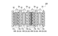
次に、図3および図4を参照しながら、本実施形態の単電池20の容器50内の構成について説明する。図3は拘束状態の単電池20の容器50内の状態ならびに単電池20の周辺構造を模式的に示す断面図である。
Next, the configuration within the
単電池20の容器50内には電極体80A〜80Dが収容されている。本実施形態の電極体80A〜80Dは上述したように扁平形状の捲回電極体80A〜80Dである。図3に示すように捲回電極体80A〜80Dの厚みは、捲回度合や状態(例えば電極体を構成する各材料(典型的には正極や負極、或いはセパレータ)の厚みのバラツキ、等)により不揃いになる場合がある。このことは、使用する捲回電極体80A〜80Dに応じて単電池20の容器50内の隙間(特に一対の側壁52、54と捲回電極体80との隙間)の寸法がまちまちとなることを意味する。
ここで、本実施形態においては、図4に示すような薄いシート状の絶縁性間隙充填部材10(以下「間隙充填シート」と略称する。)を用いることによって各単電池20の容器50内の隙間を塞ぐことができる。即ち、図3に示すように、容器50内の隙間(一対の側壁52、54と捲回電極体80との隙間)の大きさに合わせて適切な枚数(本実施形態では複数)の間隙充填シート10を当該隙間に挿入することによって、各単電池20の容器50内の隙間(一対の側壁52、54と捲回電極体80との隙間)を塞いでいる。
Here, in the present embodiment, by using a thin sheet-like insulating gap filling member 10 (hereinafter, abbreviated as “gap filling sheet”) as shown in FIG. The gap can be closed. That is, as shown in FIG. 3, a suitable number (a plurality in the present embodiment) of gap filling according to the size of the gap in the container 50 (the gap between the pair of
具体的には、ポリプロピレン等のポリオレフィン系樹脂から成る厚さ1mm以下(典型的には10〜1000μm、好ましくは100〜200μm)の間隙充填シート10を好適に使用することができる。或いは、アルミニウム製のシート表面に樹脂コーティングを施して絶縁処理したものを間隙充填シートとして使用してもよい。間隙充填シート10の材質及び厚さは、組電池100の構成条件(例えば各単電池20を拘束する際に加えられる荷重の大きさや容器内部の隙間の寸方など)にあわせて適宜変更することができる。
Specifically, a
本実施形態では、複数の間隙充填シート10のうちの少なくとも一つは流路側側壁52と捲回電極体80A〜80Dとの間に配置されており、且つ、残りの間隙充填シートは非流路側側壁54と捲回電極体80A〜80Dとの間に配置されている。図示した例では、流路側側壁52と捲回電極体80A〜80Dとの間に1枚の間隙充填シート10aが配置され、非流路側側壁54と捲回電極体80A〜80Dとの間に残り(本実施形態では2枚〜6枚)の間隙充填シート10bが配置されている。本実施形態では、図示されるように、流路側側壁52と電極体80A〜80Dとの間の距離が、非流路側側壁54と電極体80A〜80Dとの間の距離よりも短くなるように間隙充填シート10a,10bが配置されている。
In the present embodiment, at least one of the plurality of
このように容器50内に配置される間隙充填シートの分布を一方の側壁側(即ち非流路側側壁54の方)に偏らせつつ容器50内の隙間を塞ぐことにより、流路側側壁52と捲回電極体80A〜80Dとの間に配置された間隙充填シート10a全体(ここでは1枚)の厚みを、非流路側側壁54と捲回電極体80A〜80Dとの間に配置された間隙充填シート10b全体(ここでは2〜6枚)の厚みよりも薄くすることができる。
In this way, by closing the gap in the
上記構成の組電池100によれば、複数の単電池20のうちの幾つかに生じ得る容器50内の隙間、典型的には容器50内部に収容する電極体80A〜80Dの形状の不揃いに起因して生じる隙間を間隙充填部材10で塞ぐことができる。このことによって、拘束時に配列方向に加わる荷重によって幾つかの単電池20の外形が歪むことを防止して各単電池の形状(特に配列方向の厚み)を揃えることができる。
According to the assembled
加えて、流路側側壁52と電極体80A〜80Dとの間に配置された間隙充填部材10a全体の厚みが、非流路側側壁54と電極体80A〜80Dとの間に配置された間隙充填部材10b全体の厚みよりも薄くなるように、容器50内に配置される間隙充填部材の分布を偏らせつつ容器内の隙間を塞いでいるため、上記隙間の広い狭いに拘わらず、流路側側壁52と電極体80A〜80Dとの間の距離が非流路側側壁54と電極体80A〜80Dとの間の距離よりも短くなり、常に容器内の電極体80A〜80Dは流路側側壁52に近い位置に配置され得る。このため、容器50内で発生した熱(主として電極体80から発生した熱)を流路側側壁52方向(即ち流路46に向けて)速やかに放散することができる。
In addition, the thickness of the entire
従って、容器50に配置する間隙充填部材全体の厚みは同じであっても、流路側側壁52に近接する間隙充填部材10aと非流路側側壁54に近接する間隙充填部材10bとを同じ厚みに調整した場合と比較して、個々の単電池20の放熱性を高めることができ、組電池100の冷却効率を向上させることができる。その結果、例えば冷却ファンの小型化を実現することができ、組電池のコストを低減することが可能となる。また、冷却ファンの小型化は、組電池及びその周辺機器全体の体格(サイズ)そのものを低減することが可能となり、車両のように限られたスペースに収容(設置)する場合に好ましい。さらに冷却ファンの小型化は、ファン作動時の騒音低減にも寄与するため好ましい。
Therefore, even if the thickness of the entire gap filling member arranged in the
また、本実施形態では、各単電池20において流路46に近い側の間隙充填シート10aが同じ枚数(図3の例では1枚)となるように調整されているため、各単電池20における放熱性を均一化することができる。そのため、各単電池20の経年劣化の度合い等を同一にすることができる。
In the present embodiment, the
さらに、本実施形態では、図4に示すような一種類の同形状の間隙充填シート10a、10bを採用することによって、各単電池容器内の様々な大きさの隙間を効率よく充填する(塞ぐ)ことができる。
Further, in the present embodiment, by adopting one type of gap-filling
即ち、容器50内の隙間サイズに対応する枚数の間隙充填シート10を用意するとともに、流路側側壁52と電極体80との間に配置する間隙充填シート10aの枚数が非流路側側壁54と電極体80A〜80Dとの間に配置する間隙充填シート10bの枚数よりも少なくなるように、その使用枚数を調整することによって、数多くのサイズ・形状の間隙充填部材(例えば隙間を一度に充填し得るような厚みのあるブロック状充填部材)を取り揃えることなく、流路側側壁52と電極体80A〜80Dとの間に配置された間隙充填シート10a全体の厚みを非流路側側壁54と電極体80A〜80Dとの間に配置された間隙充填シート10b全体の厚みよりも薄くすることを容易に実現できる。
That is, the number of
なお、本実施形態で示すように、流路側側壁52と電極体80A〜80Dとの間に配置された間隙充填部材10全体の厚みは、組電池100を構成する各単電池20の容器50間で略同じ(図示した例では全て1枚)であることが好ましい。
As shown in the present embodiment, the thickness of the entire
かかる構成の組電池100によれば、単電池容器50内部からの放熱に最も寄与する流路側側壁52(即ち流路46に直に面する側壁52)と電極体80A〜80Dとの距離が各単電池20間で一定であり、従って放熱性を各単電池間で均一化することができる。そのため、各単電池20の経年劣化の度合い等を同一にすることができ、結果として組電池100の長寿命化を実現することができる。
According to the assembled
なお、本実施形態では、間隔保持板40を用いて冷却用媒体(典型的には空気)が通る流路46を形成したが、これに限らず、容器50の流路側側壁52に流路46を直接形成してもよい。例えば、容器50の流路側側壁52に凹部を設け、かかる凹部に冷却用媒体(典型的には空気)を導入するように構成することができる。
In the present embodiment, the
また、本実施形態では、容器50に挿入される間隙充填部材(シート)10a,10bの厚み調整は、当該間隙充填部材(シート)10a,10bの使用枚数(積層枚数)によって調整されているが、かかる形態に限られない。例えば、容器50内に相互に厚みが異なる少なくとも2種類の間隙充填部材(典型的にはシート)を挿入してもよい。例えば、図3に示す実施形態では、非流路側側壁54と捲回電極体80A〜80Dとの間に2枚〜6枚の間隙充填シート10bが容器内において積層するように挿入・配置されているが、その変更例として、かかる複数枚の間隙充填シート10bが一体になった場合と同等の厚みのある肉厚な間隙充填シート(典型的には1枚)を非流路側側壁54と捲回電極体80A〜80Dとの間に挿入・配置してもよい。このように、相対的に厚い間隙充填部材(例えば図3に符号10bで示す複数枚のシートが相互に接合されたような1枚の肉厚な間隙充填部材)を非流路側側壁54と電極体80A〜80Dとの間に配置し、他方、相対的に薄い間隙充填材(例えば図3に符号10aで示すシート1枚)を流路側側壁52と電極体80A〜80Dとの間に配置した場合も、図3に示す複数枚の間隙充填シート10bを用いた場合と同様の効果が得られ得る。
In the present embodiment, the thickness adjustment of the gap filling members (sheets) 10a and 10b inserted into the
或いはまた、間隙充填部材10を、流路側側壁52と電極体80A〜80Dとの間には配置せずに、非流路側側壁54と電極体80A〜80Dとの間にのみ配置してもよい。
Alternatively, the
即ち、図5に示すように、配列された各単電池20のうちの少なくとも一つの単電池容器50内(ここでは配列方向に並ぶ4個全ての単電池容器50内)に、一対の側壁52、54と電極体80A〜80Dとの隙間を塞ぐ間隙充填部材を一つ又は複数(ここでは複数の間隙充填シート10b)挿入し、かかる複数の間隙充填部材(複数の間隙充填シート10b)を、非流路側側壁54と電極体80A〜80Dとの間にのみ配置する(即ち流路側側壁52と電極体80A〜80Dとの間には配置しない)ことができる。
That is, as shown in FIG. 5, a pair of
かかる構成の組電池200によれば、単電池容器50内部からの放熱に最も寄与する流路側側壁52(即ち流路に直に面する側壁)と電極体80A〜80Dとが近接しており、結果、主として電極体80A〜80Dから発生した熱を、間隙充填部材10を介さずに電池容器50外(具体的には流路)へと速やかに放散させることができる。従って、個々の単電池20の放熱性をさらに高めることができ、延いては組電池200の冷却効率を一層向上させることができる。
According to the assembled
本願発明者は、本実施形態に係る組電池の効果を確認するために、単電池としてリチウムイオン二次電池(図示するような箱形(角型)の電池容器に収容された捲回型リチウムイオン電池)を所定方向に4個〜8個程度配列した組電池を用いて、充放電処理中の電池温度を測定する実験を行った。詳細には、各単電池を組電池に組み込む際に、各単電池容器の非流路側側壁(すなわち間隔保持板の流路に面していない側壁)にのみ間隙充填シートを挿入して厚み調整を行った組電池(例えば図5に示したような組電池)を用意した。そして、かかる組電池に対して30Aの充放電を30秒ずつ(充電30秒、放電30秒)20サイクル繰り返した。なお、この実験では冷却用媒体として空気(冷却風)を用い、充放電処理中の冷却風の風量は、35m3/hrとなるように設定した。 In order to confirm the effect of the assembled battery according to the present embodiment, the inventor of the present application uses a lithium-ion secondary battery (a wound lithium (contained in a box-shaped (square) battery container as shown)) as a single battery An experiment was conducted to measure the battery temperature during the charge / discharge treatment using an assembled battery in which about 4 to 8 ion batteries were arranged in a predetermined direction. Specifically, when each cell is incorporated into the assembled battery, the thickness is adjusted by inserting a gap filling sheet only into the non-flow channel side wall (that is, the side wall not facing the flow channel of the spacing plate) of each cell container. An assembled battery (for example, an assembled battery as shown in FIG. 5) was prepared. Then, charging / discharging 30 A was repeated for 30 seconds (charging for 30 seconds, discharging for 30 seconds) for 20 cycles with respect to the assembled battery. In this experiment, air (cooling air) was used as the cooling medium, and the air volume of the cooling air during the charge / discharge treatment was set to be 35 m 3 / hr.
このようにして得られた充放電処理中の電池温度を測定すると、最高43℃までの温度上昇に留めることができ、単電池容器内において流路側側壁と電極体との間に間隙充填シートを挿入しないことによって組電池の冷却効果が向上することを確認できた。 When the battery temperature during the charging / discharging treatment thus obtained is measured, the temperature rise can be kept up to 43 ° C., and a gap filling sheet is provided between the flow channel side wall and the electrode body in the unit cell container. It was confirmed that the cooling effect of the assembled battery was improved by not inserting it.
これに対し、容器内に配置する間隙充填シート全体の厚みを上記実験と同じ厚みとし、流路側側壁側の間隙充填シート全体と非流路側側壁側の間隙充填シート全体とを同じ厚みに調整した組電池を用いて、同じ条件下で実験を行ったところ、最高59℃まで電池の温度が上昇し、上述した実験と比べて組電池の冷却効果があまり得られないことが分かった。これにより、容器内に配置する間隙充填シート全体の厚みは同じであっても、その分布を偏らせつつ容器内の隙間を塞ぐことによる冷却効果向上のメリットが確認できた。 On the other hand, the thickness of the entire gap filling sheet disposed in the container was set to the same thickness as the above-described experiment, and the entire gap filling sheet on the channel side wall side and the entire gap filling sheet on the non-channel side wall side were adjusted to the same thickness. When an experiment was performed using the assembled battery under the same conditions, it was found that the temperature of the battery increased to a maximum of 59 ° C., and the cooling effect of the assembled battery could not be obtained much compared to the above-described experiment. Thereby, even if the thickness of the entire gap filling sheet arranged in the container is the same, the merit of improving the cooling effect by closing the gap in the container while biasing the distribution was confirmed.
本実施形態で使用され得る単電池20の構成及び単電池20を構成する各材料などについて詳述すると以下の通りである。
The configuration of the
本実施形態に係る捲回電極体80は、図6に示すように、通常のリチウムイオン電池の捲回電極体と同様、シート状正極82(以下「正極シート82」という。)とシート状負極84(以下「負極シート84」という。)を計2枚のシート状セパレータ86(以下「セパレータシート86」という。)と共に積層し、さらに当該正極シート82と負極シート84とをややずらしつつ捲回し、次いで得られた捲回体を側面方向から押しつぶして拉げさせることによって作製される扁平形状の捲回電極体80である。
As shown in FIG. 6, the
かかる捲回電極体80の捲回方向に対する横方向において、上記のとおりにややずらしつつ捲回された結果として、正極シート82および負極シート84の端の一部がそれぞれ捲回コア部分81(即ち正極シート82の正極活物質層形成部分と負極シート84の負極活物質層形成部分とセパレータシート86とが密に捲回された部分)から外方にはみ出ている。かかる正極側はみ出し部分(即ち正極活物質層の非形成部分)82Aおよび負極側はみ出し部分(即ち負極活物質層の非形成部分)84Aには、正極リード端子82Bおよび負極リード端子84Bがそれぞれ付設されており、それぞれ、上述の正極端子60および負極端子62と電気的に接続される。
As a result of the winding
なお、かかる捲回電極体80を構成する材料および部材自体は、従来のリチウムイオン電池の電極体と同様でよく、特に制限はない。例えば、正極シート82は長尺状の正極集電体の上にリチウムイオン電池用正極活物質層が付与されて形成され得る。正極集電体にはアルミニウム箔(本実施形態)その他の正極に適する金属箔が好適に使用される。正極活物質は従来からリチウムイオン電池に用いられる物質の一種または二種以上を特に限定することなく使用することができる。好適例として、LiMn2O4、LiCoO2、LiNiO2等が挙げられる。
In addition, the material and member itself which comprise this winding
一方、負極シート84は長尺状の負極集電体の上にリチウムイオン電池用負極活物質層が付与されて形成され得る。負極集電体には銅箔(本実施形態)その他の負極に適する金属箔が好適に使用される。負極活物質は従来からリチウムイオン電池に用いられる物質の一種または二種以上を特に限定することなく使用することができる。好適例として、グラファイトカーボン、アモルファスカーボン等の炭素系材料、リチウム含有遷移金属酸化物や遷移金属窒化物等が挙げられる。
On the other hand, the
また、正負極シート82,84間に使用される好適なセパレータシート86としては多孔質ポリオレフィン系樹脂で構成されたものが挙げられる。例えば、長さ2〜4m(例えば3.1m)、幅8〜12cm(例えば11cm)、厚さ5〜30μm(例えば25μm)程度の合成樹脂製(例えばポリエチレン等のポリオレフィン製)多孔質セパレータシートが好適に使用し得る。なお、電解質として固体電解質若しくはゲル状電解質を使用する場合には、セパレータが不要な場合(即ちこの場合には電解質自体がセパレータとして機能し得る。)があり得る。なお、単電池の容器内に収容する電極体は上記捲回タイプに限定されない。例えば正極シートと負極シートをセパレータ(或いはセパレータとしても機能し得る固体またはゲル状電解質)と共に交互に積層して成る積層タイプの電極体であってもよい。
Moreover, as a
続いて、容器50内に上記捲回電極体80と共に収容される電解質の構成について説明する。本実施形態の電解質は例えばLiPF6等のリチウム塩である。本実施形態では、適当量(例えば濃度1M)のLiPF6等のリチウム塩をジエチルカーボネートとエチレンカーボネートとの混合溶媒(例えば質量比1:1)のような非水電解液に溶解して電解液として使用している。捲回電極体80および間隙充填シート10を容器50に収容するとともに、上記電解液を注入して封止することによって本実施形態の単電池20は構築される。そして、単電池20を所定の方向に配列し、当該単電池20及び間隔保持板40をその配列方向に拘束することによって本実施形態の組電池100は構築される。
Then, the structure of the electrolyte accommodated in the
本実施形態に係る組電池100,200は、特に自動車等の車両に搭載されるモーター(電動機)用電源として好適に使用し得る。従って、本発明では、図7に模式的に示すように、かかる組電池100,200を電源として備える車両1(典型的には自動車、特にハイブリッド自動車、電気自動車、燃料電池自動車のような電動機を備える自動車)1を提供することができる。
The assembled
以上、本発明を好適な実施形態により説明してきたが、こうした記述は限定事項ではなく、勿論、種々の改変が可能である。 As mentioned above, although this invention was demonstrated by suitable embodiment, such description is not a limitation matter and of course various modifications are possible.
例えば、自動車等の車両に搭載する場合、より多くの単電池が直列に接続され得ると共に、組電池の主要部(単電池群、等)を保護するための外装カバー、車両の所定部位に当該組電池を固定するための部品、複数の組電池(電池モジュール)を相互に連結するための部品等が装備され得るが、このような装備の有無は本発明の技術的範囲を左右するものではない。 For example, when mounted on a vehicle such as an automobile, more unit cells can be connected in series, and an exterior cover for protecting the main part (unit cell group, etc.) of the assembled battery is applied to a predetermined part of the vehicle. A part for fixing the assembled battery, a part for interconnecting a plurality of assembled batteries (battery modules), and the like can be provided. However, the presence or absence of such equipment does not affect the technical scope of the present invention. Absent.
また、単電池の種類は上述したリチウムイオン電池に限られず、電極体構成材料や電解質が異なる種々の内容の電池、例えばリチウム金属やリチウム合金を負極とするリチウム二次電池、ニッケル水素電池、ニッケルカドミウム電池、或いは電気二重層キャパシタのようないわゆる物理電池であってもよい。 In addition, the type of unit cell is not limited to the above-described lithium ion battery, but batteries having various contents with different electrode body constituent materials and electrolytes, for example, lithium secondary batteries, nickel-metal hydride batteries, nickel batteries having lithium metal or a lithium alloy as a negative electrode A so-called physical battery such as a cadmium battery or an electric double layer capacitor may be used.
1 車両
10,10a,10b 間隙充填材(間隙充填シート)
20 単電池
40 間隔保持板
41 凹凸形状面
42 凸部
44 凹部
45 フラット面
46 空隙(流路)
50 容器
52 流路側側壁
54 非流路側側壁
60 正極端子
62 負極端子
64 接続具
72 ビーム材
76A,76B 拘束板
78 ビス
80,80A,80B,80C,80D 電極体
81 捲回コア部分
82 正極シート
82B 正極リード端子
84 負極シート
84B 負極リード端子
86 セパレータシート
100,200 組電池
1
20
50
Claims (9)
前記複数の単電池は各々、正極および負極を備える電極体と、該電極体を収容する容器とを備えており、
前記単電池容器の前記配列方向に並ぶ一対の側壁は、冷却用媒体が通る流路に直に面した流路側側壁と、該流路に直に面していない非流路側側壁とから成り、
前記配列された単電池のうちの少なくとも一つの単電池容器内には、前記一対の側壁と前記電極体との隙間を塞ぐ間隙充填部材が挿入されており、
ここで、前記流路側側壁と前記電極体との間の距離が、前記非流路側側壁と前記電極体との間の距離よりも短くなるように前記間隙充填部材が配置されていることを特徴とする、組電池。 An assembled battery in which a plurality of cells are arranged,
Each of the plurality of unit cells includes an electrode body including a positive electrode and a negative electrode, and a container for housing the electrode body,
The pair of side walls arranged in the arrangement direction of the unit cell containers are composed of a flow channel side wall directly facing a flow channel through which a cooling medium passes, and a non-flow channel side wall not directly facing the flow channel,
A gap filling member for closing a gap between the pair of side walls and the electrode body is inserted into at least one unit cell container of the arrayed unit cells,
Here, the gap filling member is arranged such that a distance between the flow channel side wall and the electrode body is shorter than a distance between the non-flow channel side wall and the electrode body. And an assembled battery.
前記複数の間隙充填部材のうちの少なくとも一つは前記流路側側壁と前記電極体との間に配置されており、且つ、残りの間隙充填部材は前記非流路側側壁と前記電極体との間に配置されており、
前記流路側側壁と前記電極体との間に配置された間隙充填部材全体の厚みが、前記非流路側側壁と前記電極体との間に配置された間隙充填部材全体の厚みよりも薄いことを特徴とする、請求項1に記載の組電池。 A plurality of gap filling members having the same thickness as the gap filling member are inserted into at least one unit cell container of the arranged unit cells,
At least one of the plurality of gap filling members is disposed between the flow channel side wall and the electrode body, and the remaining gap filling members are disposed between the non-flow channel side wall and the electrode body. Are located in
The thickness of the entire gap filling member disposed between the flow channel side wall and the electrode body is smaller than the thickness of the entire gap filling member disposed between the non-flow channel side wall and the electrode body. The assembled battery according to claim 1, wherein
前記間隙充填部材のうちの相対的に厚い間隙充填部材が前記非流路側側壁と前記電極体との間に配置されていることを特徴とする、請求項1〜3のいずれかに記載の組電池。 At least two types of gap filling members having different thicknesses as the gap filling member are inserted into at least one unit cell container among the arranged unit cells,
The group according to any one of claims 1 to 3, wherein a relatively thick gap filling member among the gap filling members is disposed between the non-flow channel side wall and the electrode body. battery.
前記間隔保持板の前記流路側側壁に対向する面には、前記冷却用媒体が通る流路を構成する凹部が形成されていることを特徴とする、請求項1〜5のいずれかに記載の組電池。 In the gap between the arranged single cells, an interval holding plate is arranged that is restrained in a state where a load is applied in the arrangement direction together with the single cells,
The recess facing the flow path through which the cooling medium passes is formed on the surface of the spacing plate facing the flow path side wall, according to any one of claims 1 to 5. Assembled battery.
該シート状間隙充填部材が前記側壁と前記電極体との間に1枚若しくは複数枚挿入されていることを特徴とする、請求項1〜6のいずれかに記載の組電池。 The gap filling member is formed in a sheet shape having a predetermined thickness,
The assembled battery according to claim 1, wherein one or a plurality of the sheet-like gap filling members are inserted between the side wall and the electrode body.
前記複数の単電池は、前記捲回電極体の扁平面が対向するように配列され且つ該配列方向に荷重が加えられた状態で拘束されており、
前記複数の単電池の少なくとも一つについて前記側壁と前記捲回電極体の扁平面との間に前記間隙充填部材が挿入されている、請求項1〜7のいずれかに記載の組電池。 Each of the plurality of single cells is provided with a flat wound electrode body formed by winding a sheet-like positive electrode and a sheet-like negative electrode,
The plurality of single cells are arranged so that the flat surfaces of the wound electrode bodies are opposed to each other and are restrained in a state where a load is applied in the arrangement direction,
The assembled battery according to claim 1, wherein the gap filling member is inserted between the side wall and the flat surface of the wound electrode body for at least one of the plurality of unit cells.
Priority Applications (6)
| Application Number | Priority Date | Filing Date | Title |
|---|---|---|---|
| JP2008056699A JP4587055B2 (en) | 2008-03-06 | 2008-03-06 | Assembled battery |
| US12/918,559 US8551631B2 (en) | 2008-03-06 | 2009-03-03 | Assembled battery, and vehicle equipped with the assembled battery |
| PCT/IB2009/000403 WO2009109834A1 (en) | 2008-03-06 | 2009-03-03 | Assembled battery, and vehicle equipped with the assembled battery |
| EP09716909A EP2248207B1 (en) | 2008-03-06 | 2009-03-03 | Assembled battery, and vehicle equipped with the assembled battery |
| CN2009801078068A CN101960643B (en) | 2008-03-06 | 2009-03-03 | Assembled battery, and vehicle equipped with assembled battery |
| KR1020107019637A KR101238060B1 (en) | 2008-03-06 | 2009-03-03 | Assembled battery, and vehicle equipped with the assembled battery |
Applications Claiming Priority (1)
| Application Number | Priority Date | Filing Date | Title |
|---|---|---|---|
| JP2008056699A JP4587055B2 (en) | 2008-03-06 | 2008-03-06 | Assembled battery |
Publications (2)
| Publication Number | Publication Date |
|---|---|
| JP2009212055A JP2009212055A (en) | 2009-09-17 |
| JP4587055B2 true JP4587055B2 (en) | 2010-11-24 |
Family
ID=40627628
Family Applications (1)
| Application Number | Title | Priority Date | Filing Date |
|---|---|---|---|
| JP2008056699A Active JP4587055B2 (en) | 2008-03-06 | 2008-03-06 | Assembled battery |
Country Status (6)
| Country | Link |
|---|---|
| US (1) | US8551631B2 (en) |
| EP (1) | EP2248207B1 (en) |
| JP (1) | JP4587055B2 (en) |
| KR (1) | KR101238060B1 (en) |
| CN (1) | CN101960643B (en) |
| WO (1) | WO2009109834A1 (en) |
Families Citing this family (27)
| Publication number | Priority date | Publication date | Assignee | Title |
|---|---|---|---|---|
| DE102010043628A1 (en) * | 2010-03-05 | 2011-09-08 | Mahle International Gmbh | Cooling element and energy storage |
| US8980807B2 (en) | 2010-05-21 | 2015-03-17 | Cargill, Incorporated | Blown and stripped blend of soybean oil and corn stillage oil |
| JP5315311B2 (en) * | 2010-08-31 | 2013-10-16 | トヨタ自動車株式会社 | Power storage device |
| JP5804323B2 (en) | 2011-01-07 | 2015-11-04 | 株式会社Gsユアサ | Power storage element and power storage device |
| JP6020942B2 (en) * | 2011-01-07 | 2016-11-02 | 株式会社Gsユアサ | Power storage device |
| CA2837073C (en) | 2011-05-27 | 2020-04-07 | Cargill, Incorporated | Bio-based binder systems |
| JP5692045B2 (en) * | 2011-12-21 | 2015-04-01 | 株式会社豊田自動織機 | Module and vehicle |
| JP6083211B2 (en) * | 2011-12-28 | 2017-02-22 | 株式会社Gsユアサ | Power supply |
| KR20130118716A (en) | 2012-04-20 | 2013-10-30 | 주식회사 엘지화학 | Electrode assembly, battery cell and device comprising the same |
| EP2885830B1 (en) | 2012-08-16 | 2017-10-11 | Enovix Corporation | Electrode structures for three-dimensional batteries |
| KR101387424B1 (en) | 2012-11-22 | 2014-04-25 | 주식회사 엘지화학 | Electrode assembly composed of electrode units with equal widths and different lengths, battery cell and device including the same |
| US9991490B2 (en) | 2013-03-15 | 2018-06-05 | Enovix Corporation | Separators for three-dimensional batteries |
| JP2015018790A (en) | 2013-06-14 | 2015-01-29 | 株式会社Gsユアサ | Power storage module |
| JP6665876B2 (en) * | 2013-06-14 | 2020-03-13 | 株式会社Gsユアサ | Power storage module |
| JP6060840B2 (en) * | 2013-07-17 | 2017-01-18 | 株式会社豊田自動織機 | Power storage module |
| JP6103506B2 (en) * | 2014-07-22 | 2017-03-29 | 旭ファイバーグラス株式会社 | Inorganic fiber insulation |
| JP6135660B2 (en) | 2014-12-25 | 2017-05-31 | トヨタ自動車株式会社 | Assembled battery |
| EP4113682A1 (en) | 2015-05-14 | 2023-01-04 | Enovix Corporation | Longitudinal constraints for energy storage devices |
| JP6217987B2 (en) * | 2015-06-15 | 2017-10-25 | トヨタ自動車株式会社 | Assembled battery |
| KR102391925B1 (en) | 2016-05-13 | 2022-04-28 | 에노빅스 코오퍼레이션 | Dimensional Constraints for 3D Batteries |
| US11063299B2 (en) | 2016-11-16 | 2021-07-13 | Enovix Corporation | Three-dimensional batteries with compressible cathodes |
| US10256507B1 (en) | 2017-11-15 | 2019-04-09 | Enovix Corporation | Constrained electrode assembly |
| JP2021503165A (en) | 2017-11-15 | 2021-02-04 | エノビクス・コーポレイションEnovix Corporation | Electrode assembly and rechargeable battery |
| US11211639B2 (en) | 2018-08-06 | 2021-12-28 | Enovix Corporation | Electrode assembly manufacture and device |
| CN109802064B (en) * | 2018-12-20 | 2023-12-05 | 河南新太行电源股份有限公司 | Battery mould structure of adjustable extension |
| EP4200921A1 (en) | 2020-09-18 | 2023-06-28 | Enovix Corporation | Processes for delineating a population of electrode structures in a web using a laser beam |
| CN116783744A (en) | 2020-12-09 | 2023-09-19 | 艾诺维克斯公司 | Method and apparatus for manufacturing electrode assembly of secondary battery |
Citations (2)
| Publication number | Priority date | Publication date | Assignee | Title |
|---|---|---|---|---|
| JP2008108457A (en) * | 2006-10-23 | 2008-05-08 | Toyota Motor Corp | Battery pack, and its manufacturing method |
| JP2008108651A (en) * | 2006-10-27 | 2008-05-08 | Toyota Motor Corp | Battery pack, and its manufacturing method |
Family Cites Families (11)
| Publication number | Priority date | Publication date | Assignee | Title |
|---|---|---|---|---|
| JP3530556B2 (en) * | 1993-10-21 | 2004-05-24 | キヤノン株式会社 | Image forming apparatus and image forming method |
| JPH09186803A (en) * | 1996-01-06 | 1997-07-15 | Minolta Co Ltd | Image processor |
| JP3555124B2 (en) | 1996-01-19 | 2004-08-18 | 日本電池株式会社 | Lithium ion battery |
| EP0814530A1 (en) * | 1996-06-18 | 1997-12-29 | Alcatel | Electrochemical generator |
| DE29612571U1 (en) * | 1996-07-19 | 1996-09-12 | Varta Batterie | Multi-cell accumulator battery with cooling |
| JP4220649B2 (en) | 1999-06-10 | 2009-02-04 | パナソニック株式会社 | Assembled battery |
| JP4921629B2 (en) * | 2000-03-31 | 2012-04-25 | パナソニック株式会社 | Fluid-cooled battery pack system |
| JP2001306655A (en) * | 2000-04-26 | 2001-11-02 | Ricoh Co Ltd | System and method for printing, and computer-readable recording medium with recorded program making computer implement the same method |
| JP3972885B2 (en) | 2003-10-10 | 2007-09-05 | 日産自動車株式会社 | Assembled battery |
| JP4756821B2 (en) * | 2003-11-19 | 2011-08-24 | キヤノン株式会社 | Document management apparatus, control method therefor, and program |
| JP4457931B2 (en) | 2005-03-17 | 2010-04-28 | トヨタ自動車株式会社 | Battery module |
-
2008
- 2008-03-06 JP JP2008056699A patent/JP4587055B2/en active Active
-
2009
- 2009-03-03 WO PCT/IB2009/000403 patent/WO2009109834A1/en active Application Filing
- 2009-03-03 US US12/918,559 patent/US8551631B2/en active Active
- 2009-03-03 KR KR1020107019637A patent/KR101238060B1/en active IP Right Grant
- 2009-03-03 EP EP09716909A patent/EP2248207B1/en active Active
- 2009-03-03 CN CN2009801078068A patent/CN101960643B/en active Active
Patent Citations (2)
| Publication number | Priority date | Publication date | Assignee | Title |
|---|---|---|---|---|
| JP2008108457A (en) * | 2006-10-23 | 2008-05-08 | Toyota Motor Corp | Battery pack, and its manufacturing method |
| JP2008108651A (en) * | 2006-10-27 | 2008-05-08 | Toyota Motor Corp | Battery pack, and its manufacturing method |
Also Published As
| Publication number | Publication date |
|---|---|
| EP2248207B1 (en) | 2012-06-20 |
| EP2248207A1 (en) | 2010-11-10 |
| CN101960643A (en) | 2011-01-26 |
| WO2009109834A1 (en) | 2009-09-11 |
| JP2009212055A (en) | 2009-09-17 |
| KR101238060B1 (en) | 2013-02-27 |
| US20110008656A1 (en) | 2011-01-13 |
| CN101960643B (en) | 2013-06-19 |
| KR20100110386A (en) | 2010-10-12 |
| US8551631B2 (en) | 2013-10-08 |
Similar Documents
| Publication | Publication Date | Title |
|---|---|---|
| JP4587055B2 (en) | Assembled battery | |
| JP4501080B2 (en) | Battery pack and manufacturing method thereof | |
| JP4630855B2 (en) | Battery pack and manufacturing method thereof | |
| JP2008108651A (en) | Battery pack, and its manufacturing method | |
| JP4204237B2 (en) | Lithium secondary cell and connection structure of lithium secondary cell | |
| US10263276B2 (en) | Producing method of assembled battery | |
| WO2009061088A1 (en) | Battery cell having improved thermal stability and middle or large-sized battery module employed with the same | |
| KR102170472B1 (en) | Multi cavity battery module | |
| US11177499B2 (en) | Assembled battery | |
| JP2009048965A (en) | Battery pack, and manufacturing method thereof | |
| JP2008282648A (en) | Battery pack | |
| JP2010113861A (en) | Battery pack | |
| JP5344237B2 (en) | Assembled battery | |
| US8124265B2 (en) | Power storage device | |
| JP2008287916A (en) | Battery pack | |
| JP3804701B2 (en) | Lithium battery for assembled battery and assembled battery | |
| JP2020061383A (en) | Battery pack | |
| JP6660569B2 (en) | Manufacturing method of assembled battery | |
| JP7174326B2 (en) | assembled battery |
Legal Events
| Date | Code | Title | Description |
|---|---|---|---|
| A977 | Report on retrieval |
Free format text: JAPANESE INTERMEDIATE CODE: A971007 Effective date: 20100625 |
|
| TRDD | Decision of grant or rejection written | ||
| A01 | Written decision to grant a patent or to grant a registration (utility model) |
Free format text: JAPANESE INTERMEDIATE CODE: A01 Effective date: 20100812 |
|
| A01 | Written decision to grant a patent or to grant a registration (utility model) |
Free format text: JAPANESE INTERMEDIATE CODE: A01 |
|
| A61 | First payment of annual fees (during grant procedure) |
Free format text: JAPANESE INTERMEDIATE CODE: A61 Effective date: 20100825 |
|
| R151 | Written notification of patent or utility model registration |
Ref document number: 4587055 Country of ref document: JP Free format text: JAPANESE INTERMEDIATE CODE: R151 |
|
| FPAY | Renewal fee payment (event date is renewal date of database) |
Free format text: PAYMENT UNTIL: 20130917 Year of fee payment: 3 |