JP6033552B2 - Wireless power apparatus and method - Google Patents
Wireless power apparatus and method Download PDFInfo
- Publication number
- JP6033552B2 JP6033552B2 JP2012020946A JP2012020946A JP6033552B2 JP 6033552 B2 JP6033552 B2 JP 6033552B2 JP 2012020946 A JP2012020946 A JP 2012020946A JP 2012020946 A JP2012020946 A JP 2012020946A JP 6033552 B2 JP6033552 B2 JP 6033552B2
- Authority
- JP
- Japan
- Prior art keywords
- antenna
- power
- antenna circuit
- loop
- transmitter
- Prior art date
- Legal status (The legal status is an assumption and is not a legal conclusion. Google has not performed a legal analysis and makes no representation as to the accuracy of the status listed.)
- Expired - Fee Related
Links
Images


Classifications
-
- H—ELECTRICITY
- H01—ELECTRIC ELEMENTS
- H01Q—ANTENNAS, i.e. RADIO AERIALS
- H01Q7/00—Loop antennas with a substantially uniform current distribution around the loop and having a directional radiation pattern in a plane perpendicular to the plane of the loop
- H01Q7/005—Loop antennas with a substantially uniform current distribution around the loop and having a directional radiation pattern in a plane perpendicular to the plane of the loop with variable reactance for tuning the antenna
-
- H—ELECTRICITY
- H02—GENERATION; CONVERSION OR DISTRIBUTION OF ELECTRIC POWER
- H02J—ELECTRIC POWER NETWORKS; CIRCUIT ARRANGEMENTS OR SYSTEMS FOR SUPPLYING OR DISTRIBUTING ELECTRIC POWER; SYSTEMS FOR STORING ELECTRIC ENERGY
- H02J50/00—Circuit arrangements or systems for wireless supply or distribution of electric power
- H02J50/10—Circuit arrangements or systems for wireless supply or distribution of electric power using inductive coupling
- H02J50/12—Circuit arrangements or systems for wireless supply or distribution of electric power using inductive coupling of the resonant type
-
- H—ELECTRICITY
- H02—GENERATION; CONVERSION OR DISTRIBUTION OF ELECTRIC POWER
- H02J—ELECTRIC POWER NETWORKS; CIRCUIT ARRANGEMENTS OR SYSTEMS FOR SUPPLYING OR DISTRIBUTING ELECTRIC POWER; SYSTEMS FOR STORING ELECTRIC ENERGY
- H02J50/00—Circuit arrangements or systems for wireless supply or distribution of electric power
- H02J50/20—Circuit arrangements or systems for wireless supply or distribution of electric power using microwaves or radio frequency waves
- H02J50/23—Circuit arrangements or systems for wireless supply or distribution of electric power using microwaves or radio frequency waves characterised by the type of transmitting antennas, e.g. directional array antennas or Yagi antennas
-
- H—ELECTRICITY
- H02—GENERATION; CONVERSION OR DISTRIBUTION OF ELECTRIC POWER
- H02J—ELECTRIC POWER NETWORKS; CIRCUIT ARRANGEMENTS OR SYSTEMS FOR SUPPLYING OR DISTRIBUTING ELECTRIC POWER; SYSTEMS FOR STORING ELECTRIC ENERGY
- H02J50/00—Circuit arrangements or systems for wireless supply or distribution of electric power
- H02J50/20—Circuit arrangements or systems for wireless supply or distribution of electric power using microwaves or radio frequency waves
- H02J50/27—Circuit arrangements or systems for wireless supply or distribution of electric power using microwaves or radio frequency waves characterised by the type of receiving antennas, e.g. rectennas
-
- H—ELECTRICITY
- H02—GENERATION; CONVERSION OR DISTRIBUTION OF ELECTRIC POWER
- H02J—ELECTRIC POWER NETWORKS; CIRCUIT ARRANGEMENTS OR SYSTEMS FOR SUPPLYING OR DISTRIBUTING ELECTRIC POWER; SYSTEMS FOR STORING ELECTRIC ENERGY
- H02J50/00—Circuit arrangements or systems for wireless supply or distribution of electric power
- H02J50/50—Circuit arrangements or systems for wireless supply or distribution of electric power using additional energy repeaters between transmitting devices and receiving devices
-
- H—ELECTRICITY
- H02—GENERATION; CONVERSION OR DISTRIBUTION OF ELECTRIC POWER
- H02J—ELECTRIC POWER NETWORKS; CIRCUIT ARRANGEMENTS OR SYSTEMS FOR SUPPLYING OR DISTRIBUTING ELECTRIC POWER; SYSTEMS FOR STORING ELECTRIC ENERGY
- H02J50/00—Circuit arrangements or systems for wireless supply or distribution of electric power
- H02J50/90—Circuit arrangements or systems for wireless supply or distribution of electric power involving detection or optimisation of position, e.g. alignment
-
- H—ELECTRICITY
- H02—GENERATION; CONVERSION OR DISTRIBUTION OF ELECTRIC POWER
- H02J—ELECTRIC POWER NETWORKS; CIRCUIT ARRANGEMENTS OR SYSTEMS FOR SUPPLYING OR DISTRIBUTING ELECTRIC POWER; SYSTEMS FOR STORING ELECTRIC ENERGY
- H02J50/00—Circuit arrangements or systems for wireless supply or distribution of electric power
- H02J50/70—Circuit arrangements or systems for wireless supply or distribution of electric power involving the reduction of electric, magnetic or electromagnetic leakage fields
-
- H—ELECTRICITY
- H02—GENERATION; CONVERSION OR DISTRIBUTION OF ELECTRIC POWER
- H02J—ELECTRIC POWER NETWORKS; CIRCUIT ARRANGEMENTS OR SYSTEMS FOR SUPPLYING OR DISTRIBUTING ELECTRIC POWER; SYSTEMS FOR STORING ELECTRIC ENERGY
- H02J50/00—Circuit arrangements or systems for wireless supply or distribution of electric power
- H02J50/80—Circuit arrangements or systems for wireless supply or distribution of electric power involving the exchange of data, concerning supply or distribution of electric power, between transmitting devices and receiving devices
Landscapes
- Engineering & Computer Science (AREA)
- Computer Networks & Wireless Communication (AREA)
- Power Engineering (AREA)
- Physics & Mathematics (AREA)
- Electromagnetism (AREA)
- Near-Field Transmission Systems (AREA)
- Details Of Aerials (AREA)
- Charge And Discharge Circuits For Batteries Or The Like (AREA)
- Magnetic Resonance Imaging Apparatus (AREA)
- Aerials With Secondary Devices (AREA)
Description
[関連出願]
本出願は2006年4月21日出願され、「無線回線を介して電子デバイスに電力供給するための方法及びシステム(Method and System for Powering an Electronic Device Via a Wireless Link)」と題する共有及び同時係属の米国特許出願第11/408,793号、及び2007年1月17日出願され、「無線回線を介して電子デバイスにエネルギーを供給するための方法及び装置(Method and Apparatus for Delivering Energy to an Electrical or Electronic Device Via a Wireless Link)」と題する米国特許出願第111654,883号に関係し、前述の各々は参照によってその全体がここに組込まれている。
[Related applications]
This application was filed on April 21, 2006 and is shared and co-pending entitled “Method and System for Powering an Electronic Device Via a Wireless Link”. No. 11 / 408,793, filed on Jan. 17, 2007, and “Method and Apparatus for Delivering Energy to an Electrical”. or Electronic Device Via a Wireless Link), which is incorporated herein by reference in its entirety.
本出願は2007年3月2日に出願された仮出願番号第60/904,628号からの優先権を要求する、その引例によってこれと共にここに組込まれている。 This application is hereby incorporated herein by reference, which requests priority from provisional application No. 60 / 904,628, filed Mar. 2, 2007.
[著作権]
この特許文書の開示の一部は著作権保護に制約される材料を含む。それは特許・商標局の特許ファイルまたは記録に載っているので、著作権所有者はあらゆる特許文書または特許開示によるファクシミリ再生に対して反対をしないが、他の場合は全ての著作権権利を留保する。
[Copyright]
Part of the disclosure of this patent document contains material that is subject to copyright protection. The copyright owner does not object to facsimile reproduction by any patent document or patent disclosure, but it reserves all copyright rights otherwise, as it appears in the Patent and Trademark Office patent file or record .
全ての図、表、及び添付書類(Exhibits)は著作権(c)2006、2007第三オプション、LLCであり、全ての権利が留保される。 All figures, tables, and Exhibits are Copyright (c) 2006, 2007 Third Option, LLC and all rights are reserved.
ポータブル・デバイスへの電力の供給は電力供給を実行するのに様々な形式の電線(wires)を大抵は使用する。携帯電話、ポータブル・コンピューター、または電池のような蓄積電力により動作する任意の他のデバイスといったデバイスは全てデバイスを動作させ、且つ/または電池を充電するためにそのような動力源を必要とし、且つ使用する。 Supplying power to portable devices often uses various types of wires to perform the power supply. Devices such as cell phones, portable computers, or any other device that operates with stored power, such as a battery, all require such a power source to operate the device and / or charge the battery, and use.
無線電力転送の技術がここに開示される。 Techniques for wireless power transfer are disclosed herein.
実施例は受信源への無線電力転送の使用を説明する。 The example illustrates the use of wireless power transfer to the receiving source.
ここに使用される、用語「無線電力(wireless power)」及び「無線エネルギー(wireless energy)」は有線接続を使用することなく一つの点、領域、場所またはデバイスと他の間で伝送され、電場、磁場、電磁エネルギー、またはそうでないものと関連するものを含めて、制限なく任意の形の動力またはエネルギーを含む。 As used herein, the terms “wireless power” and “wireless energy” are transmitted between one point, region, place or device and the other without using a wired connection, Including any form of power or energy without limitation, including those associated with magnetic fields, electromagnetic energy, or otherwise.
実施例は無線電力供給及び充電システムを開示する。実施例はそれが別の品目、例えば、机または棚に埋込まれ、または壁に埋込まれ、または壁、床、扉などの別の構造物または表面に埋込まれることが可能なサイズの送信器を使用することを述べる。受信器はユーザーによって運ばれ、またはポータブル・デバイス、乗物に、またはランプ、トースター、壁掛けフラット・スクリーン・テレビ、コンピューター或いはコンピューター化デバイス、PDA、個人メディア・デバイス等といった静止デバイスと共に搭載された、小さな移動ユニットまたはクライアント・デバイスと関連する。受信器が送信器の範囲内にあるとき、電力は移動ユニットに転送される。 Embodiments disclose a wireless power supply and charging system. Examples are of a size that allows it to be embedded in another item, such as a desk or shelf, or embedded in a wall, or embedded in another structure or surface such as a wall, floor, door, etc. Describe the use of a transmitter. The receiver can be carried by the user or mounted on a portable device, vehicle or with a stationary device such as a lamp, toaster, wall-mounted flat screen TV, computer or computerized device, PDA, personal media device, etc. Associated with a mobile unit or client device. When the receiver is within range of the transmitter, power is transferred to the mobile unit.
一つの実施例では、無線電力供給−充電システムは実質的には非変調信号またはビーコン(例えば、キャリアのみ)を送る送信器に基づいて開示される。受信器は送信器の放射場からエネルギーを取出すように同調される。その受信器は電子デバイスに電力を供給し、或いは電池を充電する。 In one embodiment, a wireless power supply-charging system is disclosed based on a transmitter that sends a substantially unmodulated signal or beacon (eg, carrier only). The receiver is tuned to extract energy from the transmitter radiation field. The receiver supplies power to the electronic device or charges the battery.
他の実施例は僅かに変調されるビーコンを使用する。 Other embodiments use a slightly modulated beacon.
多数の受信器が使用される。多数の送信器は一つまたは多数の受信器に伝送するために使用される。 A number of receivers are used. Multiple transmitters are used to transmit to one or multiple receivers.
このシステムによって使用されるアンテナはエネルギー伝送及び受取の効率的な手段を割当てる。アンテナはアンテナに利用可能な空間が制限される移動、携帯用デバイスに適合できるように小型であることが望ましい。実施例は、伝送され、且つ受取られる電力に関する特定の特性及び環境に高効率なアンテナを述べる。 The antenna used by this system assigns an efficient means of energy transmission and reception. The antenna is preferably small so that it can be adapted to mobile and portable devices where the space available for the antenna is limited. The embodiments describe antennas that are highly efficient for specific characteristics and environments regarding the power transmitted and received.
非常に効率的であるが小さなアンテナは一般的にそれが効率的である狭い周波数帯を持つことをアンテナ理論は示唆する。従って、当業者はより柔軟な伝送及び/または受信特性を可能にするためにこれらのアンテナの使用を回避した。実施例では、適応同調回路が効率的で、なお狭帯域のアンテナの同調を可能にするためにある形状で使用される。 Antenna theory suggests that a very efficient but small antenna generally has a narrow frequency band in which it is efficient. Thus, those skilled in the art have avoided the use of these antennas to allow for more flexible transmission and / or reception characteristics. In an embodiment, an adaptive tuning circuit is used in some form to be efficient and still allow tuning of a narrowband antenna.
一つの実施例は進行電磁波の形でエネルギーを自由空間に送るのではなく、送信アンテナの近接場にエネルギーを蓄えることによる二つのアンテナの間の効率的な電力転送を述べる。この実施例はアンテナの品質因子(Q)を増加させる。これは放射抵抗(Rr)及び損失抵抗(Rl)を減少させることができる。 One embodiment describes efficient power transfer between two antennas by storing energy in the near field of the transmitting antenna, rather than sending energy in the form of traveling electromagnetic waves to free space. This embodiment increases the quality factor (Q) of the antenna. This can reduce radiation resistance (R r ) and loss resistance (R l ).
一つの実施例では、二つの高Qアンテナは電力を他方に誘導する一つのアンテナと緩く結合された変圧器に同様に反応するように置かれる。それらのアンテナは1000より大きなQを持つ。 In one embodiment, the two high Q antennas are placed to react similarly to a transformer that is loosely coupled to one antenna that directs power to the other. Those antennas have a Q greater than 1000.
別の実施例は最大許容照射(Maximum Permissible Exposure:MPE)を述べる(ここでは(他と同様に)最大照射限界はヨーロッパ及び米国の規格によって定義される)。それらは電力密度限界(W/m2)、磁場限界(A/m)及び電場限界(V/m)に関して定義される。その限界は自由空間のインピーダンス、377Wを通して関係する。 Another example describes Maximum Permissible Exposure (MPE) (here (as with others) the maximum exposure limit is defined by European and US standards). They are defined in terms of power density limit (W / m 2 ), magnetic field limit (A / m) and electric field limit (V / m). The limit is related through free space impedance, 377W.
米国では、適用可能な規格はFCC CFR表題47:§2.1091無線周波数放射線照射評価:移動デバイスである。移動デバイスは少なくとも20cmの離間距離が送信器の放射構造体とユーザーまたは近くの人の身体の間で保たれて使用されるように設計された送信デバイスである。評価のために使用される限界は表題47−§1.1310無線周波数放射線照射限界の§1.310に指定される(表1を見よ)。 In the United States, the applicable standard is FCC CFR Title 47: § 2.091 Radio Frequency Radiation Assessment: Mobile Device. A mobile device is a transmitting device designed to be used with a separation distance of at least 20 cm maintained between the transmitter radiating structure and the body of a user or a nearby person. The limits used for the evaluation are specified in §1.310 of the title 47-§1.1310 radio frequency radiation limits (see Table 1).
表1:放射線照射のFCC限界は最大許容照射(MAXIMUM PERMISSIBLE EXPOSURE:MPE)を制限する。

ヨーロッパでは、適用可能な規格はEN60215である。これはICNIRP(非イオン化放射線保護に関する国際委員会)指針[ICN]から導かれてきた。その限界は表2に与えられる。
電力密度限界及び磁場限界は一つの実施例において特別な関心がある。表1及び表2からのデータを使用して、限界曲線が決定できる。図1はFCC限界曲線100及びEN曲線102による電力密度のプロットを示す。図2はFCC曲線200、及びEN曲線202による最大磁場(H)のプロットを示す。
The power density limit and the magnetic field limit are of particular interest in one embodiment. Using the data from Table 1 and Table 2, a limit curve can be determined. FIG. 1 shows a plot of power density according to FCC
図1及び2はいかに米国の限界が30MHz以下の周波数でよりおおらかであり、そして低周波でアンテナ効率低減の影響を相殺するかを例示している。この研究はどの周波数が最も無線電力転送に最良であるかを知るために周波数の範囲を試験する。 FIGS. 1 and 2 illustrate how the US limits are more loose at frequencies below 30 MHz and offset the effects of antenna efficiency reduction at low frequencies. This study tests a range of frequencies to find out which frequency is best for wireless power transfer.
本出願はまた無線エネルギー及び電力転送の様々な形態の典型的な理論解析を提供する。 The application also provides typical theoretical analysis of various forms of wireless energy and power transfer.
ここに開示された実施例はアンテナ型式を述べる。 The embodiments disclosed herein describe antenna types.
ループ・アンテナは「磁気的(magnetic)」アンテナであり、そして双極子(それは「電気的(electric)」アンテナである)よりその環境の変化に対して感度が低い。そのデバイスが浮遊キャパシタンス、または他の影響によるその環境の変化にさらされるとき、例えば、テーブル上に置かれ、手に保持され、またはポケットに入れられるとき、ループ・アンテナにはある利点がある。実施例では、エア・ループ・アンテナが使用される。別の実施例はフェライト・コアを持つループ・アンテナを使用し、または他のものが使用される。 A loop antenna is a “magnetic” antenna and is less sensitive to changes in its environment than a dipole (which is an “electric” antenna). Loop antennas have certain advantages when the device is exposed to changes in its environment due to stray capacitance, or other effects, for example when placed on a table, held in a hand, or pocketed. In the embodiment, an air loop antenna is used. Alternative embodiments use a loop antenna with a ferrite core, or others are used.
一つの実施例では、エア・ループ・アンテナがフェライト・コアを持つループ・アンテナより好まれる。エア・ループ・アンテナは永久磁石またはその周辺における他の磁気的影響による脱調に対して強い。フェライト・コアは損失を引起こすので、一般に、エア・ループ・アンテナはフェライト・ループ・アンテナより効率的であろう。フェライト・アンテナは大抵重く、そして一般的にその内部に要素部品(components)を置くことができない。一方、他の要素部品はエア・ループ・アンテナのループの中に置くことができる。ループの形状要素は充電されるあるポータブル・デバイスの形状要素の中に適合するように修正され、或いは他の場合には適応される。 In one embodiment, an air loop antenna is preferred over a loop antenna with a ferrite core. Air loop antennas are resistant to step-out due to permanent magnets or other magnetic influences around them. In general, an air loop antenna will be more efficient than a ferrite loop antenna because the ferrite core causes losses. Ferrite antennas are often heavy and generally cannot have components inside them. On the other hand, other component parts can be placed in the loop of the air loop antenna. The loop shape element is modified to fit within the shape element of one portable device being charged, or otherwise adapted.
同一型式のアンテナが送信器と受信器の両方に使用される。送信及び受信アンテナは同じか、異なるサイズであってもよい。 The same type of antenna is used for both transmitter and receiver. The transmit and receive antennas may be the same or different sizes.
実施例はアンテナ回路の一部になる同調回路を述べる。典型的なループ・アンテナは本来誘導的である。容量性要素(capacitive element)はアンテナにおいて共振を誘起する同調回路に使用される。ループ・アンテナが双極子アンテナよりその環境の変化に対して感度が低いとしても、それはその環境の変化によっていくらかの程度まだ脱調されるであろう。従って、その間の回線の品質を維持するために、送信器アンテナか受信器アンテナのいずれかまたは両方を適応的に同調させることはある実施例において望ましい。 The example describes a tuning circuit that becomes part of the antenna circuit. A typical loop antenna is inductive in nature. Capacitive elements are used in tuning circuits that induce resonance in the antenna. Even if a loop antenna is less sensitive to changes in its environment than a dipole antenna, it will still be stepped out to some extent by changes in its environment. Accordingly, it may be desirable in certain embodiments to adaptively tune either or both the transmitter antenna and the receiver antenna in order to maintain the quality of the line in between.
適応同調は一つの実施例では回路の共振周波数を調整するためにループ・アンテナと直列に使用される容量性要素の値を変えることによって達成される。送信器及び/または受信器における適応同調回路。目標は全体の受信器回路のQができる限り劣化されないことを保証するために高い品質要素(Q)を持つ同調部品を選ぶことである。実施例では、高Qは狭い帯域幅を犠牲にしてでも効率を最大限にするために使用される。 Adaptive tuning is achieved in one embodiment by changing the value of the capacitive element used in series with the loop antenna to adjust the resonant frequency of the circuit. Adaptive tuning circuit in the transmitter and / or receiver. The goal is to select a tuning component with a high quality factor (Q) to ensure that the overall receiver circuit Q is not degraded as much as possible. In an embodiment, high Q is used to maximize efficiency even at the expense of narrow bandwidth.
図3は実施例のエア・ループ・アンテナを例示する。アンテナは5cm(即ち、2.5cmの半径r)の最大寸法を持ち、そして直径2brx=500μmのN回巻線300が一つの実施例では使用される。アンテナは、例えば、移動デバイスの周辺の周りに置かれる。ループは円とみなされるであろうが、他の形もありうる。キャパシター(コンデンサー)302はループ・アンテナを共振の状態にするためにループ誘導共振器と共に使用される。キャパシター値は次のように定義される。
線径500μmを使用してエア・ループ・アンテナのインダクタンスを計算することによって、必要なキャパシタンス(capacitance)は任意のいくつかの周波数について計算することができる。 By calculating the air loop antenna inductance using a wire diameter of 500 μm, the required capacitance can be calculated for any number of frequencies.
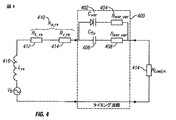
一つの実施例では、キャパシター302は、受信器エア・ループを共振の状態にし、且つ同調を維持するために電圧−同調可能なキャパシターとして働く高Qバラクター・ダイオードと並列する高Qの固定チップ・コンデンサであってもよい。図4はそれ自身が可変キャパシタンス402から形成される同調回路400がその等価直列抵抗(ESR)404と直列に形成された直列共振回路の概要図を示す。固定キャパシターはそのESR 408と直列する406として示される。アンテナの全体オーム抵抗410は全体のアンテナ抵抗412と直列する放射抵抗410として分離されて示される。負荷抵抗414及びインダクタンス416も同じく示される。
In one embodiment,
回路では、シンボルは次の意味を持つ。 In the circuit, the symbols have the following meanings:
V0:ループ・アンテナに亘る誘導電圧
Lrx:ループ・アンテナのインダクタンス
RL_rx、Rr_rx、Ra_rx:受信アンテナ損失(オーム)抵抗、放射抵抗、及び全体のアンテナ抵抗(前の二つの合計)
Cvar、Resr_var:同調バラクターのキャパシタンス及その等価直列抵抗(Equivalent Series Resistance:ESR)
Cfix、Resr_fix:固定キャパシタンス及びその関連ESR
Rload_rx:負荷抵抗
一つの実施例はキャパシタンスの変動及び外部要因による脱調を補うために選択された動作周波数のおよそ±5%の同調範囲を選択する。バラクターの同調範囲は固定キャパシタンス値のおよそ±10%であろう。使用される構成部品は好しくは高Qを持ち、その結果それらは回路の全体のQの劣化をできる限り小さくする。
V 0 : induced voltage across the loop antenna
L rx : loop antenna inductance
R L — rx , R r — rx , R a — rx : Receive antenna loss (ohms) resistance, radiation resistance, and overall antenna resistance (sum of the previous two)
C var , R esr — var : capacitance of tuned varactor and its equivalent series resistance (ESR)
C fix , R esr_fix : Fixed capacitance and its associated ESR
R load — rx : Load resistance
One embodiment selects a tuning range of approximately ± 5% of the selected operating frequency to compensate for capacitance variations and step-out due to external factors. The tuning range of the varactor will be approximately ± 10% of the fixed capacitance value. The components used preferably have a high Q, so that they minimize the overall Q degradation of the circuit as much as possible.
一つの実施例では、同調は送信器においてもっぱら実行される。この実施例では、バラクターは受信器に在る要はなく、そして送信器が受信器のを追跡する。このことは受信器ループのどのくらいの共振周波数がループの近くの環境の変化によって影響を受けるかに依る。逆の構成もまた使用できる。 In one embodiment, tuning is performed exclusively at the transmitter. In this embodiment, the varactor need not be at the receiver, and the transmitter tracks the receiver. This depends on how much resonant frequency of the receiver loop is affected by environmental changes near the loop. The reverse configuration can also be used.
高い周波数において、もしくはより大きなループ寸法に関して、もしくはより多くのループ巻き数に関して、非常に小さなキャパシタンスがループを共振状態にするのに必要とされる。実施例では、他がなくてもバラクターだけ、または固定キャパシタンスだけで使用されるであろう。 Very high capacitance is required to bring the loop into resonance at high frequencies or for larger loop dimensions or for more loop turns. In an embodiment, it would be used only with a varactor or with a fixed capacitance without anything else.
考えられる別の効果は特に高い周波数における、ループの自己共振である。ループ・アンテナ上の巻線間キャパシタンス及び浮遊キャパシタンスが巻線自身のインダクタンスによって共振に至るのでこの効果が生じるであろう。周波数が増加するにつれて、これは減少する。 Another possible effect is loop self-resonance, especially at higher frequencies. This effect will occur because the interwinding capacitance and stray capacitance on the loop antenna will resonate due to the inductance of the winding itself. As the frequency increases, this decreases.
1.3MHzといった低い動作周波数では、より大きな固定キャパシターが必要とされるであろう。例えば、巻回数が5のループ・アンテナによって図3において与えられた寸法を持つループ・アンテナは約3nFの固定キャパシタンスを必要とするであろう。±1パーセント(30pF)のキャパシタンス変動はこれらの型式のキャパシターについて一般的である。示されるように、これは最も利用可能な同調可能キャパシターの同調範囲を越える。従って、低周波において、一つの実施例は送信器だけに適応同調を設置する。 At low operating frequencies such as 1.3 MHz, larger fixed capacitors will be required. For example, a loop antenna having the dimensions given in FIG. 3 by a loop antenna with 5 turns would require a fixed capacitance of about 3 nF. A capacitance variation of ± 1 percent (30 pF) is common for these types of capacitors. As shown, this exceeds the tuning range of the most available tunable capacitors. Thus, at low frequencies, one embodiment installs adaptive tuning only at the transmitter.
動作周波数を増やすか、或いは巻回数を増やすと、固定キャパシタンスのサイズを減少させることを可能にする。さらに大きな巻回数は包装を更に難しくする。従って、多くの巻回数によって、ある形式のアプリケーションの実用的実施は難しくなるであろう。より高い周波数は従ってこの要因が他の場合は制限するであろうアプリケーションにおいてある利益になるであろう。 Increasing the operating frequency or increasing the number of turns makes it possible to reduce the size of the fixed capacitance. Larger turns make packaging more difficult. Thus, a large number of turns may make practical implementation of certain types of applications difficult. Higher frequencies will therefore have some benefit in applications where this factor would otherwise limit.
しかしながら、250MHz以上の周波数では、必要とされる固定キャパシターのサイズは非常に小さく、例えば、N=1に関して1pFの程度であり、そしてさらに多くの巻数ではさらに小さくなる。これらの周波数では、固定キャパシターはある場合には全く除去され、そして非常に小さな同調キャパシターだけが使用される。キャパシター・サイズに関するこの物理的限界はまた或るループ寸法について使用できる周波数に制限を与える。より小さな受信器ループ・サイズはより高い周波数またはより多くのループが使用されることを可能にする。 However, at frequencies above 250 MHz, the required fixed capacitor size is very small, eg, on the order of 1 pF for N = 1, and even smaller with more turns. At these frequencies, the fixed capacitors are totally eliminated in some cases and only very small tuning capacitors are used. This physical limit on capacitor size also limits the frequencies that can be used for certain loop dimensions. A smaller receiver loop size allows higher frequencies or more loops to be used.
低ピコファラッドから低ナノファラッドの範囲のキャパシタンスを持つ典型的な高Q/低ESRは商業的に、例えば、AVX社から入手できる。他に多数のデバイスも使用されるけれども、いくつかの可能で適切なAVXキャパシターの詳細は表3で一覧表になっている。
一般に、Q、ESR及びCは次の数式、
C=1/ωRserQ
によって関係付けられる。
In general, Q, ESR and C are:
C = 1 / ωR ser Q
Related by.
別の実施例はMEMS(微小電気機械式システム)バラクターを使用する。これは電力消費量を減少させる。 Another embodiment uses a MEMS (microelectromechanical system) varactor. This reduces power consumption.
共振における図4の回路は性能を評価するために解析される。最初の方法では、バラクターは主固定キャパシターのサイズの10分の1を固定値キャパシターによって置換えられるであろう。AVXデータは両方のキャパシターのために使用されるであろう。図4の同調回路100は単一のR/Cインピーダンスとしてモデル化される。使用される値は以下である。
The circuit of FIG. 4 at resonance is analyzed to evaluate performance. In the first method, the varactor will be replaced with a fixed value capacitor for one tenth of the size of the main fixed capacitor. AVX data will be used for both capacitors. The
Irxは受信器ループにおける電流である。 I rx is the current in the receiver loop.
Prxは負荷抵抗器における電力である。 P rx is the power in the load resistor.
Cserは固定キャパシター及びバラクターの等価直列キャパシタンスである、そして
Rserは固定キャパシター及びバラクターの等価直列抵抗である
共振では、XL=−Xcであるので、リアクタンスは無視できる。回路における抵抗(真の)損失だけが考慮される。
C ser is the equivalent series capacitance of the fixed capacitor and varactor, and R ser is the equivalent series resistance of the fixed capacitor and varactor. At resonance, XL = −Xc, so the reactance is negligible. Only resistance (true) losses in the circuit are considered.
発明者は同調されたアンテナの抵抗が負荷抵抗に合致されるとき、電力Prxの最大量 が負荷で利用可能であることを見つけた。言い換えれば、最適条件は、
RL_rx+Rr_rx+Rser=Rload_rx
のときである。それらの値は「最適(optimum)」共振の中にまだ留まっている間、20%だけ変動する。
The inventor has found that the maximum amount of power P rx is available at the load when the tuned antenna resistance is matched to the load resistance. In other words, the optimal condition is
R L _ rx + R r _ rx + R ser = R load _ rx
At the time. Their values vary by 20% while still remaining in the “optimum” resonance.
実施例では、従って、送信器回路はそのループが発信源に電力整合される共振ループとしてモデル化される。他の形式、サイズ及び寸法のアンテナが他の実施例では送信器のために使用されるけれども、最大寸法20cm(即ち、10cmの半径r)、1mmの線径及び単回巻(N=1)を持つ典型的なエア・ループ・アンテナが実施例に使用される。 In an embodiment, the transmitter circuit is thus modeled as a resonant loop whose loop is power matched to the source. Although other types, sizes and dimensions of antennas are used for the transmitter in other embodiments, the maximum dimension is 20 cm (ie, a radius r of 10 cm), a wire diameter of 1 mm and a single turn (N = 1) A typical air loop antenna with is used in the embodiment.
一つの実施例では、送信器アンテナは、例えば、家の中のベンチまたはテーブル上に、壁の中に、壁電力口の周りに、ガレージ階にまたはガレージ階の中に、冷蔵庫等の後ろに、等々、垂直に置かれるであろう。計算を単純化するために、図3のように、ループは円であるとみなされるであろう。10cm半径の線直径、1mmの線径を持つ図3の単一線ループの送信アンテナは約840nHのインダクタンスを持つ。異なる周波数はこのアンテナとの共振のための異なるキャパシタンス値を必要とするであろう。例えば、1.3MHzは17.85nFのキャパシターを必要とするであろう、13.56MHzは164.1pFを必要とするであろう、64MHzは7.365pFを必要とするであろう、250MHzは0.483pFを必要とし、そして500MHzは0.121pFを必要とするであろう。 In one embodiment, the transmitter antenna is behind a refrigerator or the like, for example, on a bench or table in a house, in a wall, around a wall power outlet, in the garage floor or in the garage floor. , Etc. would be placed vertically. To simplify the calculation, the loop will be considered a circle, as in FIG. The single-wire loop transmit antenna of FIG. 3 with a 10 cm radius wire diameter and 1 mm wire diameter has an inductance of about 840 nH. Different frequencies will require different capacitance values for resonance with this antenna. For example, 1.3 MHz will require a 17.85 nF capacitor, 13.56 MHz will require 164.1 pF, 64 MHz will require 7.365 pF, 250 MHz is 0 .483 pF and 500 MHz would require 0.121 pF.
いくつかの異なるアンテナがここに実施例として述べられる。実施例の試験のために、アンテナは1.5mm2の銅線で造られ、そして木製の枠(wooden frame)に固定された。 Several different antennas are described here as examples. For the test of the examples, the antenna was made of 1.5 mm 2 copper wire and fixed to a wooden frame.
送信アンテナは0.2mの半径、6回巻、及び3MHzの動作周波数を持つ。整合(matching)は二つの同調可能なキャパシターによって実現される。受信アンテナは0.1mの半径を持つ。電力転送/経路利得を考慮する前に、アンテナは独立に同調され、そして測定された。その結果生じる特性は表6に要約される。
品質因子増加はさらに電力転送を増加させる。例えば、品質因子はマットラブ(Matlab)シミュレーションを使用して増加できる。シミュレーションのために行われた数学的調査は経路利得に関して次の近似式に導く。
但し、
a=ループ半径[m]
b=線経[m]
QUl=無負荷品質因子
x=送信機アンテナと受信器アンテナ間の距離[m]
上記式は実用的なアンテナについてのものを示し、ループ半径は経路利得に対して高影響を与える。
However,
a = loop radius [m]
b = Meridian [m]
Q Ul = no-load quality factor x = distance between transmitter antenna and receiver antenna [m]
The above equation shows that for a practical antenna, where the loop radius has a high effect on the path gain.
第二実施例のアンテナ
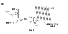
図5はアンテナの第二の実施例を例示する。この実施例は伝送電力502が届けられる結合ループ500間の最大化電力転送を取得する。結合ループは最適化Qを持つ共振器へ放射する。この実施例は二つのキャパシターから作られた結合ネットワークの代わりに共振器として働く結合ループを使用する。これは整合ネットワークを省略することによって損失を減少させる。結合ループとアンテナとの間の結合は理想的な変圧器として概念化できる。
Antenna of Second Embodiment FIG. 5 illustrates a second embodiment of the antenna. This embodiment obtains a maximized power transfer between the
アンテナは線表面を増加させることによって損失抵抗を減少させるために、例えば、銅管等から作られる。その上、表面は銀(Ag)または当分野で周知の別の高伝導度材料で鍍金(めっき)される。この形式の構造体によって、下記でさらに詳細に述べられるように、103の程度の品質因子が達成される。アンテナの共振器部分はまた高品質因子(Q)について最適化される。これは巻回数を増加させ、線の表面を増加させ、そしてアンテナの隔離または取付けによる誘電損失を減少させることによって行われる。 The antenna is made from, for example, a copper tube to reduce the loss resistance by increasing the wire surface. In addition, the surface is plated with silver (Ag) or another high conductivity material well known in the art. With this type of structure, a quality factor on the order of 10 3 is achieved, as will be described in more detail below. The resonator portion of the antenna is also optimized for a high quality factor (Q). This is done by increasing the number of turns, increasing the surface of the wire, and reducing dielectric losses due to antenna isolation or mounting.
アンテナの共振周波数を同調させるために、同調可能なキャパシター504、512は双方のアンテナの底で統合される。そのキャパシターはキャパシターの2枚の平板の間の距離を変えるために3本のねじを使用することによって同調可能な金属平板である。キャパシターはアンテナの自己キャパシタンス(self-capacitance:CS)を支配する。表6Aはこれらのアンテナの特性を例示する。
アンテナの典型的な実施例は6.0mmの外径を持つ銅管から形成される。その表面は銀めっきされる。これは銅を腐食から保護し、そして表面の伝導率を僅かだが増加させる。 An exemplary embodiment of the antenna is formed from a copper tube having an outer diameter of 6.0 mm. Its surface is silver plated. This protects the copper from corrosion and slightly increases the surface conductivity.
8mmの同調可能なキャパシターの典型的な平板−距離によって、その結果生じる計算共振周波数は14.4MHzである。 With a typical plate-distance of an 8 mm tunable capacitor, the resulting calculated resonant frequency is 14.4 MHz.
1300のQを使用すると、経路利得は1mで約−10dBであり、それは0.1の因子に対応する。言い換えれば、10ワットの伝送電力が受信器において1Wを受取るために使用されるということである。 Using a Q of 1300, the path gain is about -10 dB at 1 m, which corresponds to a factor of 0.1. In other words, 10 watts of transmitted power is used to receive 1 W at the receiver.
システムはアンテナの無負荷Q(QUl)の周辺で定義されなければならず、
で開始する。TxまたはRxアンテナのいずれかの全損失抵抗は、
によって定義できる。共振のときは、それは
Pin=I2R 式 1−3
と書くことができる。
Can be defined by At resonance, it is
P in = I 2 R Formula 1-3
Can be written.
TX−アンテナにおいてその結果生じる電流はすぐに
I=(Pin/R)1/2 式 1−4
によって特定される。式 1−2を使用すると、電流は
I = (P in / R) 1/2 formula 1-4
Specified by. Using Equation 1-2, the current is
として書き直すことができる。距離xで電流によってTX−アンテナに生成されるH−場の大きさは、
であり、そして電圧、
をRX−アンテナに誘起する。パラメータrAは半径で、Nはループ・アンテナの巻回数である。利用可能な出力電力Poutはすぐに、
によって計算できる。最後に、経路利得は、
として定義される。さらに式 1−10及び式 1−9の挙動を単純化し、且つ理解するために、L及びCのモデルが必要とされる。キャパシタンスは共振周波数
に亘って簡単に定義できる。誘導率については、実験式がこのシステムに使用されるアンテナの型式に関して最も正確であることが見出された。
パラメータIAはアンテナの幅である。 Parameters I A is the width of the antenna.
アンテナ間の距離(separation)xがアンテナの半径rAに比べて大きい(x>rA)という仮定のもとで、そして式 1−11及び式 1−12によって、式 1−10は、
として書くことができる。 Can be written as
式 1−13における括弧内の項は線形経路利得である。これらのパラメータは品質因子に間接的に含まれるが、この線形経路利得は周波数及び巻回数の直接関数ではない。ループ半径がループ長lAよりはるかに大きければ、経路利得はループ半径rA 6におおよそ比例する。それはアンテナ間の距離xに逆比例する。それはまた品質因子QUl 2に比例する。 The term in parentheses in Equation 1-13 is the linear path gain. Although these parameters are indirectly included in the quality factor, this linear path gain is not a direct function of frequency and number of turns. If the loop radius is much larger than the loop length l A , the path gain is roughly proportional to the loop radius r A 6 . It is inversely proportional to the distance x between the antennas. It is also proportional to the quality factor Q Ul 2 .
あるアンテナ寸法について、品質因子が増加するにつれて、経路利得は改善される。これはシミュレーションを通して実施例において認証される。前述の数式は異なるサイズ及び品質因子を持つアンテナを試験するためにマットラブ(商標名)を用いてシミュレーションされた。次のパラメータ集合はスクリプトを走らせるために定義された。 For some antenna dimensions, the path gain improves as the quality factor increases. This is verified in the embodiment through simulation. The above formula was simulated using a Matlab ™ to test antennas with different sizes and quality factors. The following parameter set was defined to run the script.
% パラメータ定義
Q=1000;% 目標無負荷品質因子[1]
N=7;% 巻回数[1]
r_loop=85e−3;% ループ・アンテナの半径[m]
r_wire=3e−3;% 線の半径[m]
pitch=12e−3;% 二つの巻線間の距離(中心から中心まで)[m]
freq=13.0e6;% システム周波数[Hz]
dist=1:0.1:3;% アンテナの距離[m]
P_in=1;% 入力電力[W]
その結果生じるシミュレーションは式 1−13において項x6によって引起こされる1桁当たり−60dBの経路利得変動を示した。Qが、例えば、1000から2000へ2倍されるならば、 経路利得は6dBだけ増加する。距離が2倍にされるならば、経路利得は18dBだけ減少する。典型的な定義パラメータはTX−及びRX−アンテナの双方に有効であり、従ってパラメータについて最適なアンテナの形成を支援しうる。
% Parameter definition Q = 1000;% Target no-load quality factor [1]
N = 7;% number of turns [1]
r_loop = 85e−3;% Loop antenna radius [m]
r_wire = 3e-3;% Radius of line [m]
pitch = 12e-3;% Distance between two windings (from center to center) [m]
freq = 13.0e6;% system frequency [Hz]
dist = 1: 0.1: 3;% Antenna distance [m]
P_in = 1;% Input power [W]
The resulting simulation showed path gain variation of -
シミュレーションはまた無効電圧(reactive voltages)を計算する。インダクタンス及びキャパシタンスで発生する無効電圧は品質因子に直接比例し、そして式1−14において示された伝送電力の平方根に比例する。
双方の無効電圧は実用的実施では非常に高くなるであろうし、従ってそれらの電圧の計画を立てることはさらに重要になる。1000のQ及び10Wの伝送電力によって、 その電圧は2.7kVである。平板キャパシターが0.01mの平板距離で使用されるならば、その結果生じる場の強さは270kV/mである。これらの高電圧に耐えうるキャパシターが重要になる。例えば、2000Vまたは3000Vまたはそれより高い耐電圧キャパシターを使用することが必要である。この型式のシステムが過去に適切に動作しなかった少なくとも一つの理由はそれらが実際に存在した無効電圧の量について適切に大きさ合わせされなかったことであると考えられている。実際、2KV以上の予期せざる高電圧ははるかに小さな電圧が伝送されつつあるときでもこれらの無効電圧の一部として見出される。この予期せざる高電圧は回路部品によって処理される必要がある。 Both reactive voltages will be very high in practical implementations, so planning for those voltages becomes even more important. With a Q of 1000 and a transmission power of 10 W, the voltage is 2.7 kV. If a plate capacitor is used at a plate distance of 0.01 m, the resulting field strength is 270 kV / m. Capacitors that can withstand these high voltages are important. For example, it is necessary to use a withstand voltage capacitor of 2000V or 3000V or higher. It is believed that at least one reason why this type of system has not worked properly in the past was that they were not properly scaled for the amount of reactive voltage that actually existed. In fact, unexpectedly high voltages above 2 KV are found as part of these reactive voltages even when much smaller voltages are being transmitted. This unexpected high voltage needs to be handled by the circuit components.
アンテナ設計過程の主要な焦点は品質因子を最適化することにあるので、品質因子の定義がまた重要になる。従って、下記にQの徹底解析を述べる。 Since the main focus of the antenna design process is to optimize quality factors, the definition of quality factors is also important. Therefore, a thorough analysis of Q is described below.
品質因子に関する基本方程式は上記の式 1−1によって与えられる。
図6はいくつかの異なる周波数について周波数に対するQのプロットを例示する。 FIG. 6 illustrates a plot of Q versus frequency for several different frequencies.
ここで留意すべきはLとCの割合がこの数式において重要であることである。ある共振周波数について、無限の数の可能なL−Cの組合せがある。しかしながら、インダクタンスLがキャパシタンス(capacitance)と比べてできる限り高いとき、より高いQが取得される。 Note that the ratio of L and C is important in this equation. There are an infinite number of possible LC combinations for a given resonant frequency. However, a higher Q is obtained when the inductance L is as high as possible compared to the capacitance.
品質因子はまたRに逆比例する。この抵抗は損失抵抗(Rl)と放射抵抗(Rr)から成る。双方は品質因子を増加させるために最小化されなければならない。 The quality factor is also inversely proportional to R. This resistance is composed of a loss resistance (R 1 ) and a radiation resistance (R r ). Both must be minimized to increase the quality factor.
損失抵抗はアンテナを作るために使用される材料に依存し、そしてシステムに使用される周波数の表皮効果に起因する。良い表皮効果を持つ高伝導性の材料が望ましい。 The loss resistance depends on the material used to make the antenna and is due to the skin effect of the frequency used in the system. A highly conductive material with good skin effect is desirable.
高い共振周波数は損失を増加させ、従って品質因子を減少させる。こういう理由で、図6の曲線は周波数−目盛の上端で減少する。しかしながら、より低い共振周波数はキャパシタンスを増大させることによって取得される。これはL/C比率を減少させ、そして、Lは周波数と無関係であるので、これはQを減少させる。従って、図6の曲線は周波数−目盛の上端と下端の両方でQが減少し、或るアンテナ寸法について29MHzの周波数の周辺で理想的な品質因子を作ることを示す。 A high resonant frequency increases losses and thus decreases quality factors. For this reason, the curve in FIG. 6 decreases at the top of the frequency-scale. However, a lower resonant frequency is obtained by increasing the capacitance. This reduces the L / C ratio and this reduces Q since L is independent of frequency. Thus, the curve in FIG. 6 shows that Q decreases at both the top and bottom of the frequency-scale, creating an ideal quality factor around a frequency of 29 MHz for some antenna dimensions.
これは各アンテナ配置について理想的な周波数または周波数範囲を示す。 This represents the ideal frequency or frequency range for each antenna arrangement.
ここに述べた試験の間に使用される13MHzの共振周波数はこの理想的周波数以下である。これはアンテナの共振器以下の自己共振(それは同調可能なキャパシターなしの共振周波数である)が35MHzの周辺にあるからである。共振器が同調可能なキャパシターなしでこの周波数で使用されるならば、すぐ近くの対象(objects)に対するアンテナの感度が重要になる。 The resonant frequency of 13 MHz used during the tests described here is below this ideal frequency. This is because the sub-resonant self-resonance of the antenna (which is the resonant frequency without the tunable capacitor) is around 35 MHz. If the resonator is used at this frequency without a tunable capacitor, the sensitivity of the antenna to nearby objects becomes important.
実施例はこの影響を最小化し、そしてそれと同時に共振周波数を変更することを可能にする。共振器の自己キャパシタンス(self-capacitance)を支配する値の同調可能なキャパシタンスはこの目的のために使用される。付加キャパシタンスはアンテナの共振周波数を下げる。 The embodiment minimizes this effect and at the same time makes it possible to change the resonant frequency. A tunable capacitance whose value governs the self-capacitance of the resonator is used for this purpose. The additional capacitance lowers the resonant frequency of the antenna.
品質因子は一般的に直接測定することができない。その代りに、定義
Q=ω0/Δω 式 2−1
が出発点として使用され、ここでω0は共振周波数の中心、そしてΔωは3dB−帯域幅に対応する。従ってQは二つのパラメータω0及びΔωを測定することによって求められる。
Quality factors generally cannot be measured directly. Instead, define
Q = ω 0 / Δω Formula 2-1
Is used as a starting point, where ω 0 corresponds to the center of the resonant frequency and Δω corresponds to 3 dB-bandwidth. Therefore, Q is determined by measuring two parameters ω 0 and Δω.
3dB−帯域幅は次のように求められる。一次直列RLC−回路のインピーダンスZは
Z=R+jωL+1/(jωC) 式 2−2
によって与えられる。
The 3 dB-bandwidth is determined as follows. The impedance Z of the primary series RLC-circuit is
Z = R + jωL + 1 / (jωC) Equation 2-2
Given by.
ω0=1/(LC)1/2 式 2−3
及び
Q=(1/R)・(L/C)1/2 式 2−4
を用いて、インダクタンスL及びキャパシタンスCはQ及びω0に関して次のように書くことができる。
ω 0 = 1 / (LC) 1/2 formula 2-3
as well as
Q = (1 / R) · (L / C) 1/2 formula 2-4
, Inductance L and capacitance C can be written in terms of Q and ω 0 as follows:
L= QR/ω0 式 2−5
C= 1/(QR・ω0) 式 2−6
式 2−5及び式 2−6が式 2−2で使用されるならば、インピーダンスは
Z=R+j・QR(ω/ω0―ω0/ω) 式 2−7
によって表される。品質因子Qはまた(式 2−1と同様に)帯域幅を定義するために使用される。
L = QR / ω formula 0 2-5
C = 1 / (QR · ω 0 ) Formula 2-6
If Equation 2-5 and Equation 2-6 are used in Equation 2-2, the impedance is
Z = R + j · QR (ω / ω 0 −ω 0 / ω) Equation 2-7
Represented by The quality factor Q is also used to define the bandwidth (similar to Equation 2-1).
Δω/2=ω0/2Q 式 2−8
インピーダンス位相はZの虚数部分をZの実数部分で除算した逆正接(inverse tangent)によって与えられる。この除算では、Rは相殺する。その上式 2−8が使用され、そして関数が上部切断周波数で評価されるならば、位相は
Impedance phase is given by the arctangent of dividing the imaginary part of Z in the real part of Z (inverse tangent). In this division, R cancels. Furthermore, if equations 2-8 are used and the function is evaluated at the upper cutting frequency, the phase is
によって与えられる。括弧の中の式が単純化されるならば、位相はQのみに依存するようになる。
Qが増加するならば、括弧の中の関数は1になる傾向がある。
式 2−11からの結果はZの虚数部がZの実数部に等しいことを意味する90度の角度に対応する。二つの点はそこでネットワーク・アナライザーによって求められ、そして式 2−1がQを計算するために使用できる。従って、この枠組を使用すると、そのようなアンテナのQ値が実際に決定できる。 The result from Equation 2-11 corresponds to an angle of 90 degrees meaning that the imaginary part of Z is equal to the real part of Z. The two points are then determined by the network analyzer and Equation 2-1 can be used to calculate Q. Therefore, using this framework, the Q value of such an antenna can actually be determined.
アンテナの第二の実施例は図7に示される。結合ループ700はアンテナ710の主要部から約0.1m離れて置かれる。平板キャパシターは二つの銅板721、722の間で形成される。ねじ723、724、725はポリイミドのような容量的に不活性な材料で形成される。これらのねじは同調可能なキャパシター720によって提供されるキャパシタンスを調整し、そしてアンテナの共振周波数を同様に調整するために使用される。
A second embodiment of the antenna is shown in FIG. The
ガラス体730または他の誘電体はアンテナの下方の障害物による損失を最小化するためにアンテナの下方にある。
A
さらに、上で述べたように、表面伝導はQを最大化するために重要である。銀めっきまたは他の非腐食性材料が腐食から銅を保護するために適用される。 Furthermore, as mentioned above, surface conduction is important for maximizing Q. Silver plating or other non-corrosive material is applied to protect the copper from corrosion.
結合ループ700は同じ銅管材料で形成されるが、わずか1回巻で、且つアンテナの直径の約半分である。結合ループは50W整合を得るためにアンテナから約0.1m離れたところに置かれる。
下記にアンテナ部品の共振周波数がどのように決定できるかを説明する。次の数式では、Lは共振器自身のインダクタンス、Csは共振器の自己キャパシタンス、そしてCTは共振器と関連する同調可能なキャパシター、Rrは放射抵抗、Rlは共振器の損失抵抗である。
但し、
rA=ループ半径
N=巻回数
IA=アンテナの長さ
μ0=1.2566・10−6。
r A = loop radius N = number of turns I A = antenna length μ 0 = 1.2556 · 10 −6 .
p=アンテナのピッチ、巻線の直径を加えた二つの巻線間の距離に対応する
ε0=8.8542・10−12
注:この定式の導出に関して[GRA]を見よ。
Note: See [GRA] for the derivation of this formula.
但し、
A=平板キャパシターの面積
d=平板間の距離
注:周縁処理が無視されているので、これは近似式である。実際のキャパシタンスは計算値より高い。
A = area of plate capacitor d = distance between plates Note: This is an approximate expression because the edge treatment is ignored. The actual capacitance is higher than the calculated value.
但し、
λ=周波数f0における波長。
λ = wavelength at frequency f 0 .
但し、
σ=アンテナに使用される金属の伝導率、45・106S/mが計算に使用される
rW=銅管の半径
表8はTアンテナ・パラメータの現在の値に取得された値を示す。
σ = conductivity of the metal used for the antenna, 45 · 10 6 S / m is used in the calculation r W = radius of the copper tube Table 8 shows the values obtained for the current values of the T antenna parameters .
経路利得−測定のための典型的な試験配置は実際の値を取得するために実行される。この測定は同軸遮蔽(coaxial shields)上及び送電線(power lines)上の電力転送を回避するために送信器を受信器から切り離す。信号発生器及び電池駆動スペクトル・アナライザーは各々送信器及び受信器側にそれぞれ使用される。 Path gain—A typical test arrangement for measurement is performed to obtain actual values. This measurement decouples the transmitter from the receiver to avoid power transfer on coaxial shields and power lines. A signal generator and a battery-powered spectrum analyzer are used on the transmitter and receiver sides, respectively.
整合の品質を測定するために、送信アンテナから戻るエネルギーが指向性結合器(directional coupler)を通して接続された電力計で測定される。指向性結合器の指向性結合ポートは50W負荷で終端される。測定の間、整合は少なくとも20dBであった。整合はアンテナと結合ループとの間の距離を調整することによって変えることができる。 To measure the quality of the match, the energy returning from the transmit antenna is measured with a wattmeter connected through a directional coupler. The directional coupling port of the directional coupler is terminated with a 50 W load. During the measurement, the match was at least 20 dB. The matching can be changed by adjusting the distance between the antenna and the coupling loop.
受信器側には、スペクトル・アナライザーが受信アンテナに直接接続される。 On the receiver side, a spectrum analyzer is directly connected to the receiving antenna.
同じ共振周波数が双方のアンテナに使用される。脱調(detuning)は電力転送の劇的な減少をもたらす。受信アンテナは同調補助(tuning aid)、例えば、アンテナの同調可能キャパシターに選択的に挿入可能なテフロン(登録商標)棒(Teflon(登録商標) bar)を使用するか(それは約40kHzの共振変化(resonance-shift)をもたらす)、或いは以前に述べたように調節可能なキャパシターを使用する。測定された各距離について、受信アンテナは利用可能な最大電力を受取るように同調される。送信アンテナは信号発生器の周波数を僅かに調整することによって同調される。 The same resonant frequency is used for both antennas. Detuning results in a dramatic reduction in power transfer. The receiving antenna uses a tuning aid, for example, a Teflon bar that can be selectively inserted into the antenna's tunable capacitor (which has a resonant change of about 40 kHz ( resonance-shift)), or use adjustable capacitors as previously described. For each measured distance, the receive antenna is tuned to receive the maximum available power. The transmit antenna is tuned by slightly adjusting the frequency of the signal generator.
表9は測定された経路利得の結果を示す。
さらに、無効電圧は容易に数kVを越えることがあるので、キャパシターの適切なサイズ化の決定を可能にするために、その無効電圧を決定するためアンテナ原型を試験することは有用である。電気的に分離されたシステムが使用される。信号発生器からの源信号は50dB RF増幅器によって増幅される。20dB仲介減衰器(attenuator in-between)はTXアンテナ上で利用可能な電力を制限するために使用される。 Furthermore, since the reactive voltage can easily exceed several kV, it is useful to test the antenna prototype to determine its reactive voltage to allow determination of proper sizing of the capacitor. An electrically isolated system is used. The source signal from the signal generator is amplified by a 50 dB RF amplifier. A 20 dB attenuator in-between is used to limit the power available on the TX antenna.
増幅器の後の3dB減衰器は不整合アンテナの場合に増幅器を保護するために使用される。整合の品質を測定するために、電力計がアンテナから戻るエネルギーを表すために使用される。受信器側で、小さな電球(50W/3W)が受信電力を示すために使用される。同調及び整合は同調補助を使用することによって、信号発生器の周波数を変えることによって、そしてアンテナと結合ループとの間の距離を変えることによって実現された。 A 3 dB attenuator after the amplifier is used to protect the amplifier in the case of a mismatched antenna. A power meter is used to represent the energy returning from the antenna to measure the quality of the match. On the receiver side, a small bulb (50W / 3W) is used to indicate the received power. Tuning and matching has been achieved by using tuning aids, by changing the frequency of the signal generator, and by changing the distance between the antenna and the coupling loop.
結果は表10に要約される。
一つの実施例では、すぐ近くの対象物または人間に対する感度が、例えば、浮遊キャパシタンスによる共振周波数の偏位を引起こす。これはアンテナの周辺に配置された遮蔽物(shield)、例えば、スロット状遮蔽物または他の遮蔽物によって緩和される。 In one embodiment, the sensitivity to a nearby object or person causes a resonance frequency excursion due to, for example, stray capacitance. This is mitigated by a shield placed around the antenna, for example a slot shield or other shield.
別の実施例では、高誘電性強度及び非常に良い隔離能力を持つ一片の雲母が上に述べたポリイミドねじの代わりに使用される。これはまた品質因子を引上げる。比較的少ないエネルギーは高分子体(polymer)と比べて雲母によって吸収されることが要求提案である。 In another embodiment, a piece of mica with high dielectric strength and very good isolation capability is used in place of the polyimide screw described above. This also raises the quality factor. It is a proposed proposal that relatively little energy is absorbed by the mica compared to the polymer.
別の構成では、雲母またはテフロンの非常な薄片がキャパシターを保持し、そして伝送電力を制限するために使用される。 In another configuration, a very thin piece of mica or Teflon is used to hold the capacitor and limit the transmitted power.
Qと帯域幅の間には二律背反がある。高品質因子のために、典型的な第二のアンテナの帯域幅は幾分狭く、例えば、13MHzの共振周波数で約9kHzである。双方のアンテナはほとんど正確に同じ共振周波数で働かねばならないので、これはある同調要求が生じる。従って、別の実施例では、上で述べた近付く対象物へのアンテナ感度は上で述べた遮蔽物を用いて減少される。電子同調回路は同期を保つためにアンテナ回路を自動的に調整するのに使用される。脱調の問題はQが非常に狭いこのようなシステムにおいて特に重要になる。この狭いQは狭い帯域幅を意味し、それは同調が緊密であることを要求する。 There is a trade-off between Q and bandwidth. Due to the high quality factor, the bandwidth of a typical second antenna is somewhat narrow, for example about 9 kHz with a resonance frequency of 13 MHz. This creates certain tuning requirements because both antennas must work at almost exactly the same resonant frequency. Thus, in another embodiment, the antenna sensitivity to the approaching object described above is reduced using the shielding described above. The electronic tuning circuit is used to automatically adjust the antenna circuit to maintain synchronization. The step-out problem becomes particularly important in such systems where the Q is very narrow. This narrow Q means a narrow bandwidth, which requires tight tuning.
Qへの様々な外部または設計要素の影響をさらに評価するために、実験装置の様々な形態が、例えば、アンテナの下のガラス体、キャパシターの中の雲母片、結合ループの損失、及びアンテナの近接場内の全ての対象物の損失を含めて考慮される。 In order to further evaluate the effect of various external or design factors on Q, various configurations of the experimental apparatus include, for example, the glass body under the antenna, the mica fragment in the capacitor, the loss of the coupling loop, and the antenna This includes the loss of all objects in the near field.
これらの因子を評価するために、アンテナの環境はできる限り理想的でなければならない。従って、典型的アンテナは2本の細いナイロン紐によって吊るされた。二つの結合ループは反射(S 11)の代わりに伝送(S 12/S 21)を測定するために使用される。結合ループは臨界以下の結合(undercritical coupling)を達成するためにアンテナから約0.6m離れてアンテナの両側に置かれた。即ち、等しい量の電力が共振器自身におけると同様に外部の回路において散逸されるとき、その結合は臨界的である(そしてアンテナは整合される)と云われる。臨界以下の結合はより多くの電力が外部の回路より共振器において散逸されることを意味し、一方、臨界過度の結合はより多くの電力が共振器より外部の回路において失われることを意味する。 In order to evaluate these factors, the antenna environment should be as ideal as possible. Thus, a typical antenna was suspended by two thin nylon strings. Two coupled loops are used to measure transmission (S 12 / S 21) instead of reflection (S 11). The coupling loop was placed on both sides of the antenna about 0.6 m away from the antenna to achieve undercritical coupling. That is, when equal amounts of power are dissipated in the external circuit as well as in the resonator itself, the coupling is said to be critical (and the antenna is matched). Subcritical coupling means that more power is dissipated in the resonator than external circuitry, while supercritical coupling means more power is lost in the circuitry external to the resonator. .
この実施例の理論的に予想されるQは2877である。実現された2263のQは理論値の78.6%である。理論値はこの試験においてほとんど到達された。しかしながら、より高いQはその環境によってアンテナがより影響を受けやすくすることがまた注目された。このように、実際上、Qは恐らく常に理論値以下であろう。 The theoretically expected Q for this example is 2877. The realized Q of 2263 is 78.6% of the theoretical value. The theoretical value was almost reached in this test. However, it was also noted that higher Q makes the antenna more susceptible to its environment. Thus, in practice, Q will probably always be less than the theoretical value.
第二の測定は品質因子の別の特徴を示した。負荷品質因子QLは共振器が臨界的に結合される状態のもとでは無負荷品質因子(QUl)の半分である。 The second measurement showed another characteristic of the quality factor. The load quality factor Q L is half of the no-load quality factor (Q Ul ) under the condition that the resonator is critically coupled.
前述の送信器及び受信器装置(例えば、アンテナ及び任意の電子または電気部品)はまた送受信器(即ち、電力を伝送し、且つ受取るように適応されたデバイス)として別の実施例では結合される。これは例えば共通の形状要素(例えば、その中に配置された送信及び受信アンテナの両方及び回路を持つ単一ユニットまたは「箱(box)」)を含む。さらに、そのデバイスは受信アンテナを介して一つの源(source)からエネルギーを受取り、そしてそこで送信アンテナを使用して受取電力を他の源へ(または同じ源のもとへ)受取電力を伝送するための中継器として使われる。これらのイベント(伝送及び受取)は同じ時間に、或いは相互と比較して遅れて発生する。値は分極、強度、配置、相対的な間隔及び配列、及び送信及び受信アンテナと関連する他の因子によって修正でき、或いは、例えば、周波数分割またはFDMAのようないくつかの周知の多元アクセス手法に従って同じく行われる(例えば、そこでは第一のアンテナ(送信器または受信器)の共振周波数は第二のアンテナ(送信器または受信器)のそれと異なるか、或いは分離される)。なお別の選択肢として、二つのアンテナは同じか、または異なる周波数を使用し、そしてそれらの動作に関して時分割されるか、或いはスロット化される(例えば、TDMA)。 The aforementioned transmitter and receiver devices (eg, antennas and any electronic or electrical components) are also combined in another embodiment as a transceiver (ie, a device adapted to transmit and receive power). . This includes, for example, common shape elements (eg, a single unit or “box” having both transmit and receive antennas and circuitry disposed therein). In addition, the device receives energy from one source via a receive antenna and then uses the transmit antenna to transmit received power to another source (or to the same source). Used as a repeater for These events (transmission and reception) occur at the same time or later than each other. The value can be modified by polarization, strength, placement, relative spacing and alignment, and other factors associated with transmit and receive antennas, or according to some well-known multiple access techniques such as frequency division or FDMA, for example. The same is done (for example, where the resonant frequency of the first antenna (transmitter or receiver) is different from or separate from that of the second antenna (transmitter or receiver)). As yet another option, the two antennas use the same or different frequencies and are time-shared or slotted (eg, TDMA) for their operation.
別のこれに代るものでは、「CSMA」のような方法が(衝突検出有り、または無しのいずれでも)使用され、例えば一つのデバイスが他の活動を積極的または受動的に検出または感知し、そしてそれに応じてその挙動を調整する場合には、そのような一つの実施例では、送信器は、送信する前に、受信器の状態(例えば、共振しているか、電流を生成しているかどうか、等々)を検出し、そしてこれを伝送のための通門基準として使用する。 In another alternative, a method such as “CSMA” is used (with or without collision detection), for example, one device detects or senses other activities actively or passively. , And adjusting its behavior accordingly, in one such embodiment, the transmitter may be in a state of the receiver (eg, resonating or generating current) before transmitting. Detection, etc.) and use this as the gateway reference for transmission.
別の実施例は「共振周波数ホッピング」方法を使用し、そこでは例えば、レイリー(Rayleigh)またはアンテナ・ダイバシティ・フェージングまたは他のそのような問題を打破或いは緩和する、多元アクセスまたは他の目標(aims)が共振周波数を時間の関数として定期的または確定的または疑似乱数的にホッピングすることによって達成される。例えば、送信器及び受信器はそれらが同期を維持することを可能にする一般のホップ系列を相互に生成するために対応する決定論的アルゴリズムを「シード(seed)」する。代りに、「帯域内(in-band)」(例えば、変調電力信号)信号方式は送信器から受信器へ前もって(またはそれは続けながら)ホップ系列、例えば、「私は次の区間に周波数Xへ、そしてその後周波数X+Yへ、・・・ホップするであろう」、等々を伝送するために使用される。個別の低電力送信器(例えば、RFまたはBluetooth(登録商標))は特定の情報に同期させるために使用できる。クロック情報はまた類似の方法で送られる。 Another embodiment uses a “resonant frequency hopping” method, for example, multiple access or other objectives that overcome or mitigate Rayleigh or antenna diversity fading or other such problems. ) Is achieved by hopping the resonant frequency as a function of time periodically or deterministically or pseudo-randomly. For example, the transmitter and receiver “seed” the corresponding deterministic algorithm to generate each other a common hop sequence that allows them to remain synchronized. Instead, an “in-band” (eg, modulated power signal) signaling is a hop sequence from the transmitter to the receiver in advance (or while it is), eg, “I go to frequency X in the next interval. , And then to the frequency X + Y,... Will hop, etc. ”and so on. A separate low power transmitter (eg, RF or Bluetooth®) can be used to synchronize to specific information. Clock information is also sent in a similar manner.
別の実施例では、受動的な「衝突検出(collision detection)」またはCD手法が、例えば、送信器が伝送を試みているところで使用され、そして干渉動作がそれと同時に発生しているかどうかを判定する。例えば、その判定は共振周波数、伝送効率、受信器からのフィードバック、または他のいくつかの検出を検出することによるものである。この干渉動作は受信器の動作、寄生または浮遊キャパシタンス効果、同調の損失、または他の同様の影響によって引起こされる。 In another embodiment, a passive “collision detection” or CD approach is used, for example, where the transmitter is attempting to transmit and determine if interference activity is occurring simultaneously. . For example, the determination may be by detecting the resonant frequency, transmission efficiency, feedback from the receiver, or some other detection. This interference behavior is caused by receiver behavior, parasitic or stray capacitance effects, loss of tuning, or other similar effects.
送信器は問題を回避するためにその点で行動をとる。 The transmitter takes action at that point to avoid problems.
実施例では、干渉は一般的に一時的なものであるので、送信器は進行中の伝送を終了させ、そして後の時間に再試行する。この一つの例は反衝突アルゴリズムによる無作為バックオフによる。一つの実施例は伝送された電力が電池のような貯蔵部に蓄えられるのを可能にする。このために、デバイスにおいて電力伝送は一時的に止めることができる、一方、電力を供給されるデバイスがなお動作するのを可能にする。 In an embodiment, the interference is generally transient, so the transmitter terminates the ongoing transmission and tries again at a later time. One example of this is due to random backoff by the anti-collision algorithm. One embodiment allows the transmitted power to be stored in a storage such as a battery. Because of this, power transmission in the device can be temporarily stopped, while still allowing the powered device to operate.
送信器は干渉を緩和するためにそれ自身を異なる共振周波数に同調するか、そして/または同調するか、そうでなければ受信器の動作を変えることを試みることができる。 The transmitter can tune itself to a different resonant frequency to mitigate interference and / or tune it or otherwise attempt to change the operation of the receiver.
別の選択肢はエネルギー転送速度を増加させるために利得を増加させることである。これはいわば干渉を「爆破する(blast through)」ように動作する。 Another option is to increase the gain to increase the energy transfer rate. This works in a way to “blast through” the interference.
送信器及び/受信器の偏り(polarization)または方位(orientation)を調整するシステムは、例えばアンテナの位置を物理的に変更するモーター駆動または同様の機構を介して、使用できる。 A system that adjusts the polarization or orientation of the transmitter and / or receiver can be used, for example, via a motorized or similar mechanism that physically changes the position of the antenna.
前述の任意の組合せが代りに使用できる。これらの特徴は送信器及び/または受信器基盤において、または送信器及び受信器の間の連携または協調において実施できる。 Any combination of the foregoing can be used instead. These features can be implemented in the transmitter and / or receiver infrastructure or in coordination or coordination between the transmitter and receiver.
別の実施例は受信器によって決定された電力転送のレベルまたは速度(rate)に関係するデバイスの間の信号通信情報を使用する(例えば、「ここに私が実際に受取っているものがある。従って、あなたはあなた自身を送信器に同調するためにあなたが実際に送っているものとこれを比較することができる」)。さらに、前述の多元アクセス手法はこの方法、例えば、通信チャネルを経由して送信器に戻り伝送された電力を受取った受信器における落差に基づくバックオフまたはCDで実施できる。 Another embodiment uses signaling information between devices that is related to the level or rate of power transfer determined by the receiver (eg, here is what I have actually received. So you can compare this to what you are actually sending to tune yourself to the transmitter "). Furthermore, the multiple access approach described above can be implemented in this way, for example, back-off or CD based on a drop in the receiver that has received the power transmitted back to the transmitter via the communication channel.
さらに別の代替実施例として、多数の送信器及び/または受信器が使用され、そして前述の特徴が多数の送信器(及び/または受信器)の間と同様に実施される。例えば、FDMA、TDMA、CSMAまたはCD技術が二つの潜在的に対立する送信器の間と同様に適用される。 As yet another alternative, multiple transmitters and / or receivers are used, and the features described above are implemented as well as between multiple transmitters (and / or receivers). For example, FDMA, TDMA, CSMA or CD technology applies as well as between two potentially opposing transmitters.
前述の機能は電気または電子部品レベルで、例えば、簡単なゲート論理回路または個別部品から高集積回路までの何かとして実施される同等品を介して、例えば、マイクロ−コントローラーまたはディジタル・プロセッサー上で働くコンピューター・プログラムまたはアプリケーションとして、手作業で、IC上で処理されるファームウェアを介して、または適用できる程度にハードウェア(例えば、電子機械チューナー、モーター、等々)において実施される。 The aforementioned functions are at the electrical or electronic component level, for example, through simple gate logic or equivalents implemented as anything from discrete components to highly integrated circuits, for example on a micro-controller or digital processor. As a working computer program or application, it is implemented manually, through firmware processed on an IC, or in hardware to the extent applicable (eg, electromechanical tuner, motor, etc.).
さらに、現在の出願は環境特性によって一つ以上のアンテナまたは回路パラメータのある動的変更または変化を意図している。例えば、これはアンテナ特性を変更する。変更される特性は電力信号処理、濾過(filtration)、変調、等といった電気または電子処理と同様に、同調キャパシタンス、抵抗値、ループまたはコイルの半径を含み、それらの特性は、例えば、アンテナを形成するのに使用される材料の伸長または収縮を生じる熱効果を介し、それによってその実効半径、それに近接するアンテナまたは部品の性質を変更する(例えば、特定の電場または磁場を選択的に適用することによって、材料または部品内の双極子(dipoles)の整列が選択的に変更され、それによってアンテナに影響を与える)。 Furthermore, the current application contemplates some dynamic modification or change of one or more antennas or circuit parameters depending on environmental characteristics. For example, this changes the antenna characteristics. The characteristics to be modified include tuning capacitance, resistance values, loop or coil radii, as well as electrical or electronic processing such as power signal processing, filtration, modulation, etc. These characteristics form, for example, an antenna Through the thermal effects that cause the material used to stretch or contract, thereby changing its effective radius, the nature of the antenna or component adjacent to it (eg, selectively applying a particular electric or magnetic field) Selectively alters the alignment of dipoles within the material or part, thereby affecting the antenna).
例えば、一つの実施例では、送信器の(主として)磁場は電力と共に、情報を転送するために情報によって変調され、または伝えられる。 For example, in one embodiment, the transmitter's (primarily) magnetic field, along with power, is modulated or transmitted by information to transfer information.
別の実施例では、この情報は受信器と送信器との間の制御信号方式を含み、それによって任意の個別のデータまたは通信回線を取り除く(そしてここからシステムを単純化し、且つそれをさらに強固にする)。例えば、送信器は、例えば、振幅変調、位相変調、側波帯または周波数変調、例えば、データ「0」または「1」を符号化するGMSKまたは側波帯上下偏移、疑似ノイズ変調、または他の技術を介して、伝送狭帯域信号を時間の関数として変調する。これは相互アリア(alia)送信器パラメータ(例えば、電力転送を最適化するために受信器が送信器に良く「自動追随する(lock on)」ことを他の場合に可能にする共振周波数、偏極、等々)に関する情報の転送を可能にする。デューティ・サイクル、クロック、またはタイミング情報もまた参照の時間フレーム等に同期させるために、例えば、送信器が作動するであろう窓で符号化されるであろう。 In another embodiment, this information includes control signaling between the receiver and transmitter, thereby removing any individual data or communication lines (and simplifying the system from here and making it more robust) ). For example, the transmitter may be, for example, amplitude modulation, phase modulation, sideband or frequency modulation, eg, GMSK or sideband up-and-down shift encoding data “0” or “1”, pseudo-noise modulation, or others Through this technique, the transmission narrowband signal is modulated as a function of time. This is due to the mutual alia transmitter parameters (e.g., resonant frequency, bias, which allows the receiver to "lock on" well to the transmitter to optimize power transfer). Transfer of information about poles, etc.). Duty cycle, clock, or timing information may also be encoded with a window in which the transmitter will operate, for example, to synchronize to a reference time frame or the like.
アンテナ性能の理論上の限界がここに説明される。アンテナ効率、品質因子(帯域幅)及びサイズといった特徴が考察される。さらに、近接場及び遠隔場における電波伝播のモデルが確立される。 The theoretical limits of antenna performance are explained here. Features such as antenna efficiency, quality factor (bandwidth) and size are considered. In addition, models for radio wave propagation in near and remote fields are established.
電気的に小さなアンテナはラジアン球(radiansphere)(それは半径rmaxの球である)の一部に適合する。
但し、
kは波数[m−1]である
lは波長[m]である
cは光の速度299792458[m/s]である
fは周波数[Hz]である、そして
dmaxはラジアン球の直径である。
However,
k is the wave number [m −1 ] l is the wavelength [m] c is the speed of light 299972458 [m / s] f is the frequency [Hz], and d max is the diameter of the radian sphere .
この出願に使用されるアンテナは殆ど全ての場合に電気的に小さいであろう(即ち、kr<1)、但しkr=d/l0。 The antenna used in this application will be electrically small in almost all cases (ie kr <1), where kr = d / l 0 .
電気的に小さなアンテナは一般的に自己−共振しない。低周波数について、アンテナは容量性(双極子アンテナ)或いは誘導性(ループ・アンテナ)である。それらは、例えば一次の直列RCまたは並列RL回路によって近似できる。それらは反対の種類のリアクターと同調することによって共振が起こる。 An electrically small antenna generally does not self-resonate. For low frequencies, the antenna is capacitive (dipole antenna) or inductive (loop antenna). They can be approximated by, for example, a primary series RC or parallel RL circuit. They resonate by tuning with the opposite kind of reactor.
そのようなアンテナの等価回路は容量性の場合について図8に示される。アンテナの一つの主な要素は放射抵抗Rrである。等価回路では、この抵抗器は放射電力をモデル化する。損失抵抗器RLはアンテナの伝導及び誘電性損失から成る。キャパシターCはアンテナの無効成分を表す。これは外部整合インダクターLと共に共振回路を形成し、それは動作周波数に同調される。この回路はまた並列共振回路のように等価表現としてモデル化できる。
但し、
Rsは源(source)抵抗[Ω]である
Raはアンテナ抵抗[Ω]である
RLは損失抵抗[Ω]である
Rrは放射抵抗[Ω]である
ω0は共振周波数[rad/s]である
Lは整合インダクタンス[H]である
Cはアンテナキャパシタンス[F]である。
However,
R s is the source resistance [Ω] R a is the antenna resistance [Ω] R L is the loss resistance [Ω] R r is the radiation resistance [Ω] ω 0 is the resonance frequency [rad / S] L is matching inductance [H] C is antenna capacitance [F].
(式A―2)最大電力転送、アンテナ及び整合ネットワークについて、インピーダンスはアンテナ・インピーダンスに共振で整合された複素共役である。 (Equation A-2) For maximum power transfer, antenna, and matching network, the impedance is a complex conjugate that is resonantly matched to the antenna impedance.
同様の回路は誘導性アンテナの場合について導出できる。 A similar circuit can be derived for the case of inductive antennas.
出願人はそのようなアンテナの効率及び品質因子に基本的な限界があると考える。あるアンテナ性能が必要とされるならば、アンテナのサイズは任意の値に減少できない。通信理論における周知のシャノン限界(それは通信路キャパシタンスを帯域幅及びダイナミック・レンジと関係づける)のように、最小のアンテナ・サイズを放射品質因子と関係づけるアンテナ理論にも同じく基本的限界がある。 Applicants consider that there are fundamental limitations on the efficiency and quality factors of such antennas. If some antenna performance is required, the size of the antenna cannot be reduced to an arbitrary value. Similar to the well-known Shannon limit in communication theory (which relates channel capacitance to bandwidth and dynamic range), antenna theory that relates minimum antenna size to radiation quality factors also has fundamental limitations.
アンテナ・サイズの理論限界を計算するために多くの試みであった。基本的な研究はチュー[CHU]及びハリントン[HAR]によってなされた。彼らの理論はアンテナは半径rの球によって完全に囲まれていること、球の外の場は放射状に外側へ伝播する加重化球面波(weighted spherical waves)の和として表されることを述べている。各波(モード)は電力直交性を示し、従って他とは無関係に電力を運ぶ。 There have been many attempts to calculate the theoretical limit of antenna size. Basic research was done by Chu [CHU] and Harrington [HAR]. Their theory states that the antenna is completely surrounded by a sphere of radius r, and that the field outside the sphere is represented as the sum of weighted spherical waves that propagate radially outward. Yes. Each wave (mode) exhibits power orthogonality and therefore carries power independently of the others.
球の外の特定の場は無限の数の異なる源分配によって生成されることが数学的に証明できる。球の外の場はそれ故にアンテナの特定の実施に無関係である。チューの計算から、ただ一つのモード(TE01またはTM01のいずれか)を励起するアンテナは任意の直線偏波アンテナの最低可能放射品質因子を達成することが示された。上述の基本研究に基づいて、ハンセンはこの品質因子Qrの近似解析式を導出し[HAN]、それは文献の中に何度も引用されてきた。マックリーンはさらにハンセンの研究を発展させ、且つ訂正し[MLE]、直線偏波アンテナの放射品質因子Qrの厳密な式を与えた。
但し、
Qrは放射品質因子[無単位]である
ωはラジアン周波数[rad/s]である
Weは時間平均化、非伝播、蓄積の電気エネルギー[J]である
Wmは時間平均化、非伝播、蓄積の磁気エネルギー[J]である
Prは放射電力[W]である。
However,
Q r is W e time averaging ω a beam quality factor [no unit] is radian frequency [rad / s], non-transmissible, W m is the time averaged is electrical energy [J] accumulation, non propagation, P r is the magnetic energy [J] accumulation is radiated power [W].
この数式は電気的に小さなアンテナ(k;<<1)の支配的項は3乗の項であることを示している。しかしながら、大きなアンテナ(k;>>1)については、放射品質因子は一次の項によって支配されるであろう。 This formula shows that the dominant term of the electrically small antenna (k; << 1) is the cubed term. However, for large antennas (k; >> 1), the radiation quality factor will be dominated by the first order term.
アンテナの物理的実装は損失を示す、即ち、その放射効率は非理想的導電体及び誘電体のために1より小さい。効率の減少はアンテナ品質因子と呼ばれる全体の品質因子に影響を与える。アンテナがその源(source)に電力整合されていると仮定すると、アンテナ品質因子Qaは次のようになる。
但し、Qaはアンテナ品質因子[無単位]である。 However, Q a is an antenna quality factor [no unit].
三つの重要な関係が式 A3及び式A4から導出できる。 Three important relationships can be derived from equations A3 and A4.
・小さなアンテナでは、効率は相対的アンテナ・サイズの3乗に比例し、従ってアンテナ・サイズの3乗及びの3乗に同じく比例する。
・大きなアンテナでは、効率は相対的アンテナ・サイズに比例し、従ってアンテナ・サイズ及び周波数に同じく比例する。
・一般に、放射効率はアンテナ品質因子に比例する。
図4及び図5のアンテナ・モデルでは、放射品質因子Qr及び放射効率ηrの値は次のように与えられる。
但し
ηrは放射効率(無単位)である。
Where η r is the radiation efficiency (no unit).
Zaはアンテナ入力インピーダンス[Ω]である。 Z a is an antenna input impedance [Ω].
Yaはアンテナ入力アドミッタンス[Ω−1]である。 Y a is the antenna input admittance [Ω −1 ].
Prは共振における放射電力[W]である。 Pr is the radiated power [W] at resonance.
Pmは共振におけるアンテナへの電力入力[W]である。 P m is the power input [W] to the antenna at resonance.
これは或る放射効率について、アンテナ・サイズの減少はアンテナ品質因子の増加になることを示す。或るアンテナ・サイズについて、放射効率が減少するとさらにアンテナ品質因子が低下することになる。従って、或る放射効率について、より高いアンテナ品質因子は小さなアンテナ・サイズに不利益となる。 This indicates that for some radiation efficiency, a decrease in antenna size results in an increase in antenna quality factor. For a given antenna size, decreasing the radiation efficiency will further reduce the antenna quality factor. Thus, for some radiation efficiency, higher antenna quality factors are detrimental to small antenna sizes.
放射が無線電力供給及び充電システムのためのとき、アンテナ品質因子は周波数を増加し、そしてアンテナ・サイズを増大させることによって減少する、これは二つのアンテナの間でどれだけ多くの電力が伝送できるかを決定するので、アンテナ効率は最も重要な基準である式5はアンテナ効率が相対的アンテナ・サイズの3乗に比例し、従って絶対的アンテナ・サイズの3乗に同じく比例することを例示する。アンテナ品質因子が一定の状態に保たれると仮定すると、サイズを10倍に増大させることは30dB(1000倍)のアンテナ効率の改善になる。
When radiation is for a wireless power supply and charging system, the antenna quality factor is increased by increasing the frequency and decreasing by increasing the antenna size, which is how much power can be transmitted between the two antennas Thus, antenna efficiency is the most important criterion.
式7はアンテナ品質因子がアンテナ効率に比例することを示す。一定の相対的アンテナ・サイズを仮定すると、アンテナ品質因子を10倍増加することは10dB(10倍)のアンテナ効率の増加になる。アンテナ効率は周波数の3乗に比例する。アンテナ・サイズ及びアンテナ品質因子が一定の状態に保たれると仮定すると、周波数の10倍の増加は30dB(1000倍)だけアンテナ効率の改善につながる。
上で述べてきた効率及び品質因子に関する基本的制限とは異なり、利得は物理的限界を与えることはない。しかしながら、利得とは対照的に、あるアンテナ型式によって達成できる指向性の良い知見がある。その指向性は次のように利得と関連付けられる。 Unlike the fundamental limits on efficiency and quality factors described above, gain does not give physical limits. However, in contrast to gain, there is a good directivity finding that can be achieved with certain antenna types. The directivity is related to the gain as follows.
G=hD 式A11
バラニス[BAL]によれば、小さな双極子の指向性はD=1.5である。同じ指向性はまた小さなループに適用する。小さなループは磁気双極子の助けによって記述できるので、電場及び磁場の二重性の原理が適用されるとき、この類似は明らかになる。
G = hD Formula A11
According to Baranis [BAL], the directivity of the small dipole is D = 1.5. The same directivity also applies to small loops. Since small loops can be described with the help of magnetic dipoles, this similarity becomes apparent when the principle of electric and magnetic field duality is applied.
高指向性は電気的に小さくないアンテナから期待される。これは図A1から見られるように、例えば、双極子に関する場合である。最大アンテナ寸法が波長の程度であるならば、指向性は小さな双極子のそれより高い。しかしながら、無線電力供給及び充電システムに関して、これは1GHz以上の周波数の場合のみである。 High directivity is expected from antennas that are not electrically small. This is the case for dipoles, for example, as can be seen from FIG. If the maximum antenna size is on the order of wavelength, the directivity is higher than that of a small dipole. However, for wireless power supply and charging systems, this is only for frequencies above 1 GHz.
高周波伝播
アンテナの特性はそれらの場(fields)が観測される点(距離に関して)へ強い依存性を示す。近接場(near field)及び遠隔場(far field)の間の区別がしばしば行われる。近接場領域では、電磁エネルギーは主として蓄積され、そして放射されない(定常波)。この領域の境界は通常次のように定義される。
The characteristics of high-frequency propagation antennas have a strong dependence on the point (in terms of distance) at which their fields are observed. A distinction is often made between a near field and a far field. In the near-field region, electromagnetic energy is mainly stored and is not emitted (standing wave). The boundary of this region is usually defined as follows:
・近接場 : 近接場領域では、電磁エネルギーは主として蓄積され、そして放射されない(定常波)。 -Near field: In the near field region, electromagnetic energy is mainly stored and is not radiated (standing wave).
この領域の境界は通常次のように定義される。
但し、
kは波数である、そして
rはアンテナまでの観測距離である。
However,
k is the wave number, and r is the observation distance to the antenna.
遠隔場領域では、電磁エネルギーの大部分は放射され、そして蓄積されない。この領域の境界は通常次のように定義される。 In the far field, most of the electromagnetic energy is radiated and not stored. The boundary of this region is usually defined as follows:
・遠隔場 : 遠隔場領域では、電磁エネルギーの大部分は放射され、そして蓄積されない。この領域の境界は通常次のように定義される。
近接場と遠隔場との間で、定常波から伝播波への転移が発生する。これはいわゆる転移領域である。 A transition from a standing wave to a propagating wave occurs between the near field and the remote field. This is a so-called transition region.
アンテナへ0.5〜5mの距離では、近接場と遠隔場との間の境界は10〜100MHzの周波数範囲にある。 At a distance of 0.5-5 m to the antenna, the boundary between the near field and the remote field is in the frequency range of 10-100 MHz.
全ての電波は非常に異なる方法で近接場において、そして遠隔場において伝播する。無線通信理論から、フリイス(Friis)伝送方程式は良く知られている。或る受信及び送信アンテナ利得、同様にこれらのアンテナ間の或る間隔を仮定すると、それは送信アンテナの電力に対する受信電力の比率を示す。
この数式は遠隔場で有効である。二つのアンテナの間のエネルギー伝送のさらに一般的な取扱について、近接場を同じく含める新しい数式が展開されている。 This formula is valid in a remote field. For a more general treatment of energy transfer between two antennas, a new formula has been developed that also includes a near field.
電気的に小さな双極子の放射場はこの一般的な電波伝播モデルの基礎として考えられるであろう。双極子はまた電場及び磁場の二重性の原理のためにループ・アンテナをモデル化するために使用できる。これのために、双極子の電場成分はループの磁場成分に対応し、逆もまた同じである。 An electrically small dipole radiation field would be considered as the basis for this general radio propagation model. Dipoles can also be used to model loop antennas due to the principle of duality of electric and magnetic fields. Because of this, the electric field component of the dipole corresponds to the magnetic field component of the loop, and vice versa.
式13及び式14は小さな双極子の電場及び磁場の成分を示す。電場の径方向成分は近接場に蓄積される無効エネルギーのみを占めているので省略されてきた。
これらの数式において、rはアンテナへの距離であり、アンテナ半径ではない。いくつかの代数操作の後で、場の大きさについて次の単純化された数式が取得できる。
共偏極アンテナ(即ち、送信及び受信アンテナが相互に平行であるアンテナ)からの受信電力は上で述べたように入射場の時間平均値の2乗に比例する。従って、経路利得は次のように計算できる。
式17は同等のアンテナに関する伝播則である(双極子から別の共偏極双極子への伝播またはループから別の共偏極ループへの伝播)。式18は異なるアンテナに関する伝播則である(双極子から共偏極双極子への伝播またはループから共偏極ループへの伝播)。近接場における経路利得は遠隔場理論(フリイス方程式)を適用することによって予想されるであろうものより高い。近接場における同等のアンテナ間の伝送に関して、60dB/デケードの経路損失が見られ、一方、近接場における異なるアンテナ間の伝送は40dB/デケードの経路損失を受ける。これは遠隔場で見られる20dB/デケードの経路損失と対照される。 Equation 17 is the propagation law for equivalent antennas (propagation from a dipole to another copolarized dipole or from a loop to another copolarized loop). Equation 18 is the propagation law for different antennas (propagation from dipole to copolarized dipole or propagation from loop to copolarized loop). The path gain in the near field is higher than would be expected by applying far field theory (Fries equation). For transmission between equivalent antennas in the near field, a 60 dB / decade path loss is seen, while transmission between different antennas in the near field suffers a 40 dB / decade path loss. This contrasts with the 20 dB / decade path loss seen in the remote field.
これらの数式はこの目的のために使用できる追加アンテナ及び特性を決定するために使用できる。 These equations can be used to determine additional antennas and characteristics that can be used for this purpose.
少しの実施例しか上で詳細に開示されてこなかったけれども、他の実施例も可能であり、発明者はこれらをこの仕様の中に含まれるように意図するものである。仕様は別の方法で達成されるさらに一般的な目標を達成するために特定の例を述べている。この開示は典型的であることを意図し、そして請求項は当業者に予測可能な任意の修正または代案を含めることを意図している。 Although only a few embodiments have been disclosed in detail above, other embodiments are possible and the inventors intend to include them within this specification. The specification describes specific examples to achieve a more general goal achieved in another way. This disclosure is intended to be exemplary and the claims are intended to include any modifications or alternatives that can be foreseen by one skilled in the art.
例えば、他のアンテナ形状及選択が使用できる。ここで使用される用語「電力(power)」は任意の種類のエネルギー、電力または任意の形式の力の移動を云う。受信源はコンピューターまたは周辺装置、通信器、自動車、または他の任意のデバイスを含めて、蓄積エネルギーから動作する任意のデバイスである。本発明の前述の送信器、受信器及び送受信機の無数のアプリケーションが認められる。例として、且つ無制限に、そのようなアプリケーションは以下を含む。(i)電力供給または充電式ポータブル・コンピューター、PMD、クライアント・デバイス、携帯電話、等、(ii)電力供給または充電式フラット・スクリーンもしくは壁掛けテレビまたはディスプレイ、(iii)電力供給または充電式冷蔵庫(例えば、冷蔵庫の後ろの壁に送信器を、そして送信器の直前の冷蔵庫に受信器を置く)、(iv)電力供給または充電式電気自動車(例えば、ガレージの床に送信器を置くか、または作り込み、そして自動車の底部に受信器を置く)、(v)電力供給または充電式家庭もしくはオフィス照明(例えば、コードなしの白熱電球、蛍光ランプ、またはLEDランプ)、(vi)電力供給または充電式家庭もしくはオフィス用電気製品(例えば、トースター、ブレンダー(ミキサー)、時計、テレビ、電子レンジ、プリンター、コンピューター、等々)、(vii)同時電力供給または充電式複数デバイス(例えば、実質的に無指向性の送信器配置を使用する)、及び(viii)電圧の持つ電気導体の存在が危険を表すであろう電力供給または充電式デバイス(例えば、水の近く、子供の近く、等々)。 For example, other antenna shapes and selections can be used. As used herein, the term “power” refers to any type of energy, power, or any form of force transfer. A receiving source is any device that operates from stored energy, including a computer or peripheral device, a communicator, a car, or any other device. Numerous applications of the aforementioned transmitter, receiver and transceiver of the present invention are recognized. By way of example and without limitation, such applications include: (I) Power supply or rechargeable portable computer, PMD, client device, mobile phone, etc. (ii) Power supply or rechargeable flat screen or wall-mounted TV or display, (iii) Power supply or rechargeable refrigerator ( For example, put the transmitter on the wall behind the refrigerator and the receiver in the refrigerator just before the transmitter), (iv) power supply or rechargeable electric vehicle (eg put the transmitter on the garage floor, or Built-in and place receiver at the bottom of the car), (v) power supply or rechargeable home or office lighting (eg cordless incandescent bulb, fluorescent lamp or LED lamp), (vi) power supply or charge Home or office appliances (for example, toasters, blenders (mixers), watches, televisions) , Microwave ovens, printers, computers, etc.), (vii) simultaneous power supply or rechargeable multiple devices (eg, using a substantially omnidirectional transmitter arrangement), and (viii) of electrical conductors with voltage A power supply or rechargeable device whose presence may represent danger (eg, near water, near children, etc.).
ここに使用されるように、用語「電気部品(electrical component)」及び、「電子部品(electronic component)」は互換的に使用され、そして誘導リアクター(「チョーク・コイル」)、変圧器、フィルター、ギャップ付コア・トロイド、インダクター、キャパシター、抵抗器、演算増幅器、バラクター、MEMSデバイス、FET及び他のトランジスターやダイオードを個別部品または集積部品であれ、単独または組合せであれ、無制限に含めて、ある電気または電子機能を提供するように適応する部品を制限なしで云う。 As used herein, the terms “electrical component” and “electronic component” are used interchangeably, and induction reactors (“choke coils”), transformers, filters, Electricity, including gapped core toroids, inductors, capacitors, resistors, operational amplifiers, varactors, MEMS devices, FETs and other transistors and diodes, whether individual or integrated, indefinitely Or parts adapted to provide electronic functions without limitation.
ここに使用されるように、用語「集積回路(integrated circuit:IC)は任意レベルの集積度(ULSI、VLSI、及びLSIを制限なく含む)を持ち、そして処理や基盤材料(Si、SiGe、CMOS及びGaAsを制限なく含む)にかかわりない任意の形式のデバイスを云う。ICIは、例えば、メモリー・デバイス(DRAM、SRAM、DDRAM、EEPROM/フラッシュ、ROM)、ディジタル・プロセッサー、 SoCデバイス、FPGA、ASIC、ADC、DAC及び他のデバイス、同様にその組合せを含む。 As used herein, the term “integrated circuit (IC)” has any level of integration (including ULSI, VLSI, and LSI without limitation) and processing and substrate materials (Si, SiGe, CMOS). ICI refers to, for example, memory devices (DRAM, SRAM, DDRAM, EEPROM / Flash, ROM), digital processors, SoC devices, FPGAs, ASICs, and so on. , ADC, DAC and other devices, as well as combinations thereof.
ここに使用されるように、用語「ディジタル・プロセッサー(digital processor)」はディジタル信号プロセッサー(DSP)、命令集合縮小コンピューター(RISC)、多目的(CISC)プロセッサー、マイクロプロセッサー、ゲートアレイ(例えば、FPGA)、再構成可能計算構造体(Reconfigurable Compute Fabrics:RCF)、及び特定用途集積回路(ASIC)を制限なく含む全ての形式のディジタル処理デバイスである。そのようなディジタル・プロセッサーは一つの単一IC基板に含まれるか、または多数の部品に割振られる。 As used herein, the term “digital processor” refers to a digital signal processor (DSP), instruction set reduction computer (RISC), general purpose (CISC) processor, microprocessor, gate array (eg, FPGA). All types of digital processing devices including, without limitation, Reconfigurable Compute Fabrics (RCF), and application specific integrated circuits (ASICs). Such digital processors are contained on a single IC board or assigned to multiple components.
ここに使用されるように、用語「計算デバイス」、「クライアント・デバイス」、及び「末端(end)ユーザー・デバイス」はパソコン(PC)やミニコン(デスクトップ、ラップトップ、その他)、モトローラDCT2XXX15XXXやサイエンチフィック・アトランタ・エクスプローラー2XXX13XXX/4XXX18XXX系ディジタル・デバイスなどのセット・トップ・ボックス、ブラックベリー(商標名)または「パーム」(商標名)ファミリーのデバイスなどの携帯情報機器(PDA)、携帯用コンピューター、個人通信機器、J2ME装備デバイス、携帯電話、或いは電力を使用し、またはネットワークによってデータをやり取りできる他のデバイスを含むが、それに制限されない。 As used herein, the terms “computing device”, “client device”, and “end user device” are personal computers (PCs), minicomputers (desktops, laptops, etc.), Motorola DCT2XXX15XXX, Set-top boxes such as Chific Atlanta Explorer 2XXX13XXX / 4XXX18XXX series digital devices, personal digital assistants (PDA) such as BlackBerry (trade name) or "Palm" (trade name) family devices, portable computers Including, but not limited to, personal communication devices, J2ME equipped devices, mobile phones, or other devices that use power or can exchange data over a network.
ここに使用されるように、用語「メモリー」はROM、PROM、EEPROM、DRAM、SDRAM、DDR2SDRAM、EDOIFPMS、RLDRAM、SRAM、「フラッシュ」メモリー(例えば、NANDINOR)、及びPSRAMを制限なく含み、ディジタル・データを記憶するのに適応する任意の形式の集積回路或いは他の記憶デバイスである。 As used herein, the term “memory” includes, without limitation, ROM, PROM, EEPROM, DRAM, SDRAM, DDR2 SDRAM, EDIOFPMS, RLDRAM, SRAM, “flash” memory (eg, NANDINOR), and PSRAM. Any type of integrated circuit or other storage device that is adapted to store data.
また、発明者は用語「ための手段(means for )」を使用するそれらの請求項のみが35 USC 112、第6条のもとで解釈されるとすることを望む。さらに、仕様からの制限はそれらの制限が特に請求項に含まれない限りどの請求項の中に読取れるとするものではない。 Also, the inventors desire that only those claims that use the term “means for” are to be construed under 35 USC 112, Article 6. Moreover, no limitations from the specification are intended to be read into any claim, unless such limitations are specifically included in the claims.
ここに述べた動作及び/またはフローチャートはコンピューター上、または手動で実行される。コンピューター上で実行されるならば、コンピューターは任意の種類のコンピューターであり、多目的、またはワークステーションといった特定目的のコンピューターのいずれかである。コンピューターはウィンドウズ(登録商標)XPまたはLinux(登録商標)を動かすインテル(例えば、ペンティアム(登録商標)またはコア2 デュオ)もしくはAMDに基づくコンピューター、或いはマッキントッシュ(登録商標)・コンピューターである。コンピューターはまたPDA、携帯電話、またはラップトップのような携帯用コンピューターである。さらに、ここに述べた方法ステップ及び動作はこれらの機能を行う専用マシン上で実行される。
The operations and / or flowcharts described herein are executed on a computer or manually. If executed on a computer, the computer is any type of computer, either a general purpose or special purpose computer such as a workstation. The computer is an Intel (eg, Pentium® or
プログラムはCまたはPython、またはJava(登録商標)、Brewまたは他のプログラミング言語で書かれる。プログラムは記憶媒体、例えば、磁気または光記憶媒体、例えば、コンピューター・ハード・ドライブ、リムーバブル・ディスクまたはメモリー・スチックまたはSD媒体といった媒体、有線または無線ネットワークによる、またはBluetoothによるネットワーク接続記憶装置(Network Attached Storage:NAS)、或いは他のリムーバブル・メディア上に在駐する。プログラムはネットワーク上で、例えば、ローカル・マシンに信号を送るサーバーまたは他のマシンと共に働き、それはローカル・マシンがここに述べた動作を実行するのを可能にする。 The program is written in C or Python, or Java, Brew or other programming language. The program may be stored on a storage medium, for example a magnetic or optical storage medium, for example a computer hard drive, a removable disk or a memory stick or SD medium, a wired or wireless network, or a network attached storage device via Bluetooth (Network Attached Storage: NAS) or other removable media. The program works on the network, for example, with a server or other machine that signals the local machine, which allows the local machine to perform the operations described herein.
特定の数値がここに言及されている場合、本出願の教示内にある間、いくらかの異なる範囲が特に言及されない限り、その値は20%の増減がある。特定の論理的な意味が使用される場合、反対の論理的な意味もまた含まれると考えられる。
以下に、本願出願の当初の特許請求の範囲に記載された発明を付記する。
[C1]
送信アンテナの近接場磁場へ電力を誘起すること、
送信アンテナに整合される少なくとも一つの特性を持つ受信アンテナに電力を磁気的に結合するために、受信アンテナと共に送信アンテナを動作させること、及び
その間の整合を改善するために前記アンテナの少なくとも一つを同調させること
を含む方法。
[C2]
前記整合は前記アンテナの間のインピーダンスを整合することを含む、C1記載の方法。
[C3]
前記同調は前記ンテナの少なくとも一つにおいて調整可能キャパシターを使用すること及び調整可能キャパシターの容量値を所望の値に調整することを含む、C2記載の方法。
[C4]
前記同調はキャパシター中の平板の間の距離を調整することを含む、C3記載の方法。
[C5]
前記調整は非電気材料で作られたねじを使用することを含む、C4記載の方法。
[C6]
前記調整可能キャパシターは電気的調整可能キャパシターを含み、そして前記同調は自動的に同調することを含む、C3記載の方法。
[C7]
前記電気的調整可能キャパシターはバラクター・ダイオードを含む、C6記載の方法。
[C8]
調整可能キャパシターに加えて一定値のキャパシターをさらに含む、C3記載の方法。
[C9]
前記可変キャパシターは一定値のキャパシターの容量値の10%を有する、C8記載の方法。
[C10]
送信器と受信器との間で整合を減少させる一時的な状況を検出すること、及び前記検出に応じて少なくとも一つの動作を実行することをさらに含む、C2記載の方法。
[C11]
前記検出は送信器で実行される、C10記載の方法。
[C12]
少なくとも一つの動作は一時的な状況が終了されるまで電力伝送を終了することを含む、C11記載の方法。
[C13]
前記同調は少なくとも一つのアンテナにおける電気的調整可能キャパシターを使用すること及び電気的調整可能キャパシターの容量値を所望の値に電気的に調整することを含み、そして前記少なくとも一つの動作は前記調整可能キャパシターの値を変更することを含む、C2記載の方法。
[C14]
前記送信器及び前記受信器は双方とも電気的伝導性材料の円成形されたループから作られたアンテナで形成される、C1記載の方法。
[C15]
前記動作は送信アンテナの場に及び近くにエネルギーを蓄えること及び受信アンテナにエネルギーを誘起させることを含む、C1記載の方法。
[C16]
前記アンテナの各々は少なくとも1000のQを持つ、C1記載の方法。
[C17]
前記アンテナの各々はそれらの共振値の10%以内に同調される磁気アンテナである、C1記載の方法。
[C18]
前記アンテナはその中にキャパシターを含み、そして無効電圧の少なくとも2KVに耐えるように前記キャパシターをサイズ処理することをさらに含む、C2記載の方法。
[C19]
磁気リンク上で無線で伝送される電力を造出する電力送信器、及び
前記誘導ループ部分に接続された少なくとも一つの容量性部分を持つ誘導ループ・アンテナ部分(前記容量性部分は無効電圧の少なくとも2KVに耐えるようにサイズ処理される)
を具備する、無線電力送信器。
[C20]
送信アンテナに整合される受信アンテナを持つ受信器をさらに具備する、C19記載の送信器。
[C21]
前記アンテナの同調を可能にする同調部分をさらに具備する、C19記載の送信器。
[C22]
前記同調部分は調整可能キャパシターを含む、C21記載の送信器。
[C23]
前記調整可能キャパシターはその距離が調整できる平板を持つキャパシターを含む、C22記載の送信器。
[C24]
前記キャパシターは非電気材料で作られたねじを持つ、C23記載の送信器。
[C25]
前記同調部分は電気的調整可能キャパシターを含む、C21記載の送信器。
[C26]
前記同調部分はバラクター・ダイオードを含む、C25記載の送信器。
[C27]
前記調整可能キャパシターに加えて一定値のキャパシターをさらに含む、C25記載の送信器。
[C28]
前記可変キャパシターは一定値のキャパシターの容量値の10%を有する、C27記載の送信器。
[C29]
送信器と受信器との間の整合の減少を検出し、そして検出に応じて少なくとも一つの動作を実行する部分をさらに具備する、C20記載の送信器。
[C30]
前記デバイスは一時的状況が終了するまで電力伝送を終了させる、C29記載の送信器。
[C31]
少なくとも一つアンテナに調整可能キャパシターをさらに具備し、前記デバイスは前記整合を改善するため前記調整可能キャパシターの値を変更するために電気的−調整可能キャパシターの容量値を所望の値に電気的に調整する、C29記載の送信器。
[C32]
前記アンテナは電気伝導性材料の円成形ループで作られる、C19記載の送信器。
[C33]
前記アンテナは少なくとも1000のQを持つ、C19記載の送信器。
[C34]
前記アンテナはその共振値の10%以内に同調される磁気アンテナである、C19記載の送信器。
[C35]
前記アンテナは電力送信器に接続され、且つ結合ループを形成する第一の部分、及び前記結合ループに電気的に非接続で、その中へ電力が誘起される第二の部分を持つ、C19記載の送信器。
[C36]
前記アンテナの少なくとも一部分は前記電力送信器から電気的に分離される、C19記載の送信器。
[C37]
前記アンテナの少なくとも一部分は耐腐蝕材料で覆われている、C19記載の送信器。
[C38]
前記誘導ループ部分に接続された少なくとも一つの容量性部分を持つ誘導ループ・アンテナ部分(前記容量性部分は無効電圧の少なくとも2KVに耐えるようにサイズ処理される)、及び
磁気リンク上で無線で伝送されていた前記誘導ループ・アンテナ部分から電力を受取るために連結された電力受信器
を具備する無線電力受信器。
[C39]
前記誘導ループ・アンテナ部分は受信アンテナを形成し、そして受信アンテナに整合される送信アンテナを持つ送信器をさらに具備する、C38記載の受信器。
[C40]
前記アンテナの同調を可能にする同調部分をさらに具備する、C38記載の受信器。
[C41]
前記同調部分は調整可能キャパシターを含む、C40記載の受信器。
[C42]
前記調整可能キャパシターはその距離が調整できる平板を持つキャパシターを含む、C41記載の受信器。
[C43]
前記キャパシターは非電気材料で作られたねじを持つ、C42記載の受信器。
[C44]
前記同調部分は電気的調整可能キャパシターを含む、C40記載の受信器。
[C45]
前記同調部分はバラクター・ダイオードを含む、C44記載の受信器。
[C46]
調整可能キャパシターに加えて一定値のキャパシターをさらに具備する、C44記載の受信器。
[C47]
前記可変キャパシターは一定値のキャパシター容量値の10%を有する、C46記載の受信器。
[C48]
受信器と送信器との間の整合の減少を検出し、そして検出に応じて少なくとも一つの動作を実行する一部分をさらに具備する、C39記載の受信器。
[C49]
前記デバイスは一時的状況が終了するまで電力伝送を終了させる、C48記載の受信器。
[C50]
少なくとも一つアンテナに調整可能キャパシターをさらに具備し、前記デバイスは前記整合を改善するため前記調整可能キャパシターの値を変更するために電気的−調整可能キャパシターの容量値を所望の値に電気的に調整する、C48記載の受信器。
[C52]
前記アンテナは電気伝導性材料の円成形ループで作られる、C38記載の受信器。
[C53]
前記アンテナは少なくとも1000のQを持つ、C38記載の受信器。
[C54]
前記アンテナはその共振値の10%以内に同調される磁気アンテナである、C38記載の受信器。
[C55]
前記アンテナの少なくとも一部分は耐腐蝕材料で覆われている、C38記載の受信器。
[C56]
磁気リンク上で無線で伝送されるエネルギーを受取る電力送信器接続部、
前記エネルギーを受取るために電気的に接続された第一の結合アンテナ部分、及び
前記第一の結合アンテナ部分から、且つ前記電力送信器接続から電気的に分離され、そして前記エネルギーを時期的に伝送するため動作する第二のアンテナ部分
を具備する無線電力送信器。
[C57]
前記アンテナ部分の少なくとも一部は誘導ループ・アンテナ部分を含み、前記誘導ループ・アンテナ部分に接続された少なくとも一つの容量性部分を持ち、前記容量性部分は無効電圧の2KVに耐えるようにサイズ処理される、C56記載の送信器。
[C58]
前記アンテナの同調を可能にする同調部分をさらに具備する、C56記載の送信器。
[C59]
前記同調部分は調整可能キャパシターを含む、C58記載の送信器。
[C60]
前記調整可能キャパシターはその距離が調整できる平板を持つキャパシターを含む、C56記載の送信器。
[C61]
前記同調部分は電気的調整可能キャパシターを含む、C58記載の送信器。
[C62]
前記同調部分はバラクター・ダイオードを含む、C61記載の送信器。
[C63]
調整可能キャパシターに加えて一定値のキャパシターをさらに具備する、C61記載の送信器。
[C64]
前記調整可能キャパシターは一定値のキャパシターの容量値の10%を有する、C63記載の送信器。
[C65]
送信アンテナから受信アンテナへ電力を伝送すること、
前記送信アンテナと受信アンテナとの間の関係を脱調する脱調事象を自動的に検出すること、及び
前記検出に応じて、前記伝送の特性を変更するために行動を取ること
を含む方法。
[C66]
前記行動は脱調事象の時間の間デバイス電力伝送を終了することを含む、C65記載の方法。
[C67]
前記行動は前記アンテナの一つを異なる共振値に電子的に同調することを含む、C65記載の方法。
[C68]
磁気リンク上で無線で伝送されるエネルギーを受取る電力送信器接続部、
伝導性材料の単一ループで形成された少なくとも一つのアンテナ部分、及び
アンテナのL及びC値を前記電力送信器の周波数に整合する値を有するキャパシター部分
を具備する無線電力送信器。
[C69]
前記アンテナは、
前記エネルギーを受取るために電気的に接続された第一の結合アンテナ部分、及び
前記第一の結合及び前記電力送信器接続から電気的に分離され、そして前記エネルギーを磁気的に伝送するために動作する第二のアンテナ部分
を含む、C68記載の送信器。
[C70]
前記キャパシター部分は無効電圧の2KVに耐えるようにサイズ処理される、C68記載の送信器。
[C71]
送信アンテナから受信アンテナへ電力を磁気的に伝送すること(ここで前記アンテナの各々は特定の周波数について1000より大きいQ値を持つ)、及び
前記特定の周波数において共振を維持するために前記アンテナを同調させること
を含む方法。
[C72]
1000より大きいQ値を持つアンテナを使用してその中にエネルギーを持つ放射磁場を形成すること、
任意の線により前記送信アンテナに接続されていない受信アンテナ場所において、送信アンテナの放射場からエネルギーを取出すこと、及び
任意の線により前記送信アンテナに接続されていない電子デバイスにおいてエネルギーを使用すること
を含む方法。
[C73]
前記アンテナの一つの適応同調回路をさらに含む、C72記載の方法。
[C74]
前記適応的同調は前記アンテナの少なくとも一つと関連する電気回路によって自動的に実行される、C73記載の方法。
[C75]
受信アンテナの抵抗を負荷抵抗に整合することをさらに含む、C72記載の方法。
[C76]
共振への外部の影響に対して前記アンテナの少なくとも一つを遮蔽することをさらに含む、C72記載の方法。
[C77]
前記遮蔽は浮遊容量に対するものである、C76記載の方法。
[C78]
任意の線により任意の送信アンテナに接続されていない受信アンテナ場所において、送信アンテナの放射場からエネルギーを取出すために働く受信アンテナ、及び
任意の線により前記送信アンテナに接続されていない電子デバイスにおいてエネルギーを使用する電力システム
を具備する装置。
[C79]
前記アンテナの一つの同調値を変更する適応同調回路をさらに具備する、C78記載の装置。
[C80]
前記適応同調回路は前記アンテナの少なくとも一つと関連する自動同調回路である、C79記載の装置。
[C81]
受信アンテナの抵抗を負荷抵抗に整合する整合回路をさらに具備する、C78記載の装置。
[C82]
共振への外部の影響に対して前記アンテナの少なくとも一つを遮蔽する遮蔽物をさらに具備する、C78記載の装置。
[C83]
前記遮蔽物はスロット付遮蔽物である、C82記載の装置。
Where a particular numerical value is referred to herein, the value may increase or decrease by 20% while within the teaching of this application, unless some different range is specifically mentioned. Where a specific logical meaning is used, the opposite logical meaning is also considered to be included.
Hereinafter, the invention described in the scope of claims of the present application will be appended.
[C1]
Inducing power into the near-field magnetic field of the transmitting antenna,
Operating the transmit antenna with the receive antenna to magnetically couple power to the receive antenna with at least one characteristic matched to the transmit antenna; and
Tune at least one of the antennas to improve matching between them
Including methods.
[C2]
The method of C1, wherein the matching includes matching impedance between the antennas.
[C3]
The method of C2, wherein the tuning includes using an adjustable capacitor in at least one of the antennas and adjusting a capacitance value of the adjustable capacitor to a desired value.
[C4]
The method of C3, wherein the tuning includes adjusting a distance between plates in the capacitor.
[C5]
The method of C4, wherein the adjustment includes using a screw made of a non-electrical material.
[C6]
The method of C3, wherein the tunable capacitor comprises an electrically tunable capacitor, and the tuning includes automatically tuning.
[C7]
The method of C6, wherein the electrically tunable capacitor comprises a varactor diode.
[C8]
The method of C3, further comprising a constant value capacitor in addition to the adjustable capacitor.
[C9]
The method of C8, wherein the variable capacitor has 10% of a capacitance value of a constant value capacitor.
[C10]
The method of C2, further comprising detecting a transient condition that reduces matching between the transmitter and the receiver, and performing at least one action in response to the detection.
[C11]
The method of C10, wherein the detection is performed at a transmitter.
[C12]
The method of C11, wherein the at least one operation includes terminating power transmission until the temporary condition is terminated.
[C13]
The tuning includes using an electrically adjustable capacitor in at least one antenna and electrically adjusting a capacitance value of the electrically adjustable capacitor to a desired value, and the at least one operation is the adjustable The method of C2, comprising changing the value of the capacitor.
[C14]
The method of C1, wherein the transmitter and the receiver are both formed of an antenna made from a circular loop of electrically conductive material.
[C15]
The method of C1, wherein the act includes storing energy in and near the field of the transmitting antenna and inducing energy in the receiving antenna.
[C16]
The method of C1, wherein each of the antennas has a Q of at least 1000.
[C17]
The method of C1, wherein each of the antennas is a magnetic antenna tuned within 10% of their resonance value.
[C18]
The method of C2, wherein the antenna includes a capacitor therein, and further includes sizing the capacitor to withstand at least 2 KV of reactive voltage.
[C19]
A power transmitter for generating power transmitted wirelessly over a magnetic link; and
Inductive loop antenna portion having at least one capacitive portion connected to the inductive loop portion (the capacitive portion is sized to withstand at least 2 KV of reactive voltage)
A wireless power transmitter comprising:
[C20]
The transmitter of C19, further comprising a receiver having a receive antenna that is matched to the transmit antenna.
[C21]
The transmitter of C19, further comprising a tuning portion that enables tuning of the antenna.
[C22]
The transmitter of C21, wherein the tuning portion includes an adjustable capacitor.
[C23]
The transmitter of C22, wherein the adjustable capacitor includes a capacitor with a flat plate whose distance can be adjusted.
[C24]
The transmitter of C23, wherein the capacitor has a screw made of a non-electrical material.
[C25]
The transmitter of C21, wherein the tuning portion includes an electrically adjustable capacitor.
[C26]
The transmitter of C25, wherein the tuning portion includes a varactor diode.
[C27]
The transmitter of C25, further comprising a constant value capacitor in addition to the adjustable capacitor.
[C28]
The transmitter of C27, wherein the variable capacitor has 10% of a capacitance value of a constant value capacitor.
[C29]
The transmitter of C20, further comprising a portion that detects a decrease in matching between the transmitter and the receiver and performs at least one operation in response to the detection.
[C30]
The transmitter of C29, wherein the device terminates power transmission until the temporary situation is terminated.
[C31]
The device further comprises an adjustable capacitor in at least one antenna, and the device electrically adjusts the capacitance value of the adjustable capacitor to a desired value in order to change the value of the adjustable capacitor to improve the matching. The transmitter according to C29, which adjusts.
[C32]
The transmitter of C19, wherein the antenna is made of a circular loop of electrically conductive material.
[C33]
The transmitter of C19, wherein the antenna has a Q of at least 1000.
[C34]
The transmitter of C19, wherein the antenna is a magnetic antenna tuned within 10% of its resonance value.
[C35]
C19. The C19, wherein the antenna is connected to a power transmitter and has a first part forming a coupling loop and a second part electrically unconnected to the coupling loop and into which power is induced. Transmitter.
[C36]
The transmitter of C19, wherein at least a portion of the antenna is electrically isolated from the power transmitter.
[C37]
The transmitter of C19, wherein at least a portion of the antenna is covered with a corrosion resistant material.
[C38]
An inductive loop antenna portion having at least one capacitive portion connected to the inductive loop portion, the capacitive portion being sized to withstand at least 2 KV of reactive voltage; and
A power receiver coupled to receive power from the inductive loop antenna portion that was transmitted wirelessly over a magnetic link
A wireless power receiver comprising:
[C39]
The receiver of C38, wherein the inductive loop antenna portion forms a receive antenna and further comprises a transmitter having a transmit antenna matched to the receive antenna.
[C40]
The receiver of C38, further comprising a tuning portion that enables tuning of the antenna.
[C41]
The receiver of C40, wherein the tuning portion includes an adjustable capacitor.
[C42]
The receiver of C41, wherein the adjustable capacitor includes a capacitor with a flat plate whose distance can be adjusted.
[C43]
The receiver of C42, wherein the capacitor has a screw made of a non-electrical material.
[C44]
The receiver of C40, wherein the tuning portion includes an electrically adjustable capacitor.
[C45]
The receiver of C44, wherein the tuning portion includes a varactor diode.
[C46]
The receiver of C44, further comprising a constant value capacitor in addition to the adjustable capacitor.
[C47]
The receiver of C46, wherein the variable capacitor has a constant value of 10% of the capacitance value.
[C48]
The receiver of C39, further comprising a portion that detects a decrease in matching between the receiver and the transmitter and performs at least one action in response to the detection.
[C49]
The receiver of C48, wherein the device terminates power transmission until the temporary condition is terminated.
[C50]
The device further comprises an adjustable capacitor in at least one antenna, and the device electrically adjusts the capacitance value of the adjustable capacitor to a desired value in order to change the value of the adjustable capacitor to improve the matching. A receiver according to C48, which is tuned.
[C52]
The receiver of C38, wherein the antenna is made of a circular loop of electrically conductive material.
[C53]
The receiver of C38, wherein the antenna has a Q of at least 1000.
[C54]
The receiver of C38, wherein the antenna is a magnetic antenna tuned to within 10% of its resonance value.
[C55]
The receiver of C38, wherein at least a portion of the antenna is covered with a corrosion resistant material.
[C56]
A power transmitter connection that receives energy transmitted wirelessly over a magnetic link,
A first coupled antenna portion electrically connected to receive the energy; and
A second antenna portion that is electrically isolated from the first coupled antenna portion and from the power transmitter connection and that operates to transmit the energy in time
A wireless power transmitter comprising:
[C57]
At least a portion of the antenna portion includes an inductive loop antenna portion and has at least one capacitive portion connected to the inductive loop antenna portion, the capacitive portion sized to withstand a reactive voltage of 2 KV The transmitter of C56.
[C58]
The transmitter of C56, further comprising a tuning portion that enables tuning of the antenna.
[C59]
The transmitter of C58, wherein the tuning portion includes an adjustable capacitor.
[C60]
The transmitter of C56, wherein the adjustable capacitor comprises a capacitor with a flat plate whose distance can be adjusted.
[C61]
The transmitter of C58, wherein the tuning portion includes an electrically adjustable capacitor.
[C62]
The transmitter of C61, wherein the tuning portion includes a varactor diode.
[C63]
The transmitter of C61, further comprising a constant value capacitor in addition to the adjustable capacitor.
[C64]
The transmitter of C63, wherein the adjustable capacitor has 10% of a capacitance value of a constant value capacitor.
[C65]
Transmitting power from the transmitting antenna to the receiving antenna;
Automatically detecting a step-out event that steps out the relationship between the transmit and receive antennas; and
Taking action to change the characteristics of the transmission in response to the detection
Including methods.
[C66]
The method of C65, wherein the action includes terminating device power transmission for a time of a step-out event.
[C67]
The method of C65, wherein the action includes electronically tuning one of the antennas to a different resonance value.
[C68]
A power transmitter connection that receives energy transmitted wirelessly over a magnetic link,
At least one antenna portion formed of a single loop of conductive material; and
Capacitor portion having values that match the L and C values of the antenna to the frequency of the power transmitter
A wireless power transmitter comprising:
[C69]
The antenna is
A first coupled antenna portion electrically connected to receive the energy; and
A second antenna portion electrically isolated from the first coupling and the power transmitter connection and operable to magnetically transmit the energy
The transmitter of C68, comprising:
[C70]
The transmitter of C68, wherein the capacitor portion is sized to withstand a reactive voltage of 2 KV.
[C71]
Magnetically transmitting power from a transmitting antenna to a receiving antenna, where each of the antennas has a Q value greater than 1000 for a particular frequency; and
Tuning the antenna to maintain resonance at the particular frequency
Including methods.
[C72]
Using an antenna with a Q factor greater than 1000 to form a radiating magnetic field with energy in it,
Extracting energy from the radiation field of the transmit antenna at a receive antenna location not connected to the transmit antenna by any line; and
Using energy in electronic devices that are not connected to the transmit antenna by any line
Including methods.
[C73]
The method of C72, further comprising an adaptive tuning circuit of the antenna.
[C74]
The method of C73, wherein the adaptive tuning is performed automatically by an electrical circuit associated with at least one of the antennas.
[C75]
The method of C72, further comprising matching a resistance of the receive antenna to a load resistance.
[C76]
The method of C72, further comprising shielding at least one of the antennas from external influences on resonance.
[C77]
The method of C76, wherein the shielding is against stray capacitance.
[C78]
A receive antenna that serves to extract energy from the radiation field of the transmit antenna at a receive antenna location that is not connected to any transmit antenna by any line; and
Power system using energy in an electronic device not connected to the transmit antenna by any line
A device comprising:
[C79]
The apparatus of C78, further comprising an adaptive tuning circuit that changes a tuning value of one of the antennas.
[C80]
The apparatus of C79, wherein the adaptive tuning circuit is an automatic tuning circuit associated with at least one of the antennas.
[C81]
The apparatus of C78, further comprising a matching circuit for matching the resistance of the receiving antenna to the load resistance.
[C82]
The apparatus of C78, further comprising a shield that shields at least one of the antennas from external influences on resonance.
[C83]
The apparatus according to C82, wherein the shield is a slotted shield.
Claims (12)
電圧源から第1の場を通して第1の電力を受信するように構成される第1のアンテナ回路と、ここにおいて、前記第1のアンテナ回路は、第1のループ・アンテナと、前記第1のループ・アンテナに直列に接続された第1のキャパシタとを備える、
第2の場を通して前記負荷へ電力を供給するために第2の電力を誘導的に出力するように構成される第2のアンテナ回路であって、前記第2のアンテナ回路は、第2のループ・アンテナと、前記第2のループ・アンテナに直列に接続された第2のキャパシタとを備え、前記第1のループ・アンテナの半径は、前記第2のループ・アンテナの半径と異なる、第2のアンテナ回路と
を備え、前記第1のアンテナ回路で受信した前記第1の電力は、前記第2のアンテナ回路に出力されるように構成され、前記第1の電力を受信することと前記第2の電力を出力することは、TDMA手法に従って時分割される中継器。 A repeater for supplying electric power to the load through at least one field, the repeater,
A first antenna circuit configured to receive a first power from a voltage source through a first field , wherein the first antenna circuit includes a first loop antenna and the first antenna; A first capacitor connected in series with the loop antenna;
A second antenna circuit configured to inductively output a second power to supply power to the load through a second field, the second antenna circuit comprising a second loop An antenna and a second capacitor connected in series with the second loop antenna, wherein the radius of the first loop antenna is different from the radius of the second loop antenna; And the first power received by the first antenna circuit is output to the second antenna circuit, and receives the first power and the first power. The output of 2 power is a time-division repeater according to the TDMA technique .
電圧源から第1の場を通して第1のアンテナ回路において第1の電力を受信することと、ここにおいて、前記第1のアンテナ回路は、第1のループ・アンテナと、前記第1のループ・アンテナに直列に接続された第1のキャパシタとを備える、
前記負荷へ電力を供給するために第2の場を通して第2のアンテナ回路において第2の電力を誘導的に出力することと、ここにおいて、前記第2のアンテナ回路は、第2のループ・アンテナと、前記第2のループ・アンテナに直列に接続された第2のキャパシタとを備え、前記第1のループ・アンテナの半径は、前記第2のループ・アンテナの半径と異なる、
を含み、前記第1のアンテナ回路で受信した前記第1の電力は、前記第2のアンテナ回路に出力されるように構成され、前記第1の電力を受信することと前記第2の電力を出力することは、TDMA手法に従って時分割される、方法。 A method of supplying power to a load through at least one field, the method being performed by a repeater, the method comprising:
Receiving a first power at a first antenna circuit from a voltage source through a first field , wherein the first antenna circuit comprises a first loop antenna and the first loop antenna; And a first capacitor connected in series to
Inductively outputting a second power in a second antenna circuit through a second field to supply power to the load, wherein the second antenna circuit is a second loop antenna. And a second capacitor connected in series to the second loop antenna, the radius of the first loop antenna is different from the radius of the second loop antenna .
The first power received by the first antenna circuit is output to the second antenna circuit, and the first power is received and the second power is received. The method of outputting is time division according to a TDMA technique .
Applications Claiming Priority (4)
| Application Number | Priority Date | Filing Date | Title |
|---|---|---|---|
| US90462807P | 2007-03-02 | 2007-03-02 | |
| US60/904,628 | 2007-03-02 | ||
| US12/018,069 US9774086B2 (en) | 2007-03-02 | 2008-01-22 | Wireless power apparatus and methods |
| US12/018,069 | 2008-01-22 |
Related Parent Applications (1)
| Application Number | Title | Priority Date | Filing Date |
|---|---|---|---|
| JP2009552815A Division JP2010520716A (en) | 2007-03-02 | 2008-03-03 | Wireless power apparatus and method |
Publications (2)
| Publication Number | Publication Date |
|---|---|
| JP2012143148A JP2012143148A (en) | 2012-07-26 |
| JP6033552B2 true JP6033552B2 (en) | 2016-11-30 |
Family
ID=39732584
Family Applications (6)
| Application Number | Title | Priority Date | Filing Date |
|---|---|---|---|
| JP2009552815A Pending JP2010520716A (en) | 2007-03-02 | 2008-03-03 | Wireless power apparatus and method |
| JP2012020945A Active JP5529181B2 (en) | 2007-03-02 | 2012-02-02 | Wireless power apparatus and method |
| JP2012020947A Pending JP2012135205A (en) | 2007-03-02 | 2012-02-02 | Wireless power system and method |
| JP2012020946A Expired - Fee Related JP6033552B2 (en) | 2007-03-02 | 2012-02-02 | Wireless power apparatus and method |
| JP2013186799A Withdrawn JP2014039468A (en) | 2007-03-02 | 2013-09-09 | Wireless power apparatus and methods |
| JP2015147090A Withdrawn JP2016007131A (en) | 2007-03-02 | 2015-07-24 | Wireless power apparatus and methods |
Family Applications Before (3)
| Application Number | Title | Priority Date | Filing Date |
|---|---|---|---|
| JP2009552815A Pending JP2010520716A (en) | 2007-03-02 | 2008-03-03 | Wireless power apparatus and method |
| JP2012020945A Active JP5529181B2 (en) | 2007-03-02 | 2012-02-02 | Wireless power apparatus and method |
| JP2012020947A Pending JP2012135205A (en) | 2007-03-02 | 2012-02-02 | Wireless power system and method |
Family Applications After (2)
| Application Number | Title | Priority Date | Filing Date |
|---|---|---|---|
| JP2013186799A Withdrawn JP2014039468A (en) | 2007-03-02 | 2013-09-09 | Wireless power apparatus and methods |
| JP2015147090A Withdrawn JP2016007131A (en) | 2007-03-02 | 2015-07-24 | Wireless power apparatus and methods |
Country Status (6)
| Country | Link |
|---|---|
| US (1) | US9774086B2 (en) |
| EP (2) | EP2127105A4 (en) |
| JP (6) | JP2010520716A (en) |
| KR (8) | KR20140080558A (en) |
| CN (3) | CN101720529B (en) |
| WO (1) | WO2008109489A2 (en) |
Families Citing this family (284)
| Publication number | Priority date | Publication date | Assignee | Title |
|---|---|---|---|---|
| US20130198867A1 (en) * | 2011-12-09 | 2013-08-01 | Z124 | A Docking Station for Portable Devices Providing Authorized Power Transfer and Facility Access |
| US7825543B2 (en) | 2005-07-12 | 2010-11-02 | Massachusetts Institute Of Technology | Wireless energy transfer |
| KR101118710B1 (en) | 2005-07-12 | 2012-03-13 | 메사추세츠 인스티튜트 오브 테크놀로지 | Wireless non-radiative energy transfer |
| US9130602B2 (en) | 2006-01-18 | 2015-09-08 | Qualcomm Incorporated | Method and apparatus for delivering energy to an electrical or electronic device via a wireless link |
| US8447234B2 (en) * | 2006-01-18 | 2013-05-21 | Qualcomm Incorporated | Method and system for powering an electronic device via a wireless link |
| KR100835968B1 (en) * | 2007-02-28 | 2008-06-09 | 엘지전자 주식회사 | Robot cleaner and control method accordingly |
| US9421388B2 (en) | 2007-06-01 | 2016-08-23 | Witricity Corporation | Power generation for implantable devices |
| US8805530B2 (en) | 2007-06-01 | 2014-08-12 | Witricity Corporation | Power generation for implantable devices |
| US9124120B2 (en) | 2007-06-11 | 2015-09-01 | Qualcomm Incorporated | Wireless power system and proximity effects |
| CN101842962B (en) | 2007-08-09 | 2014-10-08 | 高通股份有限公司 | Increasing the Q factor of a resonator |
| EP2188863A1 (en) | 2007-09-13 | 2010-05-26 | QUALCOMM Incorporated | Maximizing power yield from wireless power magnetic resonators |
| EP2201641A1 (en) | 2007-09-17 | 2010-06-30 | Qualcomm Incorporated | Transmitters and receivers for wireless energy transfer |
| EP3258536A1 (en) * | 2007-09-19 | 2017-12-20 | Qualcomm Incorporated | Maximizing power yield from wireless power magnetic resonators |
| EP2208279A4 (en) | 2007-10-11 | 2016-11-30 | Qualcomm Inc | Wireless power transfer using magneto mechanical systems |
| US8536737B2 (en) * | 2007-11-19 | 2013-09-17 | Powermat Technologies, Ltd. | System for inductive power provision in wet environments |
| TW200926576A (en) * | 2007-12-10 | 2009-06-16 | Wistron Neweb Corp | Down-converter having matching circuits with tuning mechanism coupled to 90 degree hybrid coupler included therein |
| US8629576B2 (en) | 2008-03-28 | 2014-01-14 | Qualcomm Incorporated | Tuning and gain control in electro-magnetic power systems |
| US8878393B2 (en) * | 2008-05-13 | 2014-11-04 | Qualcomm Incorporated | Wireless power transfer for vehicles |
| US8629650B2 (en) * | 2008-05-13 | 2014-01-14 | Qualcomm Incorporated | Wireless power transfer using multiple transmit antennas |
| WO2009140506A1 (en) | 2008-05-14 | 2009-11-19 | Massachusetts Institute Of Technology | Wireless energy transfer, including interference enhancement |
| US20100034238A1 (en) * | 2008-08-05 | 2010-02-11 | Broadcom Corporation | Spread spectrum wireless resonant power delivery |
| US8111042B2 (en) * | 2008-08-05 | 2012-02-07 | Broadcom Corporation | Integrated wireless resonant power charging and communication channel |
| US8669676B2 (en) | 2008-09-27 | 2014-03-11 | Witricity Corporation | Wireless energy transfer across variable distances using field shaping with magnetic materials to improve the coupling factor |
| US9544683B2 (en) | 2008-09-27 | 2017-01-10 | Witricity Corporation | Wirelessly powered audio devices |
| US8461722B2 (en) | 2008-09-27 | 2013-06-11 | Witricity Corporation | Wireless energy transfer using conducting surfaces to shape field and improve K |
| US8933594B2 (en) | 2008-09-27 | 2015-01-13 | Witricity Corporation | Wireless energy transfer for vehicles |
| US8487480B1 (en) | 2008-09-27 | 2013-07-16 | Witricity Corporation | Wireless energy transfer resonator kit |
| US8692410B2 (en) | 2008-09-27 | 2014-04-08 | Witricity Corporation | Wireless energy transfer with frequency hopping |
| US8963488B2 (en) | 2008-09-27 | 2015-02-24 | Witricity Corporation | Position insensitive wireless charging |
| US8901779B2 (en) | 2008-09-27 | 2014-12-02 | Witricity Corporation | Wireless energy transfer with resonator arrays for medical applications |
| US8482158B2 (en) | 2008-09-27 | 2013-07-09 | Witricity Corporation | Wireless energy transfer using variable size resonators and system monitoring |
| US9396867B2 (en) | 2008-09-27 | 2016-07-19 | Witricity Corporation | Integrated resonator-shield structures |
| US8587155B2 (en) | 2008-09-27 | 2013-11-19 | Witricity Corporation | Wireless energy transfer using repeater resonators |
| US8304935B2 (en) | 2008-09-27 | 2012-11-06 | Witricity Corporation | Wireless energy transfer using field shaping to reduce loss |
| US9184595B2 (en) | 2008-09-27 | 2015-11-10 | Witricity Corporation | Wireless energy transfer in lossy environments |
| US8928276B2 (en) * | 2008-09-27 | 2015-01-06 | Witricity Corporation | Integrated repeaters for cell phone applications |
| US8922066B2 (en) | 2008-09-27 | 2014-12-30 | Witricity Corporation | Wireless energy transfer with multi resonator arrays for vehicle applications |
| US9744858B2 (en) | 2008-09-27 | 2017-08-29 | Witricity Corporation | System for wireless energy distribution in a vehicle |
| US8441154B2 (en) | 2008-09-27 | 2013-05-14 | Witricity Corporation | Multi-resonator wireless energy transfer for exterior lighting |
| US8772973B2 (en) | 2008-09-27 | 2014-07-08 | Witricity Corporation | Integrated resonator-shield structures |
| WO2010036980A1 (en) * | 2008-09-27 | 2010-04-01 | Witricity Corporation | Wireless energy transfer systems |
| US9601270B2 (en) | 2008-09-27 | 2017-03-21 | Witricity Corporation | Low AC resistance conductor designs |
| US9065423B2 (en) | 2008-09-27 | 2015-06-23 | Witricity Corporation | Wireless energy distribution system |
| US9035499B2 (en) | 2008-09-27 | 2015-05-19 | Witricity Corporation | Wireless energy transfer for photovoltaic panels |
| US8400017B2 (en) | 2008-09-27 | 2013-03-19 | Witricity Corporation | Wireless energy transfer for computer peripheral applications |
| US8946938B2 (en) | 2008-09-27 | 2015-02-03 | Witricity Corporation | Safety systems for wireless energy transfer in vehicle applications |
| US8587153B2 (en) | 2008-09-27 | 2013-11-19 | Witricity Corporation | Wireless energy transfer using high Q resonators for lighting applications |
| US9105959B2 (en) | 2008-09-27 | 2015-08-11 | Witricity Corporation | Resonator enclosure |
| US9246336B2 (en) | 2008-09-27 | 2016-01-26 | Witricity Corporation | Resonator optimizations for wireless energy transfer |
| US9318922B2 (en) | 2008-09-27 | 2016-04-19 | Witricity Corporation | Mechanically removable wireless power vehicle seat assembly |
| US8643326B2 (en) | 2008-09-27 | 2014-02-04 | Witricity Corporation | Tunable wireless energy transfer systems |
| US9601266B2 (en) | 2008-09-27 | 2017-03-21 | Witricity Corporation | Multiple connected resonators with a single electronic circuit |
| US9093853B2 (en) | 2008-09-27 | 2015-07-28 | Witricity Corporation | Flexible resonator attachment |
| US8552592B2 (en) | 2008-09-27 | 2013-10-08 | Witricity Corporation | Wireless energy transfer with feedback control for lighting applications |
| US9601261B2 (en) | 2008-09-27 | 2017-03-21 | Witricity Corporation | Wireless energy transfer using repeater resonators |
| US8957549B2 (en) | 2008-09-27 | 2015-02-17 | Witricity Corporation | Tunable wireless energy transfer for in-vehicle applications |
| US8901778B2 (en) | 2008-09-27 | 2014-12-02 | Witricity Corporation | Wireless energy transfer with variable size resonators for implanted medical devices |
| US8471410B2 (en) | 2008-09-27 | 2013-06-25 | Witricity Corporation | Wireless energy transfer over distance using field shaping to improve the coupling factor |
| US8598743B2 (en) | 2008-09-27 | 2013-12-03 | Witricity Corporation | Resonator arrays for wireless energy transfer |
| US9160203B2 (en) | 2008-09-27 | 2015-10-13 | Witricity Corporation | Wireless powered television |
| US9515494B2 (en) | 2008-09-27 | 2016-12-06 | Witricity Corporation | Wireless power system including impedance matching network |
| US8692412B2 (en) | 2008-09-27 | 2014-04-08 | Witricity Corporation | Temperature compensation in a wireless transfer system |
| US8629578B2 (en) | 2008-09-27 | 2014-01-14 | Witricity Corporation | Wireless energy transfer systems |
| US9106203B2 (en) | 2008-09-27 | 2015-08-11 | Witricity Corporation | Secure wireless energy transfer in medical applications |
| US8466583B2 (en) | 2008-09-27 | 2013-06-18 | Witricity Corporation | Tunable wireless energy transfer for outdoor lighting applications |
| US8497601B2 (en) | 2008-09-27 | 2013-07-30 | Witricity Corporation | Wireless energy transfer converters |
| US8476788B2 (en) | 2008-09-27 | 2013-07-02 | Witricity Corporation | Wireless energy transfer with high-Q resonators using field shaping to improve K |
| US20110043049A1 (en) * | 2008-09-27 | 2011-02-24 | Aristeidis Karalis | Wireless energy transfer with high-q resonators using field shaping to improve k |
| US8912687B2 (en) | 2008-09-27 | 2014-12-16 | Witricity Corporation | Secure wireless energy transfer for vehicle applications |
| US8461720B2 (en) | 2008-09-27 | 2013-06-11 | Witricity Corporation | Wireless energy transfer using conducting surfaces to shape fields and reduce loss |
| US8324759B2 (en) | 2008-09-27 | 2012-12-04 | Witricity Corporation | Wireless energy transfer using magnetic materials to shape field and reduce loss |
| US8410636B2 (en) | 2008-09-27 | 2013-04-02 | Witricity Corporation | Low AC resistance conductor designs |
| US8937408B2 (en) | 2008-09-27 | 2015-01-20 | Witricity Corporation | Wireless energy transfer for medical applications |
| US8686598B2 (en) | 2008-09-27 | 2014-04-01 | Witricity Corporation | Wireless energy transfer for supplying power and heat to a device |
| US8569914B2 (en) | 2008-09-27 | 2013-10-29 | Witricity Corporation | Wireless energy transfer using object positioning for improved k |
| US8723366B2 (en) | 2008-09-27 | 2014-05-13 | Witricity Corporation | Wireless energy transfer resonator enclosures |
| US8461721B2 (en) | 2008-09-27 | 2013-06-11 | Witricity Corporation | Wireless energy transfer using object positioning for low loss |
| US8947186B2 (en) | 2008-09-27 | 2015-02-03 | Witricity Corporation | Wireless energy transfer resonator thermal management |
| US9577436B2 (en) | 2008-09-27 | 2017-02-21 | Witricity Corporation | Wireless energy transfer for implantable devices |
| US8907531B2 (en) | 2008-09-27 | 2014-12-09 | Witricity Corporation | Wireless energy transfer with variable size resonators for medical applications |
| EP2345100B1 (en) | 2008-10-01 | 2018-12-05 | Massachusetts Institute of Technology | Efficient near-field wireless energy transfer using adiabatic system variations |
| JP5390827B2 (en) * | 2008-10-17 | 2014-01-15 | 旭光電機株式会社 | Power supply system |
| US8947042B2 (en) | 2008-11-13 | 2015-02-03 | Qualcomm Incorporated | Wireless power and data transfer for electronic devices |
| JP5515659B2 (en) * | 2008-12-01 | 2014-06-11 | 株式会社豊田自動織機 | Non-contact power transmission device |
| JP2010158114A (en) * | 2008-12-27 | 2010-07-15 | Kyokko Denki Kk | Power supply system |
| JP2012514961A (en) * | 2009-01-05 | 2012-06-28 | エル アンド ピー プロパティ マネジメント カンパニー | Inductive coupling console |
| US9130394B2 (en) * | 2009-02-05 | 2015-09-08 | Qualcomm Incorporated | Wireless power for charging devices |
| US8427100B2 (en) * | 2009-02-06 | 2013-04-23 | Broadcom Corporation | Increasing efficiency of wireless power transfer |
| US20100201311A1 (en) * | 2009-02-10 | 2010-08-12 | Qualcomm Incorporated | Wireless charging with separate process |
| EP2396896B1 (en) * | 2009-02-10 | 2018-03-21 | Qualcomm Incorporated | Wireless power transfer for furnishings and building elements |
| US20100201312A1 (en) | 2009-02-10 | 2010-08-12 | Qualcomm Incorporated | Wireless power transfer for portable enclosures |
| US20100201201A1 (en) * | 2009-02-10 | 2010-08-12 | Qualcomm Incorporated | Wireless power transfer in public places |
| US8854224B2 (en) | 2009-02-10 | 2014-10-07 | Qualcomm Incorporated | Conveying device information relating to wireless charging |
| US9312924B2 (en) | 2009-02-10 | 2016-04-12 | Qualcomm Incorporated | Systems and methods relating to multi-dimensional wireless charging |
| US20100225270A1 (en) * | 2009-03-08 | 2010-09-09 | Qualcomm Incorporated | Wireless power transfer for chargeable devices |
| US9306358B2 (en) | 2009-03-09 | 2016-04-05 | Nucurrent, Inc. | Method for manufacture of multi-layer wire structure for high efficiency wireless communication |
| WO2010104569A1 (en) | 2009-03-09 | 2010-09-16 | Neurds Inc. | System and method for wireless power transfer in implantable medical devices |
| US9439287B2 (en) | 2009-03-09 | 2016-09-06 | Nucurrent, Inc. | Multi-layer wire structure for high efficiency wireless communication |
| US9444213B2 (en) | 2009-03-09 | 2016-09-13 | Nucurrent, Inc. | Method for manufacture of multi-layer wire structure for high efficiency wireless communication |
| US9208942B2 (en) | 2009-03-09 | 2015-12-08 | Nucurrent, Inc. | Multi-layer-multi-turn structure for high efficiency wireless communication |
| US9232893B2 (en) | 2009-03-09 | 2016-01-12 | Nucurrent, Inc. | Method of operation of a multi-layer-multi-turn structure for high efficiency wireless communication |
| US11476566B2 (en) | 2009-03-09 | 2022-10-18 | Nucurrent, Inc. | Multi-layer-multi-turn structure for high efficiency wireless communication |
| US9300046B2 (en) | 2009-03-09 | 2016-03-29 | Nucurrent, Inc. | Method for manufacture of multi-layer-multi-turn high efficiency inductors |
| US8711047B2 (en) * | 2009-03-13 | 2014-04-29 | Qualcomm Incorporated | Orthogonal tunable antenna array for wireless communication devices |
| JP5470963B2 (en) * | 2009-03-27 | 2014-04-16 | 日産自動車株式会社 | Power supply device |
| JP5353376B2 (en) * | 2009-03-31 | 2013-11-27 | 富士通株式会社 | Wireless power device and wireless power receiving method |
| US8061864B2 (en) | 2009-05-12 | 2011-11-22 | Kimball International, Inc. | Furniture with wireless power |
| US9124308B2 (en) | 2009-05-12 | 2015-09-01 | Kimball International, Inc. | Furniture with wireless power |
| JP2011030404A (en) * | 2009-06-22 | 2011-02-10 | Felica Networks Inc | Information processing apparatus, program, and information processing system |
| JP4894894B2 (en) * | 2009-07-22 | 2012-03-14 | Tdk株式会社 | Wireless power supply apparatus and wireless power transmission system |
| JP5434330B2 (en) * | 2009-07-22 | 2014-03-05 | ソニー株式会社 | Power receiving device, power transmission system, charging device, and power transmission method |
| US20110056215A1 (en) * | 2009-09-10 | 2011-03-10 | Qualcomm Incorporated | Wireless power for heating or cooling |
| JP5577896B2 (en) * | 2009-10-07 | 2014-08-27 | Tdk株式会社 | Wireless power supply apparatus and wireless power transmission system |
| JP5476917B2 (en) * | 2009-10-16 | 2014-04-23 | Tdk株式会社 | Wireless power feeding device, wireless power receiving device, and wireless power transmission system |
| JP5471283B2 (en) * | 2009-10-19 | 2014-04-16 | Tdk株式会社 | Wireless power feeding device, wireless power receiving device, and wireless power transmission system |
| US8829727B2 (en) | 2009-10-30 | 2014-09-09 | Tdk Corporation | Wireless power feeder, wireless power transmission system, and table and table lamp using the same |
| KR20160145841A (en) | 2009-11-17 | 2016-12-20 | 애플 인크. | Wireless power utilization in a local computing environment |
| CN102714430A (en) | 2009-11-19 | 2012-10-03 | 捷通国际有限公司 | Multiple use wireless power systems |
| WO2011090620A2 (en) * | 2009-12-28 | 2011-07-28 | Toyoda Gosei Co. Ltd | Recharging or connection tray for portable electronic devices |
| JP5527590B2 (en) * | 2010-01-29 | 2014-06-18 | 国立大学法人 東京大学 | Power transmission device, power reception device, and power transmission system |
| JP2013523066A (en) * | 2010-03-10 | 2013-06-13 | ウィトリシティ コーポレーション | Wireless energy transfer converter |
| CN102195366B (en) | 2010-03-19 | 2014-03-12 | Tdk株式会社 | Wireless power feeder, and wireless power transmission system |
| KR20110110525A (en) | 2010-04-01 | 2011-10-07 | 삼성전자주식회사 | Wireless power transmission device and method |
| BR112012025873A2 (en) * | 2010-04-13 | 2016-06-28 | Fujitsu Ltd | power supply system, power transmitter and power receiver |
| US8476863B2 (en) * | 2010-05-17 | 2013-07-02 | Mitchell Andrew Paasch | Energy storage and charging system for a vehicle |
| JP5524724B2 (en) * | 2010-06-08 | 2014-06-18 | 株式会社東海理化電機製作所 | Vehicle power supply device |
| US8903333B1 (en) * | 2010-06-16 | 2014-12-02 | Rf Micro Devices, Inc. | Adaptive antenna tuner for a transceiver |
| US8729736B2 (en) | 2010-07-02 | 2014-05-20 | Tdk Corporation | Wireless power feeder and wireless power transmission system |
| US8829726B2 (en) | 2010-07-02 | 2014-09-09 | Tdk Corporation | Wireless power feeder and wireless power transmission system |
| JP5640515B2 (en) | 2010-07-15 | 2014-12-17 | ソニー株式会社 | Power transmission relay device, power transmission device, and method of manufacturing power transmission relay device |
| US8829729B2 (en) | 2010-08-18 | 2014-09-09 | Tdk Corporation | Wireless power feeder, wireless power receiver, and wireless power transmission system |
| US8772977B2 (en) | 2010-08-25 | 2014-07-08 | Tdk Corporation | Wireless power feeder, wireless power transmission system, and table and table lamp using the same |
| US9602168B2 (en) | 2010-08-31 | 2017-03-21 | Witricity Corporation | Communication in wireless energy transfer systems |
| US9020455B1 (en) | 2010-09-01 | 2015-04-28 | Rf Micro Devices, Inc. | Power control system for a receiver chain in a transceiver |
| CA2812092A1 (en) * | 2010-09-14 | 2012-03-22 | Witricity Corporation | Wireless energy distribution system |
| US8901775B2 (en) | 2010-12-10 | 2014-12-02 | Everheart Systems, Inc. | Implantable wireless power system |
| JP5674013B2 (en) * | 2010-10-08 | 2015-02-18 | ソニー株式会社 | Power supply device and power supply system |
| US9496924B2 (en) | 2010-12-10 | 2016-11-15 | Everheart Systems, Inc. | Mobile wireless power system |
| US9058928B2 (en) | 2010-12-14 | 2015-06-16 | Tdk Corporation | Wireless power feeder and wireless power transmission system |
| US8669677B2 (en) | 2010-12-28 | 2014-03-11 | Tdk Corporation | Wireless power feeder, wireless power receiver, and wireless power transmission system |
| US9143010B2 (en) | 2010-12-28 | 2015-09-22 | Tdk Corporation | Wireless power transmission system for selectively powering one or more of a plurality of receivers |
| US8664803B2 (en) | 2010-12-28 | 2014-03-04 | Tdk Corporation | Wireless power feeder, wireless power receiver, and wireless power transmission system |
| JP5298116B2 (en) | 2010-12-28 | 2013-09-25 | 株式会社東芝 | Wireless power transmission device and wireless power reception device |
| US8800738B2 (en) | 2010-12-28 | 2014-08-12 | Tdk Corporation | Wireless power feeder and wireless power receiver |
| JP2012143091A (en) * | 2011-01-04 | 2012-07-26 | Kimitake Utsunomiya | Remotely and wirelessly driven charger |
| US8742627B2 (en) | 2011-03-01 | 2014-06-03 | Tdk Corporation | Wireless power feeder |
| US8970069B2 (en) | 2011-03-28 | 2015-03-03 | Tdk Corporation | Wireless power receiver and wireless power transmission system |
| JP2012244732A (en) * | 2011-05-18 | 2012-12-10 | Sony Corp | Electromagnetic coupling state detection circuit, transmission equipment, non-contact power transmission system, and method for detecting electromagnetic coupling state |
| WO2012166125A1 (en) | 2011-05-31 | 2012-12-06 | Apple Inc. | Automatically tuning a transmitter to a resonance frequency of a receiver |
| JP5071574B1 (en) * | 2011-07-05 | 2012-11-14 | ソニー株式会社 | Sensing device, power receiving device, non-contact power transmission system, and sensing method |
| US9948145B2 (en) | 2011-07-08 | 2018-04-17 | Witricity Corporation | Wireless power transfer for a seat-vest-helmet system |
| CA2844062C (en) | 2011-08-04 | 2017-03-28 | Witricity Corporation | Tunable wireless power architectures |
| SG11201400409XA (en) * | 2011-09-07 | 2014-04-28 | Solace Power Inc | Wireless electric field power transmission system and method |
| JP6185472B2 (en) | 2011-09-09 | 2017-08-23 | ワイトリシティ コーポレーションWitricity Corporation | Foreign object detection in wireless energy transmission systems |
| US20130062966A1 (en) | 2011-09-12 | 2013-03-14 | Witricity Corporation | Reconfigurable control architectures and algorithms for electric vehicle wireless energy transfer systems |
| JP2014526873A (en) | 2011-09-15 | 2014-10-06 | インテル コーポレイション | Coil technology |
| US20130068499A1 (en) * | 2011-09-15 | 2013-03-21 | Nucurrent Inc. | Method for Operation of Multi-Layer Wire Structure for High Efficiency Wireless Communication |
| US9318257B2 (en) | 2011-10-18 | 2016-04-19 | Witricity Corporation | Wireless energy transfer for packaging |
| HK1200602A1 (en) | 2011-11-04 | 2015-08-07 | WiTricity公司 | Wireless energy transfer modeling tool |
| KR101802441B1 (en) | 2011-11-17 | 2017-11-29 | 삼성전자주식회사 | Wireless energy receiving device, wireless energy transmitting device, wireless energy transmitting system including the same, and wireless energy transmitting method |
| US9079043B2 (en) * | 2011-11-21 | 2015-07-14 | Thoratec Corporation | Transcutaneous power transmission utilizing non-planar resonators |
| WO2013113017A1 (en) | 2012-01-26 | 2013-08-01 | Witricity Corporation | Wireless energy transfer with reduced fields |
| US8933589B2 (en) | 2012-02-07 | 2015-01-13 | The Gillette Company | Wireless power transfer using separately tunable resonators |
| WO2013124977A1 (en) * | 2012-02-22 | 2013-08-29 | トヨタ自動車株式会社 | Non-contact electric power transfer device, non-contact electric power reception device, and non-contact electric power reception system |
| WO2013142840A1 (en) * | 2012-03-23 | 2013-09-26 | Witricity Corporation | Integrated repeaters for cell phone applications |
| US20130300205A1 (en) * | 2012-05-09 | 2013-11-14 | Samsung Electronics Co., Ltd. | Method and apparatus for 3d orientation-free wireless power transfer |
| US20150280444A1 (en) * | 2012-05-21 | 2015-10-01 | University Of Washington Through Its Center For Commercialization | Wireless power delivery in dynamic environments |
| US8827889B2 (en) | 2012-05-21 | 2014-09-09 | University Of Washington Through Its Center For Commercialization | Method and system for powering implantable devices |
| US11621583B2 (en) | 2012-05-21 | 2023-04-04 | University Of Washington | Distributed control adaptive wireless power transfer system |
| CN103457026A (en) * | 2012-06-02 | 2013-12-18 | 山西省电力公司太原供电分公司 | Round Hole Degaussing Recessed Antenna |
| US9343922B2 (en) | 2012-06-27 | 2016-05-17 | Witricity Corporation | Wireless energy transfer for rechargeable batteries |
| US9805863B2 (en) | 2012-07-27 | 2017-10-31 | Thoratec Corporation | Magnetic power transmission utilizing phased transmitter coil arrays and phased receiver coil arrays |
| US10291067B2 (en) | 2012-07-27 | 2019-05-14 | Tc1 Llc | Computer modeling for resonant power transfer systems |
| US10525181B2 (en) | 2012-07-27 | 2020-01-07 | Tc1 Llc | Resonant power transfer system and method of estimating system state |
| WO2014018967A1 (en) | 2012-07-27 | 2014-01-30 | Thoratec Corporation | Self-tuning resonant power transfer systems |
| US10383990B2 (en) | 2012-07-27 | 2019-08-20 | Tc1 Llc | Variable capacitor for resonant power transfer systems |
| WO2014018971A1 (en) | 2012-07-27 | 2014-01-30 | Thoratec Corporation | Resonant power transfer systems with protective algorithm |
| US9592397B2 (en) | 2012-07-27 | 2017-03-14 | Thoratec Corporation | Thermal management for implantable wireless power transfer systems |
| WO2014018973A1 (en) | 2012-07-27 | 2014-01-30 | Thoratec Corporation | Resonant power transmission coils and systems |
| US9287607B2 (en) | 2012-07-31 | 2016-03-15 | Witricity Corporation | Resonator fine tuning |
| US9859744B2 (en) | 2012-08-03 | 2018-01-02 | Mediatek Singapore Pte. Ltd. | Dual-mode wireless power receiver |
| US10658869B2 (en) | 2012-08-03 | 2020-05-19 | Mediatek Inc. | Multi-mode, multi-standard wireless power transmitter coil assembly |
| US9912197B2 (en) | 2012-08-03 | 2018-03-06 | Mediatek Singapore Pte. Ltd. | Dual-mode wireless power receiver |
| CN109067014B (en) * | 2012-09-05 | 2022-04-15 | 瑞萨电子株式会社 | Non-contact charging device |
| US9595378B2 (en) | 2012-09-19 | 2017-03-14 | Witricity Corporation | Resonator enclosure |
| CN106961164A (en) * | 2012-10-11 | 2017-07-18 | 株式会社村田制作所 | Wireless power supply |
| WO2014063159A2 (en) | 2012-10-19 | 2014-04-24 | Witricity Corporation | Foreign object detection in wireless energy transfer systems |
| US9842684B2 (en) | 2012-11-16 | 2017-12-12 | Witricity Corporation | Systems and methods for wireless power system with improved performance and/or ease of use |
| EP2747195B1 (en) * | 2012-12-21 | 2017-02-08 | Stichting IMEC Nederland | Antenna arrangement for wireless powering |
| US10373756B2 (en) | 2013-03-15 | 2019-08-06 | Tc1 Llc | Malleable TETs coil with improved anatomical fit |
| WO2014145664A1 (en) | 2013-03-15 | 2014-09-18 | Thoratec Corporation | Integrated implantable tets housing including fins and coil loops |
| US9601267B2 (en) | 2013-07-03 | 2017-03-21 | Qualcomm Incorporated | Wireless power transmitter with a plurality of magnetic oscillators |
| EP3031129B1 (en) * | 2013-08-06 | 2021-02-17 | The University of Hong Kong | Method for parameters identification, load monitoring and output power control in wireless power transfer systems |
| EP3039770B1 (en) | 2013-08-14 | 2020-01-22 | WiTricity Corporation | Impedance tuning |
| WO2015070200A1 (en) | 2013-11-11 | 2015-05-14 | Thoratec Corporation | Resonant power transfer systems with communications |
| EP3072210B1 (en) | 2013-11-11 | 2023-12-20 | Tc1 Llc | Resonant power transfer systems with communications |
| EP3069358B1 (en) | 2013-11-11 | 2019-06-12 | Tc1 Llc | Hinged resonant power transfer coil |
| US9584191B2 (en) | 2013-12-20 | 2017-02-28 | Southern Avionics Co. | Antenna tuning unit |
| US20150180266A1 (en) * | 2013-12-23 | 2015-06-25 | Cambridge Silicon Radio Limited | Wireless charging optimization |
| US9780573B2 (en) | 2014-02-03 | 2017-10-03 | Witricity Corporation | Wirelessly charged battery system |
| US9952266B2 (en) | 2014-02-14 | 2018-04-24 | Witricity Corporation | Object detection for wireless energy transfer systems |
| WO2015134871A1 (en) | 2014-03-06 | 2015-09-11 | Thoratec Corporation | Electrical connectors for implantable devices |
| WO2015159324A1 (en) * | 2014-04-17 | 2015-10-22 | 三菱電機株式会社 | Antenna device and antenna-manufacturing method |
| US9842687B2 (en) | 2014-04-17 | 2017-12-12 | Witricity Corporation | Wireless power transfer systems with shaped magnetic components |
| WO2015161035A1 (en) | 2014-04-17 | 2015-10-22 | Witricity Corporation | Wireless power transfer systems with shield openings |
| US9837860B2 (en) | 2014-05-05 | 2017-12-05 | Witricity Corporation | Wireless power transmission systems for elevators |
| WO2015171910A1 (en) | 2014-05-07 | 2015-11-12 | Witricity Corporation | Foreign object detection in wireless energy transfer systems |
| US10135305B2 (en) | 2014-06-10 | 2018-11-20 | Mediatek Singapore Pte. Ltd. | Multi-mode wireless power transmitter |
| US9954375B2 (en) | 2014-06-20 | 2018-04-24 | Witricity Corporation | Wireless power transfer systems for surfaces |
| CA2953621A1 (en) | 2014-06-26 | 2015-12-30 | Solace Power Inc. | Wireless electric field power transmission system, transmitter and receiver therefor and method of wirelessly transferring power |
| US10574091B2 (en) | 2014-07-08 | 2020-02-25 | Witricity Corporation | Enclosures for high power wireless power transfer systems |
| WO2016007674A1 (en) | 2014-07-08 | 2016-01-14 | Witricity Corporation | Resonator balancing in wireless power transfer systems |
| WO2016033697A1 (en) | 2014-09-05 | 2016-03-10 | Solace Power Inc. | Wireless electric field power transfer system, method, transmitter and receiver therefor |
| EP3826104B1 (en) | 2014-09-22 | 2023-05-03 | Tc1 Llc | Antenna designs for communication between a wirelessly powered implant to an external device outside the body |
| EP3204989B1 (en) | 2014-10-06 | 2019-08-21 | Tc1 Llc | Multiaxial connector for implantable devices |
| US9961705B2 (en) | 2014-12-02 | 2018-05-01 | Ossia Inc. | Techniques for encoding beacon signals in wireless power delivery environments |
| US9843217B2 (en) | 2015-01-05 | 2017-12-12 | Witricity Corporation | Wireless energy transfer for wearables |
| US20160284465A1 (en) * | 2015-03-29 | 2016-09-29 | Sanjaya Maniktala | Electromagnetic Interference Shield for Wireless Power Transfer |
| US10825417B2 (en) * | 2015-04-10 | 2020-11-03 | Ossia Inc. | Wirelessly powered electronic display apparatuses |
| CN104821430A (en) * | 2015-04-21 | 2015-08-05 | 中山火炬职业技术学院 | UHF band NFC tag antenna without reading blind zone and its inkjet printing production method |
| US10636563B2 (en) | 2015-08-07 | 2020-04-28 | Nucurrent, Inc. | Method of fabricating a single structure multi mode antenna for wireless power transmission using magnetic field coupling |
| US9941590B2 (en) | 2015-08-07 | 2018-04-10 | Nucurrent, Inc. | Single structure multi mode antenna for wireless power transmission using magnetic field coupling having magnetic shielding |
| US9941729B2 (en) | 2015-08-07 | 2018-04-10 | Nucurrent, Inc. | Single layer multi mode antenna for wireless power transmission using magnetic field coupling |
| US9960629B2 (en) | 2015-08-07 | 2018-05-01 | Nucurrent, Inc. | Method of operating a single structure multi mode antenna for wireless power transmission using magnetic field coupling |
| US10063100B2 (en) | 2015-08-07 | 2018-08-28 | Nucurrent, Inc. | Electrical system incorporating a single structure multimode antenna for wireless power transmission using magnetic field coupling |
| US11205848B2 (en) | 2015-08-07 | 2021-12-21 | Nucurrent, Inc. | Method of providing a single structure multi mode antenna having a unitary body construction for wireless power transmission using magnetic field coupling |
| US9960628B2 (en) | 2015-08-07 | 2018-05-01 | Nucurrent, Inc. | Single structure multi mode antenna having a single layer structure with coils on opposing sides for wireless power transmission using magnetic field coupling |
| US10658847B2 (en) | 2015-08-07 | 2020-05-19 | Nucurrent, Inc. | Method of providing a single structure multi mode antenna for wireless power transmission using magnetic field coupling |
| US9941743B2 (en) | 2015-08-07 | 2018-04-10 | Nucurrent, Inc. | Single structure multi mode antenna having a unitary body construction for wireless power transmission using magnetic field coupling |
| US9948129B2 (en) | 2015-08-07 | 2018-04-17 | Nucurrent, Inc. | Single structure multi mode antenna for wireless power transmission using magnetic field coupling having an internal switch circuit |
| WO2017031348A1 (en) | 2015-08-19 | 2017-02-23 | Nucurrent, Inc. | Multi-mode wireless antenna configurations |
| US10148126B2 (en) | 2015-08-31 | 2018-12-04 | Tc1 Llc | Wireless energy transfer system and wearables |
| US10361565B2 (en) * | 2015-09-25 | 2019-07-23 | Intel Corporation | Detecting resonant frequencies |
| US10248899B2 (en) | 2015-10-06 | 2019-04-02 | Witricity Corporation | RFID tag and transponder detection in wireless energy transfer systems |
| EP3902100A1 (en) | 2015-10-07 | 2021-10-27 | Tc1 Llc | Resonant power transfer systems having efficiency optimization based on receiver impedance |
| EP3362804B1 (en) | 2015-10-14 | 2024-01-17 | WiTricity Corporation | Phase and amplitude detection in wireless energy transfer systems |
| WO2017070227A1 (en) | 2015-10-19 | 2017-04-27 | Witricity Corporation | Foreign object detection in wireless energy transfer systems |
| WO2017070009A1 (en) | 2015-10-22 | 2017-04-27 | Witricity Corporation | Dynamic tuning in wireless energy transfer systems |
| US10075019B2 (en) | 2015-11-20 | 2018-09-11 | Witricity Corporation | Voltage source isolation in wireless power transfer systems |
| CN109075613B (en) | 2016-02-02 | 2022-05-31 | 韦特里西提公司 | Controlling a wireless power transfer system |
| WO2017139406A1 (en) | 2016-02-08 | 2017-08-17 | Witricity Corporation | Pwm capacitor control |
| US10000133B2 (en) * | 2016-04-20 | 2018-06-19 | Qualcomm Incorporated | Systems and methods for identifying an ideal operation frequency for wireless power transfer |
| CN114532976A (en) | 2016-05-31 | 2022-05-27 | 酷拉公司 | Implantable intraocular pressure sensor and method of use |
| US10688874B2 (en) * | 2016-06-14 | 2020-06-23 | Intel Corporation | Vehicular inductive power transfer systems and methods |
| US11011915B2 (en) | 2016-08-26 | 2021-05-18 | Nucurrent, Inc. | Method of making a wireless connector transmitter module |
| US10898292B2 (en) | 2016-09-21 | 2021-01-26 | Tc1 Llc | Systems and methods for locating implanted wireless power transmission devices |
| JP6913450B2 (en) * | 2016-11-08 | 2021-08-04 | ローム株式会社 | Wireless power transmission device and its control method |
| EP3552298A4 (en) | 2016-12-09 | 2020-01-15 | NuCurrent, Inc. | SUBSTRATE CONFIGURED TO FACILITATE METAL ENERGY TRANSFER THROUGH NEAR-FIELD MAGNETIC COUPLING |
| WO2018136592A2 (en) | 2017-01-18 | 2018-07-26 | Tc1 Llc | Systems and methods for transcutaneous power transfer using microneedles |
| US20180262059A1 (en) * | 2017-02-03 | 2018-09-13 | AMI Research & Development, LLC | Electric vehicle charging via rf loops to avoid need for precise alignment with wireless charging equipment |
| US11177695B2 (en) | 2017-02-13 | 2021-11-16 | Nucurrent, Inc. | Transmitting base with magnetic shielding and flexible transmitting antenna |
| EP3577888B1 (en) * | 2017-03-31 | 2020-05-13 | British Telecommunications public limited company | Method and apparatus for transmitting signals over a wire connection |
| US11005527B2 (en) | 2017-03-31 | 2021-05-11 | British Telecommunications Public Limited Company | Method and apparatus for transmitting signals over wire connections |
| US11082087B2 (en) | 2017-03-31 | 2021-08-03 | British Telecommunications Public Limited Company | Method and apparatus for transmitting signals over wire connections |
| US11082088B2 (en) | 2017-03-31 | 2021-08-03 | British Telecommunications Public Limited Company | Method and apparatus for transmitting signals over wire connections |
| US11277028B2 (en) | 2017-05-26 | 2022-03-15 | Nucurrent, Inc. | Wireless electrical energy transmission system for flexible device orientation |
| US10686336B2 (en) | 2017-05-30 | 2020-06-16 | Wireless Advanced Vehicle Electrification, Inc. | Single feed multi-pad wireless charging |
| WO2019006376A1 (en) | 2017-06-29 | 2019-01-03 | Witricity Corporation | Protection and control of wireless power systems |
| WO2019135890A1 (en) | 2018-01-04 | 2019-07-11 | Tc1 Llc | Systems and methods for elastic wireless power transmission devices |
| US11462943B2 (en) | 2018-01-30 | 2022-10-04 | Wireless Advanced Vehicle Electrification, Llc | DC link charging of capacitor in a wireless power transfer pad |
| RU2680674C1 (en) * | 2018-03-14 | 2019-02-25 | Дмитрий Витальевич Федосов | Resonant spiral antenna |
| WO2020013737A1 (en) * | 2018-07-08 | 2020-01-16 | Al Hamad Waleed | Charger device to generate electricity through electromagnetic indication transformation |
| US11588233B2 (en) * | 2018-07-25 | 2023-02-21 | Micron Technology, Inc. | Tunable integrated millimeter wave antenna using laser ablation and/or fuses |
| DE102019204163B3 (en) * | 2019-03-26 | 2020-10-01 | Fraunhofer-Gesellschaft zur Förderung der angewandten Forschung e.V. | Generation of a tuning signal for tuning a magnetic antenna |
| US11227712B2 (en) | 2019-07-19 | 2022-01-18 | Nucurrent, Inc. | Preemptive thermal mitigation for wireless power systems |
| US11271430B2 (en) | 2019-07-19 | 2022-03-08 | Nucurrent, Inc. | Wireless power transfer system with extended wireless charging range |
| CN112394309B (en) * | 2019-08-19 | 2024-02-20 | 西门子(深圳)磁共振有限公司 | Local coil, method of manufacturing the same, and magnetic resonance imaging system |
| US11502728B2 (en) * | 2019-08-20 | 2022-11-15 | Nxp B.V. | Near-field wireless device for distance measurement |
| JP7321849B2 (en) * | 2019-09-06 | 2023-08-07 | 株式会社東芝 | Electronic device and method |
| US11056922B1 (en) | 2020-01-03 | 2021-07-06 | Nucurrent, Inc. | Wireless power transfer system for simultaneous transfer to multiple devices |
| CN111431295A (en) * | 2020-04-29 | 2020-07-17 | 中南大学 | Wireless energy transmission device and system |
| WO2022004034A1 (en) * | 2020-06-30 | 2022-01-06 | 株式会社村田製作所 | Wireless power supply system |
| US11489263B2 (en) | 2020-07-01 | 2022-11-01 | Honeywell Federal Manufacturing & Technologies, Llc | Method for tuning an electrically small antenna |
| US11283303B2 (en) | 2020-07-24 | 2022-03-22 | Nucurrent, Inc. | Area-apportioned wireless power antenna for maximized charging volume |
| US11876386B2 (en) | 2020-12-22 | 2024-01-16 | Nucurrent, Inc. | Detection of foreign objects in large charging volume applications |
| US11881716B2 (en) | 2020-12-22 | 2024-01-23 | Nucurrent, Inc. | Ruggedized communication for wireless power systems in multi-device environments |
| US11695302B2 (en) | 2021-02-01 | 2023-07-04 | Nucurrent, Inc. | Segmented shielding for wide area wireless power transmitter |
| EP4344024A4 (en) | 2021-08-30 | 2024-09-25 | Samsung Electronics Co., Ltd. | WIRELESS POWER TRANSMITTER FOR WIRELESS POWER TRANSMISSION, WIRELESS POWER RECEIVER FOR WIRELESS POWER RECEPTION AND METHOD FOR OPERATING THE SAME |
| KR102902307B1 (en) * | 2021-08-30 | 2025-12-22 | 삼성전자주식회사 | Wireless power transmitting device for wirelessly transmitting power, wireless power receiving device for wirelessly receiving power and method for operating thereof |
| US11831174B2 (en) | 2022-03-01 | 2023-11-28 | Nucurrent, Inc. | Cross talk and interference mitigation in dual wireless power transmitter |
| US12003116B2 (en) | 2022-03-01 | 2024-06-04 | Nucurrent, Inc. | Wireless power transfer system for simultaneous transfer to multiple devices with cross talk and interference mitigation |
| US12316135B2 (en) | 2022-08-09 | 2025-05-27 | Samsung Electronics Co., Ltd. | Electronic device for wirelessly transmitting power including a plurality of coils, and method of operating the same |
| CN116632498B (en) * | 2023-05-17 | 2026-02-10 | 中国人民解放军海军工程大学 | A magnetoelectric antenna and its tuning method based on an equivalent circuit model |
| US20250219466A1 (en) * | 2023-12-28 | 2025-07-03 | Cisco Technology, Inc. | Scheduling Transmissions from Ambient Power Devices |
Family Cites Families (441)
| Publication number | Priority date | Publication date | Assignee | Title |
|---|---|---|---|---|
| US3098971A (en) | 1961-09-26 | 1963-07-23 | Robert M Richardson | Remotely actuated radio frequency powered devices |
| US3480229A (en) | 1967-06-08 | 1969-11-25 | Gen Electric | Coil winding form |
| US3588905A (en) * | 1967-10-05 | 1971-06-28 | John H Dunlavy Jr | Wide range tunable transmitting loop antenna |
| US3653185A (en) | 1968-10-08 | 1972-04-04 | Resource Control | Airborne contaminant removal by electro-photoionization |
| FR2086416B1 (en) | 1970-04-28 | 1976-12-03 | Siemens Ag | |
| US3675108A (en) | 1971-10-12 | 1972-07-04 | Thomas H Nicholl | Induction charging device |
| JPS5441192B2 (en) * | 1973-08-01 | 1979-12-07 | ||
| US3938018A (en) | 1974-09-16 | 1976-02-10 | Dahl Ernest A | Induction charging system |
| US3999185A (en) | 1975-12-23 | 1976-12-21 | International Telephone And Telegraph Corporation | Plural antennas on common support with feed line isolation |
| US4088999A (en) | 1976-05-21 | 1978-05-09 | Nasa | RF beam center location method and apparatus for power transmission system |
| JPS55111632A (en) | 1979-02-17 | 1980-08-28 | Nippon Electric Co | System for matching phase of transmission antenna of generating satellite |
| JPS55133106A (en) | 1979-04-04 | 1980-10-16 | Mitsubishi Electric Corp | Power reception antenna |
| JPS56115141A (en) | 1980-02-14 | 1981-09-10 | Matsushita Electric Works Ltd | Automatic voltage changing type charger |
| JPS5732144A (en) | 1980-08-06 | 1982-02-20 | Nippon Gakki Seizo Kk | Energy and/or data transmitter and receiver |
| US4390924A (en) | 1981-05-12 | 1983-06-28 | Rockwell International Corporation | Variable capacitor with gear train end stop |
| US4388524A (en) | 1981-09-16 | 1983-06-14 | Walton Charles A | Electronic identification and recognition system with code changeable reactance |
| US4473825A (en) | 1982-03-05 | 1984-09-25 | Walton Charles A | Electronic identification system with power input-output interlock and increased capabilities |
| JPS58170330A (en) | 1982-03-30 | 1983-10-06 | 三菱電機株式会社 | System structure for solar generating satellite system |
| WO1988007732A1 (en) | 1982-07-26 | 1988-10-06 | Calvin Noel M | Microwave proximity sensor |
| US4524411A (en) | 1982-09-29 | 1985-06-18 | Rca Corporation | Regulated power supply circuit |
| JPH0638562B2 (en) | 1985-08-12 | 1994-05-18 | 日産自動車株式会社 | Vehicle antenna |
| JPS6271430A (en) | 1985-09-20 | 1987-04-02 | シチズン時計株式会社 | Charging system for small-sized electronic device |
| JPS6312824U (en) | 1986-07-10 | 1988-01-27 | ||
| US4959568A (en) | 1986-08-05 | 1990-09-25 | General Scanning, Inc. | Dynamically tunable resonant device with electric control |
| EP0298707B1 (en) | 1987-07-10 | 1994-09-28 | Seiko Epson Corporation | Charging device for electronic apparatus |
| US5153583A (en) | 1987-11-18 | 1992-10-06 | Uniscan Ltd. | Transponder |
| US5701121A (en) | 1988-04-11 | 1997-12-23 | Uniscan Ltd. | Transducer and interrogator device |
| JPH01298901A (en) | 1988-05-25 | 1989-12-01 | Hitachi Ltd | Power source supply device for self-traveling cleaner or the like |
| US5684828A (en) | 1988-12-09 | 1997-11-04 | Dallas Semiconductor Corp. | Wireless data module with two separate transmitter control outputs |
| US5225847A (en) | 1989-01-18 | 1993-07-06 | Antenna Research Associates, Inc. | Automatic antenna tuning system |
| JPH0317486A (en) * | 1989-03-09 | 1991-01-25 | Mitsubishi Electric Corp | Electric appliance |
| US4914539A (en) | 1989-03-15 | 1990-04-03 | The Boeing Company | Regulator for inductively coupled power distribution system |
| JPH0648895B2 (en) | 1989-06-02 | 1994-06-22 | 山武ハネウエル株式会社 | Microwave power receiver |
| JPH0317483A (en) | 1989-06-14 | 1991-01-25 | Nippondenso Co Ltd | Duct device |
| GB2235590B (en) | 1989-08-21 | 1994-05-25 | Radial Antenna Lab Ltd | Planar antenna |
| US4959764A (en) | 1989-11-14 | 1990-09-25 | Computer Products, Inc. | DC/DC converter switching at zero voltage |
| US5027709A (en) | 1990-04-26 | 1991-07-02 | Slagle Glenn B | Magnetic induction mine arming, disarming and simulation system |
| JPH0449483A (en) | 1990-06-19 | 1992-02-18 | Kubota Corp | Power supply device |
| US5072233A (en) | 1990-07-20 | 1991-12-10 | Zanzig Gary R | Loop antenna with integral tuning capacitor |
| DE4023412A1 (en) | 1990-07-23 | 1992-02-13 | Hirschmann Richard Gmbh Co | Inductive coupling for electrical energy of signals - uses bandpass filter with periodic short-circuiting of secondary oscillation circuit |
| JPH04115606A (en) | 1990-08-31 | 1992-04-16 | Matsushita Electric Works Ltd | Radio equipment |
| JP2726815B2 (en) | 1990-09-01 | 1998-03-11 | 郵政省 通信総合研究所長 | Planar rectenna device |
| US5574441A (en) | 1990-12-19 | 1996-11-12 | Cubic Automatic Revenue Collection Group | Mass transit inductive data communication system |
| JPH04271201A (en) | 1991-02-21 | 1992-09-28 | Tatsuno Co Ltd | New traffic system |
| DE4112161C2 (en) | 1991-04-13 | 1994-11-24 | Fraunhofer Ges Forschung | Gas discharge device |
| GB2256948B (en) | 1991-05-31 | 1995-01-25 | Thomas William Russell East | Self-focussing antenna array |
| JP3160949B2 (en) | 1991-08-07 | 2001-04-25 | 株式会社明電舎 | Vacuum condenser |
| JPH0538232A (en) | 1991-08-07 | 1993-02-19 | Nippon Steel Chem Co Ltd | Raising seedling mat packing method and system therefor |
| US5450305A (en) | 1991-08-12 | 1995-09-12 | Auckland Uniservices Limited | Resonant power supplies |
| KR950004749B1 (en) | 1991-10-25 | 1995-05-06 | 삼성전자주식회사 | Non-contact digital power transmitting system of cordless-phone |
| JPH05183318A (en) * | 1991-12-30 | 1993-07-23 | Casio Comput Co Ltd | Loop antenna |
| JPH0644207A (en) | 1992-04-16 | 1994-02-18 | Ricoh Co Ltd | Neural network and its constituting method |
| JPH05300663A (en) | 1992-04-16 | 1993-11-12 | Matsushita Electric Ind Co Ltd | Charger for mobile station |
| JP3167221B2 (en) | 1992-05-07 | 2001-05-21 | ザ・パーキン・エルマー・コーポレイション | Inductively coupled plasma generator |
| EP0640254B1 (en) | 1992-05-10 | 2001-08-01 | Auckland Uniservices Limited | A non-contact power distribution system |
| US5621913A (en) | 1992-05-15 | 1997-04-15 | Micron Technology, Inc. | System with chip to chip communication |
| US5438699A (en) * | 1992-06-09 | 1995-08-01 | Coveley; Michael | Adaptive system for self-tuning a receiver in an RF communication system |
| US5397962A (en) | 1992-06-29 | 1995-03-14 | Texas Instruments Incorporated | Source and method for generating high-density plasma with inductive power coupling |
| JP3420781B2 (en) | 1992-09-29 | 2003-06-30 | 株式会社ロケットシステム | Solar power transmission equipment |
| JP3344593B2 (en) | 1992-10-13 | 2002-11-11 | 株式会社ソニー木原研究所 | Wireless power supply |
| DE4236286A1 (en) | 1992-10-28 | 1994-05-05 | Daimler Benz Ag | Method and arrangement for automatic contactless charging |
| US5519262A (en) | 1992-11-17 | 1996-05-21 | Wood; Mark B. | Near field power coupling system |
| JPH0644207U (en) * | 1992-11-25 | 1994-06-10 | 株式会社村田製作所 | Capacitance varying means, dielectric coaxial resonator and dielectric filter using the same |
| JP3261205B2 (en) | 1993-04-14 | 2002-02-25 | 任天堂株式会社 | Rechargeable power supply system, charging unit and battery unit used therefor |
| JP3247199B2 (en) | 1993-05-26 | 2002-01-15 | 松下電工株式会社 | Charging device |
| US5491715A (en) | 1993-06-28 | 1996-02-13 | Texas Instruments Deutschland Gmbh | Automatic antenna tuning method and circuit |
| US5455466A (en) | 1993-07-29 | 1995-10-03 | Dell Usa, L.P. | Inductive coupling system for power and data transfer |
| WO1995011545A1 (en) | 1993-10-21 | 1995-04-27 | Auckland Uniservices Limited | Inductive power pick-up coils |
| US5387818A (en) | 1993-11-05 | 1995-02-07 | Leibowitz; Martin N. | Downhill effect rotational apparatus and methods |
| JPH07147212A (en) | 1993-11-24 | 1995-06-06 | Matsushita Electric Ind Co Ltd | Surface mount air core coil adjustment method |
| GB9404602D0 (en) | 1994-03-09 | 1994-04-20 | Picker Nordstar Oy | VHF/RF antenna for magnetic resonance imaging |
| JPH0833244A (en) | 1994-07-18 | 1996-02-02 | Nissan Motor Co Ltd | Microwave power receiver |
| JPH0879976A (en) | 1994-09-07 | 1996-03-22 | Tdk Corp | Non-contact type charger |
| JPH0888942A (en) | 1994-09-14 | 1996-04-02 | Matsushita Electric Works Ltd | Noncontact type charging equipment |
| EP0704928A3 (en) | 1994-09-30 | 1998-08-05 | HID Corporation | RF transponder system with parallel resonant interrogation and series resonant response |
| JPH08103039A (en) | 1994-09-30 | 1996-04-16 | Mitsubishi Electric Corp | Radio power feeder |
| JPH0962816A (en) | 1994-10-06 | 1997-03-07 | Mitsubishi Electric Corp | Contactless IC card and contactless IC card system including the same |
| JPH08130840A (en) | 1994-11-01 | 1996-05-21 | Mitsubishi Electric Corp | Radio power feeder |
| JP3470920B2 (en) | 1994-12-01 | 2003-11-25 | Tdk株式会社 | converter |
| CN1060597C (en) | 1994-12-14 | 2001-01-10 | 西门子公司 | Method and device for providing controllable feed voltage and feed current for electric loads |
| EP0724308A3 (en) | 1994-12-29 | 1998-10-14 | Texas Instruments Deutschland Gmbh | Antenna arrangement |
| US5973601A (en) | 1995-12-06 | 1999-10-26 | Campana, Jr.; Thomas J. | Method of radio transmission between a radio transmitter and radio receiver |
| US5796240A (en) | 1995-02-22 | 1998-08-18 | Seiko Instruments Inc. | Power unit and electronic apparatus equipped with power unit |
| DE19509918C2 (en) | 1995-03-18 | 1997-04-10 | Hajo Weigel | Electronic lock |
| US5596567A (en) | 1995-03-31 | 1997-01-21 | Motorola, Inc. | Wireless battery charging system |
| US20070205881A1 (en) | 2000-09-08 | 2007-09-06 | Automotive Technologies International, Inc. | Energy Harvesting Systems and Methods for Vehicles |
| JP3670719B2 (en) | 1995-07-24 | 2005-07-13 | 株式会社ユーシン | Keyless entry system |
| US5812065A (en) * | 1995-08-14 | 1998-09-22 | International Business Machines Corporation | Modulation of the resonant frequency of a circuit using an energy field |
| JPH09134246A (en) | 1995-11-10 | 1997-05-20 | Seiko Denshi Kiki Kk | Coordinate indicator or device used with coordinate reader |
| JP3363682B2 (en) | 1995-12-19 | 2003-01-08 | 株式会社ミツバ | Magnet generator |
| JP3357233B2 (en) | 1995-12-21 | 2002-12-16 | ティーディーケイ株式会社 | Non-contact power transmission device |
| US5754948A (en) | 1995-12-29 | 1998-05-19 | University Of North Carolina At Charlotte | Millimeter-wave wireless interconnection of electronic components |
| US5826178A (en) | 1996-01-29 | 1998-10-20 | Seiko Communications Systems, Inc. | Loop antenna with reduced electrical field sensitivity |
| US5734255A (en) | 1996-03-13 | 1998-03-31 | Alaska Power Systems Inc. | Control system and circuits for distributed electrical power generating stations |
| FR2748167B1 (en) | 1996-04-25 | 1998-06-05 | Schneider Electric Sa | DEVICE FOR CONTROLLING AN INDUCTIVE LOAD |
| JP3427663B2 (en) | 1996-06-18 | 2003-07-22 | 凸版印刷株式会社 | Non-contact IC card |
| US6362737B1 (en) * | 1998-06-02 | 2002-03-26 | Rf Code, Inc. | Object Identification system with adaptive transceivers and methods of operation |
| SG54559A1 (en) | 1996-09-13 | 1998-11-16 | Hitachi Ltd | Power transmission system ic card and information communication system using ic card |
| JP3392016B2 (en) | 1996-09-13 | 2003-03-31 | 株式会社日立製作所 | Power transmission system and power transmission and information communication system |
| US5966098A (en) | 1996-09-18 | 1999-10-12 | Research In Motion Limited | Antenna system for an RF data communications device |
| JP3648580B2 (en) | 1996-09-25 | 2005-05-18 | 松下電工株式会社 | Rechargeable electrical equipment |
| GB2318696B (en) | 1996-10-25 | 2000-08-23 | Qlc Ltd | Radio frequency transmitter |
| FR2756953B1 (en) | 1996-12-10 | 1999-12-24 | Innovatron Ind Sa | PORTABLE TELEALIMENTAL OBJECT FOR CONTACTLESS COMMUNICATION WITH A TERMINAL |
| JPH10225020A (en) | 1997-02-03 | 1998-08-21 | Sony Corp | Contactless power supply |
| JP3692541B2 (en) | 1997-02-03 | 2005-09-07 | ソニー株式会社 | Power transmission device and power transmission method |
| WO1998050993A1 (en) | 1997-05-06 | 1998-11-12 | Auckland Uniservices Limited | Inductive power transfer across an extended gap |
| US5982139A (en) | 1997-05-09 | 1999-11-09 | Parise; Ronald J. | Remote charging system for a vehicle |
| US5966101A (en) | 1997-05-09 | 1999-10-12 | Motorola, Inc. | Multi-layered compact slot antenna structure and method |
| US7068991B2 (en) | 1997-05-09 | 2006-06-27 | Parise Ronald J | Remote power recharge for electronic equipment |
| US5975714A (en) | 1997-06-03 | 1999-11-02 | Applied Innovative Technologies, Incorporated | Renewable energy flashlight |
| WO1998057413A1 (en) | 1997-06-12 | 1998-12-17 | Auckland Uniservices Limited | Wireless signals in inductive power transfer systems |
| JPH1132471A (en) | 1997-07-10 | 1999-02-02 | Matsushita Electric Ind Co Ltd | Semiconductor device, power generation device, and electronic equipment having the same |
| DE19729722A1 (en) | 1997-07-11 | 1999-01-14 | Garny Sicherheitstechn Gmbh | Leasable security box facility e.g. safe box for bank |
| JPH1140207A (en) | 1997-07-22 | 1999-02-12 | Sanyo Electric Co Ltd | Battery pack and charging stand |
| TW398087B (en) | 1997-07-22 | 2000-07-11 | Sanyo Electric Co | Pack cell |
| JPH1155878A (en) | 1997-07-28 | 1999-02-26 | Tatsuno Co Ltd | Electric vehicle power supply system |
| ES2278417T3 (en) * | 1997-08-08 | 2007-08-01 | Jurgen G. Meins | METHOD AND APPLIANCE TO SUPPLY ENERGY WITHOUT CONTACT. |
| US5856710A (en) | 1997-08-29 | 1999-01-05 | General Motors Corporation | Inductively coupled energy and communication apparatus |
| DE19836401A1 (en) | 1997-09-19 | 2000-02-17 | Salcomp Oy Salo | Device for charging accumulators |
| JPH1197262A (en) | 1997-09-22 | 1999-04-09 | Tokin Corp | Non-contact outlet, non-contact plug, and non-contact power transmission device |
| JP3161388B2 (en) | 1997-11-05 | 2001-04-25 | 日本電気株式会社 | Docking bay system |
| DE69831226T2 (en) | 1997-11-20 | 2006-03-30 | Seiko Epson Corp. | ELECTRONIC DEVICE |
| JP3247328B2 (en) | 1997-12-09 | 2002-01-15 | 浩 坂本 | Non-contact power transmission device |
| US5966941A (en) | 1997-12-10 | 1999-10-19 | International Business Machines Corporation | Thermoelectric cooling with dynamic switching to isolate heat transport mechanisms |
| JPH11188113A (en) | 1997-12-26 | 1999-07-13 | Nec Corp | POWER TRANSMISSION SYSTEM, POWER TRANSMISSION METHOD, AND ELECTRIC STIMULATION DEVICE HAVING THE POWER TRANSMISSION SYSTEM |
| JP3863273B2 (en) | 1997-12-26 | 2006-12-27 | 富士通株式会社 | Power supply |
| JPH11191146A (en) | 1997-12-26 | 1999-07-13 | Oki Electric Ind Co Ltd | Non-contact ic card reader/writer |
| JP3743152B2 (en) | 1998-01-28 | 2006-02-08 | セイコーエプソン株式会社 | Non-contact power generation system and in-vivo electronic device |
| JPH11220813A (en) | 1998-02-02 | 1999-08-10 | Harness Syst Tech Res Ltd | Power supply device for charging electric vehicle and relay connector for charging electric vehicle |
| US5936575A (en) | 1998-02-13 | 1999-08-10 | Science And Applied Technology, Inc. | Apparatus and method for determining angles-of-arrival and polarization of incoming RF signals |
| JP3747677B2 (en) | 1998-03-03 | 2006-02-22 | セイコーエプソン株式会社 | Electronics |
| FR2776864B1 (en) | 1998-03-27 | 2000-10-06 | Gemplus Card Int | DEVICE FOR CREATING A MAGNETIC FIELD ROTATING IN SPACE FOR SUPPLYING NON-CONTACT ELECTRONIC LABELS |
| GB9806488D0 (en) | 1998-03-27 | 1998-05-27 | Philips Electronics Nv | Radio apparatus |
| WO1999050806A1 (en) | 1998-04-01 | 1999-10-07 | Barret Massey Cunningham | Signalling system based on inductive power/signal transfer |
| US6275681B1 (en) | 1998-04-16 | 2001-08-14 | Motorola, Inc. | Wireless electrostatic charging and communicating system |
| JPH11308033A (en) | 1998-04-20 | 1999-11-05 | Matsushita Electric Ind Co Ltd | Loop antenna and antenna holder therefor |
| JPH11345292A (en) | 1998-06-02 | 1999-12-14 | Matsushita Electric Ind Co Ltd | Non-contact IC card |
| US6411824B1 (en) | 1998-06-24 | 2002-06-25 | Conexant Systems, Inc. | Polarization-adaptive antenna transmit diversity system |
| US6175124B1 (en) | 1998-06-30 | 2001-01-16 | Lsi Logic Corporation | Method and apparatus for a wafer level system |
| US5963012A (en) | 1998-07-13 | 1999-10-05 | Motorola, Inc. | Wireless battery charging system having adaptive parameter sensing |
| JP3454163B2 (en) | 1998-08-05 | 2003-10-06 | 株式会社村田製作所 | Variable frequency filter, antenna duplexer and communication device |
| EP1862981B1 (en) | 1998-08-14 | 2014-12-31 | 3M Innovative Properties Company | Applications for radio frequency identification systems |
| DE19837675A1 (en) * | 1998-08-19 | 2000-02-24 | Nokia Technology Gmbh | Charging device for accumulators in a mobile electrical device with inductive energy transfer |
| JP2000078763A (en) | 1998-09-01 | 2000-03-14 | Matsushita Electric Ind Co Ltd | Contactless charging device |
| JP2000133542A (en) | 1998-10-23 | 2000-05-12 | Sony Corp | Variable inductor jig |
| DE19923449B4 (en) | 1998-11-17 | 2011-02-10 | Fraunhofer-Gesellschaft zur Förderung der angewandten Forschung e.V. | Missile with photoelectric conversion device |
| JP2000175379A (en) | 1998-12-07 | 2000-06-23 | Matsushita Electric Ind Co Ltd | Non-contact power supply |
| JP4252140B2 (en) | 1998-12-08 | 2009-04-08 | 株式会社ヨコオ | Method for manufacturing antenna coil element |
| JP2000184606A (en) | 1998-12-11 | 2000-06-30 | Sanyo Electric Co Ltd | Charging current control method and device of noncontact charger |
| US6615074B2 (en) | 1998-12-22 | 2003-09-02 | University Of Pittsburgh Of The Commonwealth System Of Higher Education | Apparatus for energizing a remote station and related method |
| JP2000217279A (en) | 1999-01-26 | 2000-08-04 | Matsushita Electric Ind Co Ltd | Non-contact power supply |
| US6628956B2 (en) * | 1999-03-15 | 2003-09-30 | Telefonaktiebolaget Lm Ericsson (Publ) | Adaptive power control in a radio communications systems |
| US6523493B1 (en) | 2000-08-01 | 2003-02-25 | Tokyo Electron Limited | Ring-shaped high-density plasma source and method |
| JP2000285214A (en) | 1999-03-31 | 2000-10-13 | Tokin Corp | Contactless data carrier |
| US6127799A (en) | 1999-05-14 | 2000-10-03 | Gte Internetworking Incorporated | Method and apparatus for wireless powering and recharging |
| AU5001300A (en) | 1999-06-01 | 2000-12-18 | Peter Monsen | Multiple access system and method for multibeam digital radio systems |
| US7212414B2 (en) | 1999-06-21 | 2007-05-01 | Access Business Group International, Llc | Adaptive inductive power supply |
| US7126450B2 (en) | 1999-06-21 | 2006-10-24 | Access Business Group International Llc | Inductively powered apparatus |
| JP3864624B2 (en) | 1999-07-12 | 2007-01-10 | 松下電器産業株式会社 | Mobile object identification system |
| DE19938460A1 (en) | 1999-08-13 | 2001-02-22 | Hirschmann Richard Gmbh Co | Device for inductive transmission of energy and data between modules using inductive couplers with separating wall made of non-magnetic material |
| JP2001094306A (en) | 1999-09-24 | 2001-04-06 | Murata Mfg Co Ltd | Filter, antenna sharing unit and communication machine equipment |
| US6891857B1 (en) | 1999-09-29 | 2005-05-10 | Intel Corporation | Multiple wireless communication protocol methods and apparatuses including proactive reduction of interference |
| US6556054B1 (en) | 1999-10-01 | 2003-04-29 | Gas Research Institute | Efficient transmitters for phase modulated signals |
| US6442434B1 (en) * | 1999-10-19 | 2002-08-27 | Abiomed, Inc. | Methods and apparatus for providing a sufficiently stable power to a load in an energy transfer system |
| US6803744B1 (en) | 1999-11-01 | 2004-10-12 | Anthony Sabo | Alignment independent and self aligning inductive power transfer system |
| JP2001177916A (en) | 1999-12-10 | 2001-06-29 | Toyota Motor Corp | Energy-supplying apparatus |
| JP3539326B2 (en) | 1999-12-27 | 2004-07-07 | 日本電気株式会社 | Mobile device charging system |
| DE10000756A1 (en) | 2000-01-11 | 2001-07-26 | Harting Automotive Gmbh & Co | Data transmission method for communication between interrogation device and automobile has different frequencies used for interrogation signal and transmitted data |
| JP2001197672A (en) | 2000-01-14 | 2001-07-19 | Matsushita Electric Works Ltd | Charging circuit for battery and rechargeable wireless equipment using the same |
| FR2805930B1 (en) | 2000-02-18 | 2005-12-30 | Aisin Seiki | LOOP ANTENNA DEVICE |
| JP3488166B2 (en) | 2000-02-24 | 2004-01-19 | 日本電信電話株式会社 | Contactless IC card system, its reader / writer and contactless IC card |
| AU2001245521A1 (en) | 2000-03-08 | 2001-09-17 | Motorola, Inc. | Electrostatic and electromagnetic communication systems and combinations thereof |
| US6184651B1 (en) | 2000-03-20 | 2001-02-06 | Motorola, Inc. | Contactless battery charger with wireless control link |
| JP2001292085A (en) | 2000-04-10 | 2001-10-19 | Mitsubishi Electric Corp | Non-contact transmission device |
| ATE303677T1 (en) | 2000-05-05 | 2005-09-15 | Celletra Ltd | SYSTEM AND METHOD FOR POLARIZATION ADJUSTMENT OF A FORWARD CONNECTION IN CELLULAR COMMUNICATION |
| JP2001326526A (en) | 2000-05-16 | 2001-11-22 | Mitsubishi Electric Corp | Shield antenna coil |
| US6341076B1 (en) | 2000-05-23 | 2002-01-22 | Next Power Corporation | Loss reduction circuit for switching power converters |
| US6291901B1 (en) | 2000-06-13 | 2001-09-18 | ćEFO NEVRES | Electrical power generating tire system |
| FI109382B (en) | 2000-06-27 | 2002-07-15 | Nokia Corp | The matching circuit |
| JP2002017058A (en) | 2000-06-30 | 2002-01-18 | Mitsubishi Electric Corp | Cordless power transfer system, power transfer terminal and electrical equipment |
| JP2002043151A (en) | 2000-07-25 | 2002-02-08 | Matsushita Electric Works Ltd | Non-contact charge transformer, and manufacturing method of rechargeable electrical apparatus |
| JP3650317B2 (en) | 2000-08-23 | 2005-05-18 | 日本電信電話株式会社 | Electromagnetic field receiver |
| JP3465078B2 (en) | 2000-08-23 | 2003-11-10 | 株式会社椿本チエイン | Non-contact power supply method and non-contact power supply device |
| EP1233547A4 (en) | 2000-08-30 | 2006-10-04 | Matsushita Electric Industrial Co Ltd | DATA TRANSMISSION DEVICE, RADIO COMMUNICATIONS SYSTEM AND TECHNIQUE |
| JP4794085B2 (en) | 2000-08-30 | 2011-10-12 | パナソニック株式会社 | Data transmission apparatus and wireless communication system |
| JP3584869B2 (en) | 2000-09-14 | 2004-11-04 | 三菱電機株式会社 | Space solar power generation method and system using the method |
| US6986151B2 (en) | 2000-09-22 | 2006-01-10 | Koninklijke Philips Electronics N.V. | Information carrier, apparatus, substrate, and system |
| US6882128B1 (en) | 2000-09-27 | 2005-04-19 | Science Applications International Corporation | Method and system for energy reclamation and reuse |
| KR20010000674A (en) * | 2000-10-12 | 2001-01-05 | 박병우 | LC resonance antenna using a distributed transmission line |
| FI20002493A7 (en) | 2000-11-14 | 2002-05-15 | Salcomp Oy | Power supply arrangement and inductively coupled battery charger with wirelessly coupled control, and method for wirelessly controlling the power supply arrangement and inductively coupled battery charger |
| US6507152B2 (en) | 2000-11-22 | 2003-01-14 | Kansai Technology Licensing Organization Co., Ltd. | Microwave/DC cyclotron wave converter having decreased magnetic field |
| JP2002163634A (en) | 2000-11-22 | 2002-06-07 | Mitsubishi Heavy Ind Ltd | Direction control system for photovoltaic power generation satellite |
| US6646615B2 (en) | 2000-12-08 | 2003-11-11 | Lucent Technologies Inc. | Method and apparatus for wireless communication utilizing electrical and magnetic polarization |
| JP2002290131A (en) | 2000-12-18 | 2002-10-04 | Mitsubishi Materials Corp | Transponder antenna |
| JP3770586B2 (en) | 2000-12-27 | 2006-04-26 | 株式会社東芝 | Wireless communication method and wireless communication apparatus |
| WO2002060215A2 (en) | 2001-01-26 | 2002-08-01 | Massachusetts Institute Of Technology | Wireless battery-less microphone |
| KR20020064451A (en) | 2001-02-01 | 2002-08-09 | 유씨에스코리아주식회사 | An amplifying method for RF signals in a contactless IC card system by through a mutual induced amplifying junction antenna and an apparatus therefor |
| GB2399998B (en) * | 2001-02-01 | 2005-04-13 | Fujitsu Ltd | Communications systems |
| KR100583483B1 (en) * | 2001-02-26 | 2006-05-24 | 마츠시타 덴끼 산교 가부시키가이샤 | Communication card and communication device |
| US7142811B2 (en) * | 2001-03-16 | 2006-11-28 | Aura Communications Technology, Inc. | Wireless communication over a transducer device |
| JP2002315209A (en) | 2001-04-09 | 2002-10-25 | Terumo Corp | Implantable rechargeable medical device charger and system |
| JP4770052B2 (en) | 2001-04-18 | 2011-09-07 | シンフォニアテクノロジー株式会社 | Non-contact power feeding device |
| DE10119283A1 (en) | 2001-04-20 | 2002-10-24 | Philips Corp Intellectual Pty | System for wireless transmission of electric power, item of clothing, a system of clothing items and method for transmission of signals and/or electric power |
| US6816058B2 (en) | 2001-04-26 | 2004-11-09 | Mcgregor Christopher M | Bio-metric smart card, bio-metric smart card reader and method of use |
| US7209792B1 (en) * | 2001-05-24 | 2007-04-24 | Advanced Bionics Corporation | RF-energy modulation system through dynamic coil detuning |
| US20040204781A1 (en) * | 2001-06-04 | 2004-10-14 | Kye Systems Corp. | Antenna device for a wireless device |
| US6501364B1 (en) | 2001-06-15 | 2002-12-31 | City University Of Hong Kong | Planar printed-circuit-board transformers with effective electromagnetic interference (EMI) shielding |
| US7263388B2 (en) | 2001-06-29 | 2007-08-28 | Nokia Corporation | Charging system for portable equipment |
| JP2003047177A (en) | 2001-07-31 | 2003-02-14 | Hitachi Kokusai Electric Inc | Wireless communication system, portable terminal, wireless base station, and wireless communication method |
| US6992406B2 (en) * | 2001-08-14 | 2006-01-31 | Inductotherm Corp. | Induction heating or melting power supply utilizing a tuning capacitor |
| SE519705C2 (en) | 2001-08-22 | 2003-04-01 | Ericsson Telefon Ab L M | A tunable ferroelectric resonator device |
| JP2003069335A (en) | 2001-08-28 | 2003-03-07 | Hitachi Kokusai Electric Inc | Auxiliary antenna |
| US7012405B2 (en) | 2001-09-14 | 2006-03-14 | Ricoh Company, Ltd. | Charging circuit for secondary battery |
| US20030090353A1 (en) | 2001-09-28 | 2003-05-15 | Suzette Robinson | Contactless transmission of power and information signals in a continuous rotation pan/tilt device |
| JP2003111312A (en) | 2001-10-01 | 2003-04-11 | Sharp Corp | Radio power system |
| US7257093B1 (en) | 2001-10-10 | 2007-08-14 | Sandia Corporation | Localized radio frequency communication using asynchronous transfer mode protocol |
| EP1302822A1 (en) | 2001-10-15 | 2003-04-16 | The Swatch Group Management Services AG | Electrical charger for portable device such as a timepiece of the wristwatch type |
| EP1308872A1 (en) * | 2001-10-24 | 2003-05-07 | Datamars SA | An identifying assembly comprising an interrogator and a transponder |
| FI111670B (en) | 2001-10-24 | 2003-08-29 | Patria Ailon Oy | Wireless power transmission |
| JP2003158651A (en) | 2001-11-20 | 2003-05-30 | Konica Corp | Image capturing device and image capturing device charging system |
| EP1315051A1 (en) | 2001-11-26 | 2003-05-28 | ETA SA Manufacture Horlogère Suisse | Small electronic object that can be wrist worn |
| DE10158794B4 (en) | 2001-11-30 | 2008-05-29 | Friwo Gerätebau Gmbh | Inductive contactless power transformer |
| JP2003189507A (en) | 2001-12-11 | 2003-07-04 | Tau Giken Kk | Tray for wrapped coins, feeder apparatus therefor, and non-contact feeder system therefor |
| EP1470613A4 (en) | 2002-01-09 | 2005-10-05 | Meadwestvaco Corp | INTELLIGENT STATION WITH MULTIPLE RF ANTENNAS AND INVENTORY CONTROL SYSTEM AND METHOD THEREFORE |
| JP3915092B2 (en) | 2002-01-21 | 2007-05-16 | 株式会社エフ・イー・シー | Booster antenna for IC card |
| CN1640084A (en) * | 2002-03-04 | 2005-07-13 | St微电子公司 | Resonant power converter for radio frequency transmission and method |
| EP1343112A1 (en) * | 2002-03-08 | 2003-09-10 | EndoArt S.A. | Implantable device |
| PT102739A (en) | 2002-03-13 | 2003-09-30 | Gantle Trading & Services Ld | ANTENNA SYSTEM FOR A TRANSPONDER RADIOFREQUENCY READING DEVICE |
| KR100483043B1 (en) | 2002-04-11 | 2005-04-18 | 삼성전기주식회사 | Multi band built-in antenna |
| US6694137B2 (en) | 2002-04-29 | 2004-02-17 | Etherware, Llc | Method and system for providing broadband mobile access from geostationary satellites to platforms using small, low profile antennas |
| GB2388715B (en) | 2002-05-13 | 2005-08-03 | Splashpower Ltd | Improvements relating to the transfer of electromagnetic power |
| EP1506605A2 (en) | 2002-05-13 | 2005-02-16 | Splashplower Limited | Contact-less power transfer |
| US20040002835A1 (en) | 2002-06-26 | 2004-01-01 | Nelson Matthew A. | Wireless, battery-less, asset sensor and communication system: apparatus and method |
| US6960968B2 (en) | 2002-06-26 | 2005-11-01 | Koninklijke Philips Electronics N.V. | Planar resonator for wireless power transfer |
| US6731246B2 (en) * | 2002-06-27 | 2004-05-04 | Harris Corporation | Efficient loop antenna of reduced diameter |
| US8386048B2 (en) | 2002-06-28 | 2013-02-26 | Boston Scientific Neuromodulation Corporation | Systems and methods for communicating with or providing power to an implantable stimulator |
| US7428438B2 (en) | 2002-06-28 | 2008-09-23 | Boston Scientific Neuromodulation Corporation | Systems and methods for providing power to a battery in an implantable stimulator |
| KR20050019926A (en) * | 2002-07-25 | 2005-03-03 | 에프씨아이 | Capacitive antenna and method for making same |
| FR2842950B1 (en) | 2002-07-25 | 2004-10-22 | Framatome Connectors Int | CAPACITIVE ANTENNA AND PRODUCTION METHOD |
| AU2003258171A1 (en) | 2002-08-12 | 2004-02-25 | Mobilewise, Inc. | Wireless power supply system for small devices |
| CN100559654C (en) | 2002-08-15 | 2009-11-11 | 匹兹堡大学高等教育联邦体系 | Energy harvesting circuit and associated method |
| US8922440B2 (en) | 2004-12-21 | 2014-12-30 | Q-Track Corporation | Space efficient magnetic antenna method |
| US7307595B2 (en) | 2004-12-21 | 2007-12-11 | Q-Track Corporation | Near field location system and method |
| JP2004096262A (en) | 2002-08-30 | 2004-03-25 | Matsushita Electric Ind Co Ltd | Portable radio and wireless charging device |
| CN1497768A (en) | 2002-10-04 | 2004-05-19 | ���µ�����ҵ��ʽ���� | Duplexer, laminated high-frequency device and communication equipment using the duplexer |
| EP1413975B1 (en) | 2002-10-25 | 2007-05-30 | Waltop International Corp. | Device and method for an electromagnetic digitizer tablet |
| GB2394843A (en) | 2002-10-28 | 2004-05-05 | Zap Wireless Technologies Ltd | Charge and data transfer by the same means |
| CN2582188Y (en) | 2002-11-01 | 2003-10-22 | 成都宏明电子股份有限公司 | Array wave filter |
| AU2003302444A1 (en) * | 2002-11-27 | 2004-06-18 | Koninklijke Philips Electronics N.V. | Degenerate birdcage coil and transmit/receive apparatus and method for same |
| JP2004187429A (en) | 2002-12-04 | 2004-07-02 | Tokai Rika Co Ltd | Generator and tire inner pressure detection device |
| WO2004052563A2 (en) | 2003-03-07 | 2004-06-24 | Robert Rener | Electrification system using thunder energy, wireless transmitting to power static and movable users |
| US6879076B2 (en) | 2002-12-09 | 2005-04-12 | Johnny D. Long | Ellipsoid generator |
| GB0229141D0 (en) | 2002-12-16 | 2003-01-15 | Splashpower Ltd | Improvements relating to contact-less power transfer |
| EP1615158B1 (en) | 2002-12-24 | 2014-08-27 | Panasonic Corp | Contactless smart card reader |
| US7079034B2 (en) | 2003-02-03 | 2006-07-18 | Ingrid, Inc. | RFID transponder for a security system |
| US7019639B2 (en) | 2003-02-03 | 2006-03-28 | Ingrid, Inc. | RFID based security network |
| US6888459B2 (en) | 2003-02-03 | 2005-05-03 | Louis A. Stilp | RFID based security system |
| DE20303301U1 (en) | 2003-02-28 | 2003-07-17 | Texas Instruments Deutschland Gmbh, 85356 Freising | Power supply for electronic systems that are fed both inductively and from a rechargeable battery |
| KR20040077228A (en) | 2003-02-28 | 2004-09-04 | 배대환 | Wireless charging system using rectenna |
| GB0306077D0 (en) | 2003-03-18 | 2003-04-23 | Johnson Electric Sa | Electric motor |
| JP3870922B2 (en) | 2003-04-01 | 2007-01-24 | セイコーエプソン株式会社 | Electronic circuit for contactless tag and contactless tag |
| JP2004303174A (en) | 2003-04-01 | 2004-10-28 | Seiko Epson Corp | Electronic circuits and contactless tags for contactless tags |
| US6965352B2 (en) | 2003-04-08 | 2005-11-15 | Matsushita Electric Industrial Co., Ltd. | Antenna device for vehicles and vehicle antenna system and communication system using the antenna device |
| FI115264B (en) | 2003-04-17 | 2005-03-31 | Ailocom Oy | Wireless power transmission |
| US7086593B2 (en) | 2003-04-30 | 2006-08-08 | The United States Of America As Represented By The Administrator Of The National Aeronautics And Space Administration | Magnetic field response measurement acquisition system |
| US7154451B1 (en) | 2004-09-17 | 2006-12-26 | Hrl Laboratories, Llc | Large aperture rectenna based on planar lens structures |
| JP2005269590A (en) | 2003-06-04 | 2005-09-29 | Murata Mfg Co Ltd | Resonator device, filter, duplexer and communications device |
| US6967462B1 (en) | 2003-06-05 | 2005-11-22 | Nasa Glenn Research Center | Charging of devices by microwave power beaming |
| US6798716B1 (en) | 2003-06-19 | 2004-09-28 | Bc Systems, Inc. | System and method for wireless electrical power transmission |
| JP2005020231A (en) | 2003-06-25 | 2005-01-20 | Daihen Corp | Stub element and impedance matching apparatus employing the same |
| JP2005039756A (en) | 2003-06-27 | 2005-02-10 | Hitachi Kokusai Electric Inc | Antenna device |
| JP4380239B2 (en) | 2003-06-30 | 2009-12-09 | パナソニック株式会社 | Non-contact IC card reader / writer |
| US6891287B2 (en) | 2003-07-17 | 2005-05-10 | Les Produits Associes Lpa, S.A. | Alternating current axially oscillating motor |
| JP4033396B2 (en) | 2003-07-22 | 2008-01-16 | 充 原岡 | Variable capacitor and wireless communication device including the same |
| US6917182B2 (en) | 2003-07-24 | 2005-07-12 | Motorola, Inc. | Method and system for providing induction charging having improved efficiency |
| US7162264B2 (en) | 2003-08-07 | 2007-01-09 | Sony Ericsson Mobile Communications Ab | Tunable parasitic resonators |
| US6972542B2 (en) | 2003-08-11 | 2005-12-06 | Motorola, Inc. | System and method for battery verification |
| GB0319518D0 (en) * | 2003-08-19 | 2003-09-17 | Plextek Ltd | Location monitoring apparatus |
| US6972543B1 (en) | 2003-08-21 | 2005-12-06 | Stryker Corporation | Series resonant inductive charging circuit |
| WO2005022689A1 (en) | 2003-08-27 | 2005-03-10 | Matsushita Electric Industrial Co., Ltd. | Antenna and method for making the same |
| JP2005102101A (en) | 2003-09-01 | 2005-04-14 | Matsushita Electric Ind Co Ltd | Gate antenna device |
| US7248165B2 (en) | 2003-09-09 | 2007-07-24 | Motorola, Inc. | Method and apparatus for multiple frequency RFID tag architecture |
| JP3982476B2 (en) * | 2003-10-01 | 2007-09-26 | ソニー株式会社 | Communications system |
| US8140168B2 (en) * | 2003-10-02 | 2012-03-20 | Medtronic, Inc. | External power source for an implantable medical device having an adjustable carrier frequency and system and method related therefore |
| US6839035B1 (en) * | 2003-10-07 | 2005-01-04 | A.C.C. Systems | Magnetically coupled antenna range extender |
| JP4196100B2 (en) | 2003-10-28 | 2008-12-17 | パナソニック電工株式会社 | Contactless power supply |
| NZ529291A (en) | 2003-10-31 | 2006-05-26 | Auckland Uniservices Ltd | Communication method and apparatus |
| JP4086023B2 (en) | 2003-12-04 | 2008-05-14 | セイコーエプソン株式会社 | Micromechanical electrostatic vibrator |
| US7375492B2 (en) | 2003-12-12 | 2008-05-20 | Microsoft Corporation | Inductively charged battery pack |
| DE10360599B4 (en) | 2003-12-19 | 2020-07-09 | Sew-Eurodrive Gmbh & Co Kg | System with drives on a rotatably mounted, movable part, i.e. turntable |
| US7522846B1 (en) * | 2003-12-23 | 2009-04-21 | Nortel Networks Limited | Transmission power optimization apparatus and method |
| KR100574228B1 (en) | 2003-12-27 | 2006-04-26 | 한국전자통신연구원 | Hexagonal arrangement of dielectric rods to form flat-top element patterns |
| JP3777577B2 (en) | 2004-02-12 | 2006-05-24 | 関西ティー・エル・オー株式会社 | Wireless power supply system for portable IT equipment |
| DE102004009896A1 (en) | 2004-02-26 | 2005-09-15 | Paul Vahle Gmbh & Co. Kg | Inductive contactless energy transmission system primary line has compensating capacitance formed by double length coaxial conductors |
| JP2005250545A (en) | 2004-03-01 | 2005-09-15 | Inax Corp | Charge type radio tag |
| US7288918B2 (en) | 2004-03-02 | 2007-10-30 | Distefano Michael Vincent | Wireless battery charger via carrier frequency signal |
| SI1723575T1 (en) | 2004-03-03 | 2012-01-31 | Legic Identsystems Ag | Method for recognizing identification media |
| CN1930729A (en) | 2004-03-05 | 2007-03-14 | 皇家飞利浦电子股份有限公司 | Method of and device for determining at least one characteristic parameter of a resonant structure |
| US7256532B2 (en) | 2004-03-08 | 2007-08-14 | Virginia Tech Intellectual Properties, Inc. | Method and apparatus for high voltage gain using a magnetostrictive-piezoelectric composite |
| JP2005323019A (en) * | 2004-05-07 | 2005-11-17 | Pegasus Net Kk | Booster antenna for rfid tag |
| US7627381B2 (en) * | 2004-05-07 | 2009-12-01 | Therm Med, Llc | Systems and methods for combined RF-induced hyperthermia and radioimmunotherapy |
| GB2414120B (en) | 2004-05-11 | 2008-04-02 | Splashpower Ltd | Controlling inductive power transfer systems |
| DE102004023815A1 (en) | 2004-05-13 | 2005-12-08 | Vacuumschmelze Gmbh & Co. Kg | Antenna arrangement and use of the antenna arrangement |
| US7675197B2 (en) | 2004-06-17 | 2010-03-09 | Auckland Uniservices Limited | Apparatus and method for inductive power transfer |
| JP4432639B2 (en) | 2004-06-25 | 2010-03-17 | 船井電機株式会社 | Broadcast receiver |
| WO2006006636A1 (en) | 2004-07-14 | 2006-01-19 | Semiconductor Energy Laboratory Co., Ltd. | Wireless processor, wireless memory, information system, and semiconductor device |
| US7081753B2 (en) | 2004-07-26 | 2006-07-25 | Varian, Inc. | Multiple tuned scroll coil |
| JP4852829B2 (en) | 2004-07-28 | 2012-01-11 | セイコーエプソン株式会社 | Non-contact power transmission device |
| KR20040072581A (en) | 2004-07-29 | 2004-08-18 | (주)제이씨 프로텍 | An amplification relay device of electromagnetic wave and a radio electric power conversion apparatus using the above device |
| JP2006048580A (en) | 2004-08-09 | 2006-02-16 | Olympus Corp | Information terminal |
| JP4653440B2 (en) | 2004-08-13 | 2011-03-16 | 富士通株式会社 | RFID tag and manufacturing method thereof |
| US8594567B2 (en) | 2004-08-16 | 2013-11-26 | Giesecke & Devrient Gmbh | Controlled wireless charging of an accumulator in a chipcard |
| US7804203B2 (en) | 2004-09-09 | 2010-09-28 | Semiconductor Energy Laboratory Co., Ltd. | Wireless chip |
| US7239290B2 (en) * | 2004-09-14 | 2007-07-03 | Kyocera Wireless Corp. | Systems and methods for a capacitively-loaded loop antenna |
| NZ535390A (en) | 2004-09-16 | 2007-10-26 | Auckland Uniservices Ltd | Inductively powered mobile sensor system |
| US8045947B2 (en) * | 2004-09-17 | 2011-10-25 | Massachusetts Institute Of Technology | RF power extracting circuit and related techniques |
| US7414380B2 (en) | 2004-09-21 | 2008-08-19 | Lear Corporation | Apparatus for inductively recharging batteries of a portable convenience device |
| US7403120B2 (en) | 2004-09-29 | 2008-07-22 | Symbol Technologies, Inc. | Reverse infrastructure location system and method |
| GB2419777B (en) | 2004-10-29 | 2010-02-10 | Hewlett Packard Development Co | Power transfer for transponder devices |
| JP2006115592A (en) | 2004-10-14 | 2006-04-27 | Silex Technology Inc | Non-contact type charging apparatus |
| EP1803170B1 (en) | 2004-10-21 | 2011-06-22 | Société de Technologie Michelin | Energy harvester with adjustable resonant frequency |
| US20060094449A1 (en) | 2004-10-28 | 2006-05-04 | Interdigital Technology Corporation | Method and apparatus for preventing communication link degradation due to the disengagement or movement of a self-positioning transceiver |
| US7684868B2 (en) | 2004-11-10 | 2010-03-23 | California Institute Of Technology | Microfabricated devices for wireless data and power transfer |
| US20060103355A1 (en) | 2004-11-16 | 2006-05-18 | Joseph Patino | Method and system for selectively charging a battery |
| JP2006149163A (en) | 2004-11-24 | 2006-06-08 | Chugoku Electric Power Co Inc:The | Electricity accumulating unit |
| US7443057B2 (en) | 2004-11-29 | 2008-10-28 | Patrick Nunally | Remote power charging of electronic devices |
| US7348928B2 (en) | 2004-12-14 | 2008-03-25 | Intel Corporation | Slot antenna having a MEMS varactor for resonance frequency tuning |
| JP2006173986A (en) | 2004-12-15 | 2006-06-29 | Keio Gijuku | Electronic circuit |
| KR100695330B1 (en) | 2004-12-21 | 2007-03-15 | 한국전자통신연구원 | Isolation Antenna for Repeater |
| DE102004063435A1 (en) | 2004-12-23 | 2006-07-27 | Polyic Gmbh & Co. Kg | Organic rectifier |
| US20060145660A1 (en) | 2004-12-30 | 2006-07-06 | Black Greg R | Method and apparatus for near field communications |
| US20060145659A1 (en) | 2004-12-31 | 2006-07-06 | Joseph Patino | Battery pack system and method for waking up a charge control circuit of a mobile communication device |
| US20060159536A1 (en) | 2005-01-19 | 2006-07-20 | Jian-Hua Pu | Device for guiding electric tool operating direction |
| KR100700944B1 (en) | 2005-01-19 | 2007-03-28 | 삼성전자주식회사 | High frequency organic power charging device and method for portable terminal |
| WO2006081704A1 (en) | 2005-02-05 | 2006-08-10 | Wei Yu | Broadband multi-signal loop antenna used in mobile terminal |
| GB2423672B (en) | 2005-02-23 | 2009-09-16 | Hewlett Packard Development Co | Memory tag |
| JP4318044B2 (en) | 2005-03-03 | 2009-08-19 | ソニー株式会社 | Power supply system, power supply apparatus and method, power reception apparatus and method, recording medium, and program |
| JP2006254679A (en) | 2005-03-07 | 2006-09-21 | Wise Media Technology Inc | Power supply station |
| JP4175336B2 (en) | 2005-03-25 | 2008-11-05 | セイコーエプソン株式会社 | Reader / writer |
| JP2006296123A (en) | 2005-04-13 | 2006-10-26 | Yaskawa Electric Corp | Non-contact power supply apparatus and power transmission method |
| JP4704093B2 (en) | 2005-04-14 | 2011-06-15 | スミダコーポレーション株式会社 | Vibration generator |
| DE602006013302D1 (en) | 2005-04-15 | 2010-05-12 | Koninkl Philips Electronics Nv | ANTENNA DEVICE FOR RECEIVING MAGNETIC RESONANCE SIGNALS WITH ASSOCIATED COMMUNICATION UNIT |
| US7310245B2 (en) | 2005-04-22 | 2007-12-18 | Noboru Ohbo | Electric power transmission device and electric power transmission method |
| JP2006317787A (en) | 2005-05-13 | 2006-11-24 | Namiki Precision Jewel Co Ltd | Optical transmission module |
| CN1677791A (en) | 2005-05-18 | 2005-10-05 | 伍佰科技企业股份有限公司 | Non-contact inductive power supply device |
| JP2006323683A (en) | 2005-05-19 | 2006-11-30 | Canon Inc | Card device and control method thereof |
| US7262701B1 (en) | 2005-05-23 | 2007-08-28 | National Semiconductor Corporation | Antenna structures for RFID devices |
| US7844306B2 (en) | 2005-05-24 | 2010-11-30 | Powercast Corporation | Power transmission network |
| US20060273756A1 (en) | 2005-06-06 | 2006-12-07 | Bowling David A | Opportunity charging system for battery powered mining equipment |
| WO2006134701A1 (en) | 2005-06-17 | 2006-12-21 | Murata Manufacturing Co., Ltd. | Antenna device and wireless communication device |
| CA2511051A1 (en) | 2005-06-28 | 2006-12-29 | Roger J. Soar | Contactless battery charging apparel |
| CA2614482A1 (en) | 2005-07-08 | 2007-01-18 | Powercast Corporation | Power transmission system, apparatus and method with communication |
| KR101118710B1 (en) | 2005-07-12 | 2012-03-13 | 메사추세츠 인스티튜트 오브 테크놀로지 | Wireless non-radiative energy transfer |
| US7825543B2 (en) | 2005-07-12 | 2010-11-02 | Massachusetts Institute Of Technology | Wireless energy transfer |
| US7777118B2 (en) * | 2005-07-25 | 2010-08-17 | Russell Stoneback | Electromagnetic musical instrument systems and related methods |
| US7495414B2 (en) | 2005-07-25 | 2009-02-24 | Convenient Power Limited | Rechargeable battery circuit and structure for compatibility with a planar inductive charging platform |
| KR100819604B1 (en) | 2005-07-27 | 2008-04-03 | 엘에스전선 주식회사 | Wireless Charger Decreased in Variation of Charging Efficiency |
| KR100792311B1 (en) | 2005-07-30 | 2008-01-07 | 엘에스전선 주식회사 | Charging power supply, charging device, battery unit, contactless charging system and contactless charging method |
| KR100691255B1 (en) | 2005-08-08 | 2007-03-12 | (주)제이씨 프로텍 | Compact and lightweight wireless power transceiver |
| US8346382B2 (en) | 2005-08-25 | 2013-01-01 | Coldtrack, Llc | Hierarchical sample storage system |
| JP4258505B2 (en) | 2005-08-25 | 2009-04-30 | パナソニック電工株式会社 | Power supply system |
| US7639137B2 (en) | 2005-08-30 | 2009-12-29 | Somnath Mukherjee | System for identifying radio-frequency identification devices |
| US20070054705A1 (en) | 2005-09-06 | 2007-03-08 | Creative Technology Ltd. | Wireless apparatus with multiple power and input sources |
| US20070060221A1 (en) | 2005-09-12 | 2007-03-15 | Motorola, Inc. | Speaker voice coil antenna |
| JP2007110842A (en) | 2005-10-14 | 2007-04-26 | Hitachi Plant Technologies Ltd | Non-contact power feeding device |
| CA2626345A1 (en) | 2005-10-21 | 2007-04-26 | The Regents Of The University Of Colorado | Systems and methods for receiving and managing power in wireless devices |
| US7592961B2 (en) * | 2005-10-21 | 2009-09-22 | Sanimina-Sci Corporation | Self-tuning radio frequency identification antenna system |
| EP1959825B1 (en) | 2005-10-24 | 2020-04-22 | Powercast Corporation | Method and apparatus for high efficiency rectification for various loads |
| KR100736053B1 (en) | 2005-10-24 | 2007-07-06 | 삼성전자주식회사 | Apparatus and method for sharing power wirelessly by induction |
| GB2431821B (en) | 2005-10-27 | 2011-07-13 | Hewlett Packard Development Co | Inductively powered devices |
| GB2431823B (en) | 2005-10-27 | 2010-12-15 | Hewlett Packard Development Co | Inductively powered transponder device |
| KR100717877B1 (en) | 2005-11-03 | 2007-05-14 | 한국전자통신연구원 | Tag Number Estimation Method in Sloted Aloha based RFID Systems |
| US20070105524A1 (en) | 2005-11-07 | 2007-05-10 | Fullam Scott F | Remotely powered wireless microphone |
| JP2007129658A (en) | 2005-11-07 | 2007-05-24 | Sony Ericsson Mobilecommunications Japan Inc | Portable terminal device and power exchange method |
| DE102005053111B4 (en) | 2005-11-08 | 2020-08-20 | Nejila Parspour | Device and method for contactless energy transfer |
| US7369056B2 (en) | 2005-11-16 | 2008-05-06 | Hendrix Wire & Cable, Inc. | Photoelectric controller for electric street lighting |
| US7459899B2 (en) | 2005-11-21 | 2008-12-02 | Thermo Fisher Scientific Inc. | Inductively-coupled RF power source |
| US7817044B2 (en) | 2005-11-30 | 2010-10-19 | Intel Corporation | RFID enabled multiband antenna |
| US20070126395A1 (en) | 2005-12-01 | 2007-06-07 | Suchar Michael J | Automatic recharging docking station for electric vehicles and hybrid vehicles |
| US7643798B2 (en) | 2005-12-09 | 2010-01-05 | Sony Ericsson Mobile Communications Ab | Passive NFC activation of short distance wireless communication |
| JP5148504B2 (en) * | 2005-12-09 | 2013-02-20 | テゴ,インコーポレイテッド | Multiple radio frequency network node RFID tag |
| JP2010514228A (en) | 2005-12-21 | 2010-04-30 | コーニンクレッカ フィリップス エレクトロニクス エヌ ヴィ | Composite inductive charging coil and audio speaker used in personal care devices |
| US7463205B2 (en) * | 2005-12-22 | 2008-12-09 | Microsoft Corporation | Dipole antenna for a watchband |
| US7521890B2 (en) | 2005-12-27 | 2009-04-21 | Power Science Inc. | System and method for selective transfer of radio frequency power |
| US7720547B2 (en) * | 2006-01-04 | 2010-05-18 | Kenergy, Inc. | Extracorporeal power supply with a wireless feedback system for an implanted medical device |
| GB0600142D0 (en) | 2006-01-05 | 2006-02-15 | Csa Ltd | An electro-magnetic energy coupler and an antenna array |
| KR100796806B1 (en) | 2006-01-11 | 2008-01-24 | (주)유빅슨 | Necklace wireless headset |
| US9130602B2 (en) | 2006-01-18 | 2015-09-08 | Qualcomm Incorporated | Method and apparatus for delivering energy to an electrical or electronic device via a wireless link |
| US8447234B2 (en) | 2006-01-18 | 2013-05-21 | Qualcomm Incorporated | Method and system for powering an electronic device via a wireless link |
| KR101010834B1 (en) | 2006-01-19 | 2011-01-25 | 가부시키가이샤 무라타 세이사쿠쇼 | Wireless IC Devices and Components for Wireless IC Devices |
| US7519328B2 (en) * | 2006-01-19 | 2009-04-14 | Murata Manufacturing Co., Ltd. | Wireless IC device and component for wireless IC device |
| US8169185B2 (en) | 2006-01-31 | 2012-05-01 | Mojo Mobility, Inc. | System and method for inductive charging of portable devices |
| WO2007100760A2 (en) | 2006-02-27 | 2007-09-07 | The Penn State Research Foundation | Detecting quadrupole resonance signals using high temperature superconducting resonators |
| CN103078368B (en) | 2006-03-15 | 2016-04-13 | 株式会社半导体能源研究所 | Electric power supply system and the electric power supply system for motor vehicle |
| CN101385039B (en) | 2006-03-15 | 2012-03-21 | 株式会社半导体能源研究所 | Semiconductor device |
| JP5469799B2 (en) | 2006-03-15 | 2014-04-16 | 株式会社半導体エネルギー研究所 | Semiconductor device that communicates data by wireless communication |
| US7812771B2 (en) | 2006-03-22 | 2010-10-12 | Powercast, Llc | Method and apparatus for implementation of a wireless power supply |
| US20090171178A1 (en) * | 2006-03-31 | 2009-07-02 | Abbott Diabetes Care, Inc. | Method and System for Powering an Electronic Device |
| US7777396B2 (en) | 2006-06-06 | 2010-08-17 | Omnitek Partners Llc | Impact powered devices |
| US7968823B2 (en) | 2006-06-07 | 2011-06-28 | Engineered Glass Products, Llc | Wireless inductive coupling assembly for a heated glass panel |
| GB0611332D0 (en) | 2006-06-08 | 2006-07-19 | Elektromotive Ltd | Charging station |
| EP2027705A2 (en) | 2006-06-14 | 2009-02-25 | Powercast Corporation | Wireless power transmission |
| EP2034885A4 (en) | 2006-06-23 | 2010-12-01 | Neurovista Corp | VERY LITTLE INVASIVE MONITORING SYSTEM AND METHOD |
| US7688036B2 (en) | 2006-06-26 | 2010-03-30 | Battelle Energy Alliance, Llc | System and method for storing energy |
| US20070296548A1 (en) | 2006-06-27 | 2007-12-27 | Hall Stewart E | Resonant circuit tuning system using magnetic field coupled reactive elements |
| US20080003963A1 (en) | 2006-06-30 | 2008-01-03 | Microsoft Corporation | Self-powered radio integrated circuit with embedded antenna |
| JP4957724B2 (en) * | 2006-07-11 | 2012-06-20 | 株式会社村田製作所 | Antenna and wireless IC device |
| JP2010503368A (en) | 2006-09-01 | 2010-01-28 | パワーキャスト コーポレイション | Hybrid power extraction and method |
| US9129741B2 (en) | 2006-09-14 | 2015-09-08 | Qualcomm Incorporated | Method and apparatus for wireless power transmission |
| US7839124B2 (en) | 2006-09-29 | 2010-11-23 | Semiconductor Energy Laboratory Co., Ltd. | Wireless power storage device comprising battery, semiconductor device including battery, and method for operating the wireless power storage device |
| US20080152183A1 (en) | 2006-10-10 | 2008-06-26 | Craig Janik | Compact wireless headset |
| US8339096B2 (en) | 2006-11-20 | 2012-12-25 | Semiconductor Energy Laboratory Co., Ltd. | Wireless power receiving device |
| US8099140B2 (en) | 2006-11-24 | 2012-01-17 | Semiconductor Energy Laboratory Co., Ltd. | Wireless power supply system and wireless power supply method |
| US20090102296A1 (en) | 2007-01-05 | 2009-04-23 | Powercast Corporation | Powering cell phones and similar devices using RF energy harvesting |
| CN104282086A (en) | 2007-01-09 | 2015-01-14 | 功率监视器公司 | Method and apparatus for smart circuit breaker |
| US9143009B2 (en) | 2007-02-01 | 2015-09-22 | The Chamberlain Group, Inc. | Method and apparatus to facilitate providing power to remote peripheral devices for use with a movable barrier operator system |
| GB2446622A (en) | 2007-02-14 | 2008-08-20 | Sharp Kk | Wireless interface |
| US7598646B2 (en) | 2007-02-26 | 2009-10-06 | The Boeing Company | Electric motor with Halbach arrays |
| JP4370601B2 (en) | 2007-05-14 | 2009-11-25 | 株式会社エフ・イー・シー | IC card |
| US8351982B2 (en) | 2007-05-23 | 2013-01-08 | Broadcom Corporation | Fully integrated RF transceiver integrated circuit |
| US8805530B2 (en) | 2007-06-01 | 2014-08-12 | Witricity Corporation | Power generation for implantable devices |
| US9124120B2 (en) | 2007-06-11 | 2015-09-01 | Qualcomm Incorporated | Wireless power system and proximity effects |
| US8446248B2 (en) | 2007-06-14 | 2013-05-21 | Omnilectric, Inc. | Wireless power transmission system |
| US8159364B2 (en) | 2007-06-14 | 2012-04-17 | Omnilectric, Inc. | Wireless power transmission system |
| US20090009177A1 (en) | 2007-07-02 | 2009-01-08 | Nesscap Co., Ltd. | Voltage monitoring method and circuit for electrical energy storage device |
| CN101842962B (en) | 2007-08-09 | 2014-10-08 | 高通股份有限公司 | Increasing the Q factor of a resonator |
| EP2188863A1 (en) | 2007-09-13 | 2010-05-26 | QUALCOMM Incorporated | Maximizing power yield from wireless power magnetic resonators |
| EP2201641A1 (en) | 2007-09-17 | 2010-06-30 | Qualcomm Incorporated | Transmitters and receivers for wireless energy transfer |
| EP2208279A4 (en) | 2007-10-11 | 2016-11-30 | Qualcomm Inc | Wireless power transfer using magneto mechanical systems |
| US7962186B2 (en) | 2007-10-24 | 2011-06-14 | Nokia Corporation | Method and apparatus for transferring electrical power in an electronic device |
| US8729734B2 (en) | 2007-11-16 | 2014-05-20 | Qualcomm Incorporated | Wireless power bridge |
| JP4974171B2 (en) | 2007-12-07 | 2012-07-11 | ソニーモバイルコミュニケーションズ株式会社 | Non-contact wireless communication device, method for adjusting resonance frequency of non-contact wireless communication antenna, and portable terminal device |
| US20090160261A1 (en) | 2007-12-19 | 2009-06-25 | Nokia Corporation | Wireless energy transfer |
| US8738147B2 (en) | 2008-02-07 | 2014-05-27 | Cardiac Pacemakers, Inc. | Wireless tissue electrostimulation |
| US8629576B2 (en) | 2008-03-28 | 2014-01-14 | Qualcomm Incorporated | Tuning and gain control in electro-magnetic power systems |
| US20090273242A1 (en) | 2008-05-05 | 2009-11-05 | Nigelpower, Llc | Wireless Delivery of power to a Fixed-Geometry power part |
| US20090299918A1 (en) | 2008-05-28 | 2009-12-03 | Nigelpower, Llc | Wireless delivery of power to a mobile powered device |
| US9356473B2 (en) | 2008-05-28 | 2016-05-31 | Georgia Tech Research Corporation | Systems and methods for providing wireless power to a portable unit |
| CN102057552B (en) | 2008-06-05 | 2015-05-20 | 高通股份有限公司 | Ferrite Antennas for Wireless Power Transfer |
| WO2010036980A1 (en) | 2008-09-27 | 2010-04-01 | Witricity Corporation | Wireless energy transfer systems |
| US20120299540A1 (en) * | 2011-05-27 | 2012-11-29 | uBeam Inc. | Sender communications for wireless power transfer |
-
2008
- 2008-01-22 US US12/018,069 patent/US9774086B2/en active Active
- 2008-03-03 WO PCT/US2008/055600 patent/WO2008109489A2/en not_active Ceased
- 2008-03-03 KR KR1020147015215A patent/KR20140080558A/en not_active Ceased
- 2008-03-03 KR KR1020117021567A patent/KR101234924B1/en not_active Expired - Fee Related
- 2008-03-03 CN CN200880006888.2A patent/CN101720529B/en active Active
- 2008-03-03 KR KR1020127031791A patent/KR101375883B1/en active Active
- 2008-03-03 KR KR1020117021568A patent/KR101195798B1/en not_active Expired - Fee Related
- 2008-03-03 KR KR1020137012683A patent/KR20130060372A/en not_active Ceased
- 2008-03-03 KR KR1020117021566A patent/KR101168619B1/en active Active
- 2008-03-03 EP EP08731198A patent/EP2127105A4/en not_active Ceased
- 2008-03-03 KR KR1020097020681A patent/KR20090118094A/en not_active Withdrawn
- 2008-03-03 JP JP2009552815A patent/JP2010520716A/en active Pending
- 2008-03-03 CN CN201410160476.1A patent/CN103997132A/en active Pending
- 2008-03-03 KR KR1020127015407A patent/KR101312193B1/en active Active
- 2008-03-03 EP EP17177091.0A patent/EP3252959A1/en not_active Ceased
- 2008-03-03 CN CN201310070591.5A patent/CN103296787B/en active Active
-
2012
- 2012-02-02 JP JP2012020945A patent/JP5529181B2/en active Active
- 2012-02-02 JP JP2012020947A patent/JP2012135205A/en active Pending
- 2012-02-02 JP JP2012020946A patent/JP6033552B2/en not_active Expired - Fee Related
-
2013
- 2013-09-09 JP JP2013186799A patent/JP2014039468A/en not_active Withdrawn
-
2015
- 2015-07-24 JP JP2015147090A patent/JP2016007131A/en not_active Withdrawn
Also Published As
| Publication number | Publication date |
|---|---|
| JP5529181B2 (en) | 2014-06-25 |
| CN101720529A (en) | 2010-06-02 |
| KR101375883B1 (en) | 2014-03-19 |
| US20080211320A1 (en) | 2008-09-04 |
| WO2008109489A2 (en) | 2008-09-12 |
| KR20130060372A (en) | 2013-06-07 |
| KR101195798B1 (en) | 2012-11-05 |
| CN103296787B (en) | 2017-11-21 |
| US9774086B2 (en) | 2017-09-26 |
| KR20140080558A (en) | 2014-06-30 |
| EP3252959A1 (en) | 2017-12-06 |
| JP2012143148A (en) | 2012-07-26 |
| KR101168619B1 (en) | 2012-08-01 |
| CN101720529B (en) | 2014-05-28 |
| EP2127105A2 (en) | 2009-12-02 |
| KR20110110863A (en) | 2011-10-07 |
| KR20130008632A (en) | 2013-01-22 |
| CN103997132A (en) | 2014-08-20 |
| KR20090118094A (en) | 2009-11-17 |
| KR101234924B1 (en) | 2013-02-19 |
| JP2010520716A (en) | 2010-06-10 |
| JP2014039468A (en) | 2014-02-27 |
| JP2016007131A (en) | 2016-01-14 |
| JP2012135205A (en) | 2012-07-12 |
| EP2127105A4 (en) | 2013-01-16 |
| KR20110110864A (en) | 2011-10-07 |
| CN103296787A (en) | 2013-09-11 |
| KR20110110862A (en) | 2011-10-07 |
| KR20120099466A (en) | 2012-09-10 |
| KR101312193B1 (en) | 2013-09-27 |
| WO2008109489A3 (en) | 2008-10-30 |
| JP2012135204A (en) | 2012-07-12 |
Similar Documents
| Publication | Publication Date | Title |
|---|---|---|
| JP6033552B2 (en) | Wireless power apparatus and method | |
| JP6189373B2 (en) | High efficiency and high power transmission in wireless power magnetic resonator | |
| US11349345B2 (en) | Wireless power transmission device | |
| JP2010536315A (en) | Increasing the Q factor of the resonator | |
| JP2010536315A5 (en) | ||
| CN102132292A (en) | Passive Receiver for Wireless Power Transmission | |
| EP3691135A1 (en) | Near-field communications device |
Legal Events
| Date | Code | Title | Description |
|---|---|---|---|
| A131 | Notification of reasons for refusal |
Free format text: JAPANESE INTERMEDIATE CODE: A131 Effective date: 20130625 |
|
| A521 | Request for written amendment filed |
Free format text: JAPANESE INTERMEDIATE CODE: A523 Effective date: 20130925 |
|
| A131 | Notification of reasons for refusal |
Free format text: JAPANESE INTERMEDIATE CODE: A131 Effective date: 20140311 |
|
| A521 | Request for written amendment filed |
Free format text: JAPANESE INTERMEDIATE CODE: A523 Effective date: 20140611 |
|
| A02 | Decision of refusal |
Free format text: JAPANESE INTERMEDIATE CODE: A02 Effective date: 20141111 |
|
| A521 | Request for written amendment filed |
Free format text: JAPANESE INTERMEDIATE CODE: A523 Effective date: 20150310 |
|
| A911 | Transfer to examiner for re-examination before appeal (zenchi) |
Free format text: JAPANESE INTERMEDIATE CODE: A911 Effective date: 20150318 |
|
| A912 | Re-examination (zenchi) completed and case transferred to appeal board |
Free format text: JAPANESE INTERMEDIATE CODE: A912 Effective date: 20150529 |
|
| A521 | Request for written amendment filed |
Free format text: JAPANESE INTERMEDIATE CODE: A523 Effective date: 20160412 |
|
| A61 | First payment of annual fees (during grant procedure) |
Free format text: JAPANESE INTERMEDIATE CODE: A61 Effective date: 20161026 |
|
| R150 | Certificate of patent or registration of utility model |
Ref document number: 6033552 Country of ref document: JP Free format text: JAPANESE INTERMEDIATE CODE: R150 |
|
| S111 | Request for change of ownership or part of ownership |
Free format text: JAPANESE INTERMEDIATE CODE: R313113 |
|
| R350 | Written notification of registration of transfer |
Free format text: JAPANESE INTERMEDIATE CODE: R350 |
|
| R250 | Receipt of annual fees |
Free format text: JAPANESE INTERMEDIATE CODE: R250 |
|
| R250 | Receipt of annual fees |
Free format text: JAPANESE INTERMEDIATE CODE: R250 |
|
| R250 | Receipt of annual fees |
Free format text: JAPANESE INTERMEDIATE CODE: R250 |
|
| R250 | Receipt of annual fees |
Free format text: JAPANESE INTERMEDIATE CODE: R250 |
|
| LAPS | Cancellation because of no payment of annual fees |