JP5982159B2 - Reel member, adhesive film winding method, adhesive film unwinding method - Google Patents
Reel member, adhesive film winding method, adhesive film unwinding method Download PDFInfo
- Publication number
- JP5982159B2 JP5982159B2 JP2012087758A JP2012087758A JP5982159B2 JP 5982159 B2 JP5982159 B2 JP 5982159B2 JP 2012087758 A JP2012087758 A JP 2012087758A JP 2012087758 A JP2012087758 A JP 2012087758A JP 5982159 B2 JP5982159 B2 JP 5982159B2
- Authority
- JP
- Japan
- Prior art keywords
- adhesive film
- reel
- core
- film
- pair
- Prior art date
- Legal status (The legal status is an assumption and is not a legal conclusion. Google has not performed a legal analysis and makes no representation as to the accuracy of the status listed.)
- Active
Links
Images


Classifications
-
- B—PERFORMING OPERATIONS; TRANSPORTING
- B65—CONVEYING; PACKING; STORING; HANDLING THIN OR FILAMENTARY MATERIAL
- B65H—HANDLING THIN OR FILAMENTARY MATERIAL, e.g. SHEETS, WEBS, CABLES
- B65H75/00—Storing webs, tapes, or filamentary material, e.g. on reels
- B65H75/02—Cores, formers, supports, or holders for coiled, wound, or folded material, e.g. reels, spindles, bobbins, cop tubes, cans, mandrels or chucks
- B65H75/04—Kinds or types
- B65H75/08—Kinds or types of circular or polygonal cross-section
- B65H75/14—Kinds or types of circular or polygonal cross-section with two end flanges
-
- B—PERFORMING OPERATIONS; TRANSPORTING
- B65—CONVEYING; PACKING; STORING; HANDLING THIN OR FILAMENTARY MATERIAL
- B65H—HANDLING THIN OR FILAMENTARY MATERIAL, e.g. SHEETS, WEBS, CABLES
- B65H2701/00—Handled material; Storage means
- B65H2701/30—Handled filamentary material
- B65H2701/37—Tapes
- B65H2701/377—Adhesive tape
Description
本発明は、テープ状の接着フィルムが巻回されるリール部材に関し、特に、接着フィルム巻装体の巻締まりを防止したリール部材、接着フィルムの巻回方法、接着フィルムの巻き出し方法に関する。 The present invention relates to a reel member around which a tape-like adhesive film is wound, and more particularly, to a reel member that prevents winding of an adhesive film winding body, a method for winding an adhesive film, and a method for unwinding an adhesive film.
従来から、基板に接着フィルムを用いて電子部品を実装する実装法が用いられている。例えば、液晶表示パネル(LCDパネル)の周縁部に導電性の接着フィルムを介して液晶駆動回路であるICチップを実装するCOG(Chip on Glass)実装法や、太陽電池セルにインターコネクタとなるタブ線を接続する接続法が挙げられる。 Conventionally, a mounting method has been used in which an electronic component is mounted on a substrate using an adhesive film. For example, a COG (Chip on Glass) mounting method in which an IC chip that is a liquid crystal driving circuit is mounted on a peripheral portion of a liquid crystal display panel (LCD panel) via a conductive adhesive film, or a tab serving as an interconnector in a solar cell The connection method which connects a line is mentioned.
導電性の接着フィルムは、バインダー樹脂に導電性粒子が分散された接着剤層が、支持体となるベースフィルム上に形成されたものである。このような導電性接着フィルム50は、例えば、図18に示すように、一対のリールフランジ52を有するリール部材51の巻芯53に巻回されたフィルム巻装体の形状で使用される(例えば、特許文献1を参照)。
In the conductive adhesive film, an adhesive layer in which conductive particles are dispersed in a binder resin is formed on a base film serving as a support. Such a conductive
ところで、導電性接着フィルム50のリール交換を行うためには一端ラインを停止し、接着フィルムを搬送ローラに引き回す等繁雑な作業を要し、COG実装等の工程において大きなタイムロスとなっている。このため、導電性接着フィルム50のリール交換作業の簡素化や交換回数の低減のための方策が種々試みられている。なかでも、導電性接着フィルム50の長尺化がリール交換の回数低減に効果的である。
By the way, in order to replace the reel of the conductive
しかし、リール部材51の巻芯53に導電性接着フィルム50が長尺に巻回されることで、巻芯53付近に巻圧が累積して巻締まりが起こる。これにより、フィルム巻装体は、バインダー樹脂がベースフィルムの両側からはみ出し、実使用時に接着性や導通信頼性を損なうおそれがある。また、はみ出したバインダー樹脂がリールフランジ52に付着して導電性接着フィルム50を正常に巻き出せなくなるいわゆるブロッキングという現象が発生するおそれがある。この減少は、特に、常温においてバインダー樹脂の粘性が低い導電性接着フィルムにおいて、顕著にみられる傾向があった。
However, when the conductive
このような不具合に対して、ベースフィルムを接着剤層よりも幅広に設けることではみ出しを抑制する方法(特許文献2、3を参照)や、接着フィルムを巻き取る張力を巻芯部側よりも外周側で弱くすることで巻芯部に巻圧が集中することを防止する方法(いわゆるテーパーテンション)も提案されている。
For such problems, a method of suppressing the protrusion by providing the base film wider than the adhesive layer (see
しかし、ベースフィルムを接着剤層よりも幅広にする方法では、製造が煩雑であることに加え、はみ出しやブロッキングを抑制することはできても、接着剤層が巻圧によって流動することは防止できず、実使用時において接着性や導通信頼性を損なうおそれは依然として残る。 However, in the method of making the base film wider than the adhesive layer, in addition to the complicated manufacturing, it is possible to prevent the adhesive layer from flowing due to the winding pressure, even though it can suppress protrusion and blocking. However, there is still a possibility that the adhesiveness and conduction reliability may be impaired during actual use.
また、テーパーテンションをかけると、図19に示すように、巻芯の外周側で張力不足による巻ズレや巻緩みが発生し、また、図20に点線で示すように、導電性接着フィルム50のリールフランジ52と巻装体との間への脱落などが起きやすくなるなど、別の問題が生じる。
Further, when the taper tension is applied, as shown in FIG. 19, winding deviation or loosening due to insufficient tension occurs on the outer peripheral side of the core, and as shown by a dotted line in FIG. 20, the conductive
そこで、本発明は、接着フィルムの長尺化を図ると共に、巻圧集中によるはみ出しやブロッキングを抑制し、かつ巻ズレ等も防止することができるリール部材、接着フィルムの巻回方法、接着フィルムの巻き出し方法を提供することを目的とする。 Accordingly, the present invention aims to lengthen the adhesive film, suppress overhang and blocking due to concentration of winding pressure, and prevent winding deviation and the like, a method for winding the adhesive film, and an adhesive film It aims at providing the unwinding method.
上述した課題を解決するために、本発明に係るリール部材は、テープ状の接着フィルムが巻回される巻芯と、上記巻芯の両側に設けられた一対のリールフランジとを備え、上記一対のリールフランジは、上記接着フィルムの巻装体の内周側から外周側にかけて強く挟持していくものである。または、上述した課題を解決するために、本発明に係るリール部材は、テープ状の接着フィルムが巻回される巻芯と、上記巻芯の両側に設けられた一対のリールフランジとを備え、上記一対のリールフランジによって上記接着フィルムの巻装体を挟持し、上記巻芯は、小径コアと、上記小径コアに嵌合されるとともに上記接着フィルムが巻回される大径コアとを有し、上記大径コアは、上記接着フィルムが巻回された後、上記小径コアから取り外される。 In order to solve the above-described problems, a reel member according to the present invention includes a core around which a tape-shaped adhesive film is wound, and a pair of reel flanges provided on both sides of the core, and the pair The reel flange is strongly clamped from the inner peripheral side to the outer peripheral side of the wound body of the adhesive film . Alternatively, in order to solve the above-described problem, a reel member according to the present invention includes a core around which a tape-shaped adhesive film is wound, and a pair of reel flanges provided on both sides of the core. The wound body of the adhesive film is sandwiched between the pair of reel flanges, and the core has a small-diameter core and a large-diameter core that is fitted to the small-diameter core and on which the adhesive film is wound. The large-diameter core is removed from the small-diameter core after the adhesive film is wound.
本発明に係る接着フィルムの巻回方法は、テープ状の接着フィルムが巻回される巻芯と、上記巻芯の両側に設けられた一対のリールフランジとを備え、上記一対のリールフランジは、上記接着フィルムの巻装体の内周側から外周側にかけて強く挟持していくリール部材への上記接着フィルムの巻回方法において、上記接着フィルムを上記巻芯の外周面に対して傾けるようにガイドしながら上記一対のリールフランジ間を通すものである。 The winding method of the adhesive film according to the present invention includes a winding core on which a tape-shaped adhesive film is wound, and a pair of reel flanges provided on both sides of the winding core . In the method of winding the adhesive film around the reel member that is strongly held from the inner peripheral side to the outer peripheral side of the wound body of the adhesive film, a guide is provided so that the adhesive film is inclined with respect to the outer peripheral surface of the core. While passing between the pair of reel flanges.
本発明に係る接着フィルムの巻き出し方法は、テープ状の接着フィルムが巻回された巻芯と、上記巻芯の両側に設けられた一対のリールフランジとを備え、上記一対のリールフランジは、上記接着フィルムの巻装体の内周側から外周側にかけて強く挟持していくリール部材から上記接着フィルムを巻き出す巻き出し方法において、上記接着フィルムを上記巻芯の外周面に対して傾けるようにガイドしながら上記一対のリールフランジ間を通すものである。 The method for unwinding an adhesive film according to the present invention includes a core around which a tape-shaped adhesive film is wound, and a pair of reel flanges provided on both sides of the core, and the pair of reel flanges includes: In the unwinding method of unwinding the adhesive film from the reel member that is strongly clamped from the inner peripheral side to the outer peripheral side of the wound body of the adhesive film, the adhesive film is inclined with respect to the outer peripheral surface of the core. The guide is passed between the pair of reel flanges while being guided.
本発明によれば、リール部材は、巻芯にテープ状の接着フィルムが巻回されるとともに、一対のリールフランジによって接着フィルム2巻装体を挟持する。これにより、リール部材は、フィルム巻装体に巻締まりが生じて巻芯付近に巻圧が累積することを防止することができる。
According to the present invention, the reel member has the tape-like adhesive film wound around the core and sandwiches the
以下、本発明が適用されたリール部材、接着フィルムの巻回方法、接着フィルムの巻き出し方法について、図面を参照しながら詳細に説明する。なお、本発明は、以下の実施形態のみに限定されるものではなく、本発明の要旨を逸脱しない範囲内において種々の変更が可能であることは勿論である。また、図面は模式的なものであり、各寸法の比率等は現実のものとは異なることがある。具体的な寸法等は以下の説明を参酌して判断すべきものである。また、図面相互間においても互いの寸法の関係や比率が異なる部分が含まれていることは勿論である。 Hereinafter, a reel member, an adhesive film winding method, and an adhesive film unwinding method to which the present invention is applied will be described in detail with reference to the drawings. It should be noted that the present invention is not limited to the following embodiments, and various modifications can be made without departing from the scope of the present invention. Further, the drawings are schematic, and the ratio of each dimension may be different from the actual one. Specific dimensions should be determined in consideration of the following description. Moreover, it is a matter of course that portions having different dimensional relationships and ratios are included between the drawings.
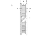
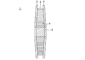
本発明が適用されたリール部材1は、図1に示すように、テープ状の接着フィルム2が巻回される巻芯3と、巻芯3の両側に設けられたリールフランジ5とを備える。リール部材1に巻回された接着フィルム2は、巻芯3に巻回されたフィルム巻装体4を形成する。
As shown in FIG. 1, a
[巻芯/リールフランジ]
巻芯3は、円筒形状をなし、後述する接着フィルム2と略同じ幅を有する。また、巻芯3は、中心部にリール部材1を回転駆動する図示しない回転装置が挿通する挿通口3aが形成されている。そして、巻芯3は、両側は一対のリールフランジ5が係合され、リールフランジ5と一体に回転される。
[Core / reel flange]
The winding
一対のリールフランジ5は、巻芯3に巻回された接着フィルム2を挟持するものであり、例えば透明なプラスチック材料を用いて円盤状に形成されている。また、リールフランジ5は、接着フィルム2と接する面に、静電処理を施すようにしてもよい。静電処理を施す方法としては、例えば、ポリチオフェン等の化合物を塗布する方法が挙げられる。
The pair of
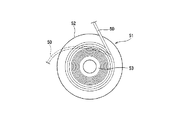
[フィルム巻装体を挟持]
リール部材1は、巻芯3にテープ状の接着フィルム2が巻回されるとともに、図2に示すように、一対のリールフランジ5によって接着フィルム2の巻装体4を挟持する。これにより、リール部材1は、フィルム巻装体4に巻締まりが生じて巻芯3付近に巻圧が累積することを防止することができる。
[Hold film roll]
In the
すなわち、リール部材1のフィルム巻装体4は、リールフランジ5に挟持されることで、巻圧の内周側への伝達を抑制し、巻締まりの発生及び内周側への巻圧の累積を防止することができる。したがって、リール部材1は、接着フィルム2のバインダー樹脂のはみ出しや、はみ出したバインダー樹脂がリールフランジ5に付着して正常に接着フィルム2が巻き出せなくなるブロッキングを防止することができる。
That is, the film winding body 4 of the
また、リール部材1は、一対のリールフランジ5によってフィルム巻装体4を挟持することにより、巻芯3やリールフランジ5の回転が規制された状態で接着フィルム2が強引に引っ張られた場合にも、接着フィルム2の引き出しを抑制し、巻締まりの発生及び巻圧の累積を防止することができる。したがって、リール部材1によれば、例えば接着フィルム2を搬送装置のローラに引き回す際に、リール部材1の回転がロックされた状態で接着フィルム2が引っ張られた場合にも、接着フィルム2を容易に引き出すことができず、巻締まりによるバインダー樹脂のはみ出しやブロッキングの発生を防止することができる。
Further, the
リール部材1は、図2に示すように、一対のリールフランジ5の間隔を接着フィルム2の幅と同距離にすることで、リールフランジ5によって接着フィルム2を挟持することができる。
As shown in FIG. 2, the
[リブ]
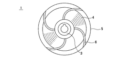
また、リール部材1は、図3に示すように、フィルム巻装体4と対峙する内面に、内周側から外周側に向かって複数のリブ6を放射状に形成し、当該リブ6によってフィルム巻装体4を挟持してもよい。このとき、リール部材1は、一対のリールフランジ5に相対向して設けられたリブ6の間隔を、接着フィルム2の幅と同距離にすることで、リールフランジ5のリブ6によって接着フィルム2のフィルム巻装体4を挟持することができる。
[rib]
In addition, as shown in FIG. 3, the
リール部材1は、リブ6によってフィルム巻装体4を挟持することで、リールフランジ5の全面でフィルム巻装体4を挟持する場合に比してフィルム巻装体4との接触面積を低減させ、これにより接着フィルム2よりはみ出したバインダー樹脂との接触によるブロッキングの発生を抑制することができる。
The
なお、リブ6は、図4に示すように、断面略半円状に形成してもよく、また、図5に示すように、断面が略矩形状に形成されてもよい。また、リブ6は、例えば、幅0.5mm〜5.0mm、高さ0.03mm〜2.0mmのサイズで形成することができる。
The
また、リブ6は、図6に示すように、リールフランジ5の内周側から外周側にかけて湾曲する形状であってもよい。この場合、リール部材1は、フィルム巻装体4とリブ6との接触面積が大きいため、リブ6の本数を減らすことができる。
Further, as shown in FIG. 6, the
また、リブ6は、図7に示すように、一対のリールフランジ5の間で所定間隔毎に交互に設けるようにしてもよい。この場合、リール部材1は、リブ6とフィルム巻装体4とが交互に接触するため、フィルム巻装体4への負荷が少なく、接着フィルム2の形状安定性に優れる。
Further, as shown in FIG. 7, the
さらに、リブ6は、図8に示すように、幅広の矩形板状に形成してもよい。この場合、幅広のリブ6に当接されることで、フィルム巻装体4はリブ6によって広汎に支持されるため、リブ6の本数を減らすとともに、リブ6とフィルム巻装体4との接触面積は維持することができる。
Furthermore, the
なお、リール部材1は、リブ6をリールフランジ5の内周から外周縁にかけて形成することで、フィルム巻装体4に累積した巻圧や、リールフランジ5そのものに生じる内部応力が径時変化によって発現することにより、リールフランジ5に歪みが生じることを抑制することができる。したがって、一対のリールフランジ5の間隔が開くことによる接着フィルム2の脱落を防止することができる。
In the
近年は、電子部品の微細化や接着領域の狭小化に伴い、接着フィルム2の幅も細くなってきているため、一対のリールフランジ5の間隔誤差も許容度が低くなっている。また、接着フィルム2の長尺化に伴い、リールフランジ5の径も大きくなり、全面に亘って寸法公差を維持することが厳しくなっている。そこで、リールフランジ5は、寸法公差の少ないリブ6を内周から外周縁にかけて形成することで、リールフランジ5の寸法公差を吸収し、リールフランジ5の歪みによる一対のリールフランジの離間や、これによる接着フィルム2のフィルム巻装体4からの脱落(図20参照)を防止し、接着フィルム2の長尺化、細幅化を図ることができる。
In recent years, since the width of the
また、リール部材1は、巻芯3に対して一対のリールフランジ5が互いに近接離間可能に係合することにより、接着フィルム2の幅に応じてリールフランジ5間の距離や、リブ6間の距離を調整することができる。かかる構成は、例えば、巻芯3に設けた挿通口3a等の係合口に挿通する係合軸をリールフランジ5の内周面に立設し、当該係合軸の挿通深さによってリールフランジ5間の距離を調整する構成が例示できる。
In addition, the
[巻芯2重コア]
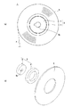
また、図9(a)に示すように、リール部材1は、巻芯3を、小径コア8と、小径コア8に嵌合されるとともに接着フィルム2が巻回される大径コア9とから構成してもよい。小径コア8には、中心部にリール部材1を回転駆動する図示しない回転装置が挿通する挿通口8aが形成されている。大径コア9は、小径コア8から着脱可能に嵌合されている。
[Core double core]
Further, as shown in FIG. 9A, the
このような巻芯3は、小径コア8と大径コア9とが嵌合されることで拡径された状態で、大径コア9に接着フィルム2が巻回される。そして、巻芯3は、接着フィルム2の巻回が終了すると、図9(b)に示すように、大径コア9が小径コア8から取り外されることにより縮径される。これにより、図10に示すように、リール部材1は、フィルム巻装体4と小径コア8との間に空隙10が設けられる。この空隙10は、フィルム巻装体4に巻締まりが発生した際に、巻装体の内周側に累積する巻圧を吸収するための領域である。空隙10が設けられることにより、リール部材1は、巻圧が内周側に伝達されると、巻装体内周側の接着フィルム2によって巻圧が解放されることで、巻圧の累積を抑制し、接着フィルム2のはみ出しやブロッキングを防止することができる。
In such a
[エアシャフト]
また、リール部材1は、巻芯3を大小のコア8,9から構成する他にも、図11に示すように、巻芯3を、外径が可変とされたエアシャフト11で構成してもよい。この場合、巻芯3は、図11(a)に示すように、ラグ12を突出させて拡径された状態で接着フィルム2が巻回される。そして、巻芯3は、接着フィルム2の巻回が終了すると、図11(b)に示すように、ラグ12がシャフト内部に後退し縮径する。これによっても、図10に示すように、リール部材1は、フィルム巻装体4とエアシャフト11との間に空隙10が設けられる。
[Air shaft]
The
ここで、上述したように、リール部材1は、一対のリールフランジ5でフィルム巻装体4を挟持しているため、接着フィルム2の巻回が終了した後に、大径コア9を取り外し、あるいはラグ12を後退させることにより巻芯3を縮径させても、フィルム巻装体4がばらけることなく巻回状態を維持することができる。
Here, as described above, since the
また、図12に示すように、リールフランジ5にリブ6が形成されていないリール部材1においても、巻芯3を縮径させて空隙10を設けてもよい。
As shown in FIG. 12, also in the
[フィルム巻装体の内周側から外周側にかけて強く挟持]
また、リール部材1は、一対のリールフランジによって、フィルム巻装体4の内周側から外周側にかけて強く挟持していくようにしてもよい。これにより、リール部材1は、フィルム巻装体4の外周側から巻圧が内周側へ累積していくことを防止し、はみ出しやブロッキングが生じやすいフィルム巻装体4の内周側の巻締まりを抑制することができる。
[Holding strongly from the inner circumference side to the outer circumference side of the film winding body]
Further, the
また、リール部材1は、リール部材1の回転がロックされ巻芯3やリールフランジ5の回転が規制された状態で接着フィルム2が強引に引っ張られた場合にも、接着フィルム2を容易に引き出すことができず、巻締まりによるバインダー樹脂のはみ出しやブロッキングの発生を防止することができる。
Further, the
さらに、リール部材1は、接着フィルム2の長尺化に伴いリールフランジ5が大径化することで、フィルム巻装体4の内周側と外周側とで均一な圧力で挟持することが困難となるが、フィルム巻装体4の内周側から外周側にかけて強く挟持するように構成することで、外周側における挟持圧力の不足を解消することができる。
Furthermore, the
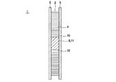
一対のリールフランジによって、フィルム巻装体4の内周側から外周側にかけて強く挟持していく構成としては、例えば図13に示すように、リールフランジ5に、内周側から外周側にかけて高さが増大するテーパ状のリブ14を設けることにより形成することができる。なお、図13では、巻芯3を縮径することによりフィルム巻装体4との間に空隙10を設けている。また、テーパ状リブ14の角度θ1は、例えば0.1°〜5°の範囲で設定され、好ましくは0.3°に設定される。
For example, as shown in FIG. 13, the
また、リール部材1は、図14に示すように、リールフランジ5の外周側を屈曲あるいは湾曲させることで、一対のリールフランジ5の外周側の間隔を狭めるようにしてもよい。このとき、リールフランジ5は、リブ6を形成し、リブ6によってフィルム巻装体4の外周側を強く挟持してもよく、図15に示すように、リブ6を設けず、リールフランジ5の外周側内面によってフィルム巻装体4の外周側を強く挟持してもよい。また、リールフランジ5の傾斜角度θ2は、例えば0.2°〜5°の範囲で設定される。
Further, as shown in FIG. 14, the
[接着フィルムの巻回方法]
次いで、リール部材1へ接着フィルム2を巻回する工程について説明する。リール部材1は、一対のリールフランジ5によってフィルム巻装体4を挟持するため、一対のリールフランジ5の間隔がほぼ接着フィルム2の幅と同じとされている。そのため、リール部材1は、接着フィルム2を巻芯3に巻回させる際には、図16に示すように、接着フィルム2を巻芯3の外周に対して傾けるようにガイドしながら一対のリールフランジ5間を通す。
[Method of winding adhesive film]
Next, the process of winding the
すなわち、リール部材1に対して、従来通り巻芯3の外周面と平行に接着フィルム2を通したのでは、接着フィルム2の両側が一対のリールフランジ5の内周面と摺接して、巻芯3への巻回が阻害されてしまう。そこで、リール部材1へ接着フィルム2を巻回する際には、接着フィルム2をガイドローラ15によって、一対のリールフランジ5と摺接しない角度まで巻芯3の外周面に対して傾ける。ガイドローラ15の傾斜角度θ3は、例えば0.1°〜15°の範囲で設定される。
That is, when the
一対のリールフランジ5間を通った接着フィルム2は、巻芯3の外周面と平行に巻回されてフィルム巻装体4を形成し、一対のリールフランジ5の内周面、あるいはリブ6,14に挟持されていく。これにより、接着フィルム2をリール部材1に対してスムーズに巻回することができる。
The
[接着フィルムの巻き出し方法]
同様に、リール部材1から接着フィルム2を巻き出す工程においても、接着フィルム2をガイドローラ15によって巻芯3の外周に対して傾けるようにガイドしながら一対のリールフランジ5間を通す。これにより、接着フィルム2は、リールフランジ5に摺接することなく、リール部材1からスムーズに巻き出されることができる。
[How to unwind adhesive film]
Similarly, in the step of unwinding the
このとき、巻き出されていない接着フィルム2は、フィルム巻装体4を形成し、一対のリールフランジ5の内周面、あるいはリブ6,14に挟持されているため、巻き出しの際に掛かる負荷がフィルム巻装体4に巻圧として伝達することが防止され、巻締まりによるバインダー樹脂のはみ出しやブロッキングを防止することができる。
At this time, the unwound
[接着フィルムの構成]
ここで、リール部材1に巻回される接着フィルム2について説明する。接着フィルム2は、図17に示すように、接着剤層20と接着剤層20を支持する支持体となるベースフィルム21とを備える。
[Composition of adhesive film]
Here, the
接着剤層20は、バインダー(絶縁性接着剤組成物)20aに導電性粒子22を含有する異方性導電フィルム(ACF:Anisotropic Conductive Film)とすることができるが、これに限定されず、バインダー20aに導電性粒子22を含有しない絶縁性接着フィルム(NCF:Non-Conductive Film)であってもよい。
The
接着フィルム2のバインダー20aは、例えば、膜形成樹脂、熱硬化性樹脂、潜在性硬化剤、シランカップリング剤等を含有する通常のバインダーを用いることができる。接着フィルム2は、バインダー20aに導電性粒子22が分散された異方性導電組成物、又は、バインダー20aに導電性粒子22を含有しない絶縁性接着剤組成物を、ベースフィルム21上に塗布することにより、ベースフィルム21上に形成される。
As the
ベースフィルム21は、バインダー20aをフィルム状に支持するものであり、例えば、PET(Poly Ethylene Terephthalate)、OPP(Oriented Polypropylene)、PMP(Poly-4-methlpentene−1)、PTFE(Polytetrafluoroethylene)等にシリコーン等の剥離剤を塗布することにより形成される。
The
バインダー20aに含有される膜形成樹脂としては、平均分子量が10000〜80000程度の樹脂が好ましい。膜形成樹脂としては、エポキシ樹脂、変形エポキシ樹脂、ウレタン樹脂、フェノキシ樹脂等の各種の樹脂が挙げられる。中でも、膜形成状態、接続信頼性等の観点からフェノキシ樹脂が特に好ましい。
The film forming resin contained in the
熱硬化性樹脂としては、常温で流動性を有していれば特に限定されず、例えば、市販のエポキシ樹脂、アクリル樹脂等が挙げられる。 The thermosetting resin is not particularly limited as long as it has fluidity at room temperature, and examples thereof include commercially available epoxy resins and acrylic resins.
エポキシ樹脂としては、特に限定されないが、例えば、ナフタレン型エポキシ樹脂、ビフェニル型エポキシ樹脂、フェノールノボラック型エポキシ樹脂、ビスフェノール型エポキシ樹脂、スチルベン型エポキシ樹脂、トリフェノールメタン型エポキシ樹脂、フェノールアラルキル型エポキシ樹脂、ナフトール型エポキシ樹脂、ジシクロペンタジエン型エポキシ樹脂、トリフェニルメタン型エポキシ樹脂等が挙げられる。これらは単独でも、2種以上の組み合わせであってもよい。 The epoxy resin is not particularly limited. For example, naphthalene type epoxy resin, biphenyl type epoxy resin, phenol novolac type epoxy resin, bisphenol type epoxy resin, stilbene type epoxy resin, triphenolmethane type epoxy resin, phenol aralkyl type epoxy resin. Naphthol type epoxy resin, dicyclopentadiene type epoxy resin, triphenylmethane type epoxy resin and the like. These may be used alone or in combination of two or more.
アクリル樹脂としては、特に制限はなく、目的に応じてアクリル化合物、液状アクリレート等を適宜選択することができる。例えば、メチルアクリレート、エチルアクリレート、イソプロピルアクリレート、イソブチルアクリレート、エポキシアクリレート、エチレングリコールジアクリレート、ジエチレングリコールジアクリレート、トリメチロールプロパントリアクリレート、ジメチロールトリシクロデカンジアクリレート、テトラメチレングリコールテトラアクリレート、2−ヒドロキシ−1,3−ジアクリロキシプロパン、2,2−ビス[4−(アクリロキシメトキシ)フェニル]プロパン、2,2−ビス[4−(アクリロキシエトキシ)フェニル]プロパン、ジシクロペンテニルアクリレート、トリシクロデカニルアクリレート、トリス(アクリロキシエチル)イソシアヌレート、ウレタンアクリレート、エポキシアクリレート等を挙げることができる。なお、アクリレートをメタクリレートにしたものを用いることもできる。これらは、1種単独で使用してもよいし、2種以上を併用してもよい。 There is no restriction | limiting in particular as an acrylic resin, According to the objective, an acrylic compound, liquid acrylate, etc. can be selected suitably. For example, methyl acrylate, ethyl acrylate, isopropyl acrylate, isobutyl acrylate, epoxy acrylate, ethylene glycol diacrylate, diethylene glycol diacrylate, trimethylolpropane triacrylate, dimethylol tricyclodecane diacrylate, tetramethylene glycol tetraacrylate, 2-hydroxy- 1,3-diacryloxypropane, 2,2-bis [4- (acryloxymethoxy) phenyl] propane, 2,2-bis [4- (acryloxyethoxy) phenyl] propane, dicyclopentenyl acrylate, tricyclo Examples include decanyl acrylate, tris (acryloxyethyl) isocyanurate, urethane acrylate, and epoxy acrylate. In addition, what made acrylate the methacrylate can also be used. These may be used individually by 1 type and may use 2 or more types together.
潜在性硬化剤としては、特に限定されないが、例えば、加熱硬化型、UV硬化型等の各種硬化剤が挙げられる。潜在性硬化剤は、通常では反応せず、熱、光、加圧等の用途に応じて選択される各種のトリガにより活性化し、反応を開始する。熱活性型潜在性硬化剤の活性化方法には、加熱による解離反応などで活性種(カチオンやアニオン)を生成する方法、室温付近ではエポキシ樹脂中に安定に分散しており高温でエポキシ樹脂と相溶・溶解し、硬化反応を開始する方法、モレキュラーシーブ封入タイプの硬化剤を高温で溶出して硬化反応を開始する方法、マイクロカプセルによる溶出・硬化方法等が存在する。熱活性型潜在性硬化剤としては、イミダゾール系、ヒドラジド系、三フッ化ホウ素−アミン錯体、スルホニウム塩、アミンイミド、ポリアミン塩、ジシアンジアミド等や、これらの変性物があり、これらは単独でも、2種以上の混合体であってもよい。中でも、マイクロカプセル型イミダゾール系潜在性硬化剤が好適である。 The latent curing agent is not particularly limited, and examples thereof include various curing agents such as a heat curing type and a UV curing type. The latent curing agent does not normally react, but is activated by various triggers selected according to applications such as heat, light, and pressure, and starts the reaction. The activation method of the thermally activated latent curing agent includes a method of generating active species (cations and anions) by a dissociation reaction by heating, and the like. There are a method of dissolving and dissolving and starting a curing reaction, a method of starting a curing reaction by eluting a molecular sieve encapsulated type curing agent at a high temperature, an elution and curing method using microcapsules, and the like. Thermally active latent curing agents include imidazole, hydrazide, boron trifluoride-amine complexes, sulfonium salts, amine imides, polyamine salts, dicyandiamide, etc., and modified products thereof. The above mixture may be sufficient. Among these, a microcapsule type imidazole-based latent curing agent is preferable.
シランカップリング剤としては、特に限定されないが、例えば、エポキシ系、アミノ系、メルカプト・スルフィド系、ウレイド系等を挙げることができる。シランカップリング剤を添加することにより、有機材料と無機材料との界面における接着性が向上される。 Although it does not specifically limit as a silane coupling agent, For example, an epoxy type, an amino type, a mercapto sulfide type, a ureido type etc. can be mentioned. By adding the silane coupling agent, the adhesion at the interface between the organic material and the inorganic material is improved.
導電性粒子22としては、異方性導電フィルムにおいて使用されている公知の何れの導電性粒子を挙げることができる。導電性粒子22としては、例えば、ニッケル、鉄、銅、アルミニウム、錫、鉛、クロム、コバルト、銀、金等の各種金属や金属合金の粒子、金属酸化物、カーボン、グラファイト、ガラス、セラミック、プラスチック等の粒子の表面に金属をコートしたもの、或いは、これらの粒子の表面に更に絶縁薄膜をコートしたもの等が挙げられる。樹脂粒子の表面に金属をコートしたものである場合、樹脂粒子としては、例えば、エポキシ樹脂、フェノール樹脂、アクリル樹脂、アクリロニトリル・スチレン(AS)樹脂、ベンゾグアナミン樹脂、ジビニルベンゼン系樹脂、スチレン系樹脂等の粒子を挙げることができる。
Examples of the
なお、上述した説明では、ベースフィルム21上にACF又はNCFからなる接着フィルム2が積層されてなる接着フィルム2を用いたが、この例に限定されるものではない。例えば、フィルム積層体は、ACFとNCFとが積層された2層以上の異方性導電フィルムとしてもよい。
In the above description, the
また、接着フィルム2は、接着フィルム2のベースフィルム21が積層された面とは反対の面側にもカバーフィルムを設ける構成としてもよい。また、例えば、複数の太陽電池セルの電極同士を電気的に接続するための銅箔付き接着フィルムとしてもよい。
Moreover, the
次いで、本発明の実施例について説明する。本実施例では、一対のリールフランジによって接着フィルムの巻装体を挟持しているリール部材と、従来のリール部材とを用意し、接着フィルムを引き出し、接着フィルムの長さ毎にはみ出しやブロッキングの発生について観察した。 Next, examples of the present invention will be described. In this embodiment, a reel member that sandwiches the wound body of the adhesive film with a pair of reel flanges and a conventional reel member are prepared, the adhesive film is pulled out, and the length of the adhesive film is extended or blocked. The occurrence was observed.
実施例1では、フィルム巻装体と対峙する内面に、内周側から外周側に向かって複数の直線状のリブを放射状に12本形成し、当該リブによってフィルム巻装体を挟持したリール部材を用いた(図3参照)。リールフランジの外径は250mmである。 In Example 1, a reel member in which 12 linear ribs are radially formed on the inner surface facing the film winding body from the inner peripheral side to the outer peripheral side, and the film winding body is sandwiched by the ribs. Was used (see FIG. 3). The outer diameter of the reel flange is 250 mm.
実施例2では、大径コアと小径コアとからなる巻芯を用い、フィルム巻装体と巻芯との間に空隙が形成されたリール部材を用いた他は、実施例1と同一の条件とした(図10参照)。 In Example 2, the same conditions as in Example 1 were used except that a winding core composed of a large-diameter core and a small-diameter core was used and a reel member in which a gap was formed between the film winding body and the winding core was used. (See FIG. 10).
実施例3では、フィルム巻装体と対峙する内面に、内周側から外周側に向かって複数のテーパ状のリブを放射状に12本形成し、当該テーパ状リブによってフィルム巻装体を挟持したリール部材を用いた(図13参照)。リールフランジの外径は300mmである。テーパ状リブのテーパ角度は、0.3°である。また、実施例3では、大径コアと小径コアとからなる巻芯を用い、フィルム巻装体と巻芯との間に空隙を設けた。 In Example 3, 12 taper-shaped ribs were radially formed on the inner surface facing the film winding body from the inner peripheral side toward the outer peripheral side, and the film winding body was sandwiched by the tapered ribs. A reel member was used (see FIG. 13). The outer diameter of the reel flange is 300 mm. The taper angle of the tapered rib is 0.3 °. Moreover, in Example 3, the core which consists of a large diameter core and a small diameter core was used, and the space | gap was provided between the film winding body and the core.
比較例1では、フィルム巻装体とリールフランジとの間にクリアランスを有する従来のリール部材を用いた(図18参照)。 In Comparative Example 1, a conventional reel member having a clearance between the film winding body and the reel flange was used (see FIG. 18).
実施例及び比較例に係るリール部材には、それぞれ、接着フィルムを300m、500m、600m、700m巻回し、はみ出し及びブロッキングの有無を観察した。はみ出し及びブロッキングが認められない場合を○、はみ出しは認められるがブロッキングは認められない場合は、実用上問題なしとして△とし、はみ出し及びブロッキングが認められた場合は、実用に耐えられないものとして×とした。結果を表1に示す。 Each of the reel members according to Examples and Comparative Examples was wound with an adhesive film of 300 m, 500 m, 600 m, and 700 m, and observed the presence or absence of protrusion and blocking. ○ when no protrusion or blocking is observed, and when protrusion is recognized but blocking is not recognized, it is △ as no problem in practical use, and when protrusion and blocking are recognized, it is assumed that it cannot be put into practical use. It was. The results are shown in Table 1.

表1に示すように、実施例1〜3によれば、700m巻回した状態でも、ブロッキングは認められず、実用に耐えられるものであった。一方、比較例1では、300mまでは問題ないが、500m以上巻回したものでははみ出し及びブロッキングが認められ、実用に耐えられなかった。これより、一対のリールフランジによって接着フィルムの巻装体を挟持することにより、長尺化を図ることができることがわかる。 As shown in Table 1, according to Examples 1 to 3, blocking was not recognized even in a state where the film was wound for 700 m, and it was able to withstand practical use. On the other hand, in Comparative Example 1, there was no problem up to 300 m, but protrusion and blocking were observed in those wound up to 500 m or more, and they could not be put into practical use. From this, it can be seen that the length can be increased by sandwiching the wound body of the adhesive film between the pair of reel flanges.
また、実施例1〜3をみると、実施例1よりも空隙を設けた実施例2の方が長尺化に際してはみ出しが抑制された。これより、空隙を形成することが巻圧の累積抑制に有利であることがわかる。また、実施例2よりもテーパ状リブが形成された実施例3の方が長尺化に際してはみ出しが抑制された。これより、フィルム巻装体の内周側から外周側にかけて強く挟持していくことが巻圧の累積抑制に有利であることがわかる。 Moreover, when Examples 1-3 were seen, the protrusion of Example 2 which provided the space | gap rather than Example 1 was suppressed when lengthening. From this, it can be seen that the formation of voids is advantageous for suppressing the cumulative winding pressure. Further, the protrusion of Example 3 in which the tapered rib was formed was suppressed from being extended when the length was increased. From this, it can be seen that it is advantageous for the accumulation suppression of the winding pressure that the film winding body is strongly held from the inner peripheral side to the outer peripheral side.
1 リール部材、2 接着フィルム、3 巻芯、3a 挿通口、4 フィルム巻装体、5 リールフランジ、6 リブ、8 小径コア、9 大径コア、10 空隙、11 エアシャフト、12 ラグ、14 テーパ状リブ、20 接着剤層、21 ベースフィルム、22 導電性粒子 1 reel member, 2 adhesive film, 3 roll core, 3a insertion port, 4 film winding body, 5 reel flange, 6 rib, 8 small diameter core, 9 large diameter core, 10 air gap, 11 air shaft, 12 lug, 14 taper Rib, 20 adhesive layer, 21 base film, 22 conductive particles
Claims (10)
上記巻芯の両側に設けられた一対のリールフランジとを備え、
上記一対のリールフランジは、上記接着フィルムの巻装体の内周側から外周側にかけて強く挟持していくリール部材。 A core around which a tape-like adhesive film is wound;
A pair of reel flanges provided on both sides of the core,
The pair of reel flanges are reel members that are strongly clamped from the inner peripheral side to the outer peripheral side of the wound body of the adhesive film .
上記巻芯の両側に設けられた一対のリールフランジとを備え、A pair of reel flanges provided on both sides of the core,
上記一対のリールフランジによって上記接着フィルムの巻装体を挟持し、Holding the wound body of the adhesive film by the pair of reel flanges,
上記巻芯は、小径コアと、上記小径コアに嵌合されるとともに上記接着フィルムが巻回される大径コアとを有し、The winding core has a small-diameter core and a large-diameter core that is fitted to the small-diameter core and on which the adhesive film is wound,
上記大径コアは、上記接着フィルムが巻回された後、上記小径コアから取り外されるリール部材。The large-diameter core is a reel member that is removed from the small-diameter core after the adhesive film is wound.
上記接着フィルムを上記巻芯の外周面に対して傾けるようにガイドしながら上記一対のリールフランジ間を通す接着フィルムの巻回方法。 A winding core on which a tape-shaped adhesive film is wound, and a pair of reel flanges provided on both sides of the winding core, the pair of reel flanges from the inner peripheral side of the wound body of the adhesive film In the method of winding the adhesive film around the reel member that is strongly clamped toward the outer peripheral side ,
A method for winding an adhesive film in which the adhesive film is passed through the pair of reel flanges while being guided so as to be inclined with respect to the outer peripheral surface of the core.
上記接着フィルムを上記巻芯の外周面に対して傾けるようにガイドしながら上記一対のリールフランジ間を通す接着フィルムの巻き出し方法。 A winding core on which a tape-like adhesive film is wound, and a pair of reel flanges provided on both sides of the winding core, the pair of reel flanges from the inner peripheral side of the wound body of the adhesive film In the unwinding method of unwinding the adhesive film from the reel member that is strongly clamped toward the outer peripheral side ,
A method for unwinding the adhesive film in which the adhesive film is passed through the pair of reel flanges while being guided to be inclined with respect to the outer peripheral surface of the core.
Priority Applications (6)
| Application Number | Priority Date | Filing Date | Title |
|---|---|---|---|
| JP2012087758A JP5982159B2 (en) | 2012-04-06 | 2012-04-06 | Reel member, adhesive film winding method, adhesive film unwinding method |
| KR1020147030861A KR102123310B1 (en) | 2012-04-06 | 2013-04-01 | Reel member, winding method for adhesive film, and unwinding method for adhesive film |
| PCT/JP2013/059949 WO2013151013A1 (en) | 2012-04-06 | 2013-04-01 | Reel member, winding method for adhesive film, and unwinding method for adhesive film |
| KR1020207014474A KR102268491B1 (en) | 2012-04-06 | 2013-04-01 | Reel member, winding method for adhesive film, and unwinding method for adhesive film |
| CN201380017718.5A CN104203789B (en) | 2012-04-06 | 2013-04-01 | Reel parts, the method for winding of adhesive film, adhesive film roll out method |
| TW102112452A TW201400394A (en) | 2012-04-06 | 2013-04-08 | Reel member, winding method for adhesive film, and unwinding method for adhesive film |
Applications Claiming Priority (1)
| Application Number | Priority Date | Filing Date | Title |
|---|---|---|---|
| JP2012087758A JP5982159B2 (en) | 2012-04-06 | 2012-04-06 | Reel member, adhesive film winding method, adhesive film unwinding method |
Publications (2)
| Publication Number | Publication Date |
|---|---|
| JP2013216436A JP2013216436A (en) | 2013-10-24 |
| JP5982159B2 true JP5982159B2 (en) | 2016-08-31 |
Family
ID=49300496
Family Applications (1)
| Application Number | Title | Priority Date | Filing Date |
|---|---|---|---|
| JP2012087758A Active JP5982159B2 (en) | 2012-04-06 | 2012-04-06 | Reel member, adhesive film winding method, adhesive film unwinding method |
Country Status (5)
| Country | Link |
|---|---|
| JP (1) | JP5982159B2 (en) |
| KR (2) | KR102123310B1 (en) |
| CN (1) | CN104203789B (en) |
| TW (1) | TW201400394A (en) |
| WO (1) | WO2013151013A1 (en) |
Families Citing this family (4)
| Publication number | Priority date | Publication date | Assignee | Title |
|---|---|---|---|---|
| US11420843B2 (en) | 2015-08-10 | 2022-08-23 | Dexerials Corporation | Reel member, film housing body, and method for manufacturing reel member |
| KR102108476B1 (en) * | 2017-10-31 | 2020-05-07 | 김태민 | crystal chip reel for printing system using crystal chip |
| JP2021080098A (en) | 2019-11-22 | 2021-05-27 | デクセリアルズ株式会社 | Reel member, adhesive film wound body |
| EP4207965A1 (en) * | 2021-12-31 | 2023-07-05 | Nexperia B.V. | An electronic component packing reel |
Family Cites Families (17)
| Publication number | Priority date | Publication date | Assignee | Title |
|---|---|---|---|---|
| JPS593418Y2 (en) * | 1978-09-30 | 1984-01-30 | ソニー株式会社 | tape reel |
| JP2523990Y2 (en) * | 1989-09-29 | 1997-01-29 | 金井 宏之 | Metal wire wrapping reel |
| SE502768C2 (en) * | 1994-03-29 | 1996-01-08 | Ulvator Ab | Metal-free disposable drum for an elongated flexible object |
| CN1152383C (en) * | 1996-05-30 | 2004-06-02 | 可隆株式会社 | Reel for winding photosensitive film |
| JPH10329992A (en) * | 1997-05-29 | 1998-12-15 | Nec Toyama Ltd | Carrier tape reel |
| KR200221348Y1 (en) * | 1997-06-11 | 2001-05-02 | 윤종용 | Optical fiber spool and spool cover |
| JP3680669B2 (en) | 1999-12-17 | 2005-08-10 | ソニーケミカル株式会社 | Multilayer anisotropic conductive film laminate |
| US7237746B2 (en) * | 2003-12-08 | 2007-07-03 | Sonoco Development, Inc. | Spool having reversing spiral guide |
| WO2007015372A1 (en) | 2005-08-04 | 2007-02-08 | Hitachi Chemical Co., Ltd. | Anisotropic conductive film and method for producing same |
| EP2364944A3 (en) * | 2006-06-21 | 2011-12-21 | Hitachi Chemical Company, Ltd. | Tape roll |
| CN101528878A (en) * | 2006-10-31 | 2009-09-09 | 日立化成工业株式会社 | Adhesive tape and adhesive tape roll |
| KR100961589B1 (en) * | 2007-05-23 | 2010-06-04 | 히다치 가세고교 가부시끼가이샤 | Adhesive rill and circuit connector manufacturing method using the same |
| JP5038096B2 (en) * | 2007-11-01 | 2012-10-03 | 花王株式会社 | Method for unwinding roll-shaped roll and core |
| JP5471115B2 (en) * | 2009-07-24 | 2014-04-16 | 日立化成株式会社 | reel |
| JP2011126711A (en) * | 2009-11-18 | 2011-06-30 | Hitachi Chem Co Ltd | Reel for anisotropic conductive film, anisotropic conductive film winding and connecting method of circuit member |
| CN103003178B (en) * | 2010-03-23 | 2015-09-30 | 日立化成株式会社 | Adhesive tape reel |
| JP5759168B2 (en) * | 2010-12-24 | 2015-08-05 | デクセリアルズ株式会社 | Reel body and method for manufacturing reel body |
-
2012
- 2012-04-06 JP JP2012087758A patent/JP5982159B2/en active Active
-
2013
- 2013-04-01 WO PCT/JP2013/059949 patent/WO2013151013A1/en active Application Filing
- 2013-04-01 KR KR1020147030861A patent/KR102123310B1/en active IP Right Grant
- 2013-04-01 CN CN201380017718.5A patent/CN104203789B/en active Active
- 2013-04-01 KR KR1020207014474A patent/KR102268491B1/en active IP Right Grant
- 2013-04-08 TW TW102112452A patent/TW201400394A/en unknown
Also Published As
| Publication number | Publication date |
|---|---|
| WO2013151013A1 (en) | 2013-10-10 |
| CN104203789B (en) | 2016-10-05 |
| TW201400394A (en) | 2014-01-01 |
| CN104203789A (en) | 2014-12-10 |
| TWI562949B (en) | 2016-12-21 |
| KR20200060526A (en) | 2020-05-29 |
| JP2013216436A (en) | 2013-10-24 |
| KR20140143220A (en) | 2014-12-15 |
| KR102123310B1 (en) | 2020-06-16 |
| KR102268491B1 (en) | 2021-06-24 |
Similar Documents
| Publication | Publication Date | Title |
|---|---|---|
| JP2017168465A (en) | Method for manufacturing anisotropically conductive film, connected structure, and method of manufacturing connected structure | |
| KR101909300B1 (en) | Reel body and process for production of reel body | |
| JP5982159B2 (en) | Reel member, adhesive film winding method, adhesive film unwinding method | |
| JP2013216833A (en) | Device for applying adhesive film, method for applying adhesive film, and connection structure | |
| JP2015187221A (en) | Adhesive film, film wound body, and method for manufacturing connected body | |
| KR102213418B1 (en) | Recommended adhesive film, manufacturing method of recommended adhesive film | |
| JP5981173B2 (en) | Manufacturing method of connection body, bonding method of adhesive film, drawing method of adhesive film, and adhesive film | |
| JP5982158B2 (en) | Reel member | |
| KR101808347B1 (en) | Film laminate, sticking method of film laminate, connection method using film laminate and connection structure | |
| JP2011126711A (en) | Reel for anisotropic conductive film, anisotropic conductive film winding and connecting method of circuit member | |
| JP6431256B2 (en) | Adhesive film, film winding body, connection structure manufacturing method, connection method, connection structure | |
| TWI494956B (en) | An anisotropic conductive film, an anisotropic conductive film manufacturing method, a connection method between electronic members, and a connection structure | |
| JP5897942B2 (en) | Reel member, film winding method, film unwinding method | |
| JP5912700B2 (en) | Reel member, adhesive film winding method and unwinding method | |
| JP6000612B2 (en) | Connection structure manufacturing method, connection method, and connection structure | |
| JP6524283B2 (en) | Adhesive film, film wound body, method of manufacturing connected body | |
| JP5899035B2 (en) | Reel member, reel body, film laminate winding method and drawing method | |
| JP6366975B2 (en) | Adhesive film winding body, connection body manufacturing method, and electronic component connection method | |
| WO2013146479A1 (en) | Method for manufacturing connector, method for connecting electronic component, connecting member, and method for manufacturing connecting member | |
| JP2013201351A (en) | Manufacturing method of connection body, connection method of connection member, and connection body | |
| JP2015024900A (en) | Reel member, method of drawing adhesive film and connection method |
Legal Events
| Date | Code | Title | Description |
|---|---|---|---|
| A621 | Written request for application examination |
Free format text: JAPANESE INTERMEDIATE CODE: A621 Effective date: 20150403 |
|
| A131 | Notification of reasons for refusal |
Free format text: JAPANESE INTERMEDIATE CODE: A131 Effective date: 20160105 |
|
| A02 | Decision of refusal |
Free format text: JAPANESE INTERMEDIATE CODE: A02 Effective date: 20160426 |
|
| A521 | Request for written amendment filed |
Free format text: JAPANESE INTERMEDIATE CODE: A523 Effective date: 20160610 |
|
| A911 | Transfer to examiner for re-examination before appeal (zenchi) |
Free format text: JAPANESE INTERMEDIATE CODE: A911 Effective date: 20160627 |
|
| TRDD | Decision of grant or rejection written | ||
| A01 | Written decision to grant a patent or to grant a registration (utility model) |
Free format text: JAPANESE INTERMEDIATE CODE: A01 Effective date: 20160712 |
|
| A61 | First payment of annual fees (during grant procedure) |
Free format text: JAPANESE INTERMEDIATE CODE: A61 Effective date: 20160801 |
|
| R150 | Certificate of patent or registration of utility model |
Ref document number: 5982159 Country of ref document: JP Free format text: JAPANESE INTERMEDIATE CODE: R150 |
|
| R250 | Receipt of annual fees |
Free format text: JAPANESE INTERMEDIATE CODE: R250 |
|
| R250 | Receipt of annual fees |
Free format text: JAPANESE INTERMEDIATE CODE: R250 |
|
| R250 | Receipt of annual fees |
Free format text: JAPANESE INTERMEDIATE CODE: R250 |
|
| R250 | Receipt of annual fees |
Free format text: JAPANESE INTERMEDIATE CODE: R250 |
|
| R250 | Receipt of annual fees |
Free format text: JAPANESE INTERMEDIATE CODE: R250 |