JP2021080098A - Reel member, adhesive film wound body - Google Patents
Reel member, adhesive film wound body Download PDFInfo
- Publication number
- JP2021080098A JP2021080098A JP2019211806A JP2019211806A JP2021080098A JP 2021080098 A JP2021080098 A JP 2021080098A JP 2019211806 A JP2019211806 A JP 2019211806A JP 2019211806 A JP2019211806 A JP 2019211806A JP 2021080098 A JP2021080098 A JP 2021080098A
- Authority
- JP
- Japan
- Prior art keywords
- adhesive film
- rib
- reel
- film
- winding
- Prior art date
- Legal status (The legal status is an assumption and is not a legal conclusion. Google has not performed a legal analysis and makes no representation as to the accuracy of the status listed.)
- Granted
Links
Images
Classifications
-
- B—PERFORMING OPERATIONS; TRANSPORTING
- B65—CONVEYING; PACKING; STORING; HANDLING THIN OR FILAMENTARY MATERIAL
- B65H—HANDLING THIN OR FILAMENTARY MATERIAL, e.g. SHEETS, WEBS, CABLES
- B65H75/00—Storing webs, tapes, or filamentary material, e.g. on reels
- B65H75/02—Cores, formers, supports, or holders for coiled, wound, or folded material, e.g. reels, spindles, bobbins, cop tubes, cans, mandrels or chucks
- B65H75/04—Kinds or types
- B65H75/08—Kinds or types of circular or polygonal cross-section
- B65H75/14—Kinds or types of circular or polygonal cross-section with two end flanges
- B65H75/145—Reinforcement or protection arrangements for the peripheral edge of the flanges
-
- B—PERFORMING OPERATIONS; TRANSPORTING
- B65—CONVEYING; PACKING; STORING; HANDLING THIN OR FILAMENTARY MATERIAL
- B65H—HANDLING THIN OR FILAMENTARY MATERIAL, e.g. SHEETS, WEBS, CABLES
- B65H2701/00—Handled material; Storage means
- B65H2701/30—Handled filamentary material
- B65H2701/37—Tapes
- B65H2701/377—Adhesive tape
-
- B—PERFORMING OPERATIONS; TRANSPORTING
- B65—CONVEYING; PACKING; STORING; HANDLING THIN OR FILAMENTARY MATERIAL
- B65H—HANDLING THIN OR FILAMENTARY MATERIAL, e.g. SHEETS, WEBS, CABLES
- B65H35/00—Delivering articles from cutting or line-perforating machines; Article or web delivery apparatus incorporating cutting or line-perforating devices, e.g. adhesive tape dispensers
- B65H35/0006—Article or web delivery apparatus incorporating cutting or line-perforating devices
- B65H35/002—Hand-held or table apparatus
Landscapes
- Storage Of Web-Like Or Filamentary Materials (AREA)
Abstract
【課題】貼り付きやブロッキングを抑制し、かつ脱落も防止することができるリール部材、接着フィルム巻装体を提供する。【解決手段】接着フィルム2が巻回される巻芯3と、巻芯3の両側に設けられた一対のリールフランジ4を備え、リールフランジ4の内側面4aには、当該内側面4aより突出し、リールフランジ4の中心側から周縁側にかけて延在する複数のリブ5が形成され、リブ5は、断面視において、接着フィルム2と接触する頂部の幅W1が内側面4aと接する基部の幅W2よりも狭い。【選択図】図4PROBLEM TO BE SOLVED: To provide a reel member and an adhesive film wound body capable of suppressing sticking and blocking and preventing falling off. SOLUTION: A winding core 3 around which an adhesive film 2 is wound and a pair of reel flanges 4 provided on both sides of the winding core 3 are provided, and an inner side surface 4a of the reel flange 4 protrudes from the inner side surface 4a. A plurality of ribs 5 extending from the center side to the peripheral edge side of the reel flange 4 are formed, and the ribs 5 have a width W2 of a top portion in contact with the adhesive film 2 and a width W2 of a base portion in contact with the inner side surface 4a in a cross-sectional view. Narrower than. [Selection diagram] Fig. 4
Description
本技術は、テープ状の接着フィルムが巻回されるリール部材、リール部材にテープ状の接着フィルムが巻回された接着フィルム巻装体に関する。 The present technology relates to a reel member in which a tape-shaped adhesive film is wound, and an adhesive film wound body in which a tape-shaped adhesive film is wound around the reel member.
従来から、基板に接着フィルムを用いて電子部品を実装する実装法が用いられている。例えば、電子機器の回路基板に接着フィルムを介して半導体部品(ICチップ)等の電子部品を実装したり、太陽電池セルにインターコネクタとなるタブ線を接続したりする接続方法が挙げられる。 Conventionally, a mounting method has been used in which an electronic component is mounted on a substrate using an adhesive film. Examples thereof include a connection method in which an electronic component such as a semiconductor component (IC chip) is mounted on a circuit board of an electronic device via an adhesive film, or a tab wire serving as an interconnector is connected to a solar cell.
接着フィルムは、接着剤層が、支持体となるベースフィルム上に形成されたものである。このような接着フィルム50は、例えば、図9に示すように、巻芯53の両側に一対のリールフランジ52を有するリール部材54の当該巻芯53に巻回された巻装フィルム51の形状で使用される。
The adhesive film has an adhesive layer formed on a base film that serves as a support. As shown in FIG. 9, such an
ところで、接着フィルム50のリール交換を行うためには一端ラインを停止し、接着フィルムを搬送ローラに引き回す等繁雑な作業を要し、電子部品の接続工程等において大きなタイムロスとなっている。このため、接着フィルム50のリール交換作業の簡素化や交換回数の低減のための方策として、接着フィルム50の長尺化が図れている。
By the way, in order to replace the reel of the
しかし、リール部材54の巻芯53に接着フィルム50が長尺に巻回されることで、巻芯53付近に巻圧が累積して巻締まりが起こる。これにより、接着フィルム巻装体は、接着剤層であるバインダー樹脂がベースフィルムの両側からはみ出し、はみ出したバインダー樹脂がリールフランジ52に付着するブロッキングが発生するおそれがある。ブロッキングは、接続装置においては接着フィルムの引き出し不良等の原因となる。これは、後述するように、接続装置では一定の張力をかけるのが一般的なためである。
However, when the
このような接着フィルムは多様化しており、フィルム幅が広いと相対的にバインダー樹脂の側面にかかる圧力が大きくなることで、上記のはみ出しが相対的に発生しやすくなるおそれがある。 Such adhesive films are diversified, and if the film width is wide, the pressure applied to the side surface of the binder resin becomes relatively large, so that the above-mentioned protrusion may be relatively likely to occur.
一方、近年の電子機器の小型化の要請により、実装領域も狭小化し、これに伴い、接着フィルムの細幅化が求められている。しかし、接着フィルム50の巻き取りや引き出し等のフィルム搬送時には一定の張力が係るが、接着フィルム50が細幅化することにより、当該張力に対する耐性が相対的に小さくなる。そのため、巻芯53への巻き取りや引き出し時に巻芯53の巻き付け面に対し接着剤層が平行を維持しきれず、巻芯に対して接着剤層が傾斜し、フランジ面側を向き易くなり、接着剤層がリールフランジ52に付着するといった現象が発生し、巻き取りや引き出し工程において不良発生の要因になるおそれがある。
On the other hand, in recent years, due to the demand for miniaturization of electronic devices, the mounting area has also become narrower, and along with this, the width of the adhesive film has been required to be narrowed. However, although a certain tension is applied when the
これに対し、特許文献1,2に記載の接着フィルム巻装体では、リールフランジの内側面に複数のリブを設け、これにより、接着フィルムの側部とリールフランジとの直接的な接触が回避し易くすることで、ブロッキングの防止を図ることも行われている。しかし、図10に示すように、ブロッキングの防止を図るためにリールフランジ52の内側面にリブ55を形成すると、リブ55の高さの分だけ巻芯53−リールフランジ52間の幅が増加し、長尺化すると主に巻き取り時に細幅化した接着フィルム50がリールフランジ52と巻装フィルム51との間へ脱落しやすくなるといった、別の問題が生じる。
On the other hand, in the adhesive film wound body described in
図10は、接着フィルム50の脱落を説明するための図であり、(A)は脱落が発生せず、正常に引き出されている状態を示し、(B)は脱落が発生した状態を示す。接着フィルム50が強く引き出されると、巻き出される巻装フィルム51最表面の接着フィルム50に、巻装フィルム51から一方のリールフランジ52側への偏りが生じる。この状態でさらに強く引き出されることにより、リールフランジ52と巻装フィルム51との間に接着フィルム50が脱落してしまう(図10(B))。なお、リブがなければ巻芯53−リールフランジ52間の間隔は相対的に小さくなるため、脱落は発生しにくくなるが、上記したブロッキングによる懸念は残る。
10A and 10B are views for explaining the detachment of the
そこで、本技術は、リブが存在してもブロッキングや貼り付きを抑制し、且つリブがない場合と同様に脱落も防止することができるリール部材、接着フィルム巻装体を提供することを目的とする。 Therefore, an object of the present technology is to provide a reel member and an adhesive film winding body that can suppress blocking and sticking even if ribs are present and can prevent falling off as in the case where there are no ribs. To do.
上述した課題を解決するために、本技術に係るリール部材は、接着フィルムが巻回される巻芯と、上記巻芯の両側に設けられた一対のリールフランジを備え、上記リールフランジの内側面には、当該内側面より突出し、当該リールフランジの中心側から周縁側にかけて延在する複数のリブが形成され、上記リブは、断面視において、上記接着フィルムと接触する頂部の幅が上記内側面と接する基部の幅よりも狭いものである。 In order to solve the above-mentioned problems, the reel member according to the present technology includes a winding core around which an adhesive film is wound and a pair of reel flanges provided on both sides of the winding core, and has an inner surface surface of the reel flange. Is formed with a plurality of ribs protruding from the inner side surface and extending from the center side to the peripheral side of the reel flange, and the width of the apex of the ribs in contact with the adhesive film in the cross-sectional view is the inner side surface. It is narrower than the width of the base in contact with.
また、本技術に係る接着フィルム巻装体は、テープ状の接着フィルムが巻回される巻芯と、上記巻芯の両側に設けられた一対のリールフランジを有するリール部材と、上記接着フィルムが上記巻芯に巻回されてなる巻装フィルムを備え、上記リール部材は、上記記載のリール部材である。 Further, the adhesive film winding body according to the present technology includes a winding core around which a tape-shaped adhesive film is wound, a reel member having a pair of reel flanges provided on both sides of the winding core, and the adhesive film. The reel member includes the winding film wound around the winding core, and the reel member is the reel member described above.
本技術によれば、貼り付きやブロッキングを抑制し、かつ脱落も防止することができる。 According to this technology, it is possible to suppress sticking and blocking, and also prevent falling off.
以下、本技術が適用されたリール部材、接着フィルム巻装体について、図面を参照しながら詳細に説明する。なお、本技術は、以下の実施形態のみに限定されるものではなく、本技術の要旨を逸脱しない範囲内において種々の変更が可能であることは勿論である。また、図面は模式的なものであり、各寸法の比率等は現実のものとは異なることがある。具体的な寸法等は以下の説明を参酌して判断すべきものである。また、図面相互間においても互いの寸法の関係や比率が異なる部分が含まれていることは勿論である。 Hereinafter, the reel member to which the present technology is applied and the adhesive film wound body will be described in detail with reference to the drawings. It should be noted that the present technology is not limited to the following embodiments, and it goes without saying that various changes can be made without departing from the gist of the present technology. In addition, the drawings are schematic, and the ratio of each dimension may differ from the actual one. Specific dimensions, etc. should be determined in consideration of the following explanation. In addition, it goes without saying that the drawings include parts having different dimensional relationships and ratios from each other.
[リール部材]
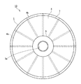
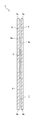
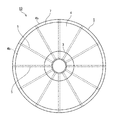
本技術が適用されたリール部材1を、図1、図2に示す。図1はリール部材1の一実施形態を示す正面図であり、図2はリール部材1の断面図である。リール部材1は、テープ状の接着フィルム2が巻回される巻芯3と、巻芯3の両側に設けられた一対のリールフランジ4を備える。また、リール部材1は、リールフランジ4の内側面4aに、当該内側面4aより突出し、当該リールフランジ4の中心側から周縁側にかけて延在する複数のリブ5が形成されている。
[Reel member]
The
[巻芯]
巻芯3は、円筒形状をなし、後述する接着フィルム2の幅よりも若干大きい幅を有する。また、巻芯3は、中心部にリール部材1を回転駆動する図示しない回転装置が挿通する挿通口3aが形成されている。そして、巻芯3は、両側は一対のリールフランジ4が接続され、リールフランジ4と一体に回転される。
[Core]
The winding
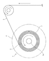
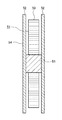
図3に示すように、巻芯3には、周面に接着フィルム2が多重に巻回されてなる巻装フィルム7が設けられる。巻装フィルム7は両側面が一対のリールフランジ4によって支持され、巻崩れの防止が図られている。なお、巻芯3の直径は適宜設計することができ、特に制限はないが、一例として40〜160mmとすることができる。
As shown in FIG. 3, the
[リールフランジ]
一対のリールフランジ4は、巻芯3に接着フィルム2が多重に巻回された巻装フィルム7を支持するものであり、例えばプラスチック材料を用いて円盤状に形成されている。また、リールフランジ4は、後述するリブ5が外面から視認できる程度に透過性があることが好ましい。また、リールフランジ4は、巻装フィルム7と接する面に、静電処理を施すようにしてもよい。静電処理を施す方法としては、例えば、ポリチオフェン等の化合物を塗布する方法が挙げられる。なお、リールフランジ4の直径は巻芯3の直径や接着フィルム2の長さ等に応じて適宜設計することができ、特に制限はないが、一例として90〜300mmとすることができる。
[Reel flange]
The pair of
[リブ]
図1に示すように、リールフランジ4の内側面4aには、リールフランジ4の中心側から周縁側にかけて延在する複数のリブ5が設けられている。より具体的には、リブ5は、内側面4aにおける巻芯3との接合部から周縁部4bにかけて直線状に延在し、例えば30°の等間隔をもって12本ずつ設けられている。なお、リブ5の長さはリールフランジ4の直径や巻芯3の直径等に応じて適宜設計することができる。リブ5の長さはフランジの内面(接着フィルムが巻き取られる面)において巻芯まで到達していることが、接着フィルムの巻き回しが開始から終了まで同条件で行うことができることから好ましく、一例として、(フランジの直径−巻芯の直径)/2とすることができる。巻芯近傍までリブが存在していれば、同様の効果を得ることができる。また、後述するように、リブが巻芯を貫通して巻芯の内側まで存在していてもよく、その場合は、上式に、巻芯の径の2〜45%を加算した長さとすることができる。リブ5の長さはフランジと巻芯の径の組み合わせによって定まり、リブ5の長さはフランジの半径未満になるが、一例として、25〜135mmとすることができる。
[rib]
As shown in FIG. 1, a plurality of
リール部材1は、リブ5の本数が少ないほど、リブ5と巻装フィルム7の側面との接触面積が減り、巻き取り時の貼り付きや引き出し時のブロッキングを防止する上で有利となるが、リブ5の間隔が拡がり、脱落のリスクが大きくなる。そのため、リブ5の形成本数は6本以上とすることが好ましく、12本以上とすることがさらに好ましい。リブ5の本数は、多くなれば製造難易度が高くなるが、リブ5の間隔が狭くなるため、リブ5間で接着フィルム2がずれる余地が少なくなる。そのため、リブ5の本数は、フィルム幅や長さ、バインダー樹脂のはみ出しやすさといった複合的な要因を考慮して選択すればよい。リール部材1の本数以外の他の設計因子も同様である。リブ本数が多すぎると、製造容易性が損なわれる虞があるため、36本以下とすることが好ましく、24本以下とすることがより好ましい。
As the number of
また、脱落の発生リスクを全周にわたって均等に低下させる上では、各リブ5は周方向に等間隔に設けられていることが好ましい。
Further, in order to reduce the risk of falling off evenly over the entire circumference, it is preferable that the
リールフランジ4のリブ5の高さH、すなわち断面視においてリールフランジ4の内側面4aからリブ5の最頂部までの突出量の上限は、0.10mm未満が好ましく、0.08mm以下がより好ましく、0.05mm以下が更により好ましい。リブ5の高さHが0.10mm以上となると、接着フィルム2の幅に対して両リールフランジ4間のスペースが広がり、脱落が発生しやすくなる。また、リブの高さHの下限は、0.01mm以上が好ましく、0.015mm以上がより好ましく、0.02mm以上が更により好ましい。リブ5の高さHが0.01mm未満となると、接着剤層の貼り付きやブロッキングを抑制することが困難となる。
The height H of the
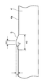
リブ5は、図4に示すように、リールフランジ4の内側面4aから隆起した部位であり、内側面4aの中心側から周縁側にかけて線状に形成されている。リブ5は、断面視において、接着フィルム2と接触する頂部幅W1が、リールフランジ4の内側面4aと接する基部幅W2よりも狭い。例えばリブ5は、台形状に形成されている。リブ5は、図4に示すように、左右対称形状としてもよく、左右対称形状でなくともよい。また、リブ5は、長さ方向において、左右対称形状とする領域と左右非対称形状とする領域が混在していてもよい。また、リブ5は、断面視において弧状や半円形状であってもよいが、辺が認識できる方が品質管理上は好ましい。形状の自由度は、リブが設けられているフランジの設計自由度が高まる点からは、好ましい。
As shown in FIG. 4, the
リブ5の頂部とは、断面視において、巻装フィルム7と接触する部位をいい、頂部幅W1とは、リブ5の頂部におけるリブ5の延在方向と直交する方向の距離をいう。
The top of the
リブ5の頂部は巻装フィルム7と接触し得る部位であり、接着フィルム2をリール部材1に巻き取る際における接着剤層の貼り付きや、接着フィルム2を引き出す際におけるブロッキングを抑制する上では、リブ頂部幅W1は短い方が好ましい。具体的にはリブ頂部幅W1の上限は、0.80mm以下が好ましく、より好ましくは0.60mm以下とすることで、貼り付きやブロッキングを効果的に抑制することができる。
The top of the
一方、リブ5の頂部は巻装フィルム7の側面に接触することで、接着フィルムの引き出し時において接着フィルム2の巻装フィルム7からの脱落を防止する。そのため、リブ頂部幅W1が短すぎると、その分脱落のリスクが増える。そのため、リブ頂部幅W1の下限は、0.10mm以上が好ましく、より好ましくは0.20mm以上とすることで、脱落を効果的に抑制することができる。
On the other hand, the top of the
リブ5の傾斜角度θは、90°未満であれば特に限定されないが、成形性に優れ、且つ巻装フィルム7との接触面積の制御のしやすさといった点で、2°〜88°の範囲で適宜選択することができる。リブ5の傾斜角度が小さいほど平坦な面に近づくことから、脱落防止に適していると考えられる。具体的に、傾斜角度は45°以下とすることで平坦な面に近づけることができ、30°以下が好ましく、15°以下がより好ましく、10°以下とすることがさらにより好ましい。一方、角度が小さすぎると貼りつきやブロッキングが発生しやすくなり、またリブ5の成形性が低下する等歩留まりへの影響も懸念されるため、上述のように2°以上が好ましく、3°以上がより好ましく、5°以上がさらにより好ましい。
The inclination angle θ of the
また、リブ5の基部とは、断面視において、リールフランジ4の内側面4aと接するリブ5の両端部間の部位をいい、リブ基部幅W2とは、リブ5の基部におけるリブ5の延在方向と直交する方向の距離をいう。リブ5の基部幅W2は、頂部幅W1よりも広く、リブ5の高さH及び傾斜角θによって規定される。リブ高さH及びリブ頂部幅W1が一定ならば、傾斜角θが大きいほどリブ5の基部幅W2は短くなり、傾斜角θが小さいほどリブ5の基部幅W2は長くなる。また、リブ5の傾斜角θ及びリブ頂部幅W1が一定ならば、リブ高さHが高くなるほどリブ5の基部幅W2は長くなり、リブ高さHが低くなるほどリブ5の基部幅W2は短くなる。
Further, the base portion of the
具体的に、上述したリブ頂部幅W1の上限並びに下限、及び傾斜角θの上限並びに下限から、リブ基部幅W2を定めることができる。一例として、W1<W2の条件を満たしたうえで、リブ基部幅W2が大きすぎるとリブの本数が増やしにくくなるので、リブ基部幅W2の上限は5mm以下、好ましくは4mm以下、より好ましくは3mm以下、更により好ましくは2.5mm以下とすることができる。また、リブ基部幅W2が小さすぎると寸法精度の再現性が難しくなるので、リブ基部幅W2の下限は0.6mm以上、好ましくは0.8mm以上、より好ましくは1mm以上となる。本技術の効果を十分に発揮させるためには、これらの全ての条件が満たされることが好ましい。 Specifically, the rib base width W2 can be determined from the upper and lower limits of the rib top width W1 and the upper and lower limits of the inclination angle θ described above. As an example, if the condition W1 <W2 is satisfied and the rib base width W2 is too large, it is difficult to increase the number of ribs. Therefore, the upper limit of the rib base width W2 is 5 mm or less, preferably 4 mm or less, more preferably 3 mm. Below, it can be even more preferably 2.5 mm or less. Further, if the rib base width W2 is too small, the reproducibility of dimensional accuracy becomes difficult. Therefore, the lower limit of the rib base width W2 is 0.6 mm or more, preferably 0.8 mm or more, and more preferably 1 mm or more. In order to fully exert the effect of the present technology, it is preferable that all of these conditions are satisfied.
リール部材1は、リブ5の形成本数、接着フィルム2の幅や長さ、バインダー樹脂のはみ出しやすさといった複合的な要因を考慮して、リブ5高さH、リブ頂部幅W1、傾斜角度θの各要素を、上述した範囲において最適に組み合わせることにより、接着剤層の貼り付きやブロッキングを抑制するとともに、細幅化された接着フィルム2においてもリールフランジ4−巻芯3間のスペースへの脱落を防止することができ、リブ5を備えつつ、リブ無しのリールフランジと同等の効果を奏することができる。なお、本技術は、細幅化された接着フィルム2において効果を発現しやすいものであるが、細幅化された接着フィルム2を用いたものに限定されるものではない。
The
このようなリール部材1としては、例えばリブ5高さH:0.02mm、リブ頂部幅W1:0.5mm、リブ基部幅W2:0.9mm、傾斜角度θ:5.7°、リブ本数:12本としたものを例示できる。なお、リブ本数は24としてもよい。
Examples of such a
また、リール部材1としては、例えばリブ5高さH:0.05mm、リブ頂部幅W1:0.5mm、リブ基部幅W2:1.5mm、傾斜角度θ:5.7°、リブ本数:12本としたものを例示できる。なお、リブ本数は24としてもよい。
Further, as the
ここで、上述したように、リールフランジ4のリブ5の高さHは、断面視において、リールフランジ4の内側面4aからリブ5の最頂部までの突出量をいう。リブ5の高さHの測定方法としては、リールフランジ4を巻芯3から外し、ガラス板などの上にフランジのリブ側を載置し、必要であれば液状接着剤等で固定した後、頂部W1と接触している長さとして測定することができる。もしくは、離型可能な液状接着剤を載せ、平板なガラス板を押し付け、硬化後に剥離し、その転写物を測定してもよい。あるいは、リールフランジ4を樹脂等で固定し断面研磨機で測定断面を研磨した後、測定することができる。なお、リブ5の高さHの測定手法を応用して、リブ5の頂部幅W1や基部幅W2、リブ5の傾斜角度θを測定することもできる。なお、リブ5の高さHの測定は、破壊検査により行ってもよい。
Here, as described above, the height H of the
このようなリブ5を備えたリールフランジ4は、射出成形、押出し成形等の成形法や切削加工等の公知の製造方法によって形成することができる。
The
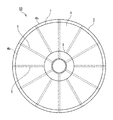
[リブ変形例]
図5に示すように、各リブ5は、巻芯3と対向する位置まで延在して形成してもよい。これにより、リブ5が一体形成されるリールフランジ4全体、もしくはリール部材1全体の加工性や再現性、歩留まりが高まる効果が期待できる。すなわち、リールフランジ4の成形時に金型に溶融した樹脂を流し込む、またはその後に金型から取り出す際などに、巻芯3と対向する位置まで延在するリブとして、一定量の樹脂が存在することで、作業性が増し、リールフランジ4の形状を安定化させることができる。その他、樹脂成形の制約を取り除き、金型の設計自由度を高める効果も期待できる。
[Rib deformation example]
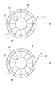
As shown in FIG. 5, each
リールフランジ4は、全てのリブ5において巻芯3と対向する位置まで延在させなくともよい。これにより、リールフランジ4を形成する樹脂量を削減できる。例えば、図6に示すように、1本おきに巻芯3と対向する位置まで延在するリブ5と巻装フィルム7と対向し得る位置にのみ延在するリブ5が形成されていてもよい。このように規則性が存在することが、品質検査や再現性の点からは望ましいが、性能を満足するのであれば、このような規則性が存在していなくともよい。規則性の有無に関わらず、巻芯3と対向する位置まで延在するリブ5と巻装フィルム7と対向し得る位置にのみ延在するリブ5が混在するリールフランジ4は、外観で区別しやすくなるため、リール部材1の識別性が高められているためである。そのため、上述したように、リールフランジ4は透明でもよく、リブ5が視認できる程度の透過性であることが好ましい。
The
巻芯3と対向する位置まで延在するリブ5は、巻芯3と対向する位置において、巻装フィルム7と対向し得る位置における幅よりも狭くなってもよい。これにより、リールフランジ4を形成する樹脂量を削減できる。一方、巻芯3と対向する位置まで延在するリブ5の頂部幅は、巻装フィルム7と対向し得る位置における頂部幅よりも広くなってもよい。加工がしやすくなるからである。
The
同様に、巻芯3と対向する位置まで延在するリブ5は、リブの高さや、断面形状が巻装フィルム7と対向する位置と異なるように形成してもよい。例えば、巻装フィルム7と対向し得る位置に延在するリブ5を左右対称形状とし、巻芯3と対向する位置まで延在するリブ5を左右非対称形状とする、あるいは左右対称形状と左右非対称形状をこの逆としてもよい。また、巻装フィルム7と対向し得る位置にのみ延在するリブ5を左右対称形状とし、巻芯3と対向する位置まで延在するリブ5を左右非対称形状とする、あるいは左右対称形状と左右非対称形状をこの逆としてもよい。これによっても、リール部材1の外観上の識別性を向上させることができる。
Similarly, the
[リール部材の製造方法]
巻芯3と一対のリールフランジ4の材質は、例えば、熱可塑性樹脂等が挙げられる。ここで、熱可塑性樹脂としては、汎用樹脂の他、汎用エンプラ、スーパーエンプラ等が挙げられる。熱可塑性樹脂は、結晶性であっても、非結晶性であってもよい。汎用樹脂の例としては、ポリエチレン、ポリプロピレン、ポリスチレン等が挙げられる。汎用エンプラの例としては、ポリカーボネート、ポリアミド等が挙げられる。スーパーエンプラの例としては、ポリイミド、ポリアミドイミド等が挙げられる。寸歩精度を再現性よく得られる点からは、非結晶性樹脂が好ましい。また、経済性の観点から、汎用樹脂を用いることが好ましい。
[Manufacturing method of reel member]
Examples of the material of the winding
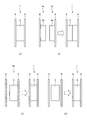
リール部材1の製造方法は、リール部材1を構成する成型品を作成する工程と、成型品がリール部材1の一部を構成する場合には、成型品同士を固着することで、リール部材1を作製する工程とを含む。具体的には、リール部材1は、金型成型により作製することができる。
The method for manufacturing the
図7(a)に示すように、リール部材1は、金型を用いてリール部材1全体を一体成型してもよい。
As shown in FIG. 7A, the
また、図7(b)に示すように、リール部材1は、2つの成型品1aを成型し、これらを固着することにより作製してもよい。成型品1aは、接着フィルムを巻き付け可能な分割巻芯部3bと、分割巻芯部3bの回転軸方向の一方の端部に一体成型されたリールフランジ4とを有する。また、分割巻芯部3bは、巻芯3を回転軸と垂直な方向に均等に2分割した形状を有する。すなわち、巻芯3は、回転軸方向に連結された複数の分割巻芯部3bによって構成される。成型品1a同士を固着する方法は特に制限されず、例えば超音波溶着やインパルス溶着が挙げられる。
Further, as shown in FIG. 7B, the
また、図7(c)に示すように、リール部材1は、成型品1b、リールフランジ4を成型し、これらを固着することにより作製してもよい。成型品1bは、巻芯3と、巻芯3の回転軸方向の一方の端部に一体成型されたリールフランジ4とを有する。また、リールフランジ4と巻芯3とを固着する方法は特に制限されないが、例えば超音波溶着やインパルス溶着が好ましいが、接着テープ(接着剤)等を使用してもよい。
Further, as shown in FIG. 7C, the
図7(d)に示すように、リール部材1は、2つのリールフランジ4、巻芯3を個別に成型し、これらを固着することで作製してもよい。この例では、2つのリールフランジ4、巻芯3を個別に成型するので、2つのリールフランジ4、巻芯3を精度よく成型できる。また、2つのリールフランジ4と巻芯3とを固着する方法は特に制限されないが、例えば超音波溶着やインパルス溶着が挙げられる。別の手法としては、組み立て式の形状でリールフランジ4や巻芯3の成形品を作成し、これらを組み立てる際に接着剤や接着フィルムで固着してもよい。このようにすることで、巻芯3に継ぎ目がなくなり、巻き回しが容易になる効果が期待できる。
As shown in FIG. 7D, the
[接着フィルム巻装体]
接着フィルム巻装体10は、上述したリール部材1と、接着フィルム2が巻芯3に巻回されてなる巻装フィルム7を備える。
[Adhesive film winding body]
The adhesive
[接着フィルム]
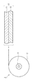
巻芯3に巻回される接着フィルム2は、図8に示すように、ベースフィルム11と、ベースフィルム11に支持された絶縁性バインダーからなる接着剤層12とを有する。
[Adhesive film]
As shown in FIG. 8, the
接着フィルム2の長さは、特に限定されることはないが、接着フィルム巻装体の製品として必要なフィルム長さとして、接着フィルム2の長さの下限は、5m以上、好ましくは10m以上、より好ましくは50m以上のものを好適に用いることができる。一方で、フィルム長さが長くなるほど、巻芯付近の接着フィルム2に掛かる巻き締りによる圧力が大きくなり、接着材層のはみ出しによるブロッキングの発生リスクが高まる。そのため、長さの上限は500m以下、400m以下、300m以下のものを好適に用いることができる。
The length of the
また、接着フィルム2の幅は、特に限定されることはないが、近年の電子機器の小型化の要請により、実装領域も狭小化し、これに伴い、接着フィルムの細幅化が求められている。このような細幅化に応じて、接着フィルム2は、上限幅が例えば0.6mm以下、0.5mm以下、0.4mm以下のものを好適に用いることができ、下限幅が0.1mm以上ものを好適に用いることができる。
Further, the width of the
このような細幅化、長尺化に応じた接着フィルム2としては、例えば幅0.6mm、長さ350mのものが例示される。長尺な接着フィルムを作製する方法としては、例えば、短い接着フィルム(例えば100m程度)を複数作製し、これらを連結する方法が挙げられる。なお、巻芯3と接着フィルム2は、リード及び繋ぎテープ(それぞれ図示せず)を用いて固定してもよい。
Examples of the
ベースフィルム11は、テープ状に成型され、接着剤層12を支持する支持フィルムである。ベースフィルム11としては、例えば、PET(Poly Ethylene Terephthalate)、OPP(Oriented Polypropylene)、PMP(Poly-4-methylpentene-1)、PTFE(Polytetrafluoroethylene)などが挙げられる。また、ベースフィルム11は、少なくとも接着剤層12側の面が例えばシリコーン樹脂により剥離処理されたものを好適に用いることができる。
The
なお、本技術では、ベースフィルム11と接着剤層12が分離可能である接着フィルム2を想定しているが、ベースフィルムに接着剤層が分離不可能になっている接着フィルムにも適用は可能である。このような接着フィルムにおいても、例えば、細幅のものであれば脱落の問題は同様に発生するからである。そのため接着剤層は粘着だけの効果を発揮する層であってもよい。
Although the present technology assumes an
ベースフィルム11の厚みは、特に限定されるものではない。ベースフィルム11の厚みの下限は、実用上3μm以上であればよく、安定して分離させる上で10μm以上が好ましく、25μm以上であることがより好ましく、38μm以上であることが更により好ましい。ベースフィルム11の厚みの上限は、厚すぎると過度に接着剤層12に圧力がかかりすぎることが懸念されるため、200μm以下であることが好ましく、100μm以下であることがより好ましく、75μm以下であることが更により好ましい。50μm以下としてもよい。
The thickness of the
一方、接着剤層12を形成する絶縁性バインダー(樹脂組成物)は、公知の絶縁性バインダーを用いることができ、接着フィルム2の用途、フィラーの有無等に応じて適宜選択され、熱可塑性樹脂組成物、高粘度粘着性樹脂組成物、硬化性樹脂組成物から形成することができる。例えば、接着フィルム2を電子部品の実装等に使用する接着材とする場合、WO2018/074318A1公報に記載の絶縁性樹脂層等を形成する樹脂組成物と同様とすることができる。また、絶縁性樹脂層は複数積層されていてもよい。また、絶縁性樹脂層が複数積層された積層体は、全ての層が同じ配合である必要はない。
On the other hand, as the insulating binder (resin composition) forming the
例えば、硬化性樹脂組成物の重合開始剤としては熱重合開始剤を使用してもよく、光重合開始剤を使用してもよく、それらを併用してもよい。例えば、熱重合開始剤として熱カチオン系重合開始剤、熱重合性化合物としてエポキシ樹脂を使用し、光重合開始剤として光ラジカル重合開始剤、光重合性化合物としてアクリレート化合物を使用する。熱重合開始剤として、熱アニオン系重合開始剤を使用してもよい。熱アニオン重合開始剤としては、イミダゾール変性体を核としその表面をポリウレタンで被覆してなるマイクロカプセル型潜在性硬化剤を用いることが好ましい。 For example, as the polymerization initiator of the curable resin composition, a thermal polymerization initiator may be used, a photopolymerization initiator may be used, or they may be used in combination. For example, a thermal cationic polymerization initiator is used as the thermal polymerization initiator, an epoxy resin is used as the thermal polymerizable compound, a photoradical polymerization initiator is used as the photopolymerization initiator, and an acrylate compound is used as the photopolymerizable compound. A thermal anion-based polymerization initiator may be used as the thermal polymerization initiator. As the thermal anionic polymerization initiator, it is preferable to use a microcapsule type latent curing agent having an imidazole modified product as a nucleus and the surface thereof coated with polyurethane.
硬化性樹脂組成物で形成される接着剤層全体としての所定温度での溶融粘度、最低溶融粘度は、特に制限はなく、一例として、WO2018/074318A1公報の絶縁性樹脂層等に準じてもよいが、これに限定されるものではない。溶融粘度は、保存温度、使用時環境温度などにおけるはみ出しの発生に支配的な因子であると考えられる。最低溶融粘度は高すぎると加圧して使用する際の押し込みや流動に懸念が発生するため、対象物によって調整すればよい。この最低溶融粘度は、一例として回転式レオメータ(TA instrument社製)を用い、測定圧力5gで一定に保持し、直径8mmの測定プレートを使用し求めることができ、より具体的には、温度範囲30〜200℃において、昇温速度10℃/分、測定周波数10Hz、前記測定プレートに対する荷重変動5gとすることにより求めることができる。所定温度での溶融粘度は温度を固定することで、最低溶融粘度と同様に測定することができる。また、溶融粘度はTMA(Thermomechanical Analysis,熱機械分析)による引張測定で測定してもよい。なお、最低溶融粘度の調整は、溶融粘度調整剤、チキソトロピック剤の種類や配合量、樹脂組成物の調整条件の変更などにより行うことができる。 The melt viscosity and the minimum melt viscosity of the adhesive layer formed of the curable resin composition as a whole at a predetermined temperature are not particularly limited, and may be, for example, according to the insulating resin layer of WO2018 / 074318A1. However, it is not limited to this. The melt viscosity is considered to be a dominant factor in the occurrence of protrusion at the storage temperature, the environmental temperature during use, and the like. If the minimum melt viscosity is too high, there is a concern about pushing and flow when using under pressure, so it may be adjusted according to the object. This minimum melt viscosity can be determined by using a rotary rheometer (manufactured by TA instrument) as an example, keeping the measurement pressure constant at 5 g, and using a measurement plate having a diameter of 8 mm. More specifically, the temperature range. It can be obtained by setting the temperature rise rate at 10 ° C./min, the measurement frequency at 10 Hz, and the load fluctuation with respect to the measurement plate at 30 to 200 ° C. The melt viscosity at a predetermined temperature can be measured in the same manner as the minimum melt viscosity by fixing the temperature. Further, the melt viscosity may be measured by tensile measurement by TMA (Thermomechanical Analysis). The minimum melt viscosity can be adjusted by changing the type and amount of the melt viscosity adjuster and thixotropic agent, and the adjustment conditions of the resin composition.
絶縁性バインダーには、接着フィルム2の用途に応じて、導電性の付与、その他、粘度調整剤、チキソトロピック剤、重合開始剤、カップリング剤、難燃化剤等の機能を付与する目的で、有機フィラーや無機フィラー、及びこれらを複合したフィラー(有機無機混合フィラー)といったフィラーを含有させてもよい。これは例えば、通電用途のための導電性フィラーやギャップスペーサー用途としての絶縁性フィラー、あるいは、光散乱性やつや消しなどの光学用途のフィラー又は顔料などの着色目的のために使用されるフィラー等が挙げられ、使用目的に合わせて適宜調整すればよい。フィラーの用途は限定されず、また、各用途に係る公知のフィラーは多種にわたるため例示しない。フィラーは1種類に限定されず、複数種類のフィラーを混在させてもよい。また、フィラーの大きさ(平均粒子径)も特に限定されない。
Depending on the use of the
[接着フィルムの製造方法]
接着フィルム2は、上述した各バインダー樹脂成分及び必要に応じて含有されるフィラーと混合させたバインダー樹脂組成物を塗布法によりベースフィルム11上に成膜し、乾燥させることにより製造することができる。なお、フィラーは、バインダー樹脂成分をベースフィルム11上に成膜した後に設けてもよい。また、接着フィルム2は、ベースフィルム11と反対側の面にさらに剥離フィルムが設けられていてもよい。
[Manufacturing method of adhesive film]
The
図3に示すように、接着フィルム2は、ガイドローラーにガイドされながらリール部材1の巻芯3に多重に巻回されることにより、巻装フィルム7が形成される。巻装フィルム7は両側面が一対のリールフランジ4によって支持され、巻崩れの防止が図られている。これにより、接着フィルム巻装体10を得る。
As shown in FIG. 3, the
ここで、リール部材1は、リブ5の断面視において、接着フィルム2と接触する頂部幅W1がリールフランジ4の内側面4aと接する基部幅W2よりも狭い。これにより、リール部材1は、接着フィルム2の細幅化によっても、接着剤層12の貼り付きを防止することができる。また、接着フィルム2を引き出す際においても、ブロッキング及び脱落を抑制することができる。
Here, in the cross-sectional view of the
また、上述したように、リール部材1は、リブ5の高さHを0.01mmより大きく、0.10mm未満とすることが好ましい。また、リブ頂部幅W1は0.10mm以上0.80mm以下とすることが好ましい。さらに、リブ5の傾斜角度θは、2°以上88°以下とすることが好ましく、45°以下とすることで、リブ5の形状を緩やかに隆起させ、リールフランジ4の内側面4aをより平坦面に近づけることができる。
Further, as described above, in the
このように、リール部材1は、リブ5の形成本数、接着フィルム2の幅や長さ、バインダー樹脂のはみ出しやすさといった複合的な要因を考慮して、リブ5の高さH、リブ頂部幅W1、傾斜角度θの各要素を、上述した範囲において最適に組み合わせることにより、接着剤層の貼り付きやブロッキングを抑制するとともに、細幅化された接触においても両リールフランジ4間のスペースへの脱落を防止することができ、リブ5を備えつつ、リブ無しのリールフランジと同等の効果を奏することができる。
As described above, the
[接着剤層のタック]
なお、接着フィルム巻装体10における接着剤層12の貼り付きや脱落を防止するリブ5の寸法設計は、接着剤層12の粘着力(タック)によっても影響され得る。すなわち、タックが大きい場合、巻装フィルム7において接着フィルム2のズレは生じ難く、脱落を抑制するリブ高さHの許容範囲は広がる。一方、タックが大きいと、接着剤層12がリブと接触することによって起きる貼り付きやブロッキングのリスクは高まるため、リブ頂部幅W1やリブ本数の許容範囲は狭まる。
[Adhesive layer tack]
The dimensional design of the
反対に、タックが小さい場合、巻装フィルム7において接着フィルム2のズレは生じ易くなり、脱落を抑制する上でリブ高さHの許容範囲は狭まる。一方、タックが小さいと、接着剤層12がリブと接触することによって起きる貼り付きやブロッキングのリスクは下がるため、リブ頂部幅W1やリブ本数の許容範囲は広がる。
On the contrary, when the tack is small, the
また、タックが与える影響は、接着フィルム2の幅によっても変動する。同じタックを有する接着フィルム2であっても、フィルム幅が狭くなると、捩れが生じ易くなり、貼り付きや脱落のリスクは高まる。また、フィルム幅が狭まるほど、単位面積が小さくなるため、相対的にタックの影響が大きくなる。そのため、接着フィルム2のように、ベースフィルム11から剥離して接着剤層12を使用する接着フィルムにおいては、タックの影響度は大きいと言える。本技術は、フィルム幅によらずその効果を奏するものであるが、特にフィルム幅が狭いもの(例えば0.6mm以下、好ましくは、0.5mm以下、より好ましくは0.4mm以下)において、顕著に効果を発揮し得る。
The effect of tack also varies depending on the width of the
なお、接着剤層12タックの測定方法例としては、JIS Z 0237に準じて測定することができ、また、JIS Z 3284−3又はASTM D 2979―01に準じてプローブ法によりタック力として測定することもできる。例えば、タック試験機(TACII、株式会社レスカ)を用いて、試料台のシリコンラバーの受け台上に接着剤層12を測定面がプローブ面を向くように載置する。次にタック試験機の円柱状の直径5mmのプローブ(ステンレス製鏡面仕上げ)を測定面の上方にセットし、押し付け速度30mm/minでプローブを測定面に接触させ、加圧力196.25gf、加圧時間1.0secで加圧し、引き剥がし速度120mm/minで測定面から2mm引き剥がしたときにプローブが測定面の粘着力によって受ける抵抗を荷重値として測定し、プローブを測定面から引き剥がすときの最大荷重をタック力(粘着力)とするこができる。測定数はN=2以上であることが好ましい。測定温度は23℃±5℃で計測することができる。
As an example of the method for measuring the
樹脂のはみ出しについては、特開2017−137188号に準じて測定することができる。最も樹脂がはみ出し易い試験条件で行ってもよく、比較的樹脂がはみ出し難い試験条件で行ってもよい。 The protrusion of the resin can be measured according to Japanese Patent Application Laid-Open No. 2017-137188. The test conditions may be such that the resin is most likely to squeeze out, or the test conditions may be such that the resin is relatively difficult to squeeze out.
接着フィルムの引き出し試験は、特開2016−160027号に準じて、引出試験機エー・アンド・デイ社製テンシロンを用いて接着フィルムのテープ外れ率を測定することができる。 In the withdrawal test of the adhesive film, the tape detachment rate of the adhesive film can be measured by using a drawing tester A & D Co., Ltd. Tencilon according to Japanese Patent Application Laid-Open No. 2016-160027.
1 リール部材、2 接着フィルム、3 巻芯、4 リールフランジ、4a 内側面、4b 周縁部、5 リブ、7 巻装フィルム、10 接着フィルム巻装体、11 ベースフィルム、12 接着剤層 1 Reel member, 2 Adhesive film, 3 Winding core, 4 Reel flange, 4a Inner surface, 4b Peripheral part, 5 ribs, 7 winding film, 10 Adhesive film winding body, 11 Base film, 12 Adhesive layer
Claims (9)
上記巻芯の両側に設けられた一対のリールフランジを備え、
上記リールフランジの内側面には、当該内側面より突出し、当該リールフランジの中心側から周縁側にかけて延在する複数のリブが形成され、
上記リブは、断面視において、上記接着フィルムと接触する頂部の幅が上記内側面と接する基部の幅よりも狭い
リール部材。 The core around which the adhesive film is wound and
It is equipped with a pair of reel flanges provided on both sides of the winding core.
On the inner surface of the reel flange, a plurality of ribs protruding from the inner surface and extending from the center side to the peripheral side of the reel flange are formed.
The rib is a reel member in which the width of the top portion in contact with the adhesive film is narrower than the width of the base portion in contact with the inner side surface in a cross-sectional view.
上記接着フィルムが上記巻芯に巻回されてなる巻装フィルムを備え、
上記リール部材は、上記請求項1〜6のいずれかに記載のリール部材である、
接着フィルム巻装体。 A reel member around which a tape-shaped adhesive film is wound, a reel member having a pair of reel flanges provided on both sides of the reel, and a reel member.
A winding film in which the adhesive film is wound around the core is provided.
The reel member is the reel member according to any one of claims 1 to 6.
Adhesive film winding body.
Priority Applications (7)
| Application Number | Priority Date | Filing Date | Title |
|---|---|---|---|
| JP2019211806A JP7595411B2 (en) | 2019-11-22 | 2019-11-22 | Reel parts, adhesive film rolls |
| KR1020247035972A KR20240160239A (en) | 2019-11-22 | 2020-11-18 | Reel member, and adhesive film wound body |
| TW109140212A TWI874492B (en) | 2019-11-22 | 2020-11-18 | Reel components, film roll package |
| PCT/JP2020/042932 WO2021100741A1 (en) | 2019-11-22 | 2020-11-18 | Reel member, and adhesive film wound body |
| US17/777,534 US12441580B2 (en) | 2019-11-22 | 2020-11-18 | Reel member and adhesive film winding body |
| CN202080080149.9A CN114728754A (en) | 2019-11-22 | 2020-11-18 | Reel parts, adhesive film winding mounting body |
| KR1020227016915A KR102724799B1 (en) | 2019-11-22 | 2020-11-18 | Absence of reel, adhesive film recommended |
Applications Claiming Priority (1)
| Application Number | Priority Date | Filing Date | Title |
|---|---|---|---|
| JP2019211806A JP7595411B2 (en) | 2019-11-22 | 2019-11-22 | Reel parts, adhesive film rolls |
Publications (3)
| Publication Number | Publication Date |
|---|---|
| JP2021080098A true JP2021080098A (en) | 2021-05-27 |
| JP2021080098A5 JP2021080098A5 (en) | 2023-05-22 |
| JP7595411B2 JP7595411B2 (en) | 2024-12-06 |
Family
ID=75964142
Family Applications (1)
| Application Number | Title | Priority Date | Filing Date |
|---|---|---|---|
| JP2019211806A Active JP7595411B2 (en) | 2019-11-22 | 2019-11-22 | Reel parts, adhesive film rolls |
Country Status (6)
| Country | Link |
|---|---|
| US (1) | US12441580B2 (en) |
| JP (1) | JP7595411B2 (en) |
| KR (2) | KR20240160239A (en) |
| CN (1) | CN114728754A (en) |
| TW (1) | TWI874492B (en) |
| WO (1) | WO2021100741A1 (en) |
Cited By (1)
| Publication number | Priority date | Publication date | Assignee | Title |
|---|---|---|---|---|
| WO2026058622A1 (en) * | 2024-09-13 | 2026-03-19 | デクセリアルズ株式会社 | Reel member, and adhesive film wound body |
Families Citing this family (3)
| Publication number | Priority date | Publication date | Assignee | Title |
|---|---|---|---|---|
| TWI767131B (en) | 2018-07-18 | 2022-06-11 | 日商美克司股份有限公司 | strapping belt |
| JP7325706B2 (en) * | 2018-07-18 | 2023-08-15 | マックス株式会社 | Binding tape, binding method, tape wound body and reel |
| US20240299856A1 (en) * | 2023-03-10 | 2024-09-12 | Nelson Companies One, LLC | Balloon weight and ribbon assembly with adhesive film peel-assist feature |
Citations (3)
| Publication number | Priority date | Publication date | Assignee | Title |
|---|---|---|---|---|
| WO2007148593A1 (en) * | 2006-06-21 | 2007-12-27 | Hitachi Chemical Company, Ltd. | Reel |
| WO2011118503A1 (en) * | 2010-03-23 | 2011-09-29 | 日立化成工業株式会社 | Adhesive tape reel |
| WO2017026404A1 (en) * | 2015-08-10 | 2017-02-16 | デクセリアルズ株式会社 | Reel member, film container, and reel member manufacturing method |
Family Cites Families (43)
| Publication number | Priority date | Publication date | Assignee | Title |
|---|---|---|---|---|
| US851366A (en) * | 1906-11-01 | 1907-04-23 | Frank Mossberg | Reel. |
| US962654A (en) * | 1909-06-14 | 1910-06-28 | Frank Mossberg Company | Reel. |
| US1341817A (en) * | 1919-09-15 | 1920-06-01 | Mossberg Pressed Steel Corp | Reel or beam |
| US1658009A (en) * | 1926-05-10 | 1928-01-31 | Crocker Wheeler Electric Mfg C | Sheet-metal spool |
| US1981138A (en) * | 1927-10-11 | 1934-11-20 | Western Electric Co | Reel |
| US1981139A (en) * | 1928-06-26 | 1934-11-20 | Western Electric Co | Reel |
| US2266903A (en) * | 1939-10-12 | 1941-12-23 | Nat Standard Co | Wire reel |
| US2465573A (en) * | 1947-03-07 | 1949-03-29 | Charles W Hayner | Spool |
| US2985402A (en) * | 1958-02-26 | 1961-05-23 | True Temper Corp | Spool construction |
| US3099414A (en) * | 1961-02-27 | 1963-07-30 | Thomas S Kuika | Tape reel having friction reducing means |
| US3462097A (en) * | 1967-03-17 | 1969-08-19 | Dare Products Inc | Unitary spool assembly |
| DE2016320B2 (en) * | 1970-04-06 | 1971-06-03 | Mittelrheimsche Metallgießerei, Heinnch Beyer KG, 5470 Andernach | CABLE REEL |
| FR2252757A5 (en) * | 1973-11-23 | 1975-06-20 | Stoquelet Michel | |
| US3966139A (en) * | 1974-08-19 | 1976-06-29 | Owens-Corning Fiberglas Corporation | Textile serving spool |
| JPH023475Y2 (en) * | 1985-03-08 | 1990-01-26 | ||
| US4997142A (en) * | 1989-04-28 | 1991-03-05 | Grant Plastics, Inc. | Plastic reel |
| US5474254A (en) * | 1994-11-08 | 1995-12-12 | Faulkner Fabricators, Inc. | Spool and method of making same |
| CN1152383C (en) * | 1996-05-30 | 2004-06-02 | 可隆株式会社 | Reel for winding photosensitive film |
| US6450441B2 (en) * | 1998-02-13 | 2002-09-17 | C. Robert Ripplinger | Twin sheet flanges for spools and reels |
| US6598825B2 (en) * | 1998-02-13 | 2003-07-29 | C. Robert Ripplinger | Simultaneous-access surfaces for reel-flange fasteners |
| US6003807A (en) * | 1998-02-13 | 1999-12-21 | Ripplinger; C. Robert | Corrugated, fracture-controlling flanges for spools and reels |
| US6435451B1 (en) * | 2000-10-19 | 2002-08-20 | Storage Technology Corporation | Compliant tape reel flanges |
| US6612474B2 (en) * | 2000-12-22 | 2003-09-02 | Kumud Shah | Hand-held tape dispenser with brake mechanism |
| US20040124305A1 (en) * | 2002-12-30 | 2004-07-01 | Harrison Huang | Tape dispenser with capacity of preventing tape being drawn back |
| US20040226857A1 (en) * | 2003-05-15 | 2004-11-18 | Wright Lance Cole | Apparatus to minimize paper particulate from paper based carrier tape reel |
| US7170130B2 (en) | 2004-08-11 | 2007-01-30 | Spansion Llc | Memory cell with reduced DIBL and Vss resistance |
| CN102070048B (en) * | 2006-06-21 | 2016-02-03 | 日立化成株式会社 | The method for winding of band |
| US7300017B1 (en) * | 2006-08-22 | 2007-11-27 | Tokusen Kogyo Co., Ltd. | Reel for metal linear material |
| KR101940349B1 (en) * | 2011-07-08 | 2019-01-18 | 히타치가세이가부시끼가이샤 | Reel for adhesive tape, tape roll, packaging, use of reel as reel for adhesive tape for winding adhesive tape, and method for manufacturing reel for adhesive tape |
| JP5930274B2 (en) * | 2011-12-05 | 2016-06-08 | デクセリアルズ株式会社 | Reel member and film container |
| JP5897942B2 (en) | 2012-03-15 | 2016-04-06 | デクセリアルズ株式会社 | Reel member, film winding method, film unwinding method |
| JP5982159B2 (en) * | 2012-04-06 | 2016-08-31 | デクセリアルズ株式会社 | Reel member, adhesive film winding method, adhesive film unwinding method |
| JP5905351B2 (en) * | 2012-07-04 | 2016-04-20 | デクセリアルズ株式会社 | Reel member and film container |
| US20150197409A1 (en) * | 2014-01-13 | 2015-07-16 | Domenico Caldieri | Reel/spool with handle and locating/stabilizing bump apparatus and a method thereof |
| US9637346B2 (en) * | 2014-05-15 | 2017-05-02 | Carris Reels, Inc. | Reels with slitted flanges |
| JP2016160027A (en) | 2015-02-27 | 2016-09-05 | デクセリアルズ株式会社 | Reel for adhesive film, and connected body used for the same |
| JP2017137188A (en) | 2016-02-05 | 2017-08-10 | デクセリアルズ株式会社 | Extrusion test method of film wound body |
| US10501277B2 (en) * | 2016-11-01 | 2019-12-10 | Kitaru Innovations Inc. | Brake assembly for a tape dispenser |
| US10544002B2 (en) * | 2016-11-01 | 2020-01-28 | Kitaru Innovations Inc. | Brake assembly for a tape dispenser |
| US10494217B2 (en) * | 2016-11-01 | 2019-12-03 | Kitaru Innovations, Inc. | Brake assembly for a tape dispenser |
| US10544003B2 (en) * | 2016-11-01 | 2020-01-28 | Kitaru Innovations Inc. | Brake assembly for a tape dispenser |
| US10584012B2 (en) * | 2018-03-09 | 2020-03-10 | Axjo Plastic Aktiebolag | Two-part and stackable cable spool arrangement |
| US11535482B1 (en) * | 2021-02-01 | 2022-12-27 | James F. C. Swanson | Bungee spool |
-
2019
- 2019-11-22 JP JP2019211806A patent/JP7595411B2/en active Active
-
2020
- 2020-11-18 US US17/777,534 patent/US12441580B2/en active Active
- 2020-11-18 CN CN202080080149.9A patent/CN114728754A/en active Pending
- 2020-11-18 WO PCT/JP2020/042932 patent/WO2021100741A1/en not_active Ceased
- 2020-11-18 KR KR1020247035972A patent/KR20240160239A/en active Pending
- 2020-11-18 KR KR1020227016915A patent/KR102724799B1/en active Active
- 2020-11-18 TW TW109140212A patent/TWI874492B/en active
Patent Citations (3)
| Publication number | Priority date | Publication date | Assignee | Title |
|---|---|---|---|---|
| WO2007148593A1 (en) * | 2006-06-21 | 2007-12-27 | Hitachi Chemical Company, Ltd. | Reel |
| WO2011118503A1 (en) * | 2010-03-23 | 2011-09-29 | 日立化成工業株式会社 | Adhesive tape reel |
| WO2017026404A1 (en) * | 2015-08-10 | 2017-02-16 | デクセリアルズ株式会社 | Reel member, film container, and reel member manufacturing method |
Cited By (1)
| Publication number | Priority date | Publication date | Assignee | Title |
|---|---|---|---|---|
| WO2026058622A1 (en) * | 2024-09-13 | 2026-03-19 | デクセリアルズ株式会社 | Reel member, and adhesive film wound body |
Also Published As
| Publication number | Publication date |
|---|---|
| US20230339720A1 (en) | 2023-10-26 |
| KR20220082910A (en) | 2022-06-17 |
| TWI874492B (en) | 2025-03-01 |
| KR102724799B1 (en) | 2024-10-31 |
| CN114728754A (en) | 2022-07-08 |
| JP7595411B2 (en) | 2024-12-06 |
| WO2021100741A1 (en) | 2021-05-27 |
| US12441580B2 (en) | 2025-10-14 |
| KR20240160239A (en) | 2024-11-08 |
| TW202138277A (en) | 2021-10-16 |
Similar Documents
| Publication | Publication Date | Title |
|---|---|---|
| WO2021100741A1 (en) | Reel member, and adhesive film wound body | |
| RU2759664C1 (en) | Method for manufacturing flexible fibre-optic tape and tape | |
| KR101240155B1 (en) | Electroconductive particle placement sheet and anisotropic electroconductive film | |
| CN1264941C (en) | Stripping film and adhesive film using stripping film | |
| CN100425424C (en) | Optical film and tis producing method and polaroid lens | |
| WO2021161815A1 (en) | Adhesive film production apparatus and reel bodies | |
| WO2007141899A1 (en) | Polycarbonate resin film and method for production thereof | |
| JP2022076616A (en) | Reel body, reel body manufacturing method, and article manufacturing method | |
| WO2021161814A1 (en) | Adhesive film production device and adhesive film production method | |
| KR20170102350A (en) | Reel, film connecting body, film winding mounting body and manufacturing method of film connecting body | |
| JPH04333457A (en) | Seamless belt with guide for preventing snaking | |
| JP6693161B2 (en) | Film connection body, film winding body, reel body, and method for manufacturing film connection body | |
| JP4271962B2 (en) | Chip carrier spacer base film | |
| WO2026058622A1 (en) | Reel member, and adhesive film wound body | |
| JP7443690B2 (en) | Adhesive tape reel | |
| TWI902762B (en) | Extrusion molding apparatus, film manufacturing system, and film manufacturing method | |
| HK1241838B (en) | Reel body, film connection body, film winding body, and manufacturing method for film connection body | |
| KR20230106199A (en) | Reel product including anisotropic conductive adhesive films winded therein | |
| CN108778648B (en) | Adhesive film cutting method, adhesive film and package | |
| TW202227271A (en) | Method for producing film | |
| JP2009060124A (en) | Chip carrier spacer base film | |
| KR20140132004A (en) | Adhesive film pasting method and adhesive film pasting device | |
| NZ766575B2 (en) | A method for producing a flexible optical fiber ribbon and said ribbon. | |
| JP2004074572A (en) | Heat treatment equipment for film | |
| JP2013142823A (en) | Light antireflection article |
Legal Events
| Date | Code | Title | Description |
|---|---|---|---|
| A621 | Written request for application examination |
Free format text: JAPANESE INTERMEDIATE CODE: A621 Effective date: 20221122 |
|
| A521 | Request for written amendment filed |
Free format text: JAPANESE INTERMEDIATE CODE: A523 Effective date: 20230512 |
|
| A131 | Notification of reasons for refusal |
Free format text: JAPANESE INTERMEDIATE CODE: A131 Effective date: 20231121 |
|
| A601 | Written request for extension of time |
Free format text: JAPANESE INTERMEDIATE CODE: A601 Effective date: 20240119 |
|
| A521 | Request for written amendment filed |
Free format text: JAPANESE INTERMEDIATE CODE: A523 Effective date: 20240321 |
|
| A131 | Notification of reasons for refusal |
Free format text: JAPANESE INTERMEDIATE CODE: A131 Effective date: 20240618 |
|
| A601 | Written request for extension of time |
Free format text: JAPANESE INTERMEDIATE CODE: A601 Effective date: 20240813 |
|
| A521 | Request for written amendment filed |
Free format text: JAPANESE INTERMEDIATE CODE: A523 Effective date: 20240930 |
|
| TRDD | Decision of grant or rejection written | ||
| A01 | Written decision to grant a patent or to grant a registration (utility model) |
Free format text: JAPANESE INTERMEDIATE CODE: A01 Effective date: 20241105 |
|
| A61 | First payment of annual fees (during grant procedure) |
Free format text: JAPANESE INTERMEDIATE CODE: A61 Effective date: 20241126 |
|
| R150 | Certificate of patent or registration of utility model |
Ref document number: 7595411 Country of ref document: JP Free format text: JAPANESE INTERMEDIATE CODE: R150 |