JP5773490B2 - Die push-up operation management system - Google Patents
Die push-up operation management system Download PDFInfo
- Publication number
- JP5773490B2 JP5773490B2 JP2011184278A JP2011184278A JP5773490B2 JP 5773490 B2 JP5773490 B2 JP 5773490B2 JP 2011184278 A JP2011184278 A JP 2011184278A JP 2011184278 A JP2011184278 A JP 2011184278A JP 5773490 B2 JP5773490 B2 JP 5773490B2
- Authority
- JP
- Japan
- Prior art keywords
- push
- die
- pin
- pot
- dicing sheet
- Prior art date
- Legal status (The legal status is an assumption and is not a legal conclusion. Google has not performed a legal analysis and makes no representation as to the accuracy of the status listed.)
- Active
Links
Images


Description
本発明は、ダイシングされたウエハが貼着された伸縮可能なダイシングシートを張ったウエハパレットを備えたダイ供給装置におけるダイ突き上げ動作を管理するダイ突き上げ動作管理システムに関する発明である。 The present invention relates to a die push-up operation management system for managing a die push-up operation in a die supply apparatus provided with a wafer pallet provided with a stretchable dicing sheet to which a diced wafer is attached.
近年、特許文献1(特開2010−129949号公報)に記載されているように、ダイを供給するダイ供給装置を部品実装機にセットして、部品実装機でダイを回路基板に実装するようにしたものがある。ダイ供給装置は、複数のダイに分割するようにダイシングされたウエハが貼着された伸縮可能なダイシングシートを張ったウエハパレットと、前記ダイシングシートの下方に配置された突き上げポットとを備え、吸着ノズルを下降させて前記ダイシングシート上のダイを吸着してピックアップする際に、突き上げポットをダイシングシートの下面に接触する所定の吸着位置まで上昇させて該ダイシングシートを該突き上げポットの上面に吸着した状態で、該突き上げポット内の突き上げピンを該突き上げポットの上面から上方に突出させることで、該ダイシングシートのうちの吸着しようとするダイの貼着部分を該突き上げピンで突き上げて該ダイの貼着部分を該ダイシングシートから部分的に剥離させながら、該吸着ノズルに該ダイを吸着して該ダイシングシートからピックアップするようにしている。 In recent years, as described in Patent Document 1 (Japanese Patent Laid-Open No. 2010-129949), a die supply device that supplies a die is set in a component mounter, and the die is mounted on a circuit board by the component mounter. There is something that was made. The die supply apparatus includes a wafer pallet having a stretchable dicing sheet on which a wafer diced so as to be divided into a plurality of dies is attached, and a push-up pot disposed below the dicing sheet. When picking up the die on the dicing sheet by lowering the nozzle, the push-up pot is raised to a predetermined suction position that contacts the lower surface of the dicing sheet, and the dicing sheet is sucked on the upper surface of the push-up pot In this state, by pushing the push-up pin in the push-up pot upward from the upper surface of the push-up pot, the sticking portion of the die to be adsorbed in the dicing sheet is pushed up by the push-up pin, and the die is attached. Adsorb the die to the adsorption nozzle while partially peeling the attachment part from the dicing sheet It is to be picked up from the dicing sheet Te.
ところで、吸着ノズルを下降させてダイシングシート上のダイを吸着する際に、突き上げポット(突き上げピン)の突き上げ高さ位置が高くなり過ぎると、吸着ノズルの下端がダイシングシート上のダイに強く当たり過ぎてダイが傷付いたり、割れてしまう可能性があり、反対に、突き上げポット(突き上げピン)の突き上げ高さ位置が低くなり過ぎると、吸着ノズルにダイを安定して吸着できない。従って、吸着ノズルにダイを傷付けずに安定して吸着するためには、突き上げポット(突き上げピン)の突き上げ高さ位置を厳重に管理する必要がある。また、微小なダイを突き上げピンで突き上げる場合は、突き上げピンの水平方向(XY方向)の位置も厳重に管理する必要がある。 By the way, when lowering the suction nozzle and sucking the die on the dicing sheet, if the push-up height position of the push-up pot (push-up pin) becomes too high, the lower end of the suction nozzle hits the die on the dicing sheet too much. The die may be damaged or cracked. On the contrary, if the push-up height position of the push-up pot (push-up pin) becomes too low, the die cannot be stably sucked to the suction nozzle. Therefore, in order to stably adsorb the die without damaging the die, it is necessary to strictly manage the push-up height position of the push-up pot (push-up pin). Further, when a minute die is pushed up by a push-up pin, it is necessary to strictly manage the position of the push-up pin in the horizontal direction (XY direction).
しかし、突き上げポット(突き上げピン)の突き上げ高さ位置や突き上げピンのXY方向の位置は、突き上げユニットの各部品の組付精度や突き上げピンの取り付け具合に影響され、要求される位置精度を確保するのが難しい。そのため、生産開始前に、突き上げポット(突き上げピン)の突き上げ高さ位置や突き上げピンのXY方向の位置を計測して、それらの位置ずれ量が許容範囲を越えていることが判明すれば、部品を組み付け直すなどして再び計測するという作業が必要となるが、その際、作業者が突き上げポット(突き上げピン)の突き上げ高さ位置や突き上げピンのXY方向の位置を手作業で計測するようにしていたため、多くの時間を費やすことがあった。 However, the push-up height position of the push-up pot (push-up pin) and the position of the push-up pin in the X and Y directions are affected by the assembly accuracy of each component of the push-up unit and the mounting condition of the push-up pin, thereby ensuring the required position accuracy. It is difficult. Therefore, before starting production, if the thrust height position of the push-up pot (push-up pin) and the position of the push-up pin in the XY direction are measured and it is found that the amount of positional deviation exceeds the allowable range, In this case, the operator must manually measure the push-up height position of the push-up pot (push-up pin) and the position of the push-up pin in the XY direction. As a result, a lot of time was spent.
そこで、本発明が解決しようとする課題は、突き上げポット(突き上げピン)の突き上げ高さ位置や突き上げピンのXY方向の位置を自動的に計測する機能を備えたダイ突き上げ動作管理システムを提供することである。 Therefore, the problem to be solved by the present invention is to provide a die push-up operation management system having a function of automatically measuring the push-up height position of the push-up pot (push-up pin) and the position of the push-up pin in the XY direction. It is.
上記課題を解決するために、請求項1に係る発明は、複数のダイに分割するようにダイシングされたウエハが貼着された伸縮可能なダイシングシートを張ったウエハパレットと、前記ダイシングシートの下方に配置された突き上げポットを上下動させる突き上げ機構とを備え、吸着ノズルを下降させて前記ダイシングシート上のダイを吸着してピックアップする際に、前記突き上げポットを上昇させて該突き上げポットの上面に前記ダイシングシートを吸着した状態で、該突き上げポット内の突き上げピンを該突き上げポットの上面から上方に突出させることで、該ダイシングシートのうちの吸着しようとするダイの貼着部分を該突き上げピンで突き上げて該ダイの貼着部分を該ダイシングシートから部分的に剥離させながら、該吸着ノズルに該ダイを吸着して該ダイシングシートからピックアップするダイ供給装置に適用され、前記突き上げポットの上方に前記ウエハパレットをセットせずに突き上げ動作を行って該突き上げポットを上昇させて前記突き上げピンを突出させた状態で該突き上げピンの側面をX方向とY方向からそれぞれ撮像するカメラと、前記カメラから出力された前記突き上げピンのX方向の側面画像とY方向の側面画像を画像処理して前記突き上げピンのXY方向の位置を検出する画像処理手段とを備え、前記カメラは、前記突き上げピンのX方向の側面画像を撮像するカメラと、前記突き上げピンのY方向の側面画像を撮像するカメラとが別々に設けられていることを特徴とするものである。この構成によれば、突き上げ動作時の突き上げピンの側面画像を画像処理して突き上げピンのXY方向の位置を検出する機能を備えているため、突き上げポットの突き上げピンのXY方向の位置を自動的に計測することができる。 In order to solve the above-mentioned problem, the invention according to claim 1 is directed to a wafer pallet having a stretchable dicing sheet to which a wafer diced so as to be divided into a plurality of dies is attached, and below the dicing sheet And a push-up mechanism that moves the push-up pot up and down, and when the die on the dicing sheet is sucked and picked up by lowering the suction nozzle, the push-up pot is lifted and placed on the upper surface of the push-up pot. With the dicing sheet adsorbed, the push-up pin in the push-up pot protrudes upward from the upper surface of the push-up pot, so that the sticking portion of the die to be adsorbed in the dicing sheet is The suction nozzle while pushing up and partially peeling the sticking part of the die from the dicing sheet By adsorbing the die is applied to a die supply apparatus to be picked up from the dicing sheet, projecting the thrust pins above the push-up pot said wafer pallet performs boosting operation without setting raising the push-up pot In this state, the side surface of the push-up pin is imaged from the X direction and the Y direction, respectively, and the X-direction side image and the Y-direction side image of the push-up pin output from the camera are subjected to image processing to perform the push-up. Image processing means for detecting the position of the pin in the XY direction, and the camera includes a camera that captures a side image in the X direction of the push-up pin and a camera that captures a side image in the Y direction of the push-up pin. It is characterized by being provided separately. According to this configuration, since the side surface image of the push-up pin during the push-up operation is processed to detect the position of the push-up pin in the XY direction, the position of the push-up pin in the XY direction is automatically set. Can be measured.
この場合、突き上げピンのX方向の側面画像を撮像するカメラと、突き上げピンのY方向の側面画像を撮像するカメラとを別々に設けた構成としているため、突き上げピンのX方向の側面画像とY方向の側面画像とを同時に撮像しても良いし、いずれか一方向の側面画像を撮像した後、他方向の側面画像を撮像するようにしても良い。 In this case, a camera for imaging an X-direction of the side surface image of the collision-out raised pins, push-up because you are a camera for imaging the Y-direction of the side surface image of the pins as configuration provided separately, push-up pins in the X direction of the side face image And a side image in the Y direction may be captured simultaneously, or a side image in one direction may be captured and then a side image in the other direction may be captured.
或は、請求項2のように、突き上げピンのX方向の側面画像とY方向の側面画像のいずれか一方をカメラで撮像した後、他方を撮像する位置に該カメラを移動させて他方を撮像するようにしても良い。この場合は、1台のカメラでX方向の側面画像とY方向の側面画像の両方を撮像することができる。 Alternatively, as described in claim 2 , after one of the X-direction side image and the Y-direction side image of the push-up pin is imaged by the camera, the camera is moved to a position where the other is imaged, and the other is imaged. You may make it do. In this case, both a side image in the X direction and a side image in the Y direction can be captured with a single camera.
また、請求項3のように、突き上げピンの側面画像の画像処理結果に基づいて該突き上げピンの破損、曲りの少なくとも一方の有無を判定するようにしても良い。このようにすれば、突き上げピンの側面画像を用いて、突き上げピンの破損や曲りも自動的に検出することができる。 Further, as in claim 3 , the presence or absence of at least one of breakage and bending of the push-up pin may be determined based on the image processing result of the side image of the push-up pin. In this way, it is possible to automatically detect breakage or bending of the push-up pin using the side image of the push-up pin.
以上説明した請求項1乃至3に係る発明を実施する場合、請求項4のように、カメラは、ダイ供給装置に設けられていても良いし、或は、請求項5のように、ダイ供給装置からダイが供給される部品実装機に設けられたカメラを用いるようにしても良い。他の用途に用いられるカメラを用いて突き上げポットや突き上げピンの側面画像を撮像するようにすれば、カメラを増設する必要がなく、低コスト化や省スペース化の要求を満たすことができる。
When carrying out the invention according to claims 1 to 3 described above, as claimed in claim 4, the camera may be provided to a die feeder, or, as in claim 5, die supply You may make it use the camera provided in the component mounting machine with which die | dye is supplied from an apparatus. If a side surface image of a push-up pot or push-up pin is captured using a camera used for another application, it is not necessary to add a camera, and the demand for cost reduction and space saving can be satisfied.
以下、本発明を実施するための形態を具体化した一実施例を図面を用いて説明する。
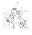
図1に示すように、本実施例の部品供給装置11(ダイ供給装置)は、マガジン保持部12(トレイタワー)、パレット引き出しテーブル13、パレット引き出し機構14、サブロボット15、シャトル機構16、反転ユニット17、突き上げユニット18(図2参照)、NGコンベア19、ノズルチェンジャー20等を備えた構成となっている。この部品供給装置11は、図3に示すように、部品実装機25のフィーダセット用スロットにパレット引き出しテーブル13を差し込んだ状態にセットされる。
DESCRIPTION OF THE PREFERRED EMBODIMENTS Hereinafter, an embodiment embodying a mode for carrying out the present invention will be described with reference to the drawings.
As shown in FIG. 1, the component supply device 11 (die supply device) of the present embodiment includes a magazine holding unit 12 (tray tower), a pallet pull-out table 13, a pallet pull-
部品供給装置11のマガジン保持部12内に上下動可能に収納されたマガジン(図示せず)には、ダイ21(ウエハ部品)を載せたウエハパレット22と、トレイ部品を載せたトレイパレット(図示せず)とを多段に混載できるようになっている。図4に示すように、ウエハパレット22は、ウエハを碁盤目状にダイシングして形成したダイ21を貼着した伸縮可能なダイシングシート36を、円形の開口部を有するウエハ装着板23にエキスパンドした状態で装着し、該ウエハ装着板23をパレット本体28にねじ止め等により取り付けた構成となっている。尚、ダイシングシート36のエキスパンドは、どのような方法で行っても良く、例えば、ダイシングシート36を下方から円形リングで押し上げた状態でウエハ装着板23に装着すれば良い。
In a magazine (not shown) housed in a
パレット引き出し機構14は、生産プログラム(生産ジョブ)に従って、ウエハパレット22とトレイパレットのいずれかのパレットをマガジン保持部12内のマガジンからパレット引き出しテーブル13上に引き出すものであり、パレット上のトレイ部品やダイ21を部品実装機25(図3参照)の吸着ノズル30a(図5、図6参照)でピックアップする位置(以下「部品実装機用引き出し位置」という)と、マガジンに近い引き出し位置(以下「サブロボット用引き出し位置」という)とのいずれの位置にもパレット22を引き出し可能に構成されている。部品実装機用引き出し位置は、パレット引き出しテーブル13の前端の位置(マガジンから最も離れた位置)であり、サブロボット用引き出し位置は、サブロボット15の吸着ノズル30b(図5、図6参照)でウエハパレット22のダイシングシート36上のダイ21を吸着可能な位置である。
The
サブロボット15は、マガジン保持部12の背面部(サブロボット用引き出し位置側の面)のうちのパレット引き出しテーブル13の上方に位置して設けられ、XZ方向(パレット引き出しテーブル13の幅方向及び上下方向)に移動するように構成されている。サブロボット15には、1本又は複数本の吸着ノズル30bが下向きに設けられ、ピックアップするダイ21のサイズ等に応じてノズルチェンジャー20で吸着ノズル30bを交換できるようになっている。サブロボット15には、カメラ24が設けられ、このカメラ24の撮像画像に基づいて、ピックアップ対象となるダイ21の位置又はダイ21の吸着姿勢を確認できるようになっている。
The
シャトル機構16は、サブロボット15の吸着ノズル30bでピックアップされた部品をシャトルノズル26で受け取って部品実装機25の吸着ノズル30aでピックアップ可能な位置まで移送する。
The
反転ユニット17は、サブロボット15から受け取るダイ21を必要に応じて上下反転させるものである。ダイ21の種類によっては、ウエハパレット22のダイシングシート36に上下反対に貼着されたダイ(例えばフリップチップ等)が存在するためである。
The
突き上げユニット18(図2参照)は、パレット引き出しテーブル13に設けられて、ウエハパレット22のダイシングシート36下方の空間領域をXY方向(パレット引き出しテーブル13の幅方向及びその直角水平方向)に移動可能に構成されている。そして、部品実装機用引き出し位置とサブロボット用引き出し位置のいずれの位置にウエハパレット22を引き出した場合でも、ダイシングシート36のうちのピックアップしようとするダイ21の貼着部分をその下方から突き上げポット27の突き上げピン29(図5、図6参照)で局所的に突き上げることで、当該ダイ21の貼着部分をダイシングシート36から部分的に剥離させてダイ21をピックアップしやすい状態に浮き上がらせるようにしている。突き上げユニット18は、ダイ21のサイズ等に応じて突き上げポット27を選択できるようにするために、複数種類(例えば4種類)の突き上げポット27が所定角度ピッチ(図2の例では90°ピッチ)で放射状に設けられ、突き上げ動作させる突き上げポット27が上向きとなる位置まで回転させるように構成されている。
The push-up unit 18 (see FIG. 2) is provided on the pallet drawer table 13 and can move in the XY direction (the width direction of the pallet drawer table 13 and the horizontal direction perpendicular thereto) in the space area below the
この突き上げユニット18は、サーボモータ(図示せず)を駆動源として突き上げユニット18全体が上下動するように構成されている。ダイピックアップ動作時には、突き上げユニット18が上昇して突き上げポット27の上面がウエハパレット22のダイシングシート36に接触する所定のシート吸着位置まで上昇すると、ストッパ機構(図示せず)によって突き上げユニット18の上昇が止まり、更に上昇動作を続けると、突き上げポット27の上面から突き上げピン29(図5、図6参照)が上方に突出して、ダイシングシート36のうちの吸着しようとするダイ21の貼着部分(吸着ノズル30a,30bの吸着点)を突き上げるようになっている。この場合、駆動源となるサーボモータの回転量を調整することで、突き上げピン29の突き上げ高さ位置を調整できるようになっている。
The push-up
尚、NGコンベア19は、不良部品や吸着不良のダイ21を排出するコンベアである。 以上のように構成した部品供給装置11の制御装置32は、図3に示すように、キーボード、マウス、タッチパネル等の入力装置33と、液晶ディスプレイ等の表示装置34等の周辺装置を備えたコンピュータにより構成され、生産プログラムに従って部品実装機25に供給する部品の種類に応じてパレットの引き出し位置と部品のピックアップ方法を選択すると共に、その選択結果に応じてパレット引き出し機構14、サブロボット15及びシャトル機構16、反転ユニット17、突き上げユニット18、部品実装機25の吸着ノズル30a等の動作を次のように制御する。
The
(1)小さいダイ21の場合
小さいダイ21の場合は、サブロボット15→シャトルノズル26→部品実装機25の吸着ノズル30aへのダイ21のつかみ替えが困難であるので、マガジン保持部12からウエハパレット22を部品実装機用引き出し位置に引き出して、当該ウエハパレット22のダイシングシート36上のダイ21を部品実装機25の吸着ノズル30aで直接ピックアップする。
(1) In the case of the
(2)上記以外のサイズのダイ21の場合
ダイ21のつかみ替えが可能なサイズのダイ21の場合は、実装時間を短縮することを目的として、マガジン保持部12内のマガジンからウエハパレット22をサブロボット用引き出し位置に引き出して、サブロボット15の吸着ノズル30bで当該ウエハパレット22のダイシングシート36上のダイ21をピックアップし、当該ダイ21をシャトル機構16のシャトルノズル26で受け取って所定のピックアップ位置まで移送し、このピックアップ位置で、シャトル機構16のシャトルノズル26からダイ21を部品実装機25の吸着ノズル30aでピックアップする。
(2) In the case of the die 21 having a size other than the above In the case of the die 21 having a size that allows the die 21 to be held, the
(3)トレイ部品の場合
トレイ部品の場合は、マガジン保持部12内のマガジンからトレイパレットを部品実装機用引き出し位置に引き出して、当該トレイパレット上の部品を部品実装機25の吸着ノズル30aで直接ピックアップする。
(3) In the case of a tray component In the case of a tray component, the tray pallet is pulled out from the magazine in the
ところで、部品実装機25の吸着ノズル30a又はサブロボット15の吸着ノズル30bでウエハパレット22のダイシングシート36上のダイ21を吸着する際に、突き上げポット27(突き上げピン29)の突き上げ高さ位置が高くなり過ぎると、吸着ノズル30a,30bの下端がダイシングシート36上のダイ21に強く当たり過ぎてダイ21が傷付いたり、割れたり、ダイ21の内部回路が損傷してしまう可能性があり、反対に、突き上げポット27(突き上げピン29)の突き上げ高さ位置が低くなり過ぎると、吸着ノズル30a,30bでダイ21を安定して吸着できない。従って、吸着ノズル30a,30bでダイ21を傷付けずに安定して吸着するためには、突き上げポット27(突き上げピン29)の突き上げ高さ位置を厳重に管理する必要がある。また、微小なダイ21を突き上げピン29で突き上げる場合は、突き上げピン29の水平方向(XY方向)の位置も厳重に管理する必要がある。
By the way, when the die 21 on the
そこで、本実施例では、突き上げユニット18の周辺に、突き上げポット27と突き上げピン29を撮像対象物とする2台のカメラ41,42を設置し、突き上げユニット18の上方にウエハパレット22をセットせずに突き上げ動作を行って、突き上げポット27を上昇させて突き上げピン29を突出させた状態で、一方のカメラ41で、突き上げポット27と突き上げピン29のX方向の側面画像を撮像し、他方のカメラ42で、突き上げポット27と突き上げピン29のY方向の側面画像を撮像するようにしている。この際、各カメラ41,42は、それぞれ視野内に突き上げポット27と突き上げピン29の両方を収めて撮像するようにしても良いし、突き上げポット27と突き上げピン29のいずれか一方を撮像した後、他方を撮像するようにしても良い。突き上げポット27と突き上げピン29とを別々に撮像する場合は、突き上げポット27については、2台のカメラ41,42のいずれか一方のみで撮像し、突き上げピン29についてのみ2台のカメラ41,42で撮像するようにしても良い。
Therefore, in this embodiment, two
また、各カメラ41,42を移動させる機構を設け、突き上げポット27と突き上げピン29を撮像するときに、各カメラ41,42を所定の撮像位置まで移動させ、それ以外の時は、各カメラ41,42をウエハパレット22等の出し入れに邪魔にならない位置に退避させるようにしても良い。突き上げポット27と突き上げピン29とを別々に撮像する場合は、各カメラ41,42を突き上げポット27の突き上げ高さ位置と突き上げピン29の突き上げ高さ位置に合わせて上下動させるようにしても良い。
In addition, a mechanism for moving the
また、撮像対象物のX方向とY方向にそれぞれプリズム又は反射鏡を配置して、プリズム又は反射鏡により所定方向に屈折又は反射された側面画像を各カメラ41,42で撮像するようにしても良い。この場合は、サブロボット15に設けられたカメラ24を用いて、突き上げポット27や突き上げピン29の側面画像を撮像するようにしても良い。
Also, prisms or reflecting mirrors may be arranged in the X direction and Y direction of the object to be imaged, and side images refracted or reflected in a predetermined direction by the prisms or reflecting mirrors may be captured by the
部品供給装置11の制御装置32は、特許請求の範囲でいう画像処理手段として機能し、生産開始前に突き上げユニット18の上方にウエハパレット22をセットせずに突き上げ動作を行って、突き上げポット27を上昇させて突き上げピン29を突出させた状態で、一方のカメラ41で、突き上げポット27と突き上げピン29のX方向の側面画像を撮像し、他方のカメラ42で、突き上げポット27と突き上げピン29のY方向の側面画像を撮像し、各カメラ41,42から出力された突き上げポット27の側面画像を画像処理して突き上げ動作時の突き上げポット27の上面の高さ位置(突き上げ高さ位置)を検出すると共に、突き上げピン29の側面画像を画像処理して突き上げ動作時の突き上げピン29の上端の高さ位置(突き上げ高さ位置)を検出する。
The
この際、各カメラ41,42の視野内に基準高さ位置を示す指標を撮像対象物と一緒に収めて撮像することで、当該基準高さ位置を基準にして突き上げポット27の上面の高さ位置や突き上げピン29の上端の高さ位置を検出するようにしても良いし、或は、各カメラ41,42の視野の高さ位置を基準にして突き上げポット27の上面の高さ位置や突き上げピン29の上端の高さ位置を検出するようにしても良い。尚、高さ位置を検出する場合は、2台のカメラ41,42の画像から求めた高さ位置を平均して最終的な高さ位置を求めるようにしても良いし、2台のカメラ41,42の片方の画像のみから高さ位置を求めるようにしても良い。
At this time, an index indicating the reference height position is stored in the field of view of each of the
部品供給装置11の制御装置32は、突き上げ動作時の突き上げポット27の上面の高さ位置や突き上げピン29の上端の高さ位置の検出結果に基づいて、それらの位置ずれ量が許容範囲を越えているか否かを判定し、それらの位置ずれ量が許容範囲を越えていると判定されれば、表示装置34等に警告表示したり、警告音を発生したりして、作業者に警告するようにしている。
Based on the detection result of the height position of the upper surface of the push-up
また、部品供給装置11の制御装置32は、突き上げピン29のX方向の側面画像とY方向の側面画像を画像処理して突き上げピン29のXY方向の位置を検出すると共に、突き上げピン29の側面画像の画像処理結果に基づいて該突き上げピン29の破損、曲りの少なくとも一方の有無を判定し、突き上げピン29の破損や曲りを検出した場合は、表示装置34等に警告表示したり、警告音を発生したりして、作業者に警告するようにしている。
In addition, the
この場合、2台のカメラ41,42を用いるため、X方向の側面画像とY方向の側面画像とを同時に撮像しても良いし、いずれか一方向の側面画像を撮像した後、他方向の側面画像を撮像するようにしても良い。
In this case, since the two
以上説明した本実施例によれば、突き上げ動作時の突き上げポット27の側面画像を画像処理して突き上げ動作時の突き上げポット27の上面の高さ位置(突き上げ高さ位置)を検出する機能を備えているため、突き上げポット27の突き上げ高さ位置を自動的に計測することができる。しかも、突き上げ動作時の突き上げピン29の側面画像を用いて、突き上げ動作時の突き上げピン29の突き上げ高さ位置を自動的に計測することができる。これにより、突き上げポット27や突き上げピン29の突き上げ高さ位置の位置ずれ量が許容範囲を越えているか否かを自動的に判定することが可能となり、突き上げポット27や突き上げピン29の突き上げ高さ位置の位置ずれを修正する作業を容易に行うことができる。
According to the present embodiment described above, a function of detecting the height position (push-up height position) of the upper surface of the push-up
しかも、本実施例では、突き上げピン29のX方向の側面画像とY方向の側面画像を画像処理して突き上げピン29のXY方向の位置を検出するようにしたので、突き上げピン29のXY方向の位置を自動的に計測することができる。これにより、突き上げピン29のXY方向の位置ずれ量が許容範囲を越えているか否かを自動的に判定することが可能となり、突き上げピン29のXY方向の位置ずれを修正する作業を容易に行うことができる。
In addition, in this embodiment, the X-direction side image and the Y-direction side image of the push-up
更に、本実施例では、突き上げピン29の側面画像の画像処理結果に基づいて該突き上げピン29の破損や曲りの有無を判定するようにしたので、突き上げピン29の破損や曲りも自動的に検出することができる。
Furthermore, in this embodiment, since the presence or absence of breakage or bending of the push-up
尚、本実施例では、突き上げポット27の突き上げ高さ位置と突き上げピン29の突き上げ高さ位置と突き上げピン29の破損・曲りを全て検出するようにしたが、これらの中から、いずれか1つ又は2つを検出するようにしても良い。
In this embodiment, the push-up height position of the push-up
また、本実施例では、2台のカメラ41,42を用いたが、1台のカメラのみとしても良い。1台のカメラで突き上げピン29のX方向の側面画像とY方向の側面画像の両方を撮像する場合は、突き上げピン29のX方向の側面画像とY方向の側面画像のいずれか一方を撮像した後、他方を撮像する位置にカメラを移動させて他方を撮像するようにすれば良い。
In this embodiment, two
また、本実施例では、部品供給装置11に設けたカメラ41,42を用いて突き上げポット27と突き上げピン29の側面画像を撮像するようにしたが、部品実装機25に設けられたカメラとプリズム等を用いて突き上げポット27と突き上げピン29の側面画像を撮像するようにしても良い。他の用途に用いられるカメラを用いて突き上げポット27や突き上げピン29の側面画像を撮像するようにすれば、カメラを増設する必要がなく、低コスト化や省スペース化の要求を満たすことができる。
In the present embodiment, the side images of the push-up
また、本実施例では、突き上げポット27と突き上げピン29の側面画像を部品供給装置11の制御装置32で画像処理するようにしたが、この画像処理を部品実装機25の制御装置で行うようにしても良い。
Further, in this embodiment, the side images of the push-up
また、本実施例では、ウエハパレット22とトレイパレットとを混載した部品供給装置11を部品実装機25にセットするようにしたが、ウエハパレット22のみを積載したダイ供給装置を部品実装機25にセットした構成に本発明を適用して実施ても良い等、本発明は種々変更して実施できる。
In this embodiment, the
11…部品供給装置(ダイ供給装置)、12…マガジン保持部、13…パレット引き出しテーブル、14…パレット引き出し機構、15…サブロボット、16…シャトル機構、17…反転ユニット、18…突き上げユニット、19…NGコンベア、20…ノズルチェンジャー、21…ダイ、22…ウエハパレット、23…ウエハ装着板、25…部品実装機、26…シャトルノズル、27…突き上げポット、28…パレット本体、29…突き上げピン、30a,30b…吸着ノズル、32…制御装置(画像処理手段)、33…入力装置、34…表示装置、36…ダイシングシート、41,42…カメラ
DESCRIPTION OF
Claims (5)
前記突き上げポットの上方に前記ウエハパレットをセットせずに突き上げ動作を行って該突き上げポットを上昇させて前記突き上げピンを突出させた状態で該突き上げピンの側面をX方向とY方向からそれぞれ撮像するカメラと、
前記カメラから出力された前記突き上げピンのX方向の側面画像とY方向の側面画像を画像処理して前記突き上げピンのXY方向の位置を検出する画像処理手段と
を備え、
前記カメラは、前記突き上げピンのX方向の側面画像を撮像するカメラと、前記突き上げピンのY方向の側面画像を撮像するカメラとが別々に設けられていることを特徴とするダイ突き上げ動作管理システム。 A wafer pallet provided with a stretchable dicing sheet to which a wafer diced so as to be divided into a plurality of dies is attached, and a push-up mechanism that moves a push-up pot disposed below the dicing sheet up and down, When the suction nozzle is lowered and the die on the dicing sheet is picked up and picked up, the push-up pot is lifted and the dicing sheet is sucked onto the upper surface of the push-up pot. Projecting upward from the upper surface of the push-up pot, the sticking portion of the die to be adsorbed in the dicing sheet is pushed up by the push-up pin, and the sticking portion of the die is partially removed from the dicing sheet. While peeling, pick up the die from the dicing sheet by sucking the die onto the suction nozzle. It applies to are backing up die supply device,
A push-up operation is performed without setting the wafer pallet above the push-up pot, and the push-up pot is lifted to project the push-up pin so that the side surfaces of the push-up pin are imaged from the X direction and the Y direction, respectively. A camera,
Image processing means for detecting the position of the push-up pin in the XY direction by performing image processing on the side image in the X direction and the side image in the Y direction of the push-up pin output from the camera ;
The die push-up operation management system , wherein the camera is provided separately with a camera for taking a side image in the X direction of the push-up pin and a camera for taking a side image in the Y direction of the push-up pin. .
前記突き上げポットの上方に前記ウエハパレットをセットせずに突き上げ動作を行って該突き上げポットを上昇させて前記突き上げピンを突出させた状態で該突き上げピンの側面をX方向とY方向からそれぞれ撮像するカメラと、
前記カメラから出力された前記突き上げピンのX方向の側面画像とY方向の側面画像を画像処理して前記突き上げピンのXY方向の位置を検出する画像処理手段と
を備え、
前記カメラは、前記突き上げピンのX方向の側面画像とY方向の側面画像のいずれか一方を撮像した後、他方を撮像する位置に移動して他方を撮像することを特徴とするダイ突き上げ動作管理システム。 A wafer pallet provided with a stretchable dicing sheet to which a wafer diced so as to be divided into a plurality of dies is attached, and a push-up mechanism that moves a push-up pot disposed below the dicing sheet up and down, When the suction nozzle is lowered and the die on the dicing sheet is picked up and picked up, the push-up pot is lifted and the dicing sheet is sucked onto the upper surface of the push-up pot. Projecting upward from the upper surface of the push-up pot, the sticking portion of the die to be adsorbed in the dicing sheet is pushed up by the push-up pin, and the sticking portion of the die is partially removed from the dicing sheet. While peeling, pick up the die from the dicing sheet by sucking the die onto the suction nozzle. It applies to are backing up die supply device,
A push-up operation is performed without setting the wafer pallet above the push-up pot, and the push-up pot is lifted to project the push-up pin so that the side surfaces of the push-up pin are imaged from the X direction and the Y direction, respectively. A camera,
Image processing means for detecting the position of the push-up pin in the XY direction by performing image processing on the side image in the X direction and the side image in the Y direction of the push-up pin output from the camera;
With
The die push-up operation management characterized in that the camera picks up one of an X-direction side image and a Y-direction side image of the push-up pin, then moves to the position where the other image is taken and picks up the other. system.
前記画像処理手段は、前記突き上げピンの側面画像の画像処理結果に基づいて該突き上げピンの破損、曲りの少なくとも一方の有無を判定する手段を備えていることを特徴とするダイ突き上げ動作管理システム。 In the die push-up operation management system according to claim 1 or 2 ,
The die push-up operation management system, wherein the image processing means includes means for determining whether or not the push pin is broken or bent based on an image processing result of a side image of the push pin.
前記カメラは、前記ダイ供給装置に設けられていることを特徴とするダイ突き上げ動作管理システム。 The die push-up operation management system according to any one of claims 1 to 3 ,
The die push-up operation management system, wherein the camera is provided in the die supply device.
前記カメラは、前記ダイ供給装置からダイが供給される部品実装機に設けられたカメラが用いられることを特徴とするダイ突き上げ動作管理システム。 The die push-up operation management system according to any one of claims 1 to 3 ,
2. The die push-up operation management system according to claim 1, wherein the camera is a camera provided in a component mounting machine to which a die is supplied from the die supply device.
Priority Applications (1)
| Application Number | Priority Date | Filing Date | Title |
|---|---|---|---|
| JP2011184278A JP5773490B2 (en) | 2011-08-26 | 2011-08-26 | Die push-up operation management system |
Applications Claiming Priority (1)
| Application Number | Priority Date | Filing Date | Title |
|---|---|---|---|
| JP2011184278A JP5773490B2 (en) | 2011-08-26 | 2011-08-26 | Die push-up operation management system |
Publications (2)
| Publication Number | Publication Date |
|---|---|
| JP2013045988A JP2013045988A (en) | 2013-03-04 |
| JP5773490B2 true JP5773490B2 (en) | 2015-09-02 |
Family
ID=48009637
Family Applications (1)
| Application Number | Title | Priority Date | Filing Date |
|---|---|---|---|
| JP2011184278A Active JP5773490B2 (en) | 2011-08-26 | 2011-08-26 | Die push-up operation management system |
Country Status (1)
| Country | Link |
|---|---|
| JP (1) | JP5773490B2 (en) |
Families Citing this family (2)
| Publication number | Priority date | Publication date | Assignee | Title |
|---|---|---|---|---|
| JP7410826B2 (en) | 2020-09-03 | 2024-01-10 | 株式会社Fuji | Pin misalignment measuring device and die feeding device |
| WO2023084647A1 (en) * | 2021-11-10 | 2023-05-19 | 株式会社Fuji | Component mounter and component mounting system |
Family Cites Families (4)
| Publication number | Priority date | Publication date | Assignee | Title |
|---|---|---|---|---|
| JPH06177182A (en) * | 1992-12-01 | 1994-06-24 | Toshiba Corp | Die bonding device and die bonding method using the device |
| JP2001196442A (en) * | 2000-01-11 | 2001-07-19 | Sony Corp | Pick-up device, method for picking up work and storage medium for storing its program |
| JP4561506B2 (en) * | 2005-07-08 | 2010-10-13 | パナソニック株式会社 | Electronic component mounting equipment |
| JP5596929B2 (en) * | 2009-02-12 | 2014-09-24 | 富士機械製造株式会社 | Method for positioning push pin and electronic component supply apparatus using the method |
-
2011
- 2011-08-26 JP JP2011184278A patent/JP5773490B2/en active Active
Also Published As
| Publication number | Publication date |
|---|---|
| JP2013045988A (en) | 2013-03-04 |
Similar Documents
| Publication | Publication Date | Title |
|---|---|---|
| JP6411028B2 (en) | Management device | |
| JP5885230B2 (en) | Die position determination system. | |
| JP5800383B2 (en) | Component mounter | |
| JP6666915B2 (en) | Component mounting machine | |
| JP2013110182A (en) | Wafer related data management method and wafer related data creation apparatus | |
| JP5777161B2 (en) | Die push-up operation management system | |
| JP2010186867A (en) | Method of positioning ejector pin and electronic component feeder using the same | |
| JP6154915B2 (en) | Component mounting equipment | |
| JP2013115229A (en) | Component mounting method and component mounting system | |
| JP5991912B2 (en) | Backup pin management device that supports the board | |
| JP5984193B2 (en) | Expanding ring inner diameter measuring system and push-up motion interference avoidance system of die feeding device | |
| JP5773490B2 (en) | Die push-up operation management system | |
| JP5988453B2 (en) | Die supply device | |
| JP6571176B2 (en) | Component mounter and component supply method for component mounter | |
| WO2014083606A1 (en) | Die supply device | |
| JP6348832B2 (en) | Component mounting apparatus, surface mounter, and component thickness detection method | |
| JP5730537B2 (en) | Die supply system | |
| EP3518646B1 (en) | Component mounter | |
| JP6470469B2 (en) | Component mounter and nozzle imaging method thereof | |
| JP6517048B2 (en) | Component mounting machine | |
| JP5627362B2 (en) | Die supply device | |
| JP5685128B2 (en) | Pallet type determination system | |
| JP6920182B2 (en) | Component mounting device | |
| JP4865917B2 (en) | Electronic component mounting device | |
| JP6739323B2 (en) | Adsorption start die teaching system |
Legal Events
| Date | Code | Title | Description |
|---|---|---|---|
| A621 | Written request for application examination |
Free format text: JAPANESE INTERMEDIATE CODE: A621 Effective date: 20140801 |
|
| A977 | Report on retrieval |
Free format text: JAPANESE INTERMEDIATE CODE: A971007 Effective date: 20150423 |
|
| A131 | Notification of reasons for refusal |
Free format text: JAPANESE INTERMEDIATE CODE: A131 Effective date: 20150507 |
|
| A521 | Request for written amendment filed |
Free format text: JAPANESE INTERMEDIATE CODE: A523 Effective date: 20150605 |
|
| TRDD | Decision of grant or rejection written | ||
| A01 | Written decision to grant a patent or to grant a registration (utility model) |
Free format text: JAPANESE INTERMEDIATE CODE: A01 Effective date: 20150626 |
|
| A61 | First payment of annual fees (during grant procedure) |
Free format text: JAPANESE INTERMEDIATE CODE: A61 Effective date: 20150626 |
|
| R150 | Certificate of patent or registration of utility model |
Ref document number: 5773490 Country of ref document: JP Free format text: JAPANESE INTERMEDIATE CODE: R150 |
|
| R250 | Receipt of annual fees |
Free format text: JAPANESE INTERMEDIATE CODE: R250 |
|
| S533 | Written request for registration of change of name |
Free format text: JAPANESE INTERMEDIATE CODE: R313533 |
|
| R350 | Written notification of registration of transfer |
Free format text: JAPANESE INTERMEDIATE CODE: R350 |
|
| R250 | Receipt of annual fees |
Free format text: JAPANESE INTERMEDIATE CODE: R250 |
|
| R250 | Receipt of annual fees |
Free format text: JAPANESE INTERMEDIATE CODE: R250 |
|
| R250 | Receipt of annual fees |
Free format text: JAPANESE INTERMEDIATE CODE: R250 |
|
| R250 | Receipt of annual fees |
Free format text: JAPANESE INTERMEDIATE CODE: R250 |
|
| R250 | Receipt of annual fees |
Free format text: JAPANESE INTERMEDIATE CODE: R250 |