JP5576868B2 - Gear cutting grinder and method for dressing grinding tools - Google Patents
Gear cutting grinder and method for dressing grinding tools Download PDFInfo
- Publication number
- JP5576868B2 JP5576868B2 JP2011525471A JP2011525471A JP5576868B2 JP 5576868 B2 JP5576868 B2 JP 5576868B2 JP 2011525471 A JP2011525471 A JP 2011525471A JP 2011525471 A JP2011525471 A JP 2011525471A JP 5576868 B2 JP5576868 B2 JP 5576868B2
- Authority
- JP
- Japan
- Prior art keywords
- axis
- linear motion
- dressing
- tool
- spindle
- Prior art date
- Legal status (The legal status is an assumption and is not a legal conclusion. Google has not performed a legal analysis and makes no representation as to the accuracy of the status listed.)
- Expired - Fee Related
Links
Images
Classifications
-
- B—PERFORMING OPERATIONS; TRANSPORTING
- B23—MACHINE TOOLS; METAL-WORKING NOT OTHERWISE PROVIDED FOR
- B23F—MAKING GEARS OR TOOTHED RACKS
- B23F23/00—Accessories or equipment combined with or arranged in, or specially designed to form part of, gear-cutting machines
- B23F23/12—Other devices, e.g. tool holders; Checking devices for controlling workpieces in machines for manufacturing gear teeth
- B23F23/1225—Arrangements of abrasive wheel dressing devices on gear-cutting machines
-
- B—PERFORMING OPERATIONS; TRANSPORTING
- B24—GRINDING; POLISHING
- B24B—MACHINES, DEVICES, OR PROCESSES FOR GRINDING OR POLISHING; DRESSING OR CONDITIONING OF ABRADING SURFACES; FEEDING OF GRINDING, POLISHING, OR LAPPING AGENTS
- B24B53/00—Devices or means for dressing or conditioning abrasive surfaces
- B24B53/06—Devices or means for dressing or conditioning abrasive surfaces of profiled abrasive wheels
Landscapes
- Engineering & Computer Science (AREA)
- Mechanical Engineering (AREA)
- Grinding-Machine Dressing And Accessory Apparatuses (AREA)
- Finish Polishing, Edge Sharpening, And Grinding By Specific Grinding Devices (AREA)
- Automatic Tool Replacement In Machine Tools (AREA)
- Gear Processing (AREA)
Abstract
Description
本発明は、第1の線形運動ユニットが、第1の線形運動軸に沿ってベッドに対して移動可能であり、第1の旋回運動ユニットを担持し、この第1の旋回運動ユニットが、前記第1の線形運動軸に対して直交である第1の旋回軸を中心として旋回し得るように第1の線形運動ユニットの上に設置され、さらに工具スピンドルが、前記第1の旋回軸に対して直交である工具スピンドル軸を中心とした回転運動として駆動され得るように第1の旋回運動ユニットの上に設置される、固定式のベッドを備える歯車研削盤に関し、さらに、本発明は、前記歯車研削盤の研削工具をドレッシングする方法に関する。 The present invention provides that the first linear motion unit is movable relative to the bed along a first linear motion axis and carries a first swivel motion unit, the first swivel motion unit being Installed on the first linear motion unit so as to be able to pivot about a first pivot axis which is orthogonal to the first linear motion axis, and a tool spindle relative to the first pivot axis A gear grinder with a fixed bed installed on the first swivel motion unit so that it can be driven as a rotational motion about a tool spindle axis that is orthogonal to each other. The present invention relates to a method for dressing a grinding tool of a gear grinding machine.
このタイプの歯車研削盤は、例えば砥石車又は研削ウォームなどの研削工具により工作物の歯車をハード仕上げする役割を果たす。この研削工具は、工作物と研磨係合するため、摩損を受ける。したがって、一定の回数の工作サイクルにわたって使用された後に、この研削工具は、ドレッシングされる必要がある。このドレッシング・プロセスにより、研削工具の所要の形状が回復し、それと同時に研削工具の表面が鋭利になる。 This type of gear grinder serves to hard finish the gears of a workpiece with a grinding tool such as a grinding wheel or grinding worm. Since this grinding tool is abrasively engaged with the workpiece, it is subject to wear. Thus, after being used over a certain number of machining cycles, the grinding tool needs to be dressed. This dressing process restores the required shape of the grinding tool while at the same time sharpening the surface of the grinding tool.
最新技術は、ドレッシング・プロセスについて、総形ドレッシング及びプロファイル・ドレッシングとして知られている2つの主要な方法を提案する。総形ドレッシングの方法においては、ドレッシング工具は、ドレッシングされることとなる研削工具の表面において制御された移動経路を辿り、それにより所望の輪郭形状の研削工具を生成する。プロファイル・ドレッシングについては、ドレッシング工具は、研削工具の所望の形成に応じて形成される。 The state of the art proposes two main methods for the dressing process known as full dressing and profile dressing. In the overall dressing method, the dressing tool follows a controlled path of movement on the surface of the grinding tool to be dressed, thereby producing a grinding tool of the desired contour shape. For profile dressing, the dressing tool is formed according to the desired formation of the grinding tool.
最新技術の歯車ホブ盤(EP0614406B1)は、ベッド上に、ベッドの長手方向に水平方向に移動可能なスタンドを備え、摺動キャリッジが、このスタンド上において垂直移動に案内される。スタンドから離れる方向に向いた摺動キャリッジの自由側には、ホブ・ウォーム歯車の支持部が、水平方向旋回軸を中心として旋回し得るように設置される。ホブ・ウォーム歯車の回転軸は、サポートの旋回軸に対して直交方向に延在する。研削工具のドレッシングの問題は、この歯車ホブ盤においては生じない。 The state-of-the-art gear hobbing machine (EP0614406B1) comprises a stand on the bed which is movable in the horizontal direction in the longitudinal direction of the bed, and the sliding carriage is guided for vertical movement on this stand. On the free side of the sliding carriage facing away from the stand, a hob / worm gear support is installed so that it can pivot about a horizontal pivot. The rotation axis of the hob / worm gear extends in a direction perpendicular to the pivot axis of the support. The grinding tool dressing problem does not occur in this gear hobbing machine.
本発明の目的は、現行において使用されている研削工具を、工具スピンドル上の定位置にロックした状態のままでドレッシングすることが可能な、本明細書の冒頭で述べた種類の歯車研削盤を提案することである。 It is an object of the present invention to provide a gear grinder of the type described at the beginning of this specification, which can dress a grinding tool currently in use while being locked in place on a tool spindle. It is to propose.
本発明によれば、解決策としての装置は、第1の線形運動ユニットの上に、第2の線形運動軸に沿って移動可能な第2の線形運動ユニットが設置され、前記第2の線形運動ユニットの上に、前記第2の線形運動軸に対して直交であるドレッシング・スピンドル軸を中心とした回転運動として駆動され得るドレッシング・スピンドルが設置されるというコンセプトにより、構成される。 According to the present invention, the apparatus as a solution is provided with a second linear motion unit movable on the first linear motion unit along the second linear motion axis, and the second linear motion unit. On the movement unit, it is constituted by the concept that a dressing spindle which can be driven as a rotational movement about a dressing spindle axis which is orthogonal to the second linear movement axis is installed.
解決策としての方法は、本発明による歯車研削盤により具現化される。この歯車研削盤のドレッシング・スピンドルは、第2の旋回運動ユニットの上に設置され、第2の旋回運動ユニットは、第2の線形運動軸に対して平行である第2の旋回運動軸を中心として旋回し得るように、第2の線形運動ユニットの上に設置され、ドレッシング工具を担持するドレッシング・スピンドルの旋回角度位置は、第2の旋回運動軸に対して固定値に設定され、前記固定値は、工具スピンドルの上に設置された研削工具に合わされ、ドレッシング工具は、所望のドレッシング方法にしたがって研削工具と係合される。 The solution method is embodied by a gear grinding machine according to the invention. The dressing spindle of this gear grinder is installed on a second swivel unit, the second swivel unit being centered on a second swivel axis that is parallel to the second linear movement axis. The swivel angle position of the dressing spindle installed on the second linear motion unit and carrying the dressing tool is set to a fixed value with respect to the second swivel motion axis, The value is matched to the grinding tool installed on the tool spindle and the dressing tool is engaged with the grinding tool according to the desired dressing method.
したがって、本発明の歯車研削盤により、及び該歯車研削盤において前述のドレッシング方法を実施することにより、例えばプロファイル・ドレッシング又は総形ドレッシングなどの各場合において望ましい特定のドレッシング方法にしたがって、例えば研削ウォーム又は砥石車などの種々のタイプの研削工具をドレッシングすることが可能となる。 Thus, according to the particular dressing method desired in each case, for example profile dressing or profile dressing, by means of the gear grinding machine according to the invention and by carrying out the above-mentioned dressing method in said gear grinding machine, for example a grinding worm Alternatively, various types of grinding tools such as grinding wheels can be dressed.
さらに、本発明による歯車研削盤の各軸の構成により、工作物に対するクランプ高さが特に低くなり、したがってシステムの剛性が高められる。 Furthermore, the configuration of each axis of the gear grinding machine according to the invention results in a particularly low clamping height with respect to the workpiece, thus increasing the rigidity of the system.
好ましくは、第1の旋回運動軸は、工具スピンドル軸と交差すべきである。この要件が厳密には満たされない場合には、制御システムにおけるソフトウェア・ベース補正により修正することが可能である。しかし、いずれの場合においても、偏差は小さくあるべきである。好ましくは、これらの2つの軸の交差は、0.1mm未満の区域内に限定されるべきである。 Preferably, the first pivot axis should intersect the tool spindle axis. If this requirement is not strictly met, it can be corrected by software-based correction in the control system. However, in any case, the deviation should be small. Preferably, the intersection of these two axes should be limited to an area of less than 0.1 mm.
第2の線形運動軸及び第2の旋回運動軸は、互いに対して可能な限り正確に位置合わせされるべきであり、工具スピンドル軸に交差すべきである。この条件が厳密には満たされない場合には、これらの軸の交差に関する許容範囲は、好ましくは5μm未満であるべきである。 The second linear motion axis and the second pivotal motion axis should be aligned as accurately as possible with respect to each other and should intersect the tool spindle axis. If this condition is not strictly met, the tolerance for crossing these axes should preferably be less than 5 μm.
好ましくは、種々の軸の間において、直交関係が必要な場合には、これは、可能な限り正確に満たされるべきである。しかし、起こり得る偏差は、それが許容範囲内にある限り、制御システムにおいてソフトウェア・ルーチンにより調整することが可能である。 Preferably, if an orthogonal relationship is required between the various axes, this should be met as accurately as possible. However, the possible deviation can be adjusted by a software routine in the control system as long as it is within an acceptable range.
本発明の目的を達成するのに適したドレッシング工具であって、ディスク形状本体を備え、このディスク形状本体が、回転軸に対して回転対称であり、2つの離間され軸方向に向く面の間に画成され、このディスク形状本体のラジアル方向において外側の周囲区域には、歯車研削盤の研削工具に作動係合する役割を果たすドレッシング領域が形成される、ドレッシング工具は、一方の軸方向に向く面のドレッシング領域が、総形ドレッシングのプロセス用に構成され、このドレッシング領域が、所望の輪郭形状の研削工具を生成するように制御された経路に沿って研削工具上を移動し、対向側の軸方向に向く面のドレッシング領域が、プロファイル・ドレッシングのプロセス用に構成され、このプロファイル・ドレッシングのプロセスについては、このドレッシング領域は、研削工具の所望の輪郭形状に応じてプロファイリングされるという特徴によって特徴付けられる。 A dressing tool suitable for achieving the object of the invention, comprising a disc-shaped body, the disc-shaped body being rotationally symmetric with respect to the axis of rotation and between two spaced apart axially oriented surfaces The dressing tool is formed in one axial direction in a radial region of the disc-shaped body in the outer peripheral area in the radial direction and serving as an operating engagement with the grinding tool of the gear grinding machine. A facing dressing area is configured for the overall dressing process, which moves over the grinding tool along a controlled path to produce a grinding tool of the desired contour, An axially facing dressing area is configured for the profile dressing process. , The dressing area is characterized by the features that are profiled according to the desired contour of the grinding tool.
「総形ドレッシング」という用語は、具体的には、プロファイル研削用の砥石車のドレッシングに該当し、「プロファイル・ドレッシング」という用語は、研削ウォームのドレッシングに該当する。 The term “total dressing” specifically corresponds to the dressing of a grinding wheel for profile grinding, and the term “profile dressing” corresponds to the dressing of a grinding worm.
本発明によるドレッシング工具においては、総形ドレッシング用に構成された前記ドレッシング領域は、その作動係合が、ドレッシングされることとなる研削工具の一点に基本的に集中し、前記ドレッシング領域が、研削工具の表面上の適切に予め定められた作動経路に沿って被制御移動を行なうことによって所望の研削工具の輪郭形状をもたらすように、輪郭形状設定される。これとは対照的に、プロファイル・ドレッシング用に構成された前記ドレッシング領域は、基本的に係合線に沿って、ドレッシングされることとなる研削工具に接触し、この場合には、研削工具の所望の輪郭形状に関する情報は、ドレッシング領域自体に包含される。この軸方向に非対称な構成により、本発明によるドレッシング工具は、ドレッシングされることとなる研削工具をこれらのドレッシング領域の一方又は他方と選択的に作動係合させることによって、総形ドレッシング及びプロファイル・ドレッシングのために使用することが可能となる。したがって、総形ドレッシングからプロファイル・ドレッシングに、又はその逆方向に切替えるために、ドレッシング工具のクランプ・デバイス内のドレッシング工具を交換する必要はない。 In the dressing tool according to the invention, the dressing area configured for a total dressing is basically concentrated in one point of the grinding tool to be dressed, the dressing area being ground. The contour shape is set to provide the desired grinding tool contour shape by performing controlled movement along a suitably predetermined actuation path on the surface of the tool. In contrast, the dressing area configured for profile dressing basically contacts the grinding tool to be dressed along the engagement line, in this case the grinding tool Information about the desired contour shape is contained in the dressing area itself. Due to this axially asymmetric configuration, the dressing tool according to the invention allows the total dressing and profile profile by selectively operatively engaging the grinding tool to be dressed with one or the other of these dressing regions. It can be used for dressing. Therefore, there is no need to change the dressing tool in the clamping device of the dressing tool in order to switch from full dressing to profile dressing or vice versa.
総形ドレッシングがドレッシング工具のドレッシング領域とドレッシングされることとなる研削工具との間における1点接触を要するということを鑑みると、実用的な一実施例においては、ドレッシング工具の軸方向断面において見た場合に、総形ドレッシング用に構成されたドレッシング領域に対して曲線形状を与えることが予期される。 In view of the fact that the overall dressing requires a single point of contact between the dressing area of the dressing tool and the grinding tool to be dressed, in a practical embodiment, it is seen in the axial section of the dressing tool. In this case, it is expected to give a curved shape to the dressing area configured for the total dressing.
他方において、プロファイル・ドレッシング用に構成されたドレッシング領域は、実用的な一実施例においては、その形状が、ドレッシング工具の軸方向断面において見た場合に、ドレッシングをドレッシングされることとなる研削工具の部分に対して与えることが意図されるプロファイル形状と形状合致するように、具現化される。ドレッシングされることとなる研削工具、具体的には研削ウォームの領域のプロファイルに対して適した断面平面を選択する際には、例えば、その軸方向断面、その法線断面、又はさらには軸方向断面及び法線断面に近い若しくはそれらの間の任意の断面平面などを考慮することが可能である。無修正インボリュートねじ面(unmodified involute screw surface)を研削するためには、ドレッシング工具の軸方向断面は、直線状に延在する。この場合には、例えば研削ウォームのプロファイル・ドレッシングにおいては、軸方向断面において見た場合の直線状ドレッシング部分は、ディスク形状本体のラジアル方向平面に対して、研削ウォームのフランク角度に対応する角度にて構成される。修正インボリュート・プロファイル(modified involute profile)に対しては、軸方向断面の形状は、それに応じて修正される。 On the other hand, a dressing area configured for profile dressing, in a practical embodiment, is a grinding tool whose dressing will be dressed when its shape is viewed in the axial section of the dressing tool. It is embodied so as to match the shape of the profile that is intended to be applied to this portion. When selecting a suitable cross-sectional plane for the profile of the grinding tool to be dressed, in particular the region of the grinding worm, for example, its axial cross-section, its normal cross-section, or even axial It is possible to consider any cross-sectional plane that is close to or between the cross-section and normal cross section. In order to grind an unmodified involute screw surface, the axial cross section of the dressing tool extends linearly. In this case, for example, in profile dressing of a grinding worm, the linear dressing portion when viewed in the axial cross section is at an angle corresponding to the flank angle of the grinding worm with respect to the radial plane of the disk-shaped body. Configured. For a modified involute profile, the shape of the axial cross section is modified accordingly.
ドレッシング工具のドレッシング領域は、特に、ドレッシング工具の本体に接合される研磨剤の層により、最新技術を用いて被覆される。この研磨層は、ポジティブ・処理又はネガティブ・処理により施すことが可能である。一般的な研磨剤には、例えば、種々の形態のコランダム、窒化ホウ素(CBN)、又はダイヤモンドが含まれる。 The dressing area of the dressing tool is coated using state-of-the-art technology, in particular with a layer of abrasive bonded to the body of the dressing tool. This polishing layer can be applied by positive treatment or negative treatment. Common abrasives include, for example, various forms of corundum, boron nitride (CBN), or diamond.
以下、図面を参照として、実用的な実施例の一例を介して本発明をさらに詳細に説明する。 Hereinafter, the present invention will be described in more detail through an example of a practical embodiment with reference to the drawings.
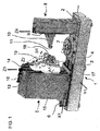
図1に図示される歯車研削盤は、歯車研削盤が設置される床平面に対して平行方向に延在する長手方向軸を有する基本的に長尺の直角平行六面体(以降においては直方体と称する。)の形状のベッド1を有し、この直方体の2つの最大表面の一方が、床平面に向く下面を形成し、対向側の表面2が、上面を形成する。上面2の上には、この直方体の長手方向軸に対して平行に延在する線形ガイド・トラック3及び4が設置され、これらの線形ガイド・トラック3及び4の上には、スタンド5が、この直方体の長手方向軸に対して平行に延在する第4の線形運動軸X1に沿って移動するように支持及び案内される。この第4の線形運動軸X1に沿ったスタンド5の移動は、制御装置から命令を受ける線形運動駆動部6によって引き起こされる。
The gear grinder illustrated in FIG. 1 is basically a long rectangular parallelepiped (hereinafter referred to as a rectangular parallelepiped) having a longitudinal axis extending in a direction parallel to the floor surface on which the gear grinder is installed. .), One of the two largest surfaces of the rectangular parallelepiped forms a lower surface facing the floor plane, and the
線形ガイド・トラック3、4は、図1において、ベッド1の約左半分にわたって延在する。図1の線形ガイド・トラック3及び4の右端部付近のベッドの上面2上には、上面2に対して直交方向に延在する工作物回転軸C1を中心とした回転移動として駆動されるように設計された回転運動ユニット7が設置される。研削されることとなる歯車の形態の工作物は、回転運動ユニット7の上にクランプ固定され、研削プロセスの要件にしたがって工作物回転軸C1を中心として制御されつつ回転される。
The linear guide tracks 3, 4 extend over approximately the left half of the bed 1 in FIG. On the
上面2に対して直交し、上面2に対して平行な断面形状がほぼ正四方形のコラム8が、図1においてはベッド1の右端部部分の上方に立設されている。コラム8は、回転運動ユニット7の方向を向く面に、上面2に対して直交方向に延在する線形ガイド・トラック9を担持する。コラム8から回転運動ユニット7の方向に突出する心押し台10は、ガイド・トラック7によって、工作物の回転軸C1に対して平行な線形摺動移動に制約される。心押し台10は、心合わせ心棒11を担持し、この心合わせ心棒11は、工作物の回転軸C1に位置合わせされ、回転運動ユニット7上にクランプ固定された工作物と心合わせされて係合する。
A column 8 which is orthogonal to the
スタンド5は、ベッド1の上面2に対して直交する4つの側壁部によって画成され、それらの側壁部の中の2つが、直方体形状のベッド1の長手方向軸に対して平行であり、他の2つが、直方体形状のベッド1の長手方向軸に対して直交する。回転運動ユニット7の方向に向く側壁部12は、上面2に対して直交方向に、及び工作物の回転軸C1に対して平行方向に延在する線形ガイド・トラック13、14を担持し、これらの線形ガイド・トラック13、14は、工作物の回転軸C1に対して平行方向に延在する第1の線形運動軸Z1に沿って、第1の線形運動ユニット15の線形移動を案内する。第1の線形運動軸Z1に沿った第1の線形運動ユニット1の移動は、制御装置から命令を受ける線形運動駆動部16によって引き起こされる。
The stand 5 is defined by four side walls perpendicular to the
第1の線形運動ユニット15の下方部分、すなわちベッド1に最も近い部分の、回転運動ユニット7の方向に向いた面には、第1の線形運動軸Z1に対して直交方向に及び直方体形状のベッド1の長手方向に対して平行方向に延在する第1の旋回運動軸A1を中心として旋回することが可能な、第1の旋回運動ユニット17が設置される。この第1の旋回運動ユニット17には、第1の旋回運動軸A1に対して直交である工具スピンドル軸B1を有する工具スピンドル18が設置される。工具スピンドル18は、制御される駆動源の動力下において、その工具スピンドル軸B1を中心として回転するように設計される。さらに、工具スピンドル18は、工具スピンドル軸B1に整列される第3の線形運動軸Y1に沿って、制御されつつ移動することが可能である。
The lower portion of the first
第1の線形運動ユニット15の上方部分、すなわちベッド1から最も遠い部分の、回転運動ユニット7の方向に向いた前面で、第2の線形運動ユニット19が、第2の線形運動軸Z2に沿った移動を制御されて案内される。第2の線形運動軸Z2は、第1の線形運動軸Z1及び第1の旋回運動軸A1に対して平行である平面内に位置する。この平面内において、第2の線形運動軸Z2は、ベッド1から離れる方向において、第1の線形運動軸Z1に対して鋭角で延在するように、第1の線形運動軸Z1に対して傾斜している。
At the upper part of the first
第2の旋回運動ユニット20が、第2の線形運動ユニット19の下方端部、すなわち工具スピンドル18の方向に向いた端部に設置される。この第2の旋回運動ユニット20は、第2の線形運動軸Z2に対して平行である第2の旋回運動軸C2を中心として旋回され得る。この第2の旋回運動ユニット20には、ドレッシング・スピンドル軸S2を中心とした回転移動にて駆動されるように設計されたドレッシング・スピンドル21が設置される。ドレッシング・スピンドル軸S2は、第2の旋回運動軸C2及び第2の線形運動軸Z2に対して直交方向に配向される。
A second
工具スピンドル18は、回転運度ユニット7上にクランプ固定された工作物の歯車歯の仕上げ動作を行なうために、歯車研削工具を保持し、その歯車研削工具に対して回転運動を与える役割を果たす。とりわけ、この仕上げ動作は、ホブ研削動作又はプロファイル研削動作からなるものであることが可能である。歯車研削工具は、例えば砥石車又は研削ウォームであることが可能である。
The
ドレッシング・スピンドル21は、総形ドレッシング及びプロファイル・ドレッシングのためのドレッシング工具を保持し、そのドレッシング工具に対して回転運動を与える役割を果たす。総形ドレッシング作動においては、ディスク形状ドレッシング工具が、ドレッシングされることとなる研削工具の表面において制御された移動経路を辿り、それにより所望の輪郭形状の研削工具を生成する。プロファイル・ドレッシングについては、ディスク形状ドレッシング工具は、研削工具の所望の輪郭形状に応じて構成される。
The dressing
それぞれ異なるドレッシング・プロセス及び工具ジオメトリに対して必要とされる、ドレッシング工具及び研削工具の互いに対する種々の配置は、各運動軸のコンピュータ制御を介して行なわれる。一実例としては、プロファイル・ドレッシングの方法のために、ドレッシング工具23を担持するドレッシング・スピンドル21の旋回角度が、第2の旋回運動軸C2に対して固定位置にクランプ固定される。さらに、ドレッシング・スピンドル軸S2を中心として回転するドレッシング・スピンドル21の1分間当たりの回転数と、工具スピンドル軸B1を中心として回転する工具スピンドル18の1分間当たりの回転数の比が、固定値に設定される。第2の線形運動軸Z2に沿った移動及び第3の線形運動軸Y1に沿った移動は、プロファイル・ドレッシング方法にしたがって制御される。総形ドレッシング方法のためには、第2の旋回運動軸C2に対するドレッシング・スピンドル21の旋回角度が、研削工具22の基準直径に応じて要求される位置に設定される。ドレッシング・スピンドル軸S2に対するドレッシング・スピンドル21の回転角度位置、及び第3の線形運動軸Y1に沿った移動は、工具スピンドル軸B1に対する工具スピンドル18の回転角度位置に応じて、総形ドレッシング方法にしたがって制御される。さらに、非旋回研削工具については、第2の線形運動軸Z2に沿った移動が制御される。
The various arrangements of the dressing tool and the grinding tool relative to each other required for different dressing processes and tool geometries are made via computer control of each motion axis. As an example, for the method of profile dressing, the turning angle of the dressing
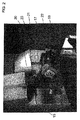
図2は、研削スピンドル18により駆動される研削工具22が研削ウォームである場合を示す。さらに、図2は、第2の旋回運動ユニット20に設置されたドレッシング・スピンドル21の上のディスク形状ドレッシング工具23を示す。
FIG. 2 shows the case where the grinding
図1の場合と同様に、図2の参照符号15は、第1の線形運動ユニットを示し、参照符号17は、第1の旋回運動ユニットを示す。
As in FIG. 1,
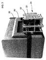
図3においては、ハウジングが定位置におかれた歯車研削盤が、図1の背面及び右手側面を見せた斜視図において示される。ハウジングの外部にその背面に隣接して配置された保持ラック24が、研削工具22、22’を、工具交換装置によるピックアップが可能な状態に保つ。これらの工具の中の1つが必要とされる場合には、その工具は、工具交換装置により、第1の線形移動軸Z1及び工作物の回転軸C1に対して直交である平面内を延在する経路に沿って、ハウジングの背面中の開口25を通り移動して、最終的には工具スピンドル18の作動スペース内に達する。工具スピンドル18は、その運動軸に対する適切に指示された運動により、工具交換装置から工具を受け、図1及び図2に示される位置において、工具スピンドル18に対してその工具をクランプ固定する。当然ながら、移動シーケンスが逆転する場合には、工具スピンドル18上にクランプ固定された、交換される必要のある工具が、工具交換機により受け取られ、外部に搬送され、保持フレーム24内に配置される。工具の交換が行なわれていないときには、ハウジング中の開口25は、摺動ドア26により閉じられる。
In FIG. 3, the gear grinding machine with the housing in place is shown in a perspective view showing the back and right hand sides of FIG. A holding
背面とは逆方向に向いており、したがってこの図においては見ることのできないハウジングの正面は、水平方向摺動ドアを備え、このドアは、開位置においては、歯車研削盤の作業スペース、すなわちスタンド5とコラム8との間のスペースへのアクセスを可能にし、閉位置においては、外部に対して歯研削盤を完全に遮蔽する。 The front of the housing, which faces away from the back and is therefore not visible in this figure, is provided with a horizontal sliding door, which in the open position is the working space of the gear grinding machine, ie the stand. Access to the space between 5 and column 8 is possible, and in the closed position the tooth grinder is completely shielded from the outside.
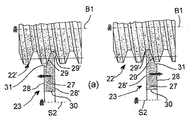
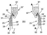
図4(a)及び図4(b)はそれぞれ、工具スピンドル軸B1及びドレッシング・スピンドル軸S2を含む断面平面において描いた、進行中のドレッシング動作を示す。歯車研削工具22は、図4(a)においてはホブ研削ウォーム22’であり、図4(b)においては砥石車22’’である。ドレッシング工具23は、両方の場合において同一である。
FIGS. 4 (a) and 4 (b) show the ongoing dressing operation, drawn in a cross-sectional plane including the tool spindle axis B1 and the dressing spindle axis S2, respectively. The
詳細な特徴に関して述べると、このドレッシング工具23は、ドレッシング・スピンドル軸S2に対して回転対称であるディスク形状本体27を有し、図4(a)及び図4(b)においては、ドレッシング・スピンドル軸S2の上方に延在する本体27の半分のみが示される。このディスク形状本体は、互いからある軸方向距離で離間された2つの軸方向に向く面28、28’の間に画成される。これらの軸方向に向く面28、28’のラジアル方向における外側の周囲区域が、それぞれドレッシング領域29及び29’として構成される。これらのドレッシング領域29及び29’のそれぞれにおいて、ドレッシング工具の本体27は、本体27に接合された研削剤で被覆される。本体27のラジアル方向において中央の区域には、ハブ30が形成される。このハブ30は、ドレッシング・スピンドル軸S2と同軸であり、本体27をドレッシング・スピンドル21に対してクランプ固定するのを可能にする。
In more detail, the dressing
図4(a)及び図4(b)に図示される軸方向断面においては、プロファイル・ドレッシングのために構成されたドレッシング領域29が、本体27のラジアル方向鞍部31から始まり、対向側の軸方向に向く面28’に対してある角度にてラジアル方向に外方に延在し、本体27のラジアル方向外方端部32にて終端する。ドレッシングされることとなる研削工具が、無修正インボリュートねじ面を研削するように設計される場合には、この輪郭形状は、直線を辿り、修正ねじ面(modified screw surface)の場合には、それに応じて適切に構成される。これとは対照的に、総形ドレッシング用に構成されたドレッシング領域29’の軸方向断面輪郭形状は、初めに軸方向に向く面28’から外方に曲線弧状に突出し、次に外方端部32の方向に弧状曲線にて曲がって戻る。
4 (a) and 4 (b), the
図4(a)は、プロファイル・ドレッシング・プロセスの際の、ドレッシング工具23とホブ研削ウォーム22’との間の作動係合を示す。図4(a)の左側の図においては、ドレッシング領域29は、線形接触区域に沿ってホブ研削ウォーム22’の左フランクと作動係合状態にある。送り運動は、矢印によって示されるように、左フランクに対して軸方向に行なわれる。図4(a)の右側の図においては、ホブ研削ウォーム22’の右フランクに対するプロファイル・ドレッシング・プロセスが図示される。この場合には、ドレッシング工具23の配向及び送り運動は、図4(a)の左側の図のものと鏡像対称になる。これらの両方の場合において、総形ドレッシング用に構成されたドレッシング領域29’は、ホブ研削ウォーム22’のフランクから離れた位置に留まり、したがってドレッシング・プロセス全体にわたって非作動状態にある。
FIG. 4 (a) shows the operative engagement between the dressing
それとは対照的に、図4(b)は、砥石車22’’の総形ドレッシングを図示し、この場合には、プロファイル・ドレッシングのために設計されたドレッシング領域29は、非係合状態に、したがって非作動状態にあり、総形ドレッシング領域29’は、基本的に一点に集中される作動係合により、砥石車22’の左側(図4(b)の左側図において)と、及び右側(図4(b)の右側図において)と接触状態になり、総形ドレッシング領域29’は、所望の輪郭形状を生成する経路に沿って、砥石車22’の側部上を案内される。図面の平面内に位置するこの移動経路の成分は、図4(b)の左側図及び右側図の双方の中の矢印によって示される。
In contrast, FIG. 4 (b) illustrates the overall dressing of the
1 ベッド
2 上面
3、4 線形ガイド・トラック
5 スタンド
6 線形運動駆動部
7 回転運動ユニット
8 コラム
9 線形ガイド・トラック
10 心押し台
C1 工作物の回転軸
11 心合わせ心棒
12 側壁部
13、14 線形ガイド・トラック
15 第1の線形運動ユニット
16 線形運動駆動部
17 第1の旋回運動ユニット
A1 第1の旋回運動軸
18 工具スピンドル
B1 工具スピンドル軸
Y1 第3の線形運動軸
19 第2の線形運動ユニット
Z2 第2の線形運動軸
20 第2の旋回運動ユニット
C2 第2の旋回運動軸
21 ドレッシング・スピンドル
S2 ドレッシング・スピンドル軸
22 研削工具
22’ ホブ研削ウォーム
22’’ 砥石車
23 ドレッシング工具
24 保持フレーム
25 ハウジングの開口
26 摺動ドア
27 ディスク形状本体
28、28’ 軸方向に向く面
29、29’ ドレッシング領域
30 ハブ
31 ラジアル方向鞍部
32 外方端部
DESCRIPTION OF SYMBOLS 1
Claims (15)
Applications Claiming Priority (3)
| Application Number | Priority Date | Filing Date | Title |
|---|---|---|---|
| EP08015643A EP2161092B1 (en) | 2008-09-04 | 2008-09-04 | Gear grinder and method for dressing a grinding tool |
| EP08015643.3 | 2008-09-04 | ||
| PCT/EP2009/006453 WO2010025942A2 (en) | 2008-09-04 | 2009-09-04 | Gear cutting grinding machine and method for dressing a grinding tool |
Publications (2)
| Publication Number | Publication Date |
|---|---|
| JP2012501859A JP2012501859A (en) | 2012-01-26 |
| JP5576868B2 true JP5576868B2 (en) | 2014-08-20 |
Family
ID=40561823
Family Applications (1)
| Application Number | Title | Priority Date | Filing Date |
|---|---|---|---|
| JP2011525471A Expired - Fee Related JP5576868B2 (en) | 2008-09-04 | 2009-09-04 | Gear cutting grinder and method for dressing grinding tools |
Country Status (8)
| Country | Link |
|---|---|
| US (1) | US8882564B2 (en) |
| EP (2) | EP2161092B1 (en) |
| JP (1) | JP5576868B2 (en) |
| CN (2) | CN103144042B (en) |
| AT (1) | ATE553871T1 (en) |
| ES (1) | ES2404828T3 (en) |
| PL (1) | PL2326449T3 (en) |
| WO (1) | WO2010025942A2 (en) |
Families Citing this family (33)
| Publication number | Priority date | Publication date | Assignee | Title |
|---|---|---|---|---|
| CN101961801B (en) * | 2010-09-02 | 2013-07-24 | 王延忠 | Hobbing equipment for face gear |
| DE102010049319A1 (en) * | 2010-10-22 | 2012-04-26 | Gleason-Pfauter Maschinenfabrik Gmbh | Führunsanordnung and machine tool with such a guide assembly |
| DE102011103216A1 (en) * | 2011-06-01 | 2012-12-06 | Liebherr-Verzahntechnik Gmbh | Method of dressing a tool |
| TWI480113B (en) * | 2011-10-07 | 2015-04-11 | Nat Univ Chung Cheng | Variable tooth thickness worm type tool and processing method thereof |
| DE102011120449A1 (en) | 2011-12-07 | 2013-06-13 | Gleason-Pfauter Maschinenfabrik Gmbh | Method for grinding toothed workpieces and apparatus designed for this purpose |
| DE102012017840B3 (en) * | 2012-09-08 | 2013-12-12 | Klingelnberg Gmbh | Gear grinding machine makes angle between straight line of axis of rotation of straightening roller and vector of straightening direction of straightening roller |
| DE102013001797A1 (en) * | 2013-02-01 | 2014-08-07 | Liebherr-Verzahntechnik Gmbh | Gear grinding machine e.g. profile-grinding machine has straightening spindle mounted on driving stand, whose pivot axis is rotatably mounted about axis perpendicular to pivot axis of grinding spindle |
| JP5536250B1 (en) * | 2013-03-22 | 2014-07-02 | 三菱重工業株式会社 | Gear processing equipment |
| CN103317443A (en) * | 2013-06-14 | 2013-09-25 | 西安共达精密机器有限公司 | Offline grinding wheel dresser and dressing method |
| ITBO20130381A1 (en) * | 2013-07-19 | 2015-01-20 | Samp Spa Con Unico Socio | METHOD, TOOL AND DEVICE FOR THE PROFILING OF A FINISHING TOOL |
| DE102013013276A1 (en) * | 2013-08-08 | 2015-02-12 | Liebherr-Verzahntechnik Gmbh | Machine tool and method for machining workpieces with at least two separate machining units |
| CN104801783A (en) * | 2014-01-24 | 2015-07-29 | 陆联精密股份有限公司 | Gear grinding equipment |
| JP5774740B2 (en) * | 2014-02-28 | 2015-09-09 | 陸聯精密股▲ふん▼有限公司 | Gear grinding machine with tool modification function |
| US20150266121A1 (en) * | 2014-03-19 | 2015-09-24 | Luren Precision Co., Ltd. | Gear grinding apparatus providing tool modification function |
| CH709478A1 (en) * | 2014-04-08 | 2015-10-15 | Reishauer Ag | Methods and apparatus for fast and flexible dressing of the grinding worm. |
| CN104475874B (en) * | 2014-12-16 | 2016-08-10 | 中北大学 | The ultrasonic accurate hobbing device of a kind of gear and application |
| DE102015100374A1 (en) * | 2015-01-13 | 2016-07-14 | Klingelnberg Ag | Method for compensating for temperature variations in a grinding machine and correspondingly equipped grinding machine |
| DE102015000908A1 (en) * | 2015-01-23 | 2016-07-28 | Liebherr-Verzahntechnik Gmbh | Method and device for gear processing a workpiece by a diagonal rolling process |
| DE102015009287A1 (en) * | 2015-07-10 | 2017-01-12 | Liebherr-Verzahntechnik Gmbh | Method for producing a workpiece with a desired tooth geometry |
| DE102015008972A1 (en) * | 2015-07-10 | 2017-01-12 | Liebherr-Verzahntechnik Gmbh | Method for producing one or more workpieces |
| CN105478922B (en) * | 2016-01-28 | 2017-08-29 | 中北大学 | A kind of ultrasonic scraping devices and its application |
| DE102016004112A1 (en) * | 2016-04-05 | 2017-10-05 | Gleason-Pfauter Maschinenfabrik Gmbh | METHOD FOR PRODUCING A DEPOSITION ON A TOOTHED EDGE AND DEVICE DESIGNATED THEREFOR |
| CN107414205A (en) * | 2016-12-09 | 2017-12-01 | 盐城秦川华兴机床有限公司 | Interior helical teeth gear grinding machines |
| EP3348354B1 (en) | 2017-01-16 | 2020-01-08 | Klingelnberg AG | Method for processing bevel gears using an eccentrically moved, dressable cup grinding disc |
| DE102017011978A1 (en) * | 2017-12-22 | 2019-06-27 | Gleason-Pfauter Maschinenfabrik Gmbh | Method for machining toothings and gear cutting machine |
| JP6653338B2 (en) * | 2018-01-31 | 2020-02-26 | 三菱重工工作機械株式会社 | Gear grinding equipment |
| EP3698919B1 (en) * | 2019-02-20 | 2024-05-08 | Klingelnberg AG | Method for dressing a grinding tool |
| CN113996872B (en) * | 2020-07-28 | 2024-03-15 | 湖南飞阳齿轮制造有限责任公司 | Gear grinding machine for gear machining and gear grinding method thereof |
| CN113123627B (en) * | 2021-03-05 | 2023-04-28 | 东莞生态园混凝土有限公司 | Auxiliary construction device for reinforcing cross beam by using carbon fiber cloth |
| CN113070779A (en) * | 2021-04-15 | 2021-07-06 | 潍坊利金机械设备有限公司 | A equipment that is used for check valve core to polish processing |
| CN113210551B (en) * | 2021-05-26 | 2024-08-23 | 洛阳科大越格数控机床有限公司 | A rolling processing method for face gear |
| CN119609941A (en) * | 2024-12-09 | 2025-03-14 | 西安奕斯伟材料科技股份有限公司 | Polishing pad dressing device, method and control device |
| CN121607717A (en) * | 2026-02-03 | 2026-03-06 | 湖南理工职业技术学院 | High-precision machining method for complex curved gear |
Family Cites Families (28)
| Publication number | Priority date | Publication date | Assignee | Title |
|---|---|---|---|---|
| US440916A (en) | 1890-11-18 | Bottle-filling machine | ||
| SU880244A3 (en) * | 1978-08-18 | 1981-11-07 | Мааг-Цанрэдер Унд-Машинен Аг (Фирма) | Method and lathe for grinding gear wheels |
| CH639305A5 (en) * | 1979-06-20 | 1983-11-15 | Maag Zahnraeder & Maschinen Ag | PARTIAL ROLLING METHOD AND DEVICE FOR GRINDING GEARS WITH EVOLVENT-SHAPED TOOTH-FLANGE PROFILE. |
| DE3320042A1 (en) * | 1983-06-03 | 1984-12-13 | Dieter Dr.-Ing. 7505 Ettlingen Wiener | METHOD FOR GRINDING PRE-GEARED AND GRINDING MACHINE FOR CARRYING OUT THIS METHOD |
| JPH0639859Y2 (en) * | 1986-07-02 | 1994-10-19 | 株式会社カシフジ | Hob changer for hobbing machine |
| DE3941439A1 (en) * | 1989-12-15 | 1991-06-20 | Buderus Schleiftechnik | METHOD AND DEVICE FOR GRINDING AN INTERNAL THREAD |
| US5228814A (en) | 1991-11-25 | 1993-07-20 | The Gleason Works | Gear hobbing machine |
| DE4210710C2 (en) * | 1992-03-27 | 2003-03-20 | Niles Werkzeugmaschinen Gmbh | Method and device for grinding groove-shaped outer profiles of a workpiece |
| DE19619401C1 (en) * | 1996-05-14 | 1997-11-27 | Reishauer Ag | Method and appliance for profiling grinding worms |
| DE19624842C2 (en) * | 1996-06-21 | 2000-08-10 | Reishauer Ag | Method for the flexible profiling of grinding worms, a profiling tool and a device for carrying out the method |
| DE19625370C1 (en) * | 1996-06-25 | 1997-04-30 | Reishauer Ag | Grinding machine for continuous roller grinding of spur wheel gears |
| DE29717193U1 (en) | 1997-09-25 | 1997-11-20 | Oerlikon Geartec AG, Zürich | Internal grinding head with dressable grinding wheel |
| DE19827897A1 (en) * | 1998-06-23 | 1999-12-30 | Oerlikon Geartec Ag Zuerich | Procedure for grinding at least one surface on cutting blade used in machining |
| DE19910747B9 (en) * | 1999-03-11 | 2012-03-08 | Reishauer Ag | Method and device for centering a dressing tool in the gear gap of a grinding worm |
| DE10344945B4 (en) * | 2003-09-27 | 2006-02-16 | The Gleason Works | Method for part-generating grinding of the tooth flanks and additionally grinding the tooth tips of toothed workpieces, in particular Schabrädern in a clamping with a disc-shaped grinding wheel |
| JP4220944B2 (en) * | 2004-07-15 | 2009-02-04 | 三菱重工業株式会社 | Gear grinding machine |
| JP2006035340A (en) * | 2004-07-23 | 2006-02-09 | Mitsubishi Heavy Ind Ltd | Gear grinding device and gear grinding method |
| JP4202306B2 (en) * | 2004-07-29 | 2008-12-24 | 三菱重工業株式会社 | Gear grinding machine |
| CA2581724C (en) * | 2005-02-03 | 2010-11-30 | David J. Fisher | Method and apparatus for manufacturing a face gear |
| CN2788947Y (en) * | 2005-06-03 | 2006-06-21 | 河南科技大学 | Internal gear forming gear grinding machine tool |
| US8267624B2 (en) * | 2005-06-27 | 2012-09-18 | The Gleason Works | Full point width cutting blades |
| CN100507316C (en) * | 2005-12-30 | 2009-07-01 | 武汉理工大学 | Point line meshed gear and its tooth grinding method |
| JP4648219B2 (en) * | 2006-02-28 | 2011-03-09 | 三菱重工業株式会社 | Gear grinding machine |
| DE102007020479B4 (en) * | 2007-04-27 | 2010-10-21 | Kapp Gmbh | Method and grinding machine for profiling a grinding tool |
| DE102008010302A1 (en) * | 2008-02-21 | 2009-08-27 | Liebherr-Verzahntechnik Gmbh | Device and method for prototype and small batch production of gears |
| DE102008010301A1 (en) * | 2008-02-21 | 2009-09-03 | Liebherr-Verzahntechnik Gmbh | Method for operating a gear grinding machine |
| DE102009023275A1 (en) * | 2009-05-29 | 2010-12-02 | Liebherr-Verzahntechnik Gmbh | gear cutting |
| WO2011043225A1 (en) * | 2009-10-05 | 2011-04-14 | 本田技研工業株式会社 | Device and method for measuring tooth surface run-out, device and method for moulding grinding tool, and method for aligning teeth in a gear wheel grinding device |
-
2008
- 2008-09-04 EP EP08015643A patent/EP2161092B1/en not_active Not-in-force
- 2008-09-04 AT AT08015643T patent/ATE553871T1/en active
-
2009
- 2009-09-04 US US13/061,258 patent/US8882564B2/en not_active Expired - Fee Related
- 2009-09-04 WO PCT/EP2009/006453 patent/WO2010025942A2/en not_active Ceased
- 2009-09-04 JP JP2011525471A patent/JP5576868B2/en not_active Expired - Fee Related
- 2009-09-04 CN CN201310021602.0A patent/CN103144042B/en not_active Expired - Fee Related
- 2009-09-04 EP EP09778350.0A patent/EP2326449B9/en active Active
- 2009-09-04 CN CN2009801350014A patent/CN102143820B/en not_active Expired - Fee Related
- 2009-09-04 ES ES09778350T patent/ES2404828T3/en active Active
- 2009-09-04 PL PL09778350T patent/PL2326449T3/en unknown
Also Published As
| Publication number | Publication date |
|---|---|
| CN103144042A (en) | 2013-06-12 |
| EP2161092B1 (en) | 2012-04-18 |
| PL2326449T3 (en) | 2013-08-30 |
| EP2326449B9 (en) | 2013-12-25 |
| WO2010025942A2 (en) | 2010-03-11 |
| CN102143820B (en) | 2013-11-06 |
| ES2404828T9 (en) | 2014-02-03 |
| EP2326449B1 (en) | 2013-03-13 |
| CN102143820A (en) | 2011-08-03 |
| CN103144042B (en) | 2016-02-10 |
| US20110159787A1 (en) | 2011-06-30 |
| ES2404828T3 (en) | 2013-05-29 |
| EP2161092A1 (en) | 2010-03-10 |
| US8882564B2 (en) | 2014-11-11 |
| JP2012501859A (en) | 2012-01-26 |
| EP2326449A2 (en) | 2011-06-01 |
| ATE553871T1 (en) | 2012-05-15 |
| WO2010025942A3 (en) | 2010-11-25 |
Similar Documents
| Publication | Publication Date | Title |
|---|---|---|
| JP5576868B2 (en) | Gear cutting grinder and method for dressing grinding tools | |
| JP4648219B2 (en) | Gear grinding machine | |
| CN102264510B (en) | Internal gear grinding machine and dressing method for barrel thread cutters | |
| JP4220944B2 (en) | Gear grinding machine | |
| JP5857660B2 (en) | Grinding machine truing device | |
| JP4202306B2 (en) | Gear grinding machine | |
| CN102806523B (en) | The method of dressing tool and gear lapping machine | |
| JP5244577B2 (en) | Internal gear grinding machine | |
| JP2008279594A (en) | Precision machining apparatus for precision finishing of workpiece | |
| JP2009255186A (en) | Grinder and grinding method | |
| RU2009120199A (en) | METHOD AND GRINDING MACHINE FOR COMPLETE GRINDING OF SHORT AND / OR STEREOF-PROCESSED PARTS (OPTIONS) | |
| JPH1058230A (en) | Method and device for precision machining of flat gear | |
| TWI381905B (en) | Three-track grinding machine | |
| US9011208B2 (en) | Dual-spindle grinder | |
| JP5703761B2 (en) | Truing method for grinding machine and grinding wheel | |
| JP5475343B2 (en) | Rotary saw grinding equipment | |
| JP5125391B2 (en) | Swivel device and cylindrical grinder provided with the same | |
| JP2016083707A (en) | Nc grinder processing device having dressing grindstone mounted thereon | |
| JP6197567B2 (en) | Truing method and truing device | |
| JPS61146471A (en) | Dressing device | |
| JP4365751B2 (en) | Gear grinding machine | |
| JP5549391B2 (en) | Grinder | |
| JP2010179444A (en) | Grinding machine and grinding method | |
| CN101249621A (en) | Numerical control grinding method of axis series workpiece | |
| JP2003103462A (en) | Truing device in grinder having two wheel spindle stocks |
Legal Events
| Date | Code | Title | Description |
|---|---|---|---|
| A621 | Written request for application examination |
Free format text: JAPANESE INTERMEDIATE CODE: A621 Effective date: 20120619 |
|
| A977 | Report on retrieval |
Free format text: JAPANESE INTERMEDIATE CODE: A971007 Effective date: 20130912 |
|
| A131 | Notification of reasons for refusal |
Free format text: JAPANESE INTERMEDIATE CODE: A131 Effective date: 20130920 |
|
| A601 | Written request for extension of time |
Free format text: JAPANESE INTERMEDIATE CODE: A601 Effective date: 20131220 |
|
| A602 | Written permission of extension of time |
Free format text: JAPANESE INTERMEDIATE CODE: A602 Effective date: 20140106 |
|
| A521 | Request for written amendment filed |
Free format text: JAPANESE INTERMEDIATE CODE: A523 Effective date: 20140120 |
|
| TRDD | Decision of grant or rejection written | ||
| A01 | Written decision to grant a patent or to grant a registration (utility model) |
Free format text: JAPANESE INTERMEDIATE CODE: A01 Effective date: 20140624 |
|
| A61 | First payment of annual fees (during grant procedure) |
Free format text: JAPANESE INTERMEDIATE CODE: A61 Effective date: 20140704 |
|
| R150 | Certificate of patent or registration of utility model |
Ref document number: 5576868 Country of ref document: JP Free format text: JAPANESE INTERMEDIATE CODE: R150 |
|
| R250 | Receipt of annual fees |
Free format text: JAPANESE INTERMEDIATE CODE: R250 |
|
| R250 | Receipt of annual fees |
Free format text: JAPANESE INTERMEDIATE CODE: R250 |
|
| R250 | Receipt of annual fees |
Free format text: JAPANESE INTERMEDIATE CODE: R250 |
|
| R250 | Receipt of annual fees |
Free format text: JAPANESE INTERMEDIATE CODE: R250 |
|
| R250 | Receipt of annual fees |
Free format text: JAPANESE INTERMEDIATE CODE: R250 |
|
| LAPS | Cancellation because of no payment of annual fees |