JP5552609B2 - Game machine - Google Patents
Game machine Download PDFInfo
- Publication number
- JP5552609B2 JP5552609B2 JP2008052083A JP2008052083A JP5552609B2 JP 5552609 B2 JP5552609 B2 JP 5552609B2 JP 2008052083 A JP2008052083 A JP 2008052083A JP 2008052083 A JP2008052083 A JP 2008052083A JP 5552609 B2 JP5552609 B2 JP 5552609B2
- Authority
- JP
- Japan
- Prior art keywords
- control circuit
- program
- game control
- game
- fraud
- Prior art date
- Legal status (The legal status is an assumption and is not a legal conclusion. Google has not performed a legal analysis and makes no representation as to the accuracy of the status listed.)
- Active
Links
Images


Description
本発明は、遊技機の技術分野に属する。 The present invention belongs to the technical field of gaming machines.
遊技の進行を制御するための遊技制御プログラムを搭載した遊技機(パチンコ機や回胴式遊技機)は、搭載している遊技制御プログラムが遊技規則上の要件を具備するか否かが検査され、その検査に合格した遊技機のみが製造と販売を許されている。
一方、近年、これらの遊技機に対する不正な改造その他の変更が巧妙、複雑になってきている。これらの不正を防止してパチンコホールの健全化を図るためには、不正改造等を検知しホールコンピュータ等に報知する必要がある。 On the other hand, in recent years, unauthorized modification and other changes to these gaming machines have become more sophisticated and complicated. In order to prevent these irregularities and to make the pachinko hall sound, it is necessary to detect unauthorized modifications and notify the hall computer or the like.
ところが、不正行為を防止するための不正防止プログラムを上述した遊技の進行を制御するための遊技制御プログラムと同一に捉えると、プログラム容量が増加する結果、検査機関における上述の検査及び社内におけるチェックに時間がかかるという課題、容量が多いのでプログラムの作成時又は検査時にミスを誘発するという課題、容量が多いのでプログラムの改竄等の温床になり易いという課題等が考えられた。 However, if the anti-fraud program for preventing fraud is considered the same as the above-described game control program for controlling the progress of the game, the program capacity increases. The problem of taking time, the problem of inducing mistakes at the time of program creation or inspection due to the large capacity, and the problem of being likely to become a hotbed such as program tampering due to the large capacity were considered.
上述の課題は、遊技の進行を制御するための遊技制御プログラムを搭載した主制御回路(遊技制御回路)のみならず、景品体(賞球やメダル等)の払出制御を行う払出制御プログラムを搭載した払出制御回路についても同様である。 The above-mentioned issues include not only a main control circuit (game control circuit) equipped with a game control program for controlling the progress of the game, but also a payout control program for payout control of prizes (prize balls, medals, etc.). The same applies to the payout control circuit.
第1の発明に係る遊技機は、
遊技の進行を制御するための遊技制御プログラムを記憶した遊技制御領域と、不正行為を防止するための不正防止用プログラムを記憶した不正防止制御領域とを分離したROMと、
該ROMと、該ROMに記憶されている前記遊技制御プログラム及び前記不正防止用プログラムを実行するCPUと、前記CPUがアクセスするRAMとを備える遊技制御回路を有し、
該RAMは、前記遊技制御プログラムの作業領域と、前記不正防止用プログラムの作業領域とが分離されることを特徴とする。
The gaming machine according to the first invention is
A ROM that separates a game control area that stores a game control program for controlling the progress of the game and a fraud prevention control area that stores a fraud prevention program for preventing fraud;
A game control circuit including the ROM, a CPU that executes the game control program and the anti-fraud program stored in the ROM, and a RAM that is accessed by the CPU;
The RAM is characterized in that a work area of the game control program and a work area of the fraud prevention program are separated.
第1の発明に係る遊技機に備わるROMは、遊技制御領域(遊技制御プログラム)と不正防止制御領域(不正防止用プログラム)とを分離したので、遊技制御プログラムと不正防止用プログラムの区別が容易であり、遊技制御プログラムの検査、チェックが簡単である。この結果、プログラム作成ミスの発生、プログラムの改竄を未然に防止する効果が期待できる。また、不正防止用プログラムが改竄されても遊技の性能には直接関係しないので、この点でも耐性が高い。
また、RAMは、遊技制御プログラムの作業領域と、不正防止用プログラムの作業領域とが分離される構成であるから、RAMの作業領域においても遊技制御プログラムと不正防止用プログラムの区別が明瞭である。
Since the ROM provided in the gaming machine according to the first aspect of the invention separates the game control area (game control program) and the anti-fraud control area (program for fraud prevention), it is easy to distinguish the game control program from the anti-fraud program. It is easy to check and check the game control program. As a result, it can be expected to prevent the occurrence of a program creation error and the alteration of the program. Further, even if the fraud prevention program is tampered with, it is not directly related to the performance of the game.
In addition, since the RAM has a configuration in which the work area of the game control program and the work area of the fraud prevention program are separated, the distinction between the game control program and the fraud prevention program is clear even in the RAM work area. .
第2の発明に係る遊技機は、前記RAMでは、前記遊技制御プログラムの作業領域を予め設定されたアドレス空間(以下、「エリア1」という)内に収め、前記不正防止用プログラムの作業領域を前記エリア1外にすることを特徴とする第1の発明に係る遊技機であり、遊技制御プログラムの作業領域と不正防止用プログラムの作業領域とを分離するための一構成例である。
In the gaming machine according to the second aspect of the present invention, in the RAM, the work area of the game control program is stored in a preset address space (hereinafter referred to as “
請求項1記載の遊技機は、
遊技の進行を制御する遊技制御回路と、
賞球に係る制御をするための賞球制御プログラムを記憶した賞球制御領域と、不正行為を防止するための賞球不正防止用プログラムを記憶した賞球不正防止制御領域とを分離したROMと、該ROMに記憶されている前記賞球制御プログラム及び前記賞球不正防止用プログラムを実行するCPUと、前記CPUがアクセスするRAMとを備える賞球制御回路と、を有し、
該RAMは、前記賞球制御プログラムの作業領域と、前記不正防止用プログラムの作業領域とが分離されることを特徴とする遊技機であって、
前記賞球制御回路には、当該遊技機に外部から及ぼされる磁力を検出するための磁気センサと、前面枠が開放されたことを検出する扉開放スイッチと、当該遊技機が振動させられたことを検出する振動センサとのうちの少なくとも一つを接続し、
前記遊技制御回路には、発射制御回路が接続されていると共に、遊技の進行を制御するための遊技制御プログラムを記憶した遊技制御領域と、不正行為を防止するための遊技不正防止用プログラムを記憶した遊技不正防止制御領域とを分離したROMと、該ROMに記憶されている前記遊技制御プログラム及び前記遊技不正防止用プログラムを実行するCPUと、前記CPUがアクセスし、前記遊技制御プログラムの作業領域と、前記遊技不正防止用プログラムの作業領域とが分離されるRAMと、を備え、
前記賞球制御回路は、前記磁気センサ、前記扉開放スイッチ、または、前記振動センサの検出信号が検出レベルであれば、その旨を示す不正検出信号を前記遊技制御回路へ送信し、
前記遊技制御回路は、前記不正検出信号を受信すると、前記RAMにおける前記遊技制御プログラムの作業領域に不正フラグをセットし、
前記遊技制御回路は、前記不正フラグがセットされていれば、発射の停止を指示するための信号を前記発射制御回路に出力すること、を特徴とする。
The gaming machine according to
A game control circuit for controlling the progress of the game;
A prize balls control region which stores prize balls control program for the control of the prize balls, a ROM that separate the winning balls fraud control region which stores winning balls fraud prevention program for preventing abuse A prize ball control circuit comprising: a CPU for executing the prize ball control program and the prize ball fraud prevention program stored in the ROM; and a RAM accessed by the CPU;
The RAM is a gaming machine in which a work area of the prize ball control program and a work area of the fraud prevention program are separated,
The prize ball control circuit includes a magnetic sensor for detecting a magnetic force exerted on the gaming machine from the outside, a door opening switch for detecting that the front frame is opened, and the gaming machine is vibrated. Connecting at least one of the vibration sensor and
The game control circuit is connected to a launch control circuit and stores a game control area storing a game control program for controlling the progress of the game and a game fraud prevention program for preventing fraud A ROM that is separated from the gaming fraud prevention control area, a CPU that executes the game control program and the game fraud prevention program stored in the ROM, and a work area of the game control program that is accessed by the CPU And a RAM for separating a work area of the gaming fraud prevention program,
If the detection signal of the magnetic sensor, the door opening switch, or the vibration sensor is a detection level, the prize ball control circuit transmits a fraud detection signal indicating that to the game control circuit,
When the game control circuit receives the fraud detection signal, the game control circuit sets a fraud flag in a work area of the game control program in the RAM ,
The game control circuit outputs a signal for instructing to stop the launch to the launch control circuit when the fraud flag is set.
請求項1記載の遊技機に備わる払出制御回路用のROMは、払出制御領域(払出制御プログラム)と不正防止制御領域(不正防止用プログラム)とを分離したので、払出制御プログラムと不正防止用プログラムの区別が容易であり、払出制御プログラムの検査、チェックが簡単である。この結果、プログラム作成ミスの発生、プログラムの改竄を未然に防止する効果が期待できる。また、不正防止用プログラムが改竄されても遊技の性能には直接関係しないので、この点でも耐性が高い。
また、RAMは、払出制御プログラムの作業領域と、不正防止用プログラムの作業領域とが分離される構成であるから、RAMの作業領域においても払出制御プログラムと不正防止用プログラムの区別が明瞭である。
Since the ROM for the payout control circuit provided in the gaming machine according to
Further, since the RAM has a configuration in which the work area of the payout control program and the work area of the fraud prevention program are separated, the distinction between the payout control program and the fraud prevention program is also clear in the RAM work area. .
次に、本発明の実施例等により発明の実施の形態を説明する。なお、本発明は下記の実施例等に限定されるものではなく、本発明の要旨を逸脱しない範囲でさまざまに実施できることは言うまでもない。
[実施例1]
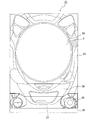
遊技機の一種であるパチンコ機21は、図1に示すように、長方形の外枠22に軸支された前面枠23を備えている。
Next, embodiments of the present invention will be described based on examples of the present invention. The present invention is not limited to the following examples and the like, and it goes without saying that the present invention can be implemented in various ways without departing from the gist of the present invention.
[Example 1]
As shown in FIG. 1, the
前面枠23に設けられた円形の窓24には板ガラスがはめ込まれており、その背後に遊技盤30(図2参照)が収納されている。
窓24の下方には上皿26、下皿27、発射ハンドル28等が取り付けられている。
A glass plate is fitted into a
Below the
図2に示すように、遊技盤30にはガイドレール31a、31bによって囲まれた略円形の遊技領域33が形成されている。その遊技領域33にはセンター役物32、センター役物32に組み付けられた演出図柄表示部10、ゲート34、始動領域となる始動入賞口35、同じく始動領域となる普通電動役物36、大入賞口37を有するアタッカー38等が配置されている。また、遊技盤30には、普通入賞口、遊技釘、風車等が配置されているが、これらは公知技術に従っているので図示と説明を省略する。
As shown in FIG. 2, the
次に、図3に従ってパチンコ機21の制御系を説明する。但し、図3には、制御系の主要部のみを示しており、本発明に関わりの薄い部分の図示は省略してある。
この制御系は遊技制御回路1を中心として構成されており、遊技制御回路1には払出制御回路4、発射制御回路5、中継基板6、外部出力端子板9、特別図柄表示部8が接続されている。また、図示は省略するが、遊技制御回路1には遊技盤30に装備されている各普通入賞口への入賞球をそれぞれ検出する入賞口スイッチ、始動入賞口35への入賞球を検出する始動口スイッチ、普通電動役物36への入賞球を検出する普通電役スイッチ、遊技球がゲート34を通過したことを検出する普通図柄始動スイッチ、大入賞口37への入賞球を計数するためのカウントスイッチ、大入賞口37を開閉するための大入賞口ソレノイドや普通電動役物36を開閉する普通役物ソレノイド等も接続されている。
Next, the control system of the
This control system is configured with a
遊技制御回路1は、遊技制御プログラムや不正防止用プログラム等を記憶したROM、遊技制御プログラムを実行することで遊技制御手段として機能するCPU及び演算等の作業領域として働くRAMを内蔵した8ビットワンチップマイコンを中心とした論理演算回路として構成され、これらの他に各回路又は各種スイッチ類及び各種アクチュエータ類との入出力を行う外部入出力回路も設けられている。
The
なお、遊技制御回路1のROMには遊技制御プログラムと不正防止用プログラムとが記憶されているが(但し、これらのみが記憶されているわけではない)、遊技制御回路1(8ビットワンチップマイコン)のメモリマップ上でアドレス0000H〜10FFHの範囲がエリア1となるアドレス空間として予め設定され、遊技制御プログラムは、そのエリア1内のアドレス0000H〜0E01Hの範囲に記憶されている。そして、不正防止用プログラムは、エリア1の末尾である10FFHに続く1100H〜1500Hの範囲に記憶されている。
The ROM of the
従って、遊技制御プログラムが記憶された遊技制御領域(0000H〜0E01H)と不正防止用プログラムが記憶された不正防止制御領域(1100H〜1500H)とが分離されている。このため、遊技制御プログラムと不正防止用プログラムの区別が容易であり、遊技制御プログラムの検査、チェックが簡単である。この結果、プログラム作成ミスの発生、プログラムの改竄を未然に防止する効果が期待できる。また、不正防止用プログラムが改竄されても遊技の性能には直接関係しないので、この点でも耐性が高い。 Therefore, the game control area (0000H to 0E01H) in which the game control program is stored and the fraud prevention control area (1100H to 1500H) in which the fraud prevention program is stored are separated. Therefore, it is easy to distinguish between the game control program and the fraud prevention program, and the game control program can be easily inspected and checked. As a result, it can be expected to prevent the occurrence of a program creation error and the alteration of the program. Further, even if the fraud prevention program is tampered with, it is not directly related to the performance of the game.
しかも、遊技制御領域と不正防止制御領域との間にはエリア1の余剰分(0E02H〜0E01H)が未使用の領域として存在するので、遊技制御領域と不正防止制御領域との分離が明瞭であり、上記の効果を向上させる。
Moreover, since the surplus area (0E02H to 0E01H) of
また、遊技制御回路1の8ビットワンチップマイコンのメモリマップにあってRAMに割り当てられているアドレス空間には、エリア2として予め設定されたアドレス空間があり、このエリア2の一部が遊技制御プログラムの作業領域として割付られる。そして、不正防止用プログラムの作業領域は、RAMに割り当てられているアドレス空間内ではあるがエリア2外になる領域に割付られている。
従って、RAMの作業領域においても不正防止用プログラムの作業領域とが分離される構成となり、RAMの作業領域においても遊技制御プログラムと不正防止用プログラムの区別が明瞭になっている。
The address space allocated to the RAM in the memory map of the 8-bit one-chip microcomputer of the
Accordingly, the work area of the anti-fraud program is separated from the work area of the RAM, and the distinction between the game control program and the anti-fraud program is clear also in the RAM work area.
遊技制御回路1には、上述の入賞口スイッチ、始動口スイッチ、普通電役スイッチ、普通図柄始動スイッチ、カウントスイッチ等の検出信号が入力される(始動信号等として図示)。
The
遊技制御回路1は搭載しているプログラムに従って動作して、上述の検出信号などに基づいて遊技の進行に関わる各種のコマンドを生成して払出制御回路4、発射制御回路5、サブ統合回路3に出力する。また遊技制御回路1は、特別図柄表示部8の表示を制御し、大入賞口ソレノイドや普通役物ソレノイド等の動作を制御する(ソレノイド等として図示)。
The
また、遊技制御回路1が出力する各種信号のうちから予め定められた何種類かの信号(例えば大当たり信号、確変信号等)が外部出力端子板9に出力される。この外部出力端子板9は図示しないホールコンピュータに接続される。
In addition, several kinds of predetermined signals (for example, jackpot signal, probability variation signal, etc.) among various signals output from the
払出制御回路4も遊技制御回路1と同様に、CPU、ROM、RAMを内蔵したワンチップマイコンを中心とした論理演算回路として構成されており、外部入出力回路も設けられている。遊技制御回路1と払出制御回路4とは双方向に通信可能である。
As with the
周知の通り、払出制御回路4は賞球を払い出すための払出装置(図示は省略)を制御する。また、払出制御回路4には、パチンコ機21(特に遊技盤30)に外部から及ぼされる磁力を検出するための磁気センサ7a、下皿27が満杯状態になったことを検出する満タンスイッチ7b、前面枠23が開放されたことを検出する扉開放スイッチ7c、パチンコ機21が振動させられたことを検出する振動センサ7dが接続されていて、これらからの検出信号が入力される。
As is well known, the
発射制御回路5も遊技制御回路1と同様に、CPU、ROM、RAMを内蔵したワンチップマイコンを中心とした論理演算回路として構成されており、外部入出力回路も設けられている。遊技制御回路1と発射制御回路5とは遊技制御回路1から発射制御回路5への一方向通信とされている。発射制御回路5は遊技球を発射するための発射装置(図示は省略)を制御する。
Similarly to the
特別図柄表示部8は、例えば7セグメント表示器によって構成されており、図柄の変動表示と静止表示(確定表示)とが可能である。
中継基板6はCPUを搭載していない基板である。中継基板6は遊技制御回路1からサブ統合回路3への通信を中継する基板であり、ノイズの除去や信号の変換を行うことがあってもデータの加工は行わない。
The special symbol display unit 8 is composed of, for example, a 7-segment display, and can perform variable display and static display (deterministic display) of symbols.
The
遊技制御回路1と中継基板6との通信は、遊技制御回路1から中継基板6への一方向通信とされ、中継基板6とサブ統合回路3との通信は、中継基板6からサブ統合回路3への一方向通信とされている。
Communication between the
そうした一方向通信を実現するために、遊技制御回路1には中継基板6との通信回路として、例えばインバータ、バッファ又はラッチ回路等の一方向通信回路が備えられている。また、中継基板6にも同様の一方向通信回路が備えられ、サブ統合回路3にも中継基板6との通信用に同様の一方向通信回路が備えられている。なお、このような一方向通信回路を遊技制御回路1、中継基板6及びサブ統合回路3のそれぞれに備えずとも、いずれか2者に備えれば、遊技制御回路1から中継基板6への通信及び中継基板6からサブ統合回路3への通信をともに一方向通信にできる。
In order to realize such one-way communication, the
サブ統合回路3と遊技制御回路1との間には、CPUを搭載しない中継基板6が介在し、中継基板6の前後の接続においては遊技制御回路1からのみサブ統合回路3に送信できる回路構成なので、不正行為が行い難く、不正行為の発見が容易であるという効果を発揮する。即ち、サブ統合回路3から遊技制御回路1に対して不正行為を行うためには、2重の一方向通信回路に対して不正行為を行う必要があり、また中継基板6はCPUを搭載しない基板なので中継基板6からの直接の不正行為は発覚し易いからである。まず、サブ統合回路3から遊技制御回路1に対して不正行為を行うためには、サブ統合回路3から遊技制御回路1に送信する配線を行う必要が生じる。しかしながら、遊技制御回路1とサブ統合回路3とは中継基板6を介して接続されているので、中継基板6を介さずにサブ統合回路3と遊技制御回路1とが接続された配線を不正行為によるものとみなすことができる。すなわち、不正行為による配線を発見するのが容易である。或いは、中継基板6から不正行為による配線より遊技制御回路1に対して不正遊技を行うことが考えられる。しかしながら、中継基板6はCPUを搭載しない基板として構成されているので、不正改造を容易に発見できる。
Between the
サブ統合回路3には、音・ランプアクチュエータ11と図柄制御回路2とが接続されており、図柄制御回路2には液晶表示装置である演出図柄表示部10が接続されている。
サブ統合回路3と音・ランプアクチュエータ11、図柄制御回路2との通信は、いずれもサブ統合回路3から音・ランプアクチュエータ11、図柄制御回路2への一方向通信とされている。同様に、図柄制御回路2と演出図柄表示部10との通信も図柄制御回路2から演出図柄表示部10への一方向通信とされている。
A sound /
Communication between the sub integrated
サブ統合回路3は、遊技制御回路1と同様にワンチップマイコン(CPU)を中心とした論理演算回路として構成されている。図柄制御回路2も遊技制御回路1と同様にワンチップマイコン(CPU)を中心とした論理演算回路として構成されている。
The
サブ統合回路3は、遊技制御回路1から送信されてくるデータを受信し、それらを画像制御用、電飾制御用及び効果音制御用のデータに振り分けて、電飾制御用と効果音制御用のデータは自身で使用し、画像制御用のデータは図柄制御回路2に送信する。また、遊技制御回路1から送られてきたデータに基づいてサブ統合回路3が生成したデータを画像制御用のデータとして図柄制御回路2に送信することもある。
The
サブ統合回路3に接続されている音・ランプアクチュエータ11は、主としてトランジスタ、音源IC及びアンプ等の駆動素子から構成されており、サブ統合回路3からの信号に基づいて音声信号を生成してスピーカを駆動し、また大当たりランプやエラーランプ等の各種LEDやランプ等を点灯する。つまり、サブ統合回路3は、電飾制御用及び効果音制御用のデータに基づいて生成した信号を音・ランプアクチュエータ11に出力することで、音声出力と電飾等の発光を制御する。
The sound /
図柄制御回路2は遊技制御回路1(実際にはサブ統合回路3)から送られてくるデータに基づいて画像を生成し、該生成した画像を演出図柄表示部10に表示させることで演出図柄表示部10の表示を制御する。
The
次に、特別図柄表示部8の表示制御に関係する遊技制御回路1の動作を説明する。
図4に示すのは遊技制御回路1が実行する特別図柄抽選処理のフローチャートである。なお、特別図柄抽選処理は遊技制御プログラムのサブルーチンの1つである。
Next, the operation of the
FIG. 4 is a flowchart of a special symbol lottery process executed by the
特別図柄抽選処理では遊技制御回路1は、まず始動口スイッチ又は普通電役スイッチの検出信号が入力されたか否か、すなわち始動入賞口35又は普通電動役物36に遊技球が入賞したか否かを判断する(S1)。ここで否定判断であればリターンする。一方、肯定判断であれば(S1:YES)、当否判定用乱数をランダムカウンタから読み込み、その読み込んだ当否判定用乱数が当たり値であるか否かの判定、すなわち当否抽選を行う(S2)。次に、当否判定用乱数とは別のランダムカウンタから読み込んだ変動時間決定用乱数に基づいて、変動時間を決定する(S3)。そして、S2における当否抽選の結果(当たりか外れか)を示すデータとS3で決定した変動時間を指定するデータとを変動開始コマンドとしてサブ統合回路3に送信する(S4)。
In the special symbol lottery process, the
続いて、遊技制御回路1は、特別図柄表示部8にて特別図柄の変動表示を開始させ(S5)、その変動時間がS3で決定した変動時間に達すればS2における当否抽選の結果(当たりか外れか)を示す特別図柄を確定表示させる(S6)。
Subsequently, the
一方、S4でサブ統合回路3に送信された変動開始コマンドは図柄制御回路2に送信される。図柄制御回路2は変動開始コマンドを受信すると、演出図柄表示部10に演出図柄の変動表示を開始させる。その演出図柄の変動表示は、変動開始コマンドにて示される当否抽選の結果(当たりか外れか)と変動時間とに基づいて図柄制御回路2が決定した変動パターンに従って行われる。そして、変動開始コマンドで指定された変動時間に達すれば、変動開始コマンドにて示される当否抽選の結果(当たりか外れか)を示す演出図柄を演出図柄表示部10に確定表示させる。
On the other hand, the variation start command transmitted to the sub integrated
遊技制御回路1は、当否抽選の結果が当たりであって、特別図柄表示部8に当たりを示す特別図柄を確定表示させたなら、周知の大当たり遊技を開始して大入賞口37を開放させる。
The
次に、不正防止に関係する遊技制御回路1及び払出制御回路4の動作を説明する。
まず、図5に示すフローチャートに従って、払出制御回路4が実行する不正検出処理を説明する。
Next, operations of the
First, the fraud detection process executed by the
この不正検出処理では、払出制御回路4は磁気センサ7a、扉開放スイッチ7c、振動センサ7dの検出信号を入力する(S11)。磁気センサ7aが磁気を検出しているか、扉開放スイッチ7cが前面枠23の開放を検出しているか、振動センサ7dがパチンコ機21の振動を検出しているときには、つまりいずれかの検出信号が検出レベルであれば(S12:YES)、不正を検出したことを示す信号を遊技制御回路1へ送信する(S13)。
In this fraud detection process, the
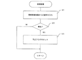
次に、図6に示すフローチャートに従って、遊技制御回路1が実行する受信処理を説明する。なお、この受信処理は遊技制御プログラムのサブルーチンの1つである。
受信処理では、遊技制御回路1は払出制御回路4からの信号を入力する(S21)。そして、上記の不正を検出したことを示す信号が払出制御回路4から送信されていたときには(S22:YES)、遊技制御プログラムの作業領域に不正フラグをセットする(S23)。
Next, the reception process executed by the
In the reception process, the
次に、図7に示すフローチャートに従って、遊技制御回路1が実行する発射停止処理を説明する。なお、この発射停止処理は遊技制御プログラムのサブルーチンの1つである。
発射停止処理では、不正フラグがセットされているか否かを判断し(S25)、これがセットされているときには(S25:YES)、発射停止信号を発射制御回路5に出力する(S26)。発射停止信号を受信した発射制御回路5は発射装置を停止させるのでパチンコ遊技を実行できなくなる。
Next, according to the flowchart shown in FIG. 7, the launch stop process executed by the
In the firing stop process, it is determined whether or not an illegal flag is set (S25). If this is set (S25: YES), a firing stop signal is output to the launch control circuit 5 (S26). The
次に、図8に示すフローチャートに従って、遊技制御回路1が実行する不正報知処理を説明する。なお、この不正報知処理は不正防止用プログラムのサブルーチンの1つである。
Next, the fraud notification process executed by the
不正報知処理では、不正フラグがセットされているか否かを判断し(S27)、これがセットされているときには(S27:YES)、不正信号を外部出力端子板9に出力する(S28)。外部出力端子板9はホールコンピュータに接続されるので、ホールコンピュータすなわち遊技店側は、この不正信号に基づいて不正に対処できる。 In the fraud notification process, it is determined whether or not the fraud flag is set (S27). When this flag is set (S27: YES), a fraud signal is output to the external output terminal board 9 (S28). Since the external output terminal board 9 is connected to the hall computer, the hall computer, that is, the game store side, can deal with the illegality based on the illegal signal.
なお、不正信号を外部出力端子板9に出力する他に(又は外部出力端子板9に出力せずに)図柄制御回路2に(サブ統合回路3経由で、または直接に)送信して、不正検出を報知する表示を演出図柄表示部10に表示させてもよい。
In addition to outputting an illegal signal to the external output terminal board 9 (or without outputting to the external output terminal board 9), the illegal signal is sent to the symbol control circuit 2 (via the
以上説明したように、遊技制御回路1のROMにては、遊技制御プログラムが記憶された遊技制御領域と不正防止用プログラムが記憶された不正防止制御領域とが分離されているので、遊技制御プログラムと不正防止用プログラムの区別が容易であり、遊技制御プログラムの検査、チェックが簡単である。この結果、プログラム作成ミスの発生、プログラムの改竄を未然に防止する効果が期待できる。また、不正防止用プログラムが改竄されても遊技の性能には直接関係しないので、この点でも耐性が高い。しかも、遊技制御領域と不正防止制御領域との間にはエリア1の余剰分が未使用の領域として存在するので、遊技制御領域と不正防止制御領域との分離が明瞭であり、上記の効果を向上させる。
As described above, in the ROM of the
また、遊技制御回路1のRAMに割り当てられているアドレス空間にはエリア2として予め設定されたアドレス空間があり、このエリア2の一部が遊技制御プログラムの作業領域として割付られ、不正防止用プログラムの作業領域はエリア2外になる領域に割付られている。従って、RAMの作業領域においても不正防止用プログラムの作業領域とが分離される構成となり、RAMの作業領域においても遊技制御プログラムと不正防止用プログラムの区別が明瞭になっている。
In addition, the address space allocated to the RAM of the
さらに、図3、図5〜8で示したように、不正検出手段である磁気センサ7a、扉開放スイッチ7c、振動センサ7dの検出信号を払出制御回路4に入力する構成として、遊技制御回路1には発射制御回路5、図柄制御回路2及び外部出力端子板9を接続した構成を採用している。なお、遊技制御回路1と図柄制御回路2とには中継基板6及びサブ統合回路3が介在しているが、遊技制御回路1と図柄制御回路2との接続が直接的でも間接的でもよいことは明らかである。
Further, as shown in FIGS. 3 and 5 to 8, the
払出制御回路4は、不正検出手段(磁気センサ7a、扉開放スイッチ7c又は振動センサ7d)のいずれかが検出レベルであれば、不正を検出したことを示す不正検出信号を遊技制御回路1へ送信し、遊技制御回路1は不正検出信号を受信すると、遊技制御プログラムの作業領域に不正フラグをセットする。そして、遊技制御回路1は、不正フラグがセットされていると、遊技制御プログラムに従って、発射の停止を指示するための発射停止信号を発射制御回路5に出力し、発射停止信号を受信した発射制御回路5は発射装置を停止させる。また、遊技制御回路1は、不正フラグがセットされていると、不正防止用プログラムに従って、不正信号を外部出力端子板9に出力する。
The
上記のような構成及び動作であり、不正検出を払出制御回路4が行い、発射停止を遊技制御回路1が行うので、面替え時の有効活用が図れると共に、遊技の性能に関する制御を遊技制御回路1が統一制御する妨げにはならない。また、発射を停止するための不正フラグは遊技制御プログラムの作業領域を使用し、不正防止用プログラムの作業領域を使用しないので、遊技制御プログラムの作業領域に不正行為が行われないようチェックするだけでよい。不正防止用プログラムの作業領域のデータが改竄されても遊技の性能に直接影響を与えない。
With the configuration and operation as described above, the
更に、発射停止は遊技制御プログラムが実行し、不正防止用プログラムは外部出力端子板9に出力する構成なので(上述した通り、不正検出を演出図柄表示部10に表示させてもよい。)、遊技制御プログラムをセキュリティチェックプログラム等によりチェックするだけでよく、不正防止用プログラムが改竄されても遊技の性能に影響を与えない。 Further, since the game control program is executed to stop firing and the fraud prevention program is output to the external output terminal board 9 (as described above, fraud detection may be displayed on the effect symbol display unit 10). The control program only needs to be checked by a security check program or the like, and even if the anti-fraud program is tampered with, it does not affect game performance.
実施例で遊技機の一例として示したパチンコ機21は、
遊技の進行を制御するための遊技制御プログラムを記憶した遊技制御領域と、不正行為を防止するための不正防止用プログラムを記憶した不正防止制御領域とを分離したROMを搭載した遊技制御回路と、
景品体の払出を制御する払出制御回路とを備え、
前記払出制御回路には、該遊技機に外部から及ぼされる磁力を検出するための磁気センサ、前面枠が開放されたことを検出する扉開放スイッチ又は該遊技機が振動させられたことを検出する振動センサのいずれかを接続し、
前記遊技制御回路には、発射制御回路、図柄制御回路及び外部接続端子板を接続し、
前記払出制御回路は、前記磁気センサ、扉開放スイッチ又は振動センサの検出信号が検出レベルであれば、その旨を示す不正検出信号を前記遊技制御回路へ送信し、
前記遊技制御回路は、不正検出信号を受信すると遊技制御プログラムの作業領域に不正フラグをセットし、
前記遊技制御回路は、前記不正フラグがセットされていれば、不正防止用制御領域のプログラムに従って発射の停止を指示するための信号を発射制御回路に出力し、
また不正防止用制御領域のプログラムに従って不正を通報するための信号を外部出力端子板に出力する
構成になっており、そのような構成の遊技機とすれば、
上記の通りに、不正検出を払出制御回路が行い、発射停止を遊技制御回路が行うので、面替え時の有効活用が図れると共に、遊技の性能に関する制御を遊技制御回路が統一制御する妨げにはならない。また、発射を停止するための不正フラグは遊技制御プログラムの作業領域を使用し、不正防止用プログラムの作業領域を使用しないので、遊技制御プログラムの作業領域に不正行為が行われないようチェックするだけでよい。不正防止用プログラムの作業領域のデータが改竄されても遊技の性能に直接影響を与えない。更に、発射停止は遊技制御プログラムが実行し、不正防止用プログラムは外部出力端子板に出力する構成なので(なお、不正検出を演出図柄表示部に表示させてもよい。)、遊技制御プログラムをセキュリティチェックプログラム等によりチェックするだけでよく、不正防止用プログラムが改竄されても遊技の性能に影響を与えない。
[変形例1]
実施例ではアドレス0000H〜10FFHの範囲をエリア1として設定し、遊技制御プログラムはエリア1内に記憶し、不正防止用プログラムはエリア1を外れたアドレスに記憶することで、遊技制御プログラムが記憶された遊技制御領域と不正防止用プログラムが記憶された不正防止制御領域との間に、少なくともエリア1の余剰分を未使用の領域として存在させて、遊技制御領域と不正防止制御領域とを分離させているが、
例えば遊技制御プログラムが記憶された遊技制御領域を0000H〜0E01H、これに続く0E02H〜0EFFHを未使用領域、不正防止用プログラムが記憶された不正防止制御領域を0F00H〜1300Hというように、遊技制御領域と不正防止制御領域との間に未使用領域を介在させて、遊技制御領域と不正防止制御領域とを分離してもよい。このようにしても、遊技制御プログラムと不正防止用プログラムの区別が容易であり、遊技制御プログラムの検査、チェックが簡単である。この結果、プログラム作成ミスの発生、プログラムの改竄を未然に防止する効果が期待できる。また、不正防止用プログラムが改竄されても遊技の性能には直接関係しないので、この点でも耐性が高い。
[変形例2]
図9に示すように、発射制御回路5を払出制御回路4に接続し、また払出制御回路4には外部出力端子板9aを接続した構成とすることもできる。
The
A game control circuit equipped with a ROM in which a game control area for storing a game control program for controlling the progress of a game and a fraud prevention control area for storing a fraud prevention program for preventing fraud are separated;
A payout control circuit for controlling the payout of the prize body,
The payout control circuit detects a magnetic sensor for detecting a magnetic force exerted on the gaming machine from the outside, a door opening switch for detecting that the front frame is opened, or detecting that the gaming machine is vibrated. Connect one of the vibration sensors,
The game control circuit is connected to a launch control circuit, a symbol control circuit and an external connection terminal board,
If the detection signal of the magnetic sensor, door opening switch or vibration sensor is a detection level, the payout control circuit transmits a fraud detection signal indicating that to the game control circuit,
When the game control circuit receives a fraud detection signal, it sets a fraud flag in the work area of the game control program,
If the fraud flag is set, the game control circuit outputs a signal for instructing the stop of the firing according to the program of the fraud prevention control area,
In addition, it is configured to output a signal for reporting fraud to the external output terminal board according to the program of the control area for fraud prevention, and if it is a gaming machine of such a configuration,
As described above, the payout control circuit performs fraud detection, and the game control circuit performs launch stop, so that it can be used effectively at the time of face change, and it prevents the game control circuit from performing unified control over control related to game performance. Don't be. In addition, since the fraud flag for stopping the launch uses the work area of the game control program and does not use the work area of the fraud prevention program, it is only necessary to check that the illegal action is not performed in the work area of the game control program. It's okay. Even if the data in the work area of the fraud prevention program is altered, it does not directly affect the performance of the game. Furthermore, since the game control program is executed to stop the launch and the fraud prevention program is output to the external output terminal board (note that fraud detection may be displayed on the effect symbol display section), the game control program is secured. It is only necessary to check with a check program or the like, and even if the fraud prevention program is tampered with, it does not affect the performance of the game.
[Modification 1]
In the embodiment, the range of addresses 0000H to 10FFH is set as
For example, the game control area in which the game control program is stored is 0000H to 0E01H, the subsequent 0E02H to 0EFFH is the unused area, and the anti-fraud control area in which the anti-fraud program is stored is 0F00H to 1300H. The game control area and the fraud prevention control area may be separated by interposing an unused area between the game control area and the fraud prevention control area. Even in this case, it is easy to distinguish between the game control program and the fraud prevention program, and the inspection and check of the game control program is simple. As a result, it can be expected to prevent the occurrence of a program creation error and the alteration of the program. Further, even if the fraud prevention program is tampered with, it is not directly related to the performance of the game.
[Modification 2]
As shown in FIG. 9, the
この場合、払出制御回路4が実行する不正検出処理は図10のように変形される。すなわち、不正検出手段の検出信号を入力し(S11)、いずれかの検出信号が検出レベルであるか否かを判断する(S12)までは同じであるが、S12で肯定判断のときに、不正信号を外部出力端子板9aに出力し(S15)、発射停止信号を発射制御回路5に出力する(S16)点で異なる。
In this case, the fraud detection process executed by the
一方、遊技制御回路1は、図6〜8に示す処理を行う必要がなくなり、不正防止用プログラムによって、例えば大入賞口37が開放していないのにカウントスイッチからの入賞信号が入力された等の遊技上の不正を検出し、不正を検出すれば外部出力端子板9に不正信号を出力するといった処理を行う。なお、不正信号は払出制御回路4を介して外部出力端子板9aに出力してもよい。
On the other hand, the
このように構成すれば、払出制御回路4が不正検出手段(磁気センサ7a、扉開放スイッチ7c又は振動センサ7d)により不正行為を検出し、発射停止、外部出力端子板9aへの出力制御を行うので、面替え時の有効利用が一層図れる。また、アタッカーのソレノイドをオンしていない状態で入賞検出される等の異常(不正)は遊技制御回路1が行い外部出力端子板9に出力する構成なので、プログラムにより遊技の進行上異常と判断される不正と、遊技機に対する物理的作用を及ぼす不正とを明確に区別した処理を各回路1、4で実行することができる。
With this configuration, the
変形例2に示した遊技機は、
遊技の進行を制御する遊技制御回路と、
景品体の払出を制御するための払出制御プログラムを記憶した払出制御領域と、不正行為を防止するための不正防止用プログラムを記憶した不正防止制御領域とを分離した払出制御回路用のROMを備えた払出制御回路とを備え、
前記払出制御回路には、該遊技機に外部から及ぼされる磁力を検出するための磁気センサ、前面枠が開放されたことを検出する扉開放スイッチ又は該遊技機が振動させられたことを検出する振動センサのいずれかと、発射制御回路及び外部接続端子板とを接続し、
前記払出制御回路は、前記磁気センサ、扉開放スイッチ又は振動センサの検出信号が検出レベルであれば、不正防止用制御領域のプログラムに従って発射の停止を指示するための信号を発射制御回路に出力し、また不正防止用制御領域のプログラムに従って不正を通報するための信号を外部出力端子板に出力する
構成になっており、そのような構成の遊技機とすれば、
上記の通りに、払出制御回路が不正検出手段(磁気センサ、扉開放スイッチ又は振動センサ)により不正行為を検出し、発射停止、外部出力端子板への出力制御を行うので、面替え時の有効利用が一層図れる。また、アタッカーのソレノイドをオンしていない状態で入賞検出される等の異常(不正)は遊技制御回路が行い外部出力端子板に出力する構成なので、プログラムにより遊技の進行上異常と判断される不正と、遊技機に対する物理的作用を及ぼす不正(センサ等が感知(ON)すれば異常と判断される不正)とを明確に区別した処理を遊技制御回路と払出制御回路とで実行することができる。
The gaming machine shown in
A game control circuit for controlling the progress of the game;
Provided with a ROM for a payout control circuit in which a payout control area for storing a payout control program for controlling the payout of prizes and a fraud prevention control area for storing a fraud prevention program for preventing fraud With a payout control circuit,
The payout control circuit detects a magnetic sensor for detecting a magnetic force exerted on the gaming machine from the outside, a door opening switch for detecting that the front frame is opened, or detecting that the gaming machine is vibrated. Connect one of the vibration sensors to the launch control circuit and the external connection terminal board,
If the detection signal of the magnetic sensor, door opening switch or vibration sensor is at a detection level, the payout control circuit outputs a signal for instructing the stop of the emission to the launch control circuit according to the program in the control area for fraud prevention. In addition, it is configured to output a signal for reporting fraud to the external output terminal board according to the program of the control area for fraud prevention, and if it is a gaming machine of such configuration,
As described above, the payout control circuit detects fraudulent acts by fraud detection means (magnetic sensor, door opening switch or vibration sensor), and stops firing and controls output to the external output terminal board. It can be used further. In addition, since the game control circuit performs an abnormality such as a winning detection when the solenoid of the attacker is not turned on and outputs it to the external output terminal board, it is an illegality that is judged as an abnormality in the progress of the game by the program. And the game control circuit and the payout control circuit can execute a process that clearly distinguishes between the game and the fraud that exerts a physical action on the gaming machine (the fraud that is determined to be abnormal if the sensor or the like senses (ON)). .
なお、上記の遊技機において、「遊技の進行を制御するための遊技制御プログラムを記憶した遊技制御領域と、不正行為を防止するための不正防止用プログラムを記憶した不正防止制御領域とを分離したROMを搭載した遊技制御回路」を採用できることは言うまでもない。
[その他]
実施例及び変形例では不正検出手段として磁気センサ7a、扉開放スイッチ7c及び振動センサ7dを備えているが、不正検出手段として機能するセンサ類は少なくとも1つあればよい。
In the above gaming machine, “a game control area storing a game control program for controlling the progress of the game and a fraud prevention control area storing a fraud prevention program for preventing fraud are separated. It goes without saying that a “game control circuit equipped with a ROM” can be adopted.
[Others]
In the embodiment and the modification, the magnetic sensor 7a, the door opening switch 7c, and the vibration sensor 7d are provided as the fraud detection means. However, at least one sensor that functions as the fraud detection means is sufficient.
また、実施例では遊技制御プログラムと不正防止用プログラムとを記憶したROMを搭載した遊技制御回路について説明したが、
景品体の払出を制御するための払出制御プログラムと不正行為を防止するための不正防止用プログラムを記憶した払出制御回路用のROMにおいても、実施例と同様に払出制御プログラムを記憶した払出制御領域と不正防止用プログラムを記憶した不正防止制御領域とを分離した構成を採用することができる。
In the embodiment, a game control circuit equipped with a ROM storing a game control program and a fraud prevention program has been described.
In the ROM for the payout control circuit storing the payout control program for controlling the payout of the prize and the fraud prevention program for preventing fraud, the payout control area storing the payout control program as in the embodiment. And the anti-fraud control area storing the anti-fraud program can be employed.
そうすれば、払出制御プログラムと不正防止用プログラムの区別が容易であり、払出制御プログラムの検査、チェックが簡単である。この結果、プログラム作成ミスの発生、プログラムの改竄を未然に防止する効果が期待でき、不正防止用プログラムが改竄されても遊技の性能には直接関係しないので、この点でも耐性が高いという、実施例と同様の効果が払出制御回路用のROMにおいても得られる。 Then, the payout control program and the fraud prevention program can be easily distinguished, and the payout control program can be easily inspected and checked. As a result, it can be expected to prevent program creation mistakes and program tampering, and even if the anti-fraud program is tampered with, it is not directly related to game performance. The same effect as the example can be obtained in the ROM for the payout control circuit.
また、そのような払出制御回路用のROMでは、前記払出制御領域を予め設定されたアドレス空間(以下、「エリア1」という)内に収め、前記払出制御プログラムが前記エリア1を満たさなくとも不正防止用プログラムを前記エリア1外に記憶するができる。
Further, in such a ROM for the payout control circuit, the payout control area is stored in a preset address space (hereinafter referred to as “
或いは、そのような払出制御回路用のROMでは、前記払出制御領域と前記不正防止制御領域との間に未使用領域を介在させた構成にもできる。
上記の払出制御回路用のROMを備える払出制御回路は、当該払出制御回路用のROMと、該ROMに記憶されている前記払出制御プログラム及び前記不正防止用プログラムを実行するCPUと、前記CPUがアクセスするRAMとを備える払出制御回路において、前記RAMは、前記払出制御プログラムの作業領域と、前記不正防止用プログラムの作業領域とが分離される構成とすればよい。
Alternatively, such a ROM for the payout control circuit may be configured such that an unused area is interposed between the payout control area and the fraud prevention control area.
The payout control circuit including the payout control circuit ROM includes a ROM for the payout control circuit, a CPU that executes the payout control program and the fraud prevention program stored in the ROM, and the CPU In the payout control circuit including the RAM to be accessed, the RAM may be configured such that the work area of the payout control program and the work area of the fraud prevention program are separated.
そのように構成した遊技制御回路は、上述の払出制御回路用のROMを備えるから、上記の効果を有する。また、RAMは、払出制御プログラムの作業領域と、不正防止用プログラムの作業領域とが分離される構成であるから、RAMの作業領域においても払出制御プログラムと不正防止用プログラムの区別が明瞭である。 The game control circuit configured as described above has the above-described effect because it includes the above-described payout control circuit ROM. Further, since the RAM has a configuration in which the work area of the payout control program and the work area of the fraud prevention program are separated, the distinction between the payout control program and the fraud prevention program is also clear in the RAM work area. .
また、そのように構成した遊技制御回路では、前記RAMでは、前記払出制御プログラムの作業領域を予め設定されたアドレス空間(以下、「エリア2」という)内に収め、前記不正防止用プログラムの作業領域を前記エリア2外にすることができる。
In the gaming control circuit configured as described above, in the RAM, the work area of the payout control program is stored in a preset address space (hereinafter referred to as “
1・・・遊技制御回路、
3・・・サブ統合回路、
4・・・払出制御回路、
5・・・発射制御回路、
6・・・中継基板、
7a・・・磁気センサ、
7c・・・扉開放スイッチ、
7d・・・振動センサ、
8・・・特別図柄表示部、
9・・・外部出力端子板、
9a・・・外部出力端子板、
10・・・演出図柄表示部、
11・・・音・ランプアクチュエータ、
21・・・パチンコ機、
30・・・遊技盤、
32・・・センター役物、
33・・・遊技領域、
34・・・ゲート、
35・・・始動入賞口、
36・・・普通電動役物、
37・・・大入賞口。
1 ... Game control circuit,
3 ... Sub-integrated circuit,
4 ... Dispensing control circuit,
5 ... Launch control circuit,
6 ... Relay board,
7a: Magnetic sensor,
7c ... Door opening switch,
7d: Vibration sensor,
8 ... Special symbol display part,
9 ... External output terminal board,
9a ... external output terminal board,
10 ... Production symbol display section,
11 ... Sound / lamp actuator,
21 ... Pachinko machine,
30 ... game board,
32 ... Center character,
33 ... gaming area,
34 ... Gate,
35 ... Starting prize opening,
36: Ordinary electric equipment,
37 ... The big prize opening.
Claims (1)
賞球に係る制御をするための賞球制御プログラムを記憶した賞球制御領域と、不正行為を防止するための賞球不正防止用プログラムを記憶した賞球不正防止制御領域とを分離したROMと、該ROMに記憶されている前記賞球制御プログラム及び前記賞球不正防止用プログラムを実行するCPUと、前記CPUがアクセスするRAMとを備える賞球制御回路と、を有し、
該RAMは、前記賞球制御プログラムの作業領域と、前記不正防止用プログラムの作業領域とが分離されることを特徴とする遊技機であって、
前記賞球制御回路には、当該遊技機に外部から及ぼされる磁力を検出するための磁気センサと、前面枠が開放されたことを検出する扉開放スイッチと、当該遊技機が振動させられたことを検出する振動センサとのうちの少なくとも一つを接続し、
前記遊技制御回路には、発射制御回路が接続されていると共に、遊技の進行を制御するための遊技制御プログラムを記憶した遊技制御領域と、不正行為を防止するための遊技不正防止用プログラムを記憶した遊技不正防止制御領域とを分離したROMと、該ROMに記憶されている前記遊技制御プログラム及び前記遊技不正防止用プログラムを実行するCPUと、前記CPUがアクセスし、前記遊技制御プログラムの作業領域と、前記遊技不正防止用プログラムの作業領域とが分離されるRAMと、を備え、
前記賞球制御回路は、前記磁気センサ、前記扉開放スイッチ、または、前記振動センサの検出信号が検出レベルであれば、その旨を示す不正検出信号を前記遊技制御回路へ送信し、
前記遊技制御回路は、前記不正検出信号を受信すると、前記RAMにおける前記遊技制御プログラムの作業領域に不正フラグをセットし、
前記遊技制御回路は、前記不正フラグがセットされていれば、発射の停止を指示するための信号を前記発射制御回路に出力すること、
を特徴とする遊技機。 A game control circuit for controlling the progress of the game;
A prize balls control region which stores prize balls control program for the control of the prize balls, a ROM that separate the winning balls fraud control region which stores winning balls fraud prevention program for preventing abuse A prize ball control circuit comprising: a CPU for executing the prize ball control program and the prize ball fraud prevention program stored in the ROM; and a RAM accessed by the CPU;
The RAM is a gaming machine in which a work area of the prize ball control program and a work area of the fraud prevention program are separated,
The prize ball control circuit includes a magnetic sensor for detecting a magnetic force exerted on the gaming machine from the outside, a door opening switch for detecting that the front frame is opened, and the gaming machine is vibrated. Connecting at least one of the vibration sensor and
The game control circuit is connected to a launch control circuit and stores a game control area storing a game control program for controlling the progress of the game and a game fraud prevention program for preventing fraud A ROM that is separated from the gaming fraud prevention control area, a CPU that executes the game control program and the game fraud prevention program stored in the ROM, and a work area of the game control program that is accessed by the CPU And a RAM for separating a work area of the gaming fraud prevention program,
If the detection signal of the magnetic sensor, the door opening switch, or the vibration sensor is a detection level, the prize ball control circuit transmits a fraud detection signal indicating that to the game control circuit,
When the game control circuit receives the fraud detection signal, the game control circuit sets a fraud flag in a work area of the game control program in the RAM ,
The game control circuit, if the fraud flag is set, outputs a signal for instructing the stop of the launch to the launch control circuit;
A gaming machine characterized by
Priority Applications (1)
| Application Number | Priority Date | Filing Date | Title |
|---|---|---|---|
| JP2008052083A JP5552609B2 (en) | 2008-03-03 | 2008-03-03 | Game machine |
Applications Claiming Priority (1)
| Application Number | Priority Date | Filing Date | Title |
|---|---|---|---|
| JP2008052083A JP5552609B2 (en) | 2008-03-03 | 2008-03-03 | Game machine |
Related Child Applications (2)
| Application Number | Title | Priority Date | Filing Date |
|---|---|---|---|
| JP2013207830A Division JP5838395B2 (en) | 2013-10-03 | 2013-10-03 | Game machine |
| JP2014078481A Division JP5853244B2 (en) | 2014-04-07 | 2014-04-07 | Game machine |
Publications (3)
| Publication Number | Publication Date |
|---|---|
| JP2009207609A JP2009207609A (en) | 2009-09-17 |
| JP2009207609A5 JP2009207609A5 (en) | 2011-03-17 |
| JP5552609B2 true JP5552609B2 (en) | 2014-07-16 |
Family
ID=41181363
Family Applications (1)
| Application Number | Title | Priority Date | Filing Date |
|---|---|---|---|
| JP2008052083A Active JP5552609B2 (en) | 2008-03-03 | 2008-03-03 | Game machine |
Country Status (1)
| Country | Link |
|---|---|
| JP (1) | JP5552609B2 (en) |
Families Citing this family (54)
| Publication number | Priority date | Publication date | Assignee | Title |
|---|---|---|---|---|
| JP5514982B2 (en) * | 2010-06-15 | 2014-06-04 | 株式会社高尾 | Microcomputer chip for gaming machine control |
| JP6503704B2 (en) * | 2014-11-27 | 2019-04-24 | サミー株式会社 | Gaming machine |
| JP6582399B2 (en) * | 2014-11-27 | 2019-10-02 | サミー株式会社 | Game machine |
| JP6503705B2 (en) * | 2014-11-27 | 2019-04-24 | サミー株式会社 | Gaming machine |
| JP6503706B2 (en) * | 2014-11-27 | 2019-04-24 | サミー株式会社 | Gaming machine |
| JP6578652B2 (en) * | 2014-11-27 | 2019-09-25 | サミー株式会社 | Game machine |
| JP6387808B2 (en) * | 2014-11-27 | 2018-09-12 | サミー株式会社 | Game machine |
| JP6592888B2 (en) * | 2014-11-27 | 2019-10-23 | サミー株式会社 | Game machine |
| JP6432310B2 (en) * | 2014-11-27 | 2018-12-05 | サミー株式会社 | Game machine |
| JP6592889B2 (en) * | 2014-11-27 | 2019-10-23 | サミー株式会社 | Game machine |
| JP6578653B2 (en) * | 2014-11-27 | 2019-09-25 | サミー株式会社 | Game machine |
| JP6507593B2 (en) * | 2014-11-27 | 2019-05-08 | サミー株式会社 | Gaming machine |
| JP6532720B2 (en) * | 2015-03-20 | 2019-06-19 | 株式会社三共 | Gaming machine |
| JP6604028B2 (en) * | 2015-04-28 | 2019-11-13 | サミー株式会社 | Game machine |
| JP6604027B2 (en) * | 2015-04-28 | 2019-11-13 | サミー株式会社 | Game machine |
| JP6600488B2 (en) * | 2015-05-27 | 2019-10-30 | 株式会社三共 | Slot machine |
| JP6891940B2 (en) * | 2015-06-15 | 2021-06-18 | 株式会社三洋物産 | Pachinko machine |
| JP6677984B2 (en) * | 2015-08-05 | 2020-04-08 | 株式会社三共 | Gaming machine |
| JP6816940B2 (en) * | 2015-08-05 | 2021-01-20 | 株式会社三共 | Game machine |
| JP6816939B2 (en) * | 2015-08-05 | 2021-01-20 | 株式会社三共 | Game machine |
| JP6677985B2 (en) * | 2015-08-05 | 2020-04-08 | 株式会社三共 | Gaming machine |
| JP6033384B1 (en) * | 2015-10-05 | 2016-11-30 | 山佐株式会社 | Game machine |
| JP6660142B2 (en) * | 2015-10-16 | 2020-03-04 | 株式会社三共 | Gaming machine |
| JP6679097B2 (en) * | 2015-11-04 | 2020-04-15 | サミー株式会社 | Slot machine |
| JP6466859B2 (en) * | 2016-01-08 | 2019-02-06 | 株式会社オリンピア | Game machine |
| JP6298478B2 (en) * | 2016-01-08 | 2018-03-20 | 株式会社オリンピア | Game machine |
| JP6298477B2 (en) * | 2016-01-08 | 2018-03-20 | 株式会社オリンピア | Game machine |
| JP6738161B2 (en) * | 2016-03-01 | 2020-08-12 | 株式会社三共 | Amusement machine |
| JP6630200B2 (en) * | 2016-03-15 | 2020-01-15 | 株式会社オリンピア | Gaming machine |
| JP2017164252A (en) * | 2016-03-15 | 2017-09-21 | 株式会社オリンピア | Game machine |
| JP6490617B2 (en) * | 2016-03-25 | 2019-03-27 | 株式会社ニューギン | Game machine |
| JP6490616B2 (en) * | 2016-03-25 | 2019-03-27 | 株式会社ニューギン | Game machine |
| JP6484580B2 (en) * | 2016-03-25 | 2019-03-13 | 株式会社ニューギン | Game machine |
| JP6484579B2 (en) * | 2016-03-25 | 2019-03-13 | 株式会社ニューギン | Game machine |
| JP2017184776A (en) * | 2016-03-31 | 2017-10-12 | サミー株式会社 | Pachinko game machine |
| JP6134843B1 (en) * | 2016-05-25 | 2017-05-24 | 山佐株式会社 | Game machine |
| JP2018027136A (en) * | 2016-08-15 | 2018-02-22 | 株式会社ユニバーサルエンターテインメント | Game machine |
| JP6566919B2 (en) * | 2016-08-15 | 2019-08-28 | 株式会社ユニバーサルエンターテインメント | Game machine |
| JP6539628B2 (en) * | 2016-09-21 | 2019-07-03 | サミー株式会社 | Gaming machine |
| JP6471131B2 (en) * | 2016-09-30 | 2019-02-13 | 株式会社三共 | Slot machine |
| JP6785116B2 (en) * | 2016-10-13 | 2020-11-18 | 株式会社平和 | Game machine |
| JP6228650B2 (en) * | 2016-10-25 | 2017-11-08 | 山佐株式会社 | Game machine |
| JP6360941B2 (en) * | 2017-04-21 | 2018-07-18 | 山佐株式会社 | Game machine |
| JP6495977B2 (en) * | 2017-07-21 | 2019-04-03 | 株式会社藤商事 | Game machine |
| JP6503434B2 (en) * | 2017-10-13 | 2019-04-17 | 山佐株式会社 | Gaming machine |
| JP6450955B2 (en) * | 2017-12-05 | 2019-01-16 | 株式会社オリンピア | Game machine |
| JP2018086348A (en) * | 2018-02-15 | 2018-06-07 | 株式会社オリンピア | Game machine |
| JP6792010B2 (en) * | 2019-02-26 | 2020-11-25 | 株式会社ニューギン | Game machine |
| JP6792009B2 (en) * | 2019-02-26 | 2020-11-25 | 株式会社ニューギン | Game machine |
| JP6756893B2 (en) * | 2019-11-27 | 2020-09-16 | 株式会社三共 | Game machine |
| JP6792691B2 (en) * | 2019-11-27 | 2020-11-25 | 株式会社三共 | Game machine |
| JP6792692B2 (en) * | 2019-11-27 | 2020-11-25 | 株式会社三共 | Game machine |
| JP2021062249A (en) * | 2021-01-14 | 2021-04-22 | 株式会社三洋物産 | Game machine |
| JP2021062250A (en) * | 2021-01-14 | 2021-04-22 | 株式会社三洋物産 | Game machine |
Family Cites Families (5)
| Publication number | Priority date | Publication date | Assignee | Title |
|---|---|---|---|---|
| JP3029611B1 (en) * | 1999-01-26 | 2000-04-04 | 株式会社藤商事 | Gaming machine |
| JP2003190447A (en) * | 2001-12-26 | 2003-07-08 | Takao:Kk | Pachinko game machine |
| JP2006288409A (en) * | 2005-04-05 | 2006-10-26 | Takeya Co Ltd | Game machine and game hall management system |
| JP2007020821A (en) * | 2005-07-14 | 2007-02-01 | Three Stone:Kk | Abnormal vibration detector of game machine, abnormal vibration detection method of game machine and computer program |
| JP4868975B2 (en) * | 2006-08-18 | 2012-02-01 | 株式会社大一商会 | Game machine |
-
2008
- 2008-03-03 JP JP2008052083A patent/JP5552609B2/en active Active
Also Published As
| Publication number | Publication date |
|---|---|
| JP2009207609A (en) | 2009-09-17 |
Similar Documents
| Publication | Publication Date | Title |
|---|---|---|
| JP5552609B2 (en) | Game machine | |
| JP5853244B2 (en) | Game machine | |
| JP5457390B2 (en) | Game machine | |
| JP5467239B2 (en) | Bullet ball machine | |
| JP2008055049A (en) | Game machine | |
| JP2017192472A (en) | Pinball game machine | |
| JP2009039323A (en) | Pachinko game machine | |
| JP5303706B2 (en) | Bullet ball machine | |
| JP6047710B2 (en) | Amusement stand | |
| JP2009005920A (en) | Game machine | |
| JP5838395B2 (en) | Game machine | |
| JP2008245899A (en) | Game machine and game hall system | |
| JP5971741B2 (en) | Game machine | |
| JP2008220486A (en) | Pinball game machine | |
| JP2014057740A (en) | Game machine | |
| JP5020531B2 (en) | Pachinko machine | |
| JP5303699B2 (en) | Game machine | |
| JP2016172168A (en) | Game machine | |
| JP2007020807A (en) | Game control device | |
| JP5604557B2 (en) | Bullet ball machine | |
| JP5514986B2 (en) | Bullet ball machine | |
| JP5417593B2 (en) | Bullet ball machine | |
| JP5417594B2 (en) | Bullet ball machine | |
| JP5124726B2 (en) | Bullet ball machine | |
| JP2013075121A (en) | Game machine |
Legal Events
| Date | Code | Title | Description |
|---|---|---|---|
| A521 | Written amendment |
Free format text: JAPANESE INTERMEDIATE CODE: A523 Effective date: 20110131 |
|
| A621 | Written request for application examination |
Free format text: JAPANESE INTERMEDIATE CODE: A621 Effective date: 20110131 |
|
| A977 | Report on retrieval |
Free format text: JAPANESE INTERMEDIATE CODE: A971007 Effective date: 20130124 |
|
| A131 | Notification of reasons for refusal |
Free format text: JAPANESE INTERMEDIATE CODE: A131 Effective date: 20130129 |
|
| A521 | Written amendment |
Free format text: JAPANESE INTERMEDIATE CODE: A523 Effective date: 20130228 |
|
| A131 | Notification of reasons for refusal |
Free format text: JAPANESE INTERMEDIATE CODE: A131 Effective date: 20130820 |
|
| A521 | Written amendment |
Free format text: JAPANESE INTERMEDIATE CODE: A523 Effective date: 20131008 |
|
| TRDD | Decision of grant or rejection written | ||
| A01 | Written decision to grant a patent or to grant a registration (utility model) |
Free format text: JAPANESE INTERMEDIATE CODE: A01 Effective date: 20140401 |
|
| A61 | First payment of annual fees (during grant procedure) |
Free format text: JAPANESE INTERMEDIATE CODE: A61 Effective date: 20140408 |
|
| R150 | Certificate of patent or registration of utility model |
Ref document number: 5552609 Country of ref document: JP Free format text: JAPANESE INTERMEDIATE CODE: R150 |
|
| R250 | Receipt of annual fees |
Free format text: JAPANESE INTERMEDIATE CODE: R250 |
|
| R250 | Receipt of annual fees |
Free format text: JAPANESE INTERMEDIATE CODE: R250 |