JP5512552B2 - 竪型遠心分離装置 - Google Patents
竪型遠心分離装置 Download PDFInfo
- Publication number
- JP5512552B2 JP5512552B2 JP2010547451A JP2010547451A JP5512552B2 JP 5512552 B2 JP5512552 B2 JP 5512552B2 JP 2010547451 A JP2010547451 A JP 2010547451A JP 2010547451 A JP2010547451 A JP 2010547451A JP 5512552 B2 JP5512552 B2 JP 5512552B2
- Authority
- JP
- Japan
- Prior art keywords
- bowl
- casing
- discharge member
- liquid
- vertical
- Prior art date
- Legal status (The legal status is an assumption and is not a legal conclusion. Google has not performed a legal analysis and makes no representation as to the accuracy of the status listed.)
- Active
Links
Images


Classifications
-
- B—PERFORMING OPERATIONS; TRANSPORTING
- B04—CENTRIFUGAL APPARATUS OR MACHINES FOR CARRYING-OUT PHYSICAL OR CHEMICAL PROCESSES
- B04B—CENTRIFUGES
- B04B1/00—Centrifuges with rotary bowls provided with solid jackets for separating predominantly liquid mixtures with or without solid particles
- B04B1/02—Centrifuges with rotary bowls provided with solid jackets for separating predominantly liquid mixtures with or without solid particles without inserted separating walls
-
- B—PERFORMING OPERATIONS; TRANSPORTING
- B04—CENTRIFUGAL APPARATUS OR MACHINES FOR CARRYING-OUT PHYSICAL OR CHEMICAL PROCESSES
- B04B—CENTRIFUGES
- B04B11/00—Feeding, charging, or discharging bowls
- B04B11/04—Periodical feeding or discharging; Control arrangements therefor
- B04B11/05—Base discharge
-
- B—PERFORMING OPERATIONS; TRANSPORTING
- B04—CENTRIFUGAL APPARATUS OR MACHINES FOR CARRYING-OUT PHYSICAL OR CHEMICAL PROCESSES
- B04B—CENTRIFUGES
- B04B11/00—Feeding, charging, or discharging bowls
- B04B11/08—Skimmers or scrapers for discharging ; Regulating thereof
-
- B—PERFORMING OPERATIONS; TRANSPORTING
- B04—CENTRIFUGAL APPARATUS OR MACHINES FOR CARRYING-OUT PHYSICAL OR CHEMICAL PROCESSES
- B04B—CENTRIFUGES
- B04B15/00—Other accessories for centrifuges
- B04B15/06—Other accessories for centrifuges for cleaning bowls, filters, sieves, inserts, or the like
-
- B—PERFORMING OPERATIONS; TRANSPORTING
- B04—CENTRIFUGAL APPARATUS OR MACHINES FOR CARRYING-OUT PHYSICAL OR CHEMICAL PROCESSES
- B04B—CENTRIFUGES
- B04B7/00—Elements of centrifuges
- B04B7/02—Casings; Lids
-
- B—PERFORMING OPERATIONS; TRANSPORTING
- B04—CENTRIFUGAL APPARATUS OR MACHINES FOR CARRYING-OUT PHYSICAL OR CHEMICAL PROCESSES
- B04B—CENTRIFUGES
- B04B9/00—Drives specially designed for centrifuges; Arrangement or disposition of transmission gearing; Suspending or balancing rotary bowls
- B04B9/12—Suspending rotary bowls ; Bearings; Packings for bearings
-
- B—PERFORMING OPERATIONS; TRANSPORTING
- B04—CENTRIFUGAL APPARATUS OR MACHINES FOR CARRYING-OUT PHYSICAL OR CHEMICAL PROCESSES
- B04B—CENTRIFUGES
- B04B11/00—Feeding, charging, or discharging bowls
- B04B11/08—Skimmers or scrapers for discharging ; Regulating thereof
- B04B2011/086—Skimmers or scrapers for discharging ; Regulating thereof with a plurality of scraper blades
Landscapes
- Centrifugal Separators (AREA)
Description
本発明の第1の実施形態を、図面を参照しながら詳細に説明する。
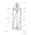
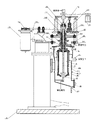
まず、被処理液の遠心分離時における竪型遠心分離装置1の基本動作について説明する。図1の状態では、コイルばね54の付勢力により羽根部6全体が相対的に上方に位置しており、ボウル5と羽根部6とが契合状態にある。この状態から、第1のシリンダ241が下降するように不図示のアクチュエータを駆動する。かかる動作により、羽根駆動用モータ73が下方に移動し、羽根駆動用モータ73の駆動軸と羽根部6の回転軸62とが結合される。次に、第2のシリンダ242が下降するように不図示のアクチュエータを駆動する。かかる動作により、ボウル5内の下部のテーパー部511と結合状態にある各ウィング612がコイルばね54のばね力に抗して下方に移動し、羽根部6の下部がボウル5より解放され、羽根部6とボウル5との結合が解除される。
次に、ボウル5内の洗浄時における手順及び竪型遠心分離装置1の動作等について説明する。まず、排出時に取り外した供給管42付きのカバー部材41を、ケーシング4に取り付ける。次に、リフター211が図1の位置から上昇するように不図示のアクチュエータを駆動する。かかる動作により、リフター211と共に上昇した低速駆動用モータ72の駆動軸が、本体駆動用モータ71の下部側の駆動軸に契合して連結される。
さらに、定期的なメインテナンス等のため、或いは被処理液の種類によっては、最終的にはボウル5や羽根部6をケーシング4から取り外して分解、洗浄等することが必要となる。以下に、図5を参照して、回転筒の分解作業時における手順及び竪型遠心分離装置1の動作等について説明する。
続いて、本発明の第2の実施形態について、添付図面を参照しながら詳しく説明する。なお、本実施形態は、装置のコンパクト化を図るために好適な構造としたこと、及び封水洗浄が可能な構造としたことを除けば第1の実施形態と同様の構造を有する。従って、本実施形態の竪型遠心分離装置1も、第1の実施形態と同様に、約2万Gの遠心力を得る高速回転を安定して行うことができ、遠心分離された固形物の排出及び洗浄を効率良く行うことができる構造である。
4 ケーシング
4A 上ケーシング
4B 下ケーシング
5 ボウル
511 テーパー部(契合部)
53 インデックスリング(第1のリング状部材)
533,534,535 突起部
54 コイルばね(付勢手段)
6 羽根部(排出部材)
612 ウィング
613 テーパー部(契合部)
616 横噴射ノズル
617 縦噴射ノズル
63 インナーリング(第2のリング状部材)
71 本体駆動用モータ
72 低速駆動用モータ
73 羽根駆動用モータ
8 ボールベアリング
81 グリス注入孔
82 間座
821 グリス貯留空間
Claims (12)
- ケーシングと、
前記ケーシングに回転可能に収容された回転筒状体であり、内部に供給された被処理液を遠心力の作用により液体と固形物とに分離し、分離された液体と固形物をそれぞれの排出口から排出するためのボウルと、
前記ボウル内に回転可能に収容され、分離された固形物をボウル内から排出するための排出部材と、
を有し、
前記ボウル及び前記排出部材は、軸方向への相対移動により契合/契合解除する契合部と、前記ボウルと前記排出部材との一体回転時における動バランスを考慮した位置になるように、前記排出部材と前記ボウルとの位相を回転軸周りの少なくとも一箇所で位置合わせする位置合わせ機構と、を備え、被処理液の遠心分離時には前記位置合わせ機構による位相を保持した契合状態で一体に回転し、該契合状態の解除により相対回転可能となることを特徴とする竪型遠心分離装置。 - 前記ボウルと前記排出部材は、被処理液の遠心分離時に略2万Gの遠心力を伴って一体に高速回転することを特徴とする請求項1記載の竪型遠心分離装置。
- 前記ボウル及び前記排出部材は、軸方向の一方側が回転可能に軸支され、他方側が自由端とされた片持ち支持構造であることを特徴とする請求項1又は2に記載の竪型遠心分離装置。
- 前記ボウルは、略円筒形の槽状を呈し被処理液が供給されるボウル本体と、該ボウル本体の上部に一体に設けられた中空の回転軸と、を備え、
前記排出部材は、複数のウィングが一体形成され前記ボウル本体内に収容される羽根部本体と、該羽根部本体から上方に突出し、前記ボウルの中空の回転軸内に回転可能に設けられる回転軸と、を備え、
前記契合部は、前記ボウル及び前記排出部材の下部側に設けられ、前記ボウルの内径及び前記羽根部本体のそれぞれの幅が下方になるに従ってテーパー状に広がるテーパー部を有し、前記排出部材が前記ボウルに対して上方に相対移動すると、前記ボウルの回転駆動時に前記排出部材が一体に回転する契合状態となる
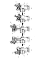
ことを特徴とする請求項3記載の竪型遠心分離装置。 - 前記位置合わせ機構は、前記ボウルの回転軸に設けられた第1のリング状部材と、前記排出部材の回転軸に設けられ前記第1のリング状部材に対峙する第2のリング状部材とを有し、一方のリング状部材に溝部が形成され、他方のリング状部材には前記溝部に嵌合される突起部が形成されたことを特徴とする請求項4記載の竪型遠心分離装置。
- 前記溝部及び突起部は、各々複数設けられ、前記各回転軸を相対回転させると、前記突起部の各々が対応する前記溝部の各々に対して嵌合される位置に配置されており、且つ、
前記溝部及び突起部の各々は、前記回転軸の軸中心からなす角度が不等角になる位置に配置されたことを特徴とする請求項5記載の竪型遠心分離装置。 - 前記排出部材を一方向に付勢する付勢手段を有し、前記契合部は、前記位置合わせ機構による位置合わせ完了時に、前記付勢手段の付勢により前記ボウルと排出部材とを契合状態にすることを特徴とする請求項1乃至6のいずれか記載の竪型遠心分離装置。
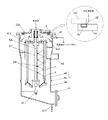
- 前記ボウルの軸受機構が、軸方向に配列された複数のボールベアリングと、各々のボールベアリングに形成されている潤滑用グリスの注入孔と、潤滑用グリスを注入することによってボールベアリングから排出される余剰のグリスを貯留する空間が形成された間座と、を備えていることを特徴とする請求項1乃至7のいずれか記載の竪型遠心分離装置。
- 前記ケーシング内でボウル及び排出部材を封水洗浄するために、ケーシング内に洗浄液を供給するノズルと、ケーシングを気密にするためのシール機構と、をさらに備え、
前記シール機構が、ケーシングの連結部に配置され、その内部に加圧用の流体が付勢供給されると膨張してシール特性が向上するシール部材と、このシール部材に前記流体を供給する手段と、を含むことを特徴とする請求項1乃至8のいずれか記載の竪型遠心分離装置。 - 前記排出部材は、前記ボウルの内部に収容される部位に設けられた中空軸と、該中空軸に連通するように設けられた噴射ノズルと、
を有し、前記中空軸の一端側から付勢供給された洗浄液を前記噴射ノズルから外方に噴射することで前記排出部材及びボウル内部を洗浄する洗浄機構を備えたことを特徴とする請求項1乃至9のいずれか記載の竪型遠心分離装置。 - 前記噴射ノズルは、前記付勢供給された洗浄液を前記排出部材に向けて噴出するとともに、排出部材から反射された洗浄液が前記ボウルの内壁に当たる位置に配置された
ことを特徴とする請求項10記載の竪型遠心分離装置。 - 前記ケーシングと一体をなす固定フレームと、
該固定フレームに対して上下移動可能に設けられる上下動フレームと、
前記ボウルが取付けられるとともに、前記排出部材が着脱可能に取付けられ、前記上下動フレームに対して回動可能に設けられる回動フレームと、を備え、
前記上下動フレームが上昇させられることにより、前記ボウル及び前記排出部材が前記ケーシングから引き抜かれ、
前記回動フレームの回動後に前記上下動フレームが下降させられることにより、前記排出部材を前記回動フレームから離脱させるための分解機構を備えた
ことを特徴とする請求項1乃至11のいずれか記載の竪型遠心分離装置。
Priority Applications (1)
| Application Number | Priority Date | Filing Date | Title |
|---|---|---|---|
| JP2010547451A JP5512552B2 (ja) | 2009-01-26 | 2010-01-26 | 竪型遠心分離装置 |
Applications Claiming Priority (4)
| Application Number | Priority Date | Filing Date | Title |
|---|---|---|---|
| JP2009014305 | 2009-01-26 | ||
| JP2009014305 | 2009-01-26 | ||
| PCT/JP2010/000418 WO2010084782A1 (ja) | 2009-01-26 | 2010-01-26 | 竪型遠心分離装置 |
| JP2010547451A JP5512552B2 (ja) | 2009-01-26 | 2010-01-26 | 竪型遠心分離装置 |
Publications (2)
| Publication Number | Publication Date |
|---|---|
| JPWO2010084782A1 JPWO2010084782A1 (ja) | 2012-07-19 |
| JP5512552B2 true JP5512552B2 (ja) | 2014-06-04 |
Family
ID=42355837
Family Applications (1)
| Application Number | Title | Priority Date | Filing Date |
|---|---|---|---|
| JP2010547451A Active JP5512552B2 (ja) | 2009-01-26 | 2010-01-26 | 竪型遠心分離装置 |
Country Status (4)
| Country | Link |
|---|---|
| US (1) | US9005097B2 (ja) |
| JP (1) | JP5512552B2 (ja) |
| CA (1) | CA2750286A1 (ja) |
| WO (1) | WO2010084782A1 (ja) |
Families Citing this family (20)
| Publication number | Priority date | Publication date | Assignee | Title |
|---|---|---|---|---|
| JP5571919B2 (ja) * | 2009-07-31 | 2014-08-13 | 巴工業株式会社 | 竪型遠心分離装置及び遠心分離液の回収方法 |
| JP2014151276A (ja) * | 2013-02-08 | 2014-08-25 | Flowserve Japan Co Ltd | 立型固液分離機 |
| JP6040311B2 (ja) * | 2013-06-14 | 2016-12-07 | 巴工業株式会社 | 遠心分離装置 |
| JP5475919B1 (ja) * | 2013-11-01 | 2014-04-16 | 巴工業株式会社 | 密閉タイプのデカンタ型遠心分離機 |
| JP6023369B1 (ja) * | 2016-02-22 | 2016-11-09 | 巴工業株式会社 | 遠心分離装置 |
| EP3257587B1 (en) | 2016-06-14 | 2018-12-26 | Alfa Laval Corporate AB | Centrifugal separator with dismountable bowl-hood |
| CN107008577A (zh) * | 2017-06-09 | 2017-08-04 | 大连隆田科技有限公司 | 一种具有自动清洗功能的立式螺旋液固离心机 |
| US10814338B2 (en) | 2017-08-09 | 2020-10-27 | Delta Separations, Llc | Device, system and methods for separation and purification of organic compounds from botanical material |
| US12303917B2 (en) * | 2017-10-19 | 2025-05-20 | Adalberto Mercado Alvarado | Substance separator system driven by a submersible actuator |
| CN109248792B (zh) * | 2018-11-01 | 2024-03-08 | 象山蓝越食品机械制造有限公司 | 脱水机 |
| CN109985733B (zh) * | 2019-05-10 | 2024-02-23 | 辽宁贝克瑞生物科技有限公司 | 一种管式离心机 |
| CN111054528B (zh) * | 2019-12-12 | 2024-02-02 | 武汉德泽环保科技有限公司 | 一种活塞推料离心机及其送料方法 |
| CN112661286B (zh) * | 2020-12-23 | 2024-03-29 | 马佳婷 | 一种节能环保的污水快速离心渗析处理机构 |
| WO2022155136A1 (en) * | 2021-01-12 | 2022-07-21 | The Regents Of The University Of Colorado, A Body Corporate | Continuous centrifugal isolating system and methods of use thereof |
| CN114889843B (zh) * | 2022-05-17 | 2024-06-07 | 中国工程物理研究院总体工程研究所 | 一种离心机轴向与切向过载输出高精度测算方法 |
| CN116673130B (zh) * | 2023-08-02 | 2023-10-17 | 山东芝圣堂生物科技有限公司 | 一种提取孢子油的离心机 |
| CN117548244B (zh) * | 2024-01-11 | 2024-04-09 | 江苏赛德力制药机械制造有限公司 | 一种应用在离心机上的残余滤饼刮除结构 |
| EP4667111A1 (en) * | 2024-06-17 | 2025-12-24 | Alfa Laval Corporate AB | A centrifugal separator |
| CN120394207B (zh) * | 2025-07-03 | 2025-09-12 | 江西天奇金泰阁钴业有限公司 | 一种三元前驱体料浆离心固液分离装置 |
| CN120502442B (zh) * | 2025-07-22 | 2025-11-18 | 福建常青新能源科技有限公司 | 一种富锂锰三元材料前驱体洗涤装置 |
Citations (6)
| Publication number | Priority date | Publication date | Assignee | Title |
|---|---|---|---|---|
| JPS5318060A (en) * | 1976-08-02 | 1978-02-18 | Neos Kk | Centrifugal separator |
| JPS55153147U (ja) * | 1979-04-19 | 1980-11-05 | ||
| JPH08131894A (ja) * | 1994-11-15 | 1996-05-28 | Trinity Ind Corp | スラッジ回収装置 |
| JP2005066711A (ja) * | 2003-08-25 | 2005-03-17 | Yutaka Seimitsu Kogyo Ltd | 切削液・切粉分離装置 |
| JP2005522321A (ja) * | 2002-04-12 | 2005-07-28 | ワグナー デベロップメント インコーポレイテッド | スクレーパー又はピストンを用いて固形物類を排出する遠心機 |
| JP2007190493A (ja) * | 2006-01-19 | 2007-08-02 | Nagano Seisakusho:Kk | スラッジ回収装置 |
Family Cites Families (8)
| Publication number | Priority date | Publication date | Assignee | Title |
|---|---|---|---|---|
| JPS55153147A (en) | 1979-05-18 | 1980-11-28 | Matsushita Electric Ind Co Ltd | Tape recorder |
| EP0056511A3 (en) * | 1981-01-19 | 1984-07-11 | The Chartwell House Group Limited | Improved centrifuge and method of cleaning a centrifuge drum |
| US5743840A (en) * | 1996-06-24 | 1998-04-28 | Carr Separations, Inc. | Centrifuge with a heating jacket for drying collected solids |
| US5908376A (en) * | 1997-09-11 | 1999-06-01 | Costner Industries Nevada, Inc. | Self-cleaning rotor for a centrifugal separator |
| US6126587A (en) * | 1998-04-08 | 2000-10-03 | U.S. Centrifuge | Centrifugal separator apparatus including a plow blade assembly |
| DE10314118B4 (de) * | 2003-03-28 | 2005-05-12 | Westfalia Separator Ag | Antriebsvorrichtung für einen Separator |
| US7396324B2 (en) * | 2003-10-17 | 2008-07-08 | Hitachi Koki Co., Ltd. | Centrifugal separator with first and second control panels |
| WO2007086114A1 (ja) | 2006-01-25 | 2007-08-02 | Tomoe Engineering Co., Ltd. | 竪型遠心分離機 |
-
2010
- 2010-01-26 WO PCT/JP2010/000418 patent/WO2010084782A1/ja not_active Ceased
- 2010-01-26 US US13/146,077 patent/US9005097B2/en not_active Expired - Fee Related
- 2010-01-26 JP JP2010547451A patent/JP5512552B2/ja active Active
- 2010-01-26 CA CA2750286A patent/CA2750286A1/en not_active Abandoned
Patent Citations (6)
| Publication number | Priority date | Publication date | Assignee | Title |
|---|---|---|---|---|
| JPS5318060A (en) * | 1976-08-02 | 1978-02-18 | Neos Kk | Centrifugal separator |
| JPS55153147U (ja) * | 1979-04-19 | 1980-11-05 | ||
| JPH08131894A (ja) * | 1994-11-15 | 1996-05-28 | Trinity Ind Corp | スラッジ回収装置 |
| JP2005522321A (ja) * | 2002-04-12 | 2005-07-28 | ワグナー デベロップメント インコーポレイテッド | スクレーパー又はピストンを用いて固形物類を排出する遠心機 |
| JP2005066711A (ja) * | 2003-08-25 | 2005-03-17 | Yutaka Seimitsu Kogyo Ltd | 切削液・切粉分離装置 |
| JP2007190493A (ja) * | 2006-01-19 | 2007-08-02 | Nagano Seisakusho:Kk | スラッジ回収装置 |
Also Published As
| Publication number | Publication date |
|---|---|
| US9005097B2 (en) | 2015-04-14 |
| US20110301013A1 (en) | 2011-12-08 |
| JPWO2010084782A1 (ja) | 2012-07-19 |
| CA2750286A1 (en) | 2010-07-26 |
| WO2010084782A1 (ja) | 2010-07-29 |
Similar Documents
| Publication | Publication Date | Title |
|---|---|---|
| JP5512552B2 (ja) | 竪型遠心分離装置 | |
| US10573507B2 (en) | Substrate processing apparatus and substrate processing method | |
| US9484230B2 (en) | Substrate liquid processing apparatus | |
| KR20160025770A (ko) | 표면처리부품의 탈루장치 | |
| JP6279954B2 (ja) | 基板処理装置 | |
| KR20180011732A (ko) | 기판 처리 장치 | |
| DK3065876T3 (en) | CLEANING DEVICE WITH ROTATING PRELET BREAD AND REPLACEABLE PATTERN DRIVE | |
| CN110813552B (zh) | 一种平板沉降式全自动离心机 | |
| US9421582B1 (en) | Pivoting centrifugal parts cleaner | |
| JPH0347574B2 (ja) | ||
| WO2016019876A1 (zh) | 滚筒洗衣机 | |
| CN1706567A (zh) | 清洗装置及包含该装置的阀门设备 | |
| JP6280789B2 (ja) | 基板処理装置および基板処理方法 | |
| JP6040311B2 (ja) | 遠心分離装置 | |
| CN101198413A (zh) | 改进的避免交叉污染的离心机 | |
| JP2009082808A (ja) | 遠心分離機 | |
| JP6107173B2 (ja) | 遠心機用ロータおよび遠心機 | |
| KR200284275Y1 (ko) | 원심 비중분리형 정제장치 | |
| CN117612932B (zh) | 晶圆清洗方法及清洗装置 | |
| CN222279790U (zh) | 一种悬臂式双轴测试转台结构 | |
| JP2005132383A (ja) | 容器処理装置及び洗浄装置 | |
| JP5308291B2 (ja) | 基板洗浄装置 | |
| JP4383424B2 (ja) | デカンタ型遠心分離機及びその洗浄方法 | |
| JP2009106940A (ja) | 遠心分離機 | |
| JP6023369B1 (ja) | 遠心分離装置 |
Legal Events
| Date | Code | Title | Description |
|---|---|---|---|
| A621 | Written request for application examination |
Free format text: JAPANESE INTERMEDIATE CODE: A621 Effective date: 20121220 |
|
| A131 | Notification of reasons for refusal |
Free format text: JAPANESE INTERMEDIATE CODE: A131 Effective date: 20131022 |
|
| RD03 | Notification of appointment of power of attorney |
Free format text: JAPANESE INTERMEDIATE CODE: A7423 Effective date: 20131125 |
|
| A521 | Request for written amendment filed |
Free format text: JAPANESE INTERMEDIATE CODE: A523 Effective date: 20131217 |
|
| TRDD | Decision of grant or rejection written | ||
| A01 | Written decision to grant a patent or to grant a registration (utility model) |
Free format text: JAPANESE INTERMEDIATE CODE: A01 Effective date: 20140325 |
|
| A61 | First payment of annual fees (during grant procedure) |
Free format text: JAPANESE INTERMEDIATE CODE: A61 Effective date: 20140326 |
|
| R150 | Certificate of patent or registration of utility model |
Ref document number: 5512552 Country of ref document: JP Free format text: JAPANESE INTERMEDIATE CODE: R150 |
|
| R250 | Receipt of annual fees |
Free format text: JAPANESE INTERMEDIATE CODE: R250 |
|
| R250 | Receipt of annual fees |
Free format text: JAPANESE INTERMEDIATE CODE: R250 |
|
| R250 | Receipt of annual fees |
Free format text: JAPANESE INTERMEDIATE CODE: R250 |
|
| R250 | Receipt of annual fees |
Free format text: JAPANESE INTERMEDIATE CODE: R250 |
|
| R250 | Receipt of annual fees |
Free format text: JAPANESE INTERMEDIATE CODE: R250 |
|
| R250 | Receipt of annual fees |
Free format text: JAPANESE INTERMEDIATE CODE: R250 |
|
| R250 | Receipt of annual fees |
Free format text: JAPANESE INTERMEDIATE CODE: R250 |