JP5512552B2 - Vertical centrifuge - Google Patents
Vertical centrifuge Download PDFInfo
- Publication number
- JP5512552B2 JP5512552B2 JP2010547451A JP2010547451A JP5512552B2 JP 5512552 B2 JP5512552 B2 JP 5512552B2 JP 2010547451 A JP2010547451 A JP 2010547451A JP 2010547451 A JP2010547451 A JP 2010547451A JP 5512552 B2 JP5512552 B2 JP 5512552B2
- Authority
- JP
- Japan
- Prior art keywords
- bowl
- casing
- discharge member
- liquid
- vertical
- Prior art date
- Legal status (The legal status is an assumption and is not a legal conclusion. Google has not performed a legal analysis and makes no representation as to the accuracy of the status listed.)
- Active
Links
Images


Classifications
-
- B—PERFORMING OPERATIONS; TRANSPORTING
- B04—CENTRIFUGAL APPARATUS OR MACHINES FOR CARRYING-OUT PHYSICAL OR CHEMICAL PROCESSES
- B04B—CENTRIFUGES
- B04B1/00—Centrifuges with rotary bowls provided with solid jackets for separating predominantly liquid mixtures with or without solid particles
- B04B1/02—Centrifuges with rotary bowls provided with solid jackets for separating predominantly liquid mixtures with or without solid particles without inserted separating walls
-
- B—PERFORMING OPERATIONS; TRANSPORTING
- B04—CENTRIFUGAL APPARATUS OR MACHINES FOR CARRYING-OUT PHYSICAL OR CHEMICAL PROCESSES
- B04B—CENTRIFUGES
- B04B11/00—Feeding, charging, or discharging bowls
- B04B11/04—Periodical feeding or discharging; Control arrangements therefor
- B04B11/05—Base discharge
-
- B—PERFORMING OPERATIONS; TRANSPORTING
- B04—CENTRIFUGAL APPARATUS OR MACHINES FOR CARRYING-OUT PHYSICAL OR CHEMICAL PROCESSES
- B04B—CENTRIFUGES
- B04B11/00—Feeding, charging, or discharging bowls
- B04B11/08—Skimmers or scrapers for discharging ; Regulating thereof
-
- B—PERFORMING OPERATIONS; TRANSPORTING
- B04—CENTRIFUGAL APPARATUS OR MACHINES FOR CARRYING-OUT PHYSICAL OR CHEMICAL PROCESSES
- B04B—CENTRIFUGES
- B04B15/00—Other accessories for centrifuges
- B04B15/06—Other accessories for centrifuges for cleaning bowls, filters, sieves, inserts, or the like
-
- B—PERFORMING OPERATIONS; TRANSPORTING
- B04—CENTRIFUGAL APPARATUS OR MACHINES FOR CARRYING-OUT PHYSICAL OR CHEMICAL PROCESSES
- B04B—CENTRIFUGES
- B04B7/00—Elements of centrifuges
- B04B7/02—Casings; Lids
-
- B—PERFORMING OPERATIONS; TRANSPORTING
- B04—CENTRIFUGAL APPARATUS OR MACHINES FOR CARRYING-OUT PHYSICAL OR CHEMICAL PROCESSES
- B04B—CENTRIFUGES
- B04B9/00—Drives specially designed for centrifuges; Arrangement or disposition of transmission gearing; Suspending or balancing rotary bowls
- B04B9/12—Suspending rotary bowls ; Bearings; Packings for bearings
-
- B—PERFORMING OPERATIONS; TRANSPORTING
- B04—CENTRIFUGAL APPARATUS OR MACHINES FOR CARRYING-OUT PHYSICAL OR CHEMICAL PROCESSES
- B04B—CENTRIFUGES
- B04B11/00—Feeding, charging, or discharging bowls
- B04B11/08—Skimmers or scrapers for discharging ; Regulating thereof
- B04B2011/086—Skimmers or scrapers for discharging ; Regulating thereof with a plurality of scraper blades
Landscapes
- Centrifugal Separators (AREA)
Description
本発明は、種々の被処理液を遠心分離するために用いられる遠心分離装置に関し、特に、遠心分離動作時に発生した固形物を自動で排出する機構を備えた竪型の遠心分離装置に関する。 The present invention relates to a centrifuge used for centrifuging various liquids to be treated, and more particularly to a vertical centrifuge having a mechanism for automatically discharging solid matter generated during a centrifuge operation.
一般に、竪型の遠心分離装置は、ケーシングと、該ケーシング内に回転可能に格納されるボウルと、ボウルを駆動するモータ等の駆動部と、を有しており、前記ボウルが前記ケーシングの上下両方側に設けられたベアリング等の軸受けにより支持される構造のものが知られている(例えば、特許文献1参照)。かかる竪型遠心分離装置は、さらに、ケーシングの上方側に重液を排出するための重液排出部が、該重液排出部の上方に軽液を排出するための軽液排出部が設けられ、遠心分離動作時には被処理液がボウル内に供給された状態でボウルが高速回転し(例えば毎分1万回転以上)、強大な遠心力(例えば2万G)が発生することにより、被処理液から分離された重液及び軽液が各排出部から排出される構造となっている。 In general, a vertical centrifuge includes a casing, a bowl that is rotatably stored in the casing, and a drive unit such as a motor that drives the bowl. A structure that is supported by bearings such as bearings provided on both sides is known (see, for example, Patent Document 1). The vertical centrifugal separator is further provided with a heavy liquid discharge part for discharging heavy liquid above the casing, and a light liquid discharge part for discharging light liquid above the heavy liquid discharge part. During the centrifugal separation, the bowl is rotated at a high speed (for example, 10,000 revolutions per minute or more) while the liquid to be treated is supplied into the bowl, and a strong centrifugal force (for example, 20,000 G) is generated. The heavy liquid and the light liquid separated from the liquid are discharged from each discharge portion.
上述した従来の竪型遠心分離装置では、遠心分離動作時に発生した固形物を自動で排出する機構が設けられていなかったため、ボウル内に溜まった固形物を取り出すために、被処理液の遠心分離の終了時にボウルをケーシングから取り外す必要等が生じ、時間及び手間を要していた。 In the conventional vertical centrifuge described above, a mechanism for automatically discharging the solid matter generated during the centrifugation operation is not provided. Therefore, in order to take out the solid matter accumulated in the bowl, the liquid to be treated is centrifuged. At the end of the process, it was necessary to remove the bowl from the casing, which required time and labor.
特に、被処理液として食品や化学薬品などが対象となる場合には、かかる被処理液の遠心分離後に、ボウル内を可能な限り清潔に洗浄することが必要となる。この点、上述した従来の竪型遠心分離装置では、洗浄時にはボウルを本体から取り外して洗浄を行っていたため、固形物がボウル内に残存した状態から洗浄を行う必要があり、洗浄完了までに時間及びコストがかかっていた。 In particular, when food, chemicals, or the like is a target liquid to be processed, it is necessary to clean the inside of the bowl as cleanly as possible after centrifugation of the liquid to be processed. In this regard, in the conventional vertical centrifuge described above, since the bowl is removed from the main body at the time of cleaning, it is necessary to perform the cleaning from the state in which the solid matter remains in the bowl. And it was costly.
このような状況に鑑みて、発生した固形物の自動排出を実現するために、固形物をボウル外に排出するための排出部材をボウル内に設け、ボウルと排出部材とを相対的に回転できるようにする構造が、本発明者らの開発過程で提案された。さらに、本発明者らの開発過程では、ボウルの容量(径)増大を図りつつ、固形物の自動排出を迅速、円滑に行う等のために、ボウル及び排出部材を含む回転体をケーシングの一方側(例えば上方側)のみで回転可能に支持する、いわゆる片持ち支持とする構造が提案された。 In view of such a situation, in order to realize automatic discharge of the generated solid matter, a discharge member for discharging the solid matter outside the bowl is provided in the bowl, and the bowl and the discharge member can be rotated relatively. A structure to do so was proposed in the development process of the present inventors. Further, in the development process of the present inventors, in order to increase the capacity (diameter) of the bowl and to automatically and smoothly discharge the solid matter, the rotating body including the bowl and the discharging member is placed on one side of the casing. There has been proposed a so-called cantilevered structure that is supported rotatably only on the side (for example, the upper side).
しかしながら、このように回転体を片側のみで支持し駆動する構造とする場合には、高速回転させる際のボウル及び排出部材の動バランスが重要となり、かかるバランスが崩れると振動、故障等の原因になる。このため、回転体を高速回転させる際に、ボウルと排出部材との回転軸周りにおける相対位置(位相)を、動バランスが最も良好となる位置に合わせておく必要があり、かつ、各種作業やメインテナンス等の後にも、当該位置への位置合わせを繰り返し再現できるようにする必要がある。 However, in the case of a structure in which the rotating body is supported and driven only on one side as described above, the dynamic balance of the bowl and the discharge member when rotating at high speed is important, and if this balance is lost, vibration, failure, etc. may occur. Become. For this reason, when rotating the rotating body at a high speed, it is necessary to match the relative position (phase) of the bowl and the discharge member around the rotation axis to the position where the dynamic balance is the best, and various operations and Even after maintenance or the like, it is necessary to repeat the alignment at the position.
さらにまた、メインテナンスや内部のさらなる洗浄作業等のため、最終的にはボウル等を本体から取り外して分解できることが必要となるが、かかる分解作業における簡易迅速性を実現できる構造が求められる。 Furthermore, for maintenance and further internal cleaning work, it is necessary that the bowl and the like can be finally removed from the main body and can be disassembled. However, a structure capable of realizing simple and rapid in such disassembly work is required.
本発明は、上述した課題を解決するために提案されたものであり、その第1の目的は、遠心分離処理時に発生した固形物を、該処理後に自動で排出する機構を備えた竪型遠心分離装置を提供することにある。 The present invention has been proposed in order to solve the above-described problems, and a first object of the present invention is a vertical centrifuge equipped with a mechanism for automatically discharging solid matter generated during centrifugation after the treatment. It is to provide a separation device.
本発明の第2の目的は、高速回転させる際のボウル及び羽根部の動バランスを考慮した機構を備えた竪型遠心分離装置を提供することにある。 A second object of the present invention is to provide a vertical centrifuge having a mechanism that takes into account the dynamic balance of the bowl and blades when rotating at high speed.
本発明の第3の目的は、被処理液の遠心分離後に、ボウルを本体から取り外すことなく自動で洗浄を行う機構を備えた竪型遠心分離装置を提供することにある。 A third object of the present invention is to provide a vertical centrifuge equipped with a mechanism for automatically washing without removing a bowl from a main body after centrifugation of a liquid to be treated.
本発明の第4の目的は、分解作業における簡易迅速性を実現した構造を備えた竪型遠心分離装置を提供することにある。 A fourth object of the present invention is to provide a vertical centrifuge having a structure that realizes simple and quickness in the disassembling work.
上記課題を解決するために、本発明の竪型遠心分離装置の主たる構成は、ケーシングと、前記ケーシングに回転可能に収容された回転筒状体であり、内部に供給された被処理液を遠心力の作用により液体と固形物とに分離し、分離された液体と固形物をそれぞれの排出口から排出するためのボウルと、前記ボウル内に回転可能に収容され、分離された固形物をボウル内から排出するための排出部材と、を有し、前記ボウル及び前記排出部材は、軸方向への相対移動により契合/契合解除する契合部と、前記ボウルと前記排出部材との一体回転時における動バランスを考慮した位置になるように、前記排出部材と前記ボウルとの位相を回転軸周りの少なくとも一箇所で位置合わせする位置合わせ機構と、を備え、被処理液の遠心分離時には前記位置合わせ機構による位相を保持した契合状態で一体に回転し、該契合状態の解除により相対回転可能となることを特徴とする。
In order to solve the above problems, the main configuration of the vertical centrifuge of the present invention is a casing and a rotating cylindrical body rotatably accommodated in the casing, and the liquid to be treated supplied therein is centrifuged. A bowl for separating the liquid and solids by the action of force, and discharging the separated liquid and solids from the respective discharge ports, and the separated solid contained in the bowl so as to be rotatable. A discharge member for discharging from the inside, and the bowl and the discharge member are an engagement portion that engages / cancels engagement by relative movement in the axial direction, and the bowl and the discharge member at the time of integral rotation so that the position in consideration of the dynamic balance, and a positioning mechanism for aligning at least one portion around the rotation axis the phase of the bowl and the discharge member, said during centrifugation the liquid to be treated Rotate together with engaged while holding the phase by location setting mechanism, characterized in that the relatively rotatable by releasing the 該契 engaged state.
かかる構成において、ボウルと排出部材は、被処理液の遠心分離時に略2万Gの遠心力を伴って一体に高速回転する。 In such a configuration, the bowl and the discharge member rotate together at high speed with a centrifugal force of approximately 20,000 G when the liquid to be treated is centrifuged.
また、ボウルは、略円筒形の槽状を呈し被処理液が供給されるボウル本体と、該ボウル本体の上部に一体に設けられた中空の回転軸と、を備え、排出部材は、複数のウィングが一体形成されボウル本体内に収容される羽根部本体と、該羽根部本体から上方に突出し、ボウルの中空の回転軸内に回転可能に設けられる回転軸と、を備え、契合部は、ボウル及び排出部材の下部側に設けられ、ボウルの内径及び羽根部本体のそれぞれの幅が下方になるに従ってテーパー状に広がるテーパー部を有し、排出部材がボウルに対して上方に相対移動すると、ボウルの回転駆動時に排出部材が一体に回転する契合状態となる構成とすることができる。 The bowl has a substantially cylindrical tank shape and is provided with a bowl main body to which the liquid to be treated is supplied, and a hollow rotary shaft integrally provided on the upper portion of the bowl main body. A wing part body formed integrally with the wing and accommodated in the bowl body; and a rotating shaft that protrudes upward from the wing part body and is rotatably provided in the hollow rotating shaft of the bowl. Provided on the lower side of the bowl and the discharge member, and having a tapered portion that expands in a tapered shape as the inner diameter of the bowl and the width of each of the blade portion main bodies are lowered, and when the discharge member moves relative to the bowl upward, It can be set as the structure which will be in the engagement state which a discharge member rotates integrally at the time of the rotational drive of a bowl.
また、位置合わせ機構は、ボウルの回転軸に設けられた第1のリング状部材と、排出部材の回転軸に設けられ第1のリング状部材に対峙する第2のリング状部材とを有し、一方のリング状部材に溝部が形成され、他方のリング状部材には溝部に嵌合される突起部が形成された構成とすることができる。 The alignment mechanism includes a first ring-shaped member provided on the rotating shaft of the bowl, and a second ring-shaped member provided on the rotating shaft of the discharge member and facing the first ring-shaped member. The groove portion is formed in one of the ring-shaped members, and the projection portion that is fitted into the groove portion is formed in the other ring-shaped member.
好ましくは、溝部及び突起部は、各々複数設けられ、各回転軸を相対回転させると、突起部の各々が対応する前記溝部の各々に対して嵌合される位置に配置されるようにする。これを実現するため、例えば、溝部及び突起部の各々は、回転軸の軸中心からなす角度が不等角になる位置に配置される。 Preferably, a plurality of grooves and protrusions are provided, and when the respective rotation shafts are rotated relative to each other, each of the protrusions is arranged at a position where it is fitted to each of the corresponding grooves. In order to realize this, for example, each of the groove portion and the protrusion portion is disposed at a position where the angle formed from the axis center of the rotation shaft becomes an unequal angle.
さらに、竪型遠心分離装置では、排出部材を一方向に付勢する付勢手段を有し、契合部は、位置合わせ機構による位置合わせ完了時に、付勢手段の付勢によりボウルと排出部材とを契合状態にする構成とすることが好ましい。 Furthermore, the vertical centrifuge has a biasing means for biasing the discharge member in one direction, and the engagement portion is configured to move the bowl and the discharge member by biasing of the biasing means when the alignment by the alignment mechanism is completed. It is preferable to set it as the structure made into an agreement state.
前記竪型遠心分離装置は、遠心分離時にボウルを高速回転させることが可能なように、ボウルの軸受機構が、軸方向に配列された複数のボールベアリングと、各々のボールベアリングに形成されている潤滑用グリスの注入孔と、潤滑用グリスを注入することによってボールベアリングから排出される余剰のグリスを貯留する空間が形成された間座と、を備えていることが好ましい。 In the vertical centrifuge, the bowl bearing mechanism is formed on a plurality of ball bearings arranged in the axial direction and each ball bearing so that the bowl can be rotated at high speed during centrifugation. It is preferable to include an injection hole for lubricating grease and a spacer formed with a space for storing excess grease discharged from the ball bearing by injecting the lubricating grease.
また、前記ケーシング内でボウル及び排出部材を封水洗浄するために、ケーシング内に洗浄液を供給するノズルと、ケーシングを気密にするためのシール機構と、をさらに備え、前記シール機構が、ケーシングの連結部に配置され、その内部に加圧用の流体が付勢供給されると膨張してシール特性が向上するシール部材と、このシール部材に前記流体を供給する手段と、を含む構造であることが好ましい。 Further, in order to seal and wash the bowl and the discharge member in the casing, the nozzle further supplies a cleaning liquid into the casing, and a sealing mechanism for making the casing airtight, and the sealing mechanism includes a casing. A structure including a seal member that is disposed in the connecting portion and expands when a pressurizing fluid is urged and supplied to the inside thereof, and means for supplying the fluid to the seal member. Is preferred.
さらに、竪型遠心分離装置の排出部材は、ボウルの内部に収容される部位に設けられた中空軸と、該中空軸に連通するように設けられた噴射ノズルと、を有し、中空軸の一端側から付勢供給された洗浄液を前記噴射ノズルから外方に噴射することで前記排出部材及びボウル内部を洗浄する洗浄機構を備えた構成とすることができる。ここで、噴射ノズルは、前記付勢供給された洗浄液を前記排出部材に向けて噴出するとともに、排出部材から反射された洗浄液が前記ボウルの内壁に当たる位置に配置されることが好ましい。前記封水洗浄するための洗浄水は、前記噴射ノズルから供給するようにしてもよい。 Further, the discharge member of the vertical centrifuge has a hollow shaft provided in a portion accommodated in the bowl, and an injection nozzle provided so as to communicate with the hollow shaft. A cleaning mechanism that cleans the discharge member and the inside of the bowl by spraying the cleaning liquid biased and supplied from one end side outward from the spray nozzle can be provided. Here, it is preferable that the spray nozzle is disposed at a position where the cleaning liquid supplied with biasing force is ejected toward the discharge member and the cleaning liquid reflected from the discharge member hits the inner wall of the bowl. You may make it supply the washing water for the said sealing water washing | cleaning from the said injection nozzle.
さらにまた、本発明の竪型遠心分離装置は、ケーシングと一体をなす固定フレームと、該固定フレームに対して上下移動可能に設けられる上下動フレームと、ボウルが取付けられるとともに、排出部材が着脱可能に取付けられ、上下動フレームに対して回動可能に設けられる回動フレームと、を備え、上下動フレームが上昇させられることにより、ボウル及び排出部材がケーシングから引き抜かれ、回動フレームの回動後に上下動フレームが下降させられることにより、排出部材を回動フレームから離脱させるための分解機構を備えることができる。 Furthermore, the vertical centrifuge of the present invention has a fixed frame integrated with the casing, a vertically moving frame provided so as to be movable up and down with respect to the fixed frame, a bowl is attached, and a discharge member is detachable. And a pivot frame provided so as to be pivotable with respect to the vertical motion frame. When the vertical motion frame is raised, the bowl and the discharge member are pulled out from the casing, and the pivot frame rotates. By subsequently lowering the vertically moving frame, a disassembling mechanism for detaching the discharge member from the rotating frame can be provided.
本発明の竪型遠心分離装置によれば、被処理液の遠心分離の終了時にボウルと排出部材との契合状態が解除され、ボウルに対して排出部材が相対回転することにより、遠心分離動作時に発生した固形物を自動で排出することが可能となる。また、本発明によれば、排出部材と前記ボウルとの位相を回転軸周りの例えば一箇所で位置合わせするための位置合わせ機構を備え、被処理液の遠心分離時には位置合わせ機構による位相を保持した契合状態で一体に回転し、該契合状態の解除により相対回転可能となるので、駆動時、或いはメインテナンス後の再取付けの際などに、ボウル及び排出部材を、高速回転時における動バランスを保つための一定の位置に再現することが可能となる。その結果、例えば2万Gの遠心力を得るために高速回転させることが可能となり、さらに振動等が抑えられ、その回転動作が安定している。 According to the vertical centrifuge of the present invention, the engagement state between the bowl and the discharge member is released at the end of the centrifugation of the liquid to be processed, and the discharge member rotates relative to the bowl, so that the centrifugal operation is performed. The generated solid matter can be automatically discharged. In addition, according to the present invention, there is provided an alignment mechanism for aligning the phase of the discharge member and the bowl at, for example, one place around the rotation axis, and the phase by the alignment mechanism is maintained when the liquid to be treated is centrifuged. Rotate integrally in the engaged state, and can be rotated relative to each other by releasing the engaged state, so that the dynamic balance of the bowl and the discharge member during high-speed rotation is maintained during driving or when reattaching after maintenance. Therefore, it can be reproduced at a certain position. As a result, for example, it is possible to rotate at a high speed in order to obtain a centrifugal force of 20,000 G, and further, vibration and the like are suppressed, and the rotation operation is stable.
また、本発明の洗浄機構を有する竪型遠心分離装置によれば、被処理液の遠心分離後に、ボウル内を自動で洗浄することが可能になる。ここで、噴射ノズルの位置を、付勢供給された洗浄液を排出部材に向けて噴出するとともに、排出部材から反射された洗浄液がボウルの内壁に当たる位置とすることにより、排出部材とボウルとを一度に洗浄することが可能となる。 Moreover, according to the vertical centrifuge having the cleaning mechanism of the present invention, the inside of the bowl can be automatically cleaned after the liquid to be processed is centrifuged. Here, the position of the spray nozzle is set so that the cleaning liquid supplied with biasing force is ejected toward the discharge member, and the cleaning liquid reflected from the discharge member hits the inner wall of the bowl. It becomes possible to wash it.
さらに、本発明の分解構造を有する竪型遠心分離装置によれば、固定フレームとケーシングとが一体をなし、固定フレームに対して上下移動する上下動フレームを備えるとともに、上下動フレームに対して回動フレームが回動可能に設けられ、さらに回動フレームにボウルが回動可能に設けられるので、上下動フレームの上昇により回動フレーム及びボウルが一体に上昇して、ボウルをケーシングの上方に引き抜くことが可能になり、さらに回動フレームの回動により、ケーシングの上方に位置するボウルをケーシングから離隔することが可能になる。 Furthermore, according to the vertical centrifugal separator having the disassembly structure of the present invention, the fixed frame and the casing are integrated, and the vertical frame is provided to move up and down relative to the fixed frame. Since the moving frame is pivotably provided, and the bowl is pivotally provided on the pivoting frame, the pivoting frame and the bowl are integrally lifted by the raising of the vertically moving frame, and the bowl is pulled out above the casing. Further, the bowl positioned above the casing can be separated from the casing by the rotation of the rotating frame.
(第1の実施形態)
本発明の第1の実施形態を、図面を参照しながら詳細に説明する。(First embodiment)
A first embodiment of the present invention will be described in detail with reference to the drawings.
図1に示すように、本実施形態の竪型遠心分離装置1は、基台(床面)11上に載置されたフレーム2に対して竪型の遠心分離機本体3が取付けられた構造を有している。
As shown in FIG. 1, the vertical centrifuge 1 of the present embodiment has a structure in which a vertical centrifuge
ここで、フレーム2は、基台11上に載置、固着され、遠心分離機本体3のケーシング4が固定される固定フレーム21と、この固定フレーム21に対して移動可能とされた可動フレーム22と、を備える。可動フレーム22は、固定フレーム21に対して昇降すなわち上下移動可能に設けられた上下動フレーム23と、上下動フレーム23に対して回動可能に設けられた回動フレーム24と、を備える。
Here, the
固定フレーム21は、略角柱状を呈した中空の構造であり、その内部に上下動フレーム23を上下移動可能に収容する。上下動フレーム23は、その下部が柱状を呈し、固定フレーム21の内部に設けられた後述する昇降機構により、固定フレーム21内の空間部を上下移動する。上下動フレーム23の上部は、平面略円形を呈し、回動フレーム24を回動可能に支持する支持部(図示せず)を介して回動フレーム24と接続される。
The fixed
回動フレーム24は、その一端側が後述する遠心分離機本体3のケーシング4の上部に着脱可能に接続され、他端側には本体駆動用モータ71が配置される。また、回動フレーム24の略中央部すなわち重心位置近傍の部分が平面略円形を呈し、上述した固定フレーム21の支持部に対して回動可能に接続される接続部となっている。
One end side of the
回動フレーム24の一端側には、さらに、羽根駆動用モータ73を回動フレーム24に対して上/下方向に移動させるための第1のシリンダ241と、第1のシリンダ241の下部に連結して配置され、後述する排出部材としての羽根部6の位置を上/下方向に移動させるための第2のシリンダ242と、後述するボウル5の回転軸52の上部に当接してボウル5の回転を停止させるためのブレーキ243と、が設けられる。これらシリンダ241,242及びブレーキ243は、それぞれ不図示のアクチュエータにより駆動される。
One end of the
また、フレーム2には駆動手段としての複数のモータが設けられる。本実施形態では、被処理液の遠心分離時に動作される本体駆動用モータ71と、遠心分離機本体3の洗浄時に動作される低速駆動用モータ72と、後述するボウル5と羽根部6との位置決めの際、及び遠心分離時に発生した固形物の排出動作の際に駆動される羽根駆動用モータ73と、遠心分離機本体3の分解作業時に駆動されるボウル取出し用モータ74と、の4つが設けられる。
The
このうち、本体駆動用モータ71は、回動フレーム24に取付けられ、その駆動軸がモータ本体の上方及び下方の両端から突出される。この本体駆動用モータ71は、上側の駆動軸にプーリ710が取付けられ、このプーリ710に掛け渡された駆動ベルト711を介して駆動力をボウル5に伝達する。また、本体駆動用モータ71の下側の駆動軸は、低速駆動用モータ72の駆動軸に対峙し、かつその先端部が低速駆動用モータ72の駆動軸の先端側と契合する形状を有する。
Among these, the main
低速駆動用モータ72は、その駆動軸が本体駆動用モータ71の駆動軸と同軸上に位置するように、本体駆動用モータ71の下方の固定フレーム21に取付けられる。低速駆動用モータ72の駆動軸は、その先端部が本体駆動用モータ71の駆動軸の先端部と契合する形状を有する。そして、低速駆動用モータ72は、固定フレーム21の側面を上下移動するリフター211に取付けられており、リフター211が不図示のアクチュエータにより図1の状態から上方向に移動することによって、低速駆動用モータ72の駆動軸の先端が本体駆動用モータ71の駆動軸の先端と嵌合し両駆動軸が結合される。この結合状態において低速駆動用モータ72が回転駆動されると、その駆動力が、本体駆動用モータ71の駆動軸及び駆動ベルト711等を介してボウル5に伝達される。
The low-
羽根駆動用モータ73は、その駆動軸が後述する羽根部6の回転軸62と同軸上に位置するように、上述した第1のシリンダ241及び第2のシリンダ242を介して回動フレーム24の上方に取付けられる。ここで、羽根駆動用モータ73の駆動軸は、羽根部6の回転軸62の上端に対峙し、軸の先端が羽根部6の回転軸62の上端側と契合する形状を有する。
The
ボウル取出し用モータ74は、固定フレーム21の内部に設けられた昇降機構の回転軸212に駆動チェーン741を介して駆動力を伝達するものであり、その駆動軸が下向きになるように固定フレーム21の下部に配置され、該駆動軸には駆動チェーン741を架け渡すためのスプロケット740が設けられる。
The bowl take-out
ここで、上下動フレーム23を昇降すなわち上下移動させるための昇降機構について説明する。昇降機構は、回転軸212と、回転軸212に取付けられた上下動フレーム23の下部の突出部231と、回転軸212を回転駆動するボウル取出し用モータ74と、を備えて構成される。
Here, an elevating mechanism for moving the up and down moving
回転軸212は、略円柱状の部材であり、固定フレーム21の内部の上下に沿って配置され、不図示のベアリング等によって固定フレーム21の内部に回転可能に支持される。この回転軸212は、表面に不図示のねじ溝が形成されており、駆動チェーン741を介してボウル取出し用モータ74によって回転駆動される。一方、上下動フレーム23の突出部231にも回転軸212のねじ溝に螺合する不図示のねじ孔が形成されており、かかる突出部231が回転軸212に組み付けられる。したがって、ボウル取出し用モータ74で回転軸212を正/逆方向に回転駆動することにより、回転軸212に取付けられた突出部231と一体をなす上下動フレーム23が上/下方向に移動する。
The
遠心分離機本体3は、固定フレーム21と一体に接続された略円筒形のケーシング4と、このケーシング4内に回転可能に格納されるボウル5と、該ボウル5内に回転可能に格納されボウル5内の固形物を排出するための排出部材としての羽根部6と、を有する。
The
ケーシング4は、全体略円筒状の外形をなし、底部側が絞り込まれた形状とされることで、内部が容器(槽)状とされる。このケーシング4は、側面の一端側が固定フレーム21に不図示の締結ボルト等によって連結され、側面の他端側には後述する重液排出部43が設けられる。さらに、ケーシング4の上端側に、オーバーフロー用の排出ノズル44が設けられている。この排出ノズル44は、例えばケーシング4内を封水洗浄する場合に、洗浄液をオーバーフローさせるために使用することができる。
The
ケーシング4の下部には、着脱可能な平面略円形のカバー部材41が取付けられ、このカバー部材41の中央に、被処理液と洗浄液を供給するための供給管42が配置される。また、供給管42の近傍には、後述する洗浄時における洗浄液及びボウル5内のゴミ等(被処理液の残存物など)を排出するための排液口411が設けられる。さらに、ケーシング4の上部側には、被処理液の遠心分離時に分離発生される重液を排出するための重液排出部43が、ケーシング4外部に突出するように設けられる。
A detachable planar substantially
ケーシング4の上面部には、回動フレーム24の一端側が着脱可能に配置される。すなわち、回動フレーム24の一端側は、ケーシング4の上部を覆うための蓋部244が形成されている。この蓋部244は、その外径がボウル5の外径よりも大径の略円板状を呈している。また、この蓋部244には、被処理液の遠心分離時に分離発生される軽液を排出するための軽液排出部25が、ボウル5の上方と連通するように設けられる。本実施形態では、ケーシング4が固定フレーム21に固定され、回動フレーム24は上下動フレーム23の昇降に伴って一体に上下動することから、回動フレーム24が上方に移動すると、ボウル5及び羽根部6が上方に移動してケーシング4から引き抜かれる。
One end side of the
ボウル5は、被処理液が供給されるボウル本体51と、ボウル本体51の上部に一体に設けられ、回動フレーム24に回転可能に支持される回転軸52と、を備える。
The
ボウル本体51は、ケーシング4よりも小型の略円筒形の槽状を呈し、その底部には蓋部材510が不図示のボルト等の固定手段により着脱可能に取付けられる。この蓋部材510は、平面略円環状を呈し、その中央には、上述した供給管42が挿入されるとともに、ボウル5内の固形物(ケーキ)を排出するための略円形の穴部510aが形成される。そして、蓋部材510は、その機能の一つとしてボウル5内の固形物(ケーキ)の排出を容易にするために、図2に示すように、穴部510a側に向かって傾斜する断面形状を有している。一方、ボウル5の上部には、ボウル本体51を回転駆動するための回転軸52が一体に設けられる。ボウル5の回転軸52は、回動フレーム24の一端側にベアリング等の軸受機構521を介して回転可能に支持される。また、ボウル5の回転軸52の中心部には、羽根部6を回転可能に支持するために、中空の回転支持部520が形成される。
The bowl
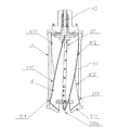
図2及び図3に示すように、羽根部6は、回転中心となる軸部材611から複数の板状のウィング612が突出形成された構造の羽根部本体61と、軸部材611と同軸上に設けられ羽根部本体61から上方に突出する回転軸62と、を備える。本実施形態では、4枚の相互に同形状のウィング612が隣接ウィング相互間で90度の角度をなすように設けられ、各ウィングの各々の外側が、平面時計方向にねじれた形状を呈している。羽根部6は、その回転軸62が上述したボウル5の回転軸52における回転支持部520に挿入されることで、羽根部6全体がボウル5及び回動フレーム24に対して回転可能に支持される。
As shown in FIGS. 2 and 3, the
羽根部6の各ウィング612は、ボウル5の内部でボウル5と相対回転可能とするために、ボウル5の内径よりも若干小径の外形を有している。また、本実施形態では、羽根部6とボウル5とを結合状態にして一体で回転可能にするために、羽根部6及びボウル5の下部側に契合部が形成される。以下、この契合部の詳細について説明する。
Each
竪型遠心分離装置1において、ボウル5及び羽根部6は、軸方向すなわち上下方向への相対移動により契合/契合解除する契合部を備えている。本実施形態では、図2及び図3に示すように、ボウル5の内壁の下部に、端部側すなわち下方に進むほど内径が大きくなる形状のテーパー部511が設けられる。一方、羽根部6は、4つのウィング612の各々の外側の下部に、端部側すなわち下方に進むほどウィング612の外径の幅が大きくなる形状のテーパー部613が形成される。ここで、各ウィング612のテーパー部613は、ボウル5のテーパー部511の形状と略一致する形状となっている。より詳細には、各ウィング612の各々の外側の下部の外形は、羽根部本体61が最下方に位置するときにはボウル5のテーパー部511よりも若干小径であり、したがってボウル5の内壁に干渉することがない。一方、羽根部6が上方に移動すると、各ウィング612のテーパー部613がボウル5のテーパー部511に当接することにより、各ウィング612がボウル5の内壁に契合し、ボウル5と羽根部6とが一時的に結合された状態となる。かかる契合部を備えた竪型遠心分離装置1では、羽根部6が上方に引き上げられることによりボウル5及び羽根部6が契合し、被処理液の遠心分離動作時において、両部材(5,6)が固定され、一体で高速回転可能な状態となる。
In the vertical centrifuge 1, the
次に、図3を参照して、ボウル5内を洗浄するための構成について説明する。図3に示すように、供給管42は、相対的に細い中央の洗浄液供給管421の外側(周囲)に、被処理液供給管422が配置された二重管構造になっており、被処理液は外側の被処理液供給口422a及び被処理液移動空間422bを通じて被処理液噴出口422cから、洗浄液は内側(中央)の洗浄液供給口421a及び洗浄液移動空間421bを通じて洗浄液噴出口421cから、それぞれ供給、噴出されるようになっている。
Next, a configuration for cleaning the inside of the
一方、羽根部6の軸部材611には、洗浄液を通過させるための内部管614が設けられる。この内部管614は、羽根部本体61における軸部材611の下部一端側から上部側まで形成される。ここで、内部管614が連通される軸部材611の下部一端側は、供給管42の洗浄液噴出口421cに接続又は近接配置されており、洗浄液噴出口421cの外形形状に対応する凹陥した形状を呈する接続部611aとなっている。また、図3に示すように、羽根部6の各ウィング612は、供給管42の先端部と干渉しないように、接続部611aの近傍が略「L」字状に切り欠かれた形状となっている。
On the other hand, the
さらに、羽根部6の羽根部本体61では、この内部管614と連通するように複数のノズル615が軸部材611上に配置される。ここで、ノズル615は、洗浄液を横方向すなわちウィング612の外側に向けてハイインパクトで噴出するための横噴射ノズル616と、洗浄液を縦方向すなわちウィング612の上側/下側に向けてハイインパクトで噴出するための縦噴射ノズル617とが、各々の洗浄液噴射方向が各ウィングの片面に向けられるように設けられる。ここで、横噴射ノズル616及び縦噴射ノズル617の各々は、噴出口が扁平状を呈しており、供給された洗浄液を平面状に広げるような態様で噴出するようになっている。
Furthermore, in the blade portion
横噴射ノズル616は、羽根部本体61の軸部材611上に所定間隔で多数個(1枚のウイングに対して例えば6個)配置される。また、横噴射ノズル616のそれぞれは、図3(a)に示すように、噴出された洗浄液が相互に若干重なるような間隔で配置されるのが好ましい。一方、縦噴射ノズル617は、羽根部本体61の軸部材611上に、ウィングの上側と下側とに向けて1個ずつ(1枚のウィングに対して例えば2個)配置される。縦噴射ノズル617は、被処理液の噴出方向が横噴出ノズル616のそれぞれの洗浄液の噴出方向と干渉しないような位置に配置される。
A large number of
本実施形態では、横噴射ノズル616と縦噴射ノズル617とが、1枚のウィングに対してそれぞれ1列ずつ軸部材611上に設けられる。すなわち、本実施形態では、ウィング612を4枚備えた構造であるため、横噴射ノズル616及び縦噴射ノズル617は、それぞれ4列づつ(合計で32個)配置される。
In the present embodiment, the
ここで、供給管42に被処理液が供給されると、かかる被処理液は、図3(b)に示すように接続部611aの斜面によって外側に広がるように噴出され、ボウル5内に供給される。一方、洗浄時に、供給管42に洗浄液が所定の圧力にて付勢供給されると、かかる洗浄液は、図3(a)に示すように羽根部6の軸部材611の内部管614の一端側から上昇し、かかる内部管614に連通された各ノズル616,617から外部にハイインパクトで噴出される。このとき、各ノズル616,617から噴出された洗浄液は、ウィング612の外縁に近い部位に所定角度にて強い勢いで当たり、かつ、ウィング612から反射されてボウル5の内壁に当たる。
Here, when the liquid to be processed is supplied to the
なお、横噴射ノズル616及び縦噴射ノズル617のノズル種類や数は特に限定されるものではなく、各ノズルにおける洗浄液の噴出方向(広がる角度)やウィングのサイズ等に応じて適宜変更することができる。また、必ずしも横噴射ノズル616と縦噴射ノズル617の両方を備えていなくともよい。
The type and number of the
さらに、竪型遠心分離装置1では、羽根部6とボウル5とを回転軸周りの所定の位相、例えば回転軸周りの一箇所で位置合わせするための位置合わせ機構が設けられている。かかる位置合わせ機構は、羽根部6及びボウル5の各回転軸62,52の上方側に、複数の溝部及び該溝部に嵌合される複数の突起部が形成され、各回転軸62,52を相対回転させると、前記嵌合部の各々が対応する前記溝部の各々に対して嵌合されることによって、回転軸周りの一箇所に位置合わせされる構造となっている。以下、この位置合わせ機構について図4を参照して説明する。
Further, the vertical centrifuge 1 is provided with an alignment mechanism for aligning the
本実施形態では、位置合わせ機構は、ボウル5の回転軸52の上端に固着されたインデックスリング53と、羽根部6側に設けられインデックスリング53と契合するインナーリング63と、を備え、インデックスリング53側に突起部が、インナーリング63側に溝部が形成される。
In the present embodiment, the alignment mechanism includes an
インデックスリング53は、平面略円環状をなし、その中央には羽根部6の回転軸62が挿入されるための平面円形の孔部531が形成され、外側にはインナーリング63の側面が挿入されるための平面リング状の立上り壁部532が形成される。そして、図4(a)に示すように、インデックスリング53の立上り壁部532の内側に沿って、複数(この実施形態では3箇所)の突起部533,534,535が設けられる。ここで、各突起部の中央部が回転軸62の軸中心からなす角度(θ1,θ2,θ3)は、相互に異なる角度、例えば100°、120°、及び140°の不等角となっている。
The
一方、羽根部6の回転軸62の上端近傍には、インデックスリング53と契合するインナーリング63が回転軸62に対して着脱可能に取付けられる。このインナーリング63は、その外径がインデックスリング53の内径よりも若干小さい平面略円環状をなし、中央には羽根部6の回転軸62が嵌入されるための平面略円形の孔部631が形成される。この孔部631には、羽根部6の回転軸62に設けられた位置合わせ用の凸部(図示せず)が嵌入されるための切欠部631aが設けられる。また、インナーリング63は、先端側にフランジ部632が形成されることで、インデックスリング53に対峙する下側の部位が外側に張り出された形状となっている。そして、インナーリング63のフランジ部632には、インデックスリング53の各突起部533,534,535に対応する数(この実施形態では3個)の溝部633,634,635が、上記各突起部に対応する位置に形成される。すなわち、各溝部633,634,635の中央部が回転軸62の軸中心からなす角度は、各突起部533,534,535に対応した不等角の角度、すなわち本例では100°、120°、及び140°となっている。
On the other hand, an
さらに、インデックスリング53とインナーリング63との間には、インナーリング63ひいては羽根部6全体を上方に付勢する付勢手段としてのコイルばね54が、羽根部6の回転軸62に挿入されるように配置される。
Further, between the
かかる構成を備えた本実施形態では、コイルばね54のばね力に逆らってインナーリング63をインデックスリング53の方向に押し付ける力を加えながら、羽根部6の回転軸62を中心としてインナーリング63とインデックスリング53とを相対回動させた場合に、インデックスリング53の突起部533,534,535が、インナーリング63の溝部633,634,635にそれぞれ嵌入されることにより、ボウル5側のインデックスリング53と羽根部6側のインナーリング63とが契合し、これによりボウル5と羽根部6とが回転軸62周りの一箇所のみに位置合わせされる。
In the present embodiment having such a configuration, the
したがって、この竪型遠心分離装置1では、遠心分離の動作時、或いはメインテナンス後の各部の再取付けの際などに、ボウル5と羽根部6との回転軸周りにおける相対位置を、高速回転時における動バランスを保つための一定の位置に再現することが可能となる。すなわち、本実施形態のように、遠心分離時にはボウル5と羽根部6を一体に回転させ、その後のケーキ排出時及び洗浄時に相対回転させる構成とした場合、相対回転を停止したときの回転軸周りのボウル5と羽根部6の位置関係が、一体回転させたときの位置に戻っているとは限らない。高速回転を行う場合、例えば製作誤差に起因する僅かなアンバランスによっても振動が生じ、安定した高速回転を行えない場合がある。従って、例えば振動が最も小さくなる位相を試験等を行って把握し、一体に回転させるときには毎回この位相で位置決めされるようにすることにより、動バランスを考慮した位置決めを具現化する。そして、インデックスリング53とインナーリング63との間に両部材を付勢するばねを介在させた構成となっているので、インナーリング63をインデックスリング53の方向に押し付ける力が解除されることで、ボウル5と羽根部6との回転軸周りにおける一定の位置を保持しながら、上述したボウル5及び羽根部6の内部に設けられた契合部でボウル5及び羽根部6を契合させ、位置決めされた位相を維持することが可能になる。
Therefore, in the vertical centrifuge 1, the relative position of the
本発明において、位置合わせ機構は、羽根部6とボウル5との回転軸周りの相対位置を、最も動バランスが良好となる一箇所のみで位置決めできる構成であればよい。しかし、必ずしも一箇所である必要はなく、動バランスが許容される範囲内であれば複数の個所で位置決めされる構成としてもよい。また、例えば、本実施形態では、ボウル5側に突起部を備えたリング状部材を設け、この突起部に嵌合される溝部を備えたリング状部材を羽根部6側に設ける構成としたが、この逆すなわちボウル5側に溝部を設け、該溝部に嵌合される突起部を羽根部6側に設ける構成とすることもできる。
In the present invention, the alignment mechanism may be configured so that the relative position of the
また、本実施形態では、溝部及び突起部の数を3個ずつとしたが、かかる数も特に限定されるものではない。但し、羽根部6とボウル5との回転軸周りの相対位置を一箇所のみで位置決めできるようにするために、溝部及び突起部の数が複数個の場合には、上述のように、隣接する溝部同士及び突起部同士の回転軸から成す角度を相互に異なる角度(不等角)に設定することが好ましい。なお、隣接する溝部同士及び突起部同士のそれぞれの角度を等角度で配置する場合、例えば溝部及び突起部の数が3つの場合で軸中心から相互に120°の角度で配置されるような場合には、各溝部及び突起部の回転軸からの位置(位相)が相互に異なる距離になるように配置する構成とすることで、同様の効果を得ることができる。
Moreover, in this embodiment, although the number of the groove parts and the protrusion parts was set to three, such numbers are not particularly limited. However, in order to be able to position the relative position of the
以下、竪型遠心分離装置1の各動作を説明する。 Hereinafter, each operation of the vertical centrifuge 1 will be described.
(遠心分離時)
まず、被処理液の遠心分離時における竪型遠心分離装置1の基本動作について説明する。図1の状態では、コイルばね54の付勢力により羽根部6全体が相対的に上方に位置しており、ボウル5と羽根部6とが契合状態にある。この状態から、第1のシリンダ241が下降するように不図示のアクチュエータを駆動する。かかる動作により、羽根駆動用モータ73が下方に移動し、羽根駆動用モータ73の駆動軸と羽根部6の回転軸62とが結合される。次に、第2のシリンダ242が下降するように不図示のアクチュエータを駆動する。かかる動作により、ボウル5内の下部のテーパー部511と結合状態にある各ウィング612がコイルばね54のばね力に抗して下方に移動し、羽根部6の下部がボウル5より解放され、羽根部6とボウル5との結合が解除される。(When centrifuging)
First, the basic operation of the vertical centrifuge 1 when centrifuging the liquid to be treated will be described. In the state of FIG. 1, the
続いて、ブレーキ243がONすなわちボウル5の回転軸52に当接するように不図示のアクチュエータを駆動する。かかる動作により、ボウル5が回動フレーム24及びケーシング4に対して固定された状態となる。かかるボウル5の固定状態から、羽根駆動用モータ73を駆動することで、羽根部6全体が回転する。このとき、上述した位置合わせ機構におけるインナーリング63の溝部633,634,635にインデックスリング53の突起部533,534,535が嵌入され、インナーリング63とインデックスリング53とが所定の位置で契合することで、羽根部6とボウル5との軸周りの位置(位相)が、動バランスを考慮した高速回転可能な位置にセットされる。
Subsequently, an actuator (not shown) is driven so that the
次に、第1のシリンダ241及び第2のシリンダ242が上昇するように不図示のアクチュエータを駆動する。かかる動作により、コイルばね54の付勢力により羽根部6全体が上方に移動し、ボウル5のテーパー部511及び羽根部6のテーパー部613同士が当接、契合して羽根部6とボウル5とが固定される。このとき、インナーリング63がインデックスリング53から離れるが、上述した位置合わせ機構でセットされた高速回転可能な位置にて、羽根部6のテーパー部613がボウル5のテーパー部511に契合し、ボウル5と羽根部6とが一体で回転可能な状態になる。
Next, an actuator (not shown) is driven so that the
続いて、この状態から本体駆動用モータ71を駆動するとともに、所定の回転数を達成してから供給管42からボウル5内に被処理液を供給する。かかる動作により、羽根部6とボウル5とが一体で高速回転され、供給された被処理液の固−液分離作業が開始される。以下、ボウル5及び羽根部6を総称して「回転筒状体」と呼ぶ。かかる高速回転時には、回転筒状体は、その回転数及び遠心力が約10000rpm/20000G(2万G)となるが、上述のように、ボウル5と羽根部6との位相が動バランスを考慮した位置の状態で一体回転する。このため、本実施形態の竪型遠心分離装置1では、回転筒状体の回転速度が高速になるほど、いわゆる回転の芯が出てくるようになり、片持ち支持の構造でありながら、遠心分離時に発生する振動を少なく抑えることが可能になる。さらには、本実施形態の竪型遠心分離装置1によれば、遠心分離時に発生する振動を上下両方の軸受けで吸収していた従来の両持ち支持の構造の竪型遠心分離装置と比較して、ボウルの径を相対的に大径にすることも可能になる。
Subsequently, the main
しかして、かかる竪型遠心分離装置1によれば、被処理液の遠心分離時には、極めて大きな遠心力の作用により、分離された軽液が最上方の軽液排出部25から、重液がその下方の重液排出部43からそれぞれ排出され、さらに、分離された固形物(ケーキ)が回転筒状体内に溜まる。
Thus, according to the vertical centrifugal separator 1, when the liquid to be treated is centrifuged, the separated light liquid is removed from the uppermost light
そして、回転筒内に固形物が一定量(例えば40リットル程度)溜まったら、被処理液の供給を停止し、本体駆動用モータ71の駆動を停止させることで回転筒状体の回転が停止し、これにより固−液分離作業が終了する。
When a certain amount (for example, about 40 liters) of solid matter is accumulated in the rotating cylinder, the supply of the liquid to be processed is stopped and the driving of the main
以下、回転筒内に溜まった固形物の排出時の動作等について説明する。上述した回転筒の停止状態から、第1のシリンダ241が下降するように不図示のアクチュエータを駆動する。かかる動作により、羽根駆動用モータ73の駆動軸と羽根部6の回転軸62とが結合される。
Hereinafter, the operation | movement at the time of discharge | emission of the solid substance which accumulated in the rotation cylinder is demonstrated. An actuator (not shown) is driven so that the
さらに、第2のシリンダ242が下降するように不図示のアクチュエータを駆動することにより、羽根部6が下降してボウル5からウィング612を解放し、ボウル5と羽根部6との契合状態が解除される。
Further, by driving an actuator (not shown) so that the
続いて、供給管42付きのカバー部材41をケーシング4から取り外す。これにより、回転筒状体内に溜まった固形物を開口となった穴部510aから排出することが可能となる。
Subsequently, the
次に、ブレーキ243がONすなわちボウル5の回転軸52に当接するように不図示のアクチュエータを駆動する。かかる動作により、ボウル5が回動フレーム24及びケーシング4に対して固定された状態となる。かかるボウル5の固定状態から、羽根駆動用モータ73を駆動することで、羽根部6のみが所定方向(本実施形態では平面反時計方向)に回転する。これにより、ボウル5内に溜まった固形物が羽根部6の各ウィング612により掻き出されて、ボウル本体51の穴部510aから外部に排出される。排出された固形物は、さらに、カバー部材41が取り外されたケーシング4の下側から外部に落下する。
Next, an actuator (not shown) is driven so that the
したがって、本実施形態の竪型遠心分離装置1によれば、遠心分離処理時に発生しボウル5内に溜まった固形物につき、ボウル5をケーシング4から取り外すことなく自動で排出することが可能となる。なお、固形物(ケーキ)の粘性が高く羽根駆動用モータ73のトルクが過剰となったりする場合には、羽根部6を回転させる前か回転と共に洗浄液を噴射ノズル616,617から噴出することによって、固形物の排出を促進させることが可能である。また、目的物が分離液である場合にも、同様に洗浄液を噴出して固形物の排出を促進させるようにしてもよい。
Therefore, according to the vertical centrifuge 1 of the present embodiment, it is possible to automatically discharge the solid matter generated in the centrifugation process and accumulated in the
すなわち、竪型遠心分離装置1の上述した動作により、ボウル5内から固形物が完全にないし可及的に除去された状態になるので、この後に行われるボウル5内の洗浄に要する時間やコスト等が大幅に削減される。具体的には、ボウル5をケーシング4から取り外す必要がなくなり、また、被処理液の種類やメインテナンス等によりボウル5をケーシング4から取り外してボウル5内のさらなる洗浄を行う場合であっても、洗浄完了までの時間及びコストが大幅に削減される。したがって、例えば被処理液として食品や化学薬品を扱う場合の洗浄完了までの時間及びコストが、従来の竪型遠心分離装置と比較して大幅に縮減される。
That is, the above-described operation of the vertical centrifugal separator 1 causes the solids to be removed completely or as much as possible from the inside of the
(洗浄時)
次に、ボウル5内の洗浄時における手順及び竪型遠心分離装置1の動作等について説明する。まず、排出時に取り外した供給管42付きのカバー部材41を、ケーシング4に取り付ける。次に、リフター211が図1の位置から上昇するように不図示のアクチュエータを駆動する。かかる動作により、リフター211と共に上昇した低速駆動用モータ72の駆動軸が、本体駆動用モータ71の下部側の駆動軸に契合して連結される。(When washing)
Next, the procedure at the time of cleaning the inside of the
続いて、供給管42に洗浄液を付勢供給しながら、ボウル5を低速駆動用モータ72で低速回転させることでボウル5内の洗浄を行う。このとき、羽根部6の回転を停止させ、ブレーキ243はOFF(解放)にしておき、ボウル5のみ回転させるようにする。かかる動作により、洗浄液が羽根部6の各ノズル616,617からハイインパクトで出射され、該出射された洗浄液が強い勢いでウィング612に当たり、さらにはウィング612に当たった洗浄液が反射してボウル5内面に当たることにより、回転筒状体内が自動で洗浄される。このとき、上述した固形物の自動排出時に除去しきれなかったもの、特に、ウィング612やボウル5内壁に付着したまま残存した固形物が、付勢供給される洗浄液の物理的及び化学的作用により良好に落とされ、洗浄液とともにボウル5内から速やかに除去され、排液口411からケーシング4の外部に排出される。
Subsequently, while the cleaning liquid is energized and supplied to the
かかる洗浄機構を備えた本実施形態の竪型遠心分離装置1では、従来の封水方式、すなわちボウル内に洗浄液を供給し封止状態でボウルを回転することでボウル内を洗浄していた方式の竪型遠心分離装置と比較して、ボウル内の洗浄に要する時間が大幅に短縮される。具体的には、従来の封水方式の竪型遠心分離装置では洗浄完了までに30分程度要していたが、本実施形態によれば5分程度でボウル内の洗浄を完了することが可能になる。 In the vertical centrifuge 1 of this embodiment provided with such a cleaning mechanism, a conventional sealing method, that is, a method in which the bowl is cleaned by supplying a cleaning liquid into the bowl and rotating the bowl in a sealed state. Compared with the vertical centrifuge, the time required for cleaning the bowl is greatly reduced. Specifically, the conventional sealed-type vertical centrifuge requires about 30 minutes to complete the cleaning, but according to the present embodiment, the cleaning of the bowl can be completed in about 5 minutes. become.
かかる洗浄運転の終了の後に、リフター211が下降するように不図示のアクチュエータを駆動することで、低速駆動用モータ72の駆動軸と本体駆動用モータ71の下部側の駆動軸との連結が解除される。
After the end of the cleaning operation, the actuator (not shown) is driven so that the
(分解時)
さらに、定期的なメインテナンス等のため、或いは被処理液の種類によっては、最終的にはボウル5や羽根部6をケーシング4から取り外して分解、洗浄等することが必要となる。以下に、図5を参照して、回転筒の分解作業時における手順及び竪型遠心分離装置1の動作等について説明する。(When disassembling)
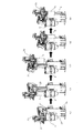
Furthermore, for periodic maintenance or the like, or depending on the type of the liquid to be treated, it is necessary to finally remove the
まず、図5(a)の状態から、ボウル取出し用モータ74が所定方向に駆動されることにより、上述した昇降機構の回転軸212が回転して上下動フレーム23及び回動フレーム24が一体に上昇する。かかる動作により、図5(b)に示すように、回動フレーム24に取付けられたボウル5及び羽根部6からなる回転筒が上昇し、ケーシング4から上方に引き抜かれる。
First, from the state of FIG. 5A, when the bowl take-out
次に、図5(b)の状態から、回動フレーム24が上下動フレーム23に対して所定角度、この実施形態では平面反時計方向に90度回動されるように、不図示のアクチュエータを駆動する。かかる動作により、図5(c)に示すように、ケーシング4の上方に位置する回転筒がケーシング4から離隔され、回転筒の下方にはケーシング4及びその他の部材が存しない状態となる。
Next, from the state of FIG. 5 (b), an actuator (not shown) is turned so that the
続いて、図5(c)の状態から、ボウル取出し用モータ74が前述の上昇時とは反対方向に駆動されることで、上下動フレーム23及び回動フレーム24が一体に下降し、図5(d)に示すように、回転筒の上部がケーシング4の高さ位置と一致する。そして、図5(d)の状態から、ボウル本体51から蓋部510が取り外され、羽根部6の回転軸62からインナーリング63が取り外された後に、図5(e)に示すように、羽根部6が下方に抜き出される。したがって、この後、羽根部6及びボウル5の内壁を洗浄することが可能になる。
Subsequently, from the state of FIG. 5 (c), the
このように、本実施形態の竪型遠心分離装置1では、固定フレーム21とケーシング4とが一体をなし、固定フレーム21に対して上下動フレーム23が昇降可能に設けられるとともに、上下動フレーム23に対して回動フレーム24が回動可能に設けられ、さらに回動フレーム24にボウル5が回動可能に設けられた構成を備え、上下動フレーム23の上昇により回動フレーム24及びボウル5が一体に上昇して、ボウル5をケーシング4の上方に引き抜くことが可能になり、さらに回動フレーム24の回動により、ケーシング4の上方に位置するボウル5をケーシング4から離隔することが可能になるので、回転筒の分解作業を簡易迅速に行うことが可能となる。
As described above, in the vertical centrifugal separator 1 of the present embodiment, the fixed
上述した実施形態では、ボウル5内を洗浄するための洗浄機構として、ノズル615(横噴射ノズル616及び縦噴射ノズル617)を、1枚のウィング612の片面に向けて洗浄液を噴出するように配置した構成について説明したが、他の実施形態として、ノズル615(横噴射ノズル616及び/又は縦噴射ノズル617)を、1枚のウィング612の両面(表面及び裏面の両方)に向けて洗浄液を噴出するように配置した構成とすることができる。この場合には、例えば図3(a)に示す6個の横噴射ノズル616の各々の間に、隣接するウィングを洗浄するための他の横噴射ノズル616を設ける構成とすることができる。かかる構成とすることにより、ボウル内の洗浄に要する時間の一層の短縮を図ることが可能になる。図6は、羽根部本体61の他の一例を示している。すなわち、図6に示す羽根部本体61は、3枚のウィング612が軸部材611から突出形成された構造であり、さらに1枚のウィング612の両面(表面及び裏面の両方)に向けて洗浄液を噴出するように交互に向きを変えた横噴射ノズル616を配置している。
In the embodiment described above, as a cleaning mechanism for cleaning the inside of the
(第2実施形態)
続いて、本発明の第2の実施形態について、添付図面を参照しながら詳しく説明する。なお、本実施形態は、装置のコンパクト化を図るために好適な構造としたこと、及び封水洗浄が可能な構造としたことを除けば第1の実施形態と同様の構造を有する。従って、本実施形態の竪型遠心分離装置1も、第1の実施形態と同様に、約2万Gの遠心力を得る高速回転を安定して行うことができ、遠心分離された固形物の排出及び洗浄を効率良く行うことができる構造である。(Second Embodiment)
Next, a second embodiment of the present invention will be described in detail with reference to the attached drawings. The present embodiment has the same structure as that of the first embodiment except that the structure is suitable for reducing the size of the apparatus and that the apparatus can be washed with sealed water. Therefore, the vertical centrifuge 1 of the present embodiment can also stably perform high-speed rotation to obtain a centrifugal force of about 20,000 G, as in the first embodiment, It is a structure that can efficiently discharge and clean.
よって、第1の実施形態の竪型遠心分離装置1と同じ構成要素については同一の符号を付すことで詳しく説明を省略する。なお、上記構造の変更に伴い配置等が変更された構成要素についても、機能や作用が同じであれば第1の実施形態の竪型遠心分離装置1と同じ構成要素であるとみなす。 Therefore, the same components as those of the vertical centrifuge 1 of the first embodiment are denoted by the same reference numerals, and detailed description thereof is omitted. Note that the components whose arrangement and the like have been changed due to the change in the structure are also considered to be the same components as the vertical centrifuge 1 of the first embodiment as long as the functions and operations are the same.
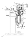
装置のコンパクト化を図るに好適な構造として、ボウル5をケーシング4の下方から取り出し可能な構成とする。すなわち、第1の実施形態の竪型遠心分離装置1は、図5に示されるように装置を自動で分解してボウル5をケーシング4の上方から取り出している。そのため、装置の上方側に少なくともボウル5の長さ以上の空間が必要となる。第1の実施形態のように自動でボウル5をケーシング4から取り出し可能な構造は、例えば作業員の負担を軽減できる点で有効である反面、装置が必要とする占有空間が大きくなってしまう。例えば食品や医薬の分野に適用される場合、クリーンルーム等の室内に設置されるので、装置に割り当て可能な空間が制限される。そのため、装置のコンパクト化を要求される場合がある。
As a structure suitable for reducing the size of the apparatus, the
そこで、第2の実施形態では、図7に示すように、ケーシング4を上ケーシング4Aと下ケーシング4Bに分割し、例えばクランプなどの固定手段によって上/下ケーシング4A,4Bの連結部4Cを脱着可能に連結した構造とする。従って、下ケーシング4Bを取り外すことでボウル5の下方部分を露出させ、例えば作業員が回転筒状体(すなわち、ボウル5と羽根部6)を回転軸52,62ごと下方に引き抜くことにより、ボウル5と羽根部6を取り外すことが可能となる。このように構成すると、上方にボウル5を持ち上げる場合に比べて実質的な装置の占有空間を小さくすることができ、装置のコンパクト化が可能となる。しかも、図1に例示したような、自動でボウル5をケーシング4から取り出すための可動フレーム22やその駆動機構が省略され、固定フレーム21で足りるので、その分においても装置がコンパクトとなり、また設備コストの軽減となる。なお、メインテナンスのために装置の分解を行う場合には、例えば、下ケーシング4Bを取り外し、さらに蓋部244と上ケーシング4Aとの連結部分から上ケーシング4Aを取り外し、羽根部6を回転軸62ごと取り外した後、ボウル5を回転軸52ごと取り外すようにすることができる。
Therefore, in the second embodiment, as shown in FIG. 7, the
また、本実施形態の下ケーシング4Bは、底面が一方向に傾斜した形状を呈し、その前端面に開閉自在な扉部45(例えば、マンホール)が設けられている。この場合、遠心分離によって一定量の固形物(ケーキ)がボウル5内に溜まると、羽根駆動用モータ73によって羽根部6を駆動させて固形物をボウル5内から排出し、続けて遠心分離を行うか、或いは一旦洗浄してから遠心分離を行う。そして、連続した遠心分離によって、ある程度の排出物(固形物や洗浄液)が下ケーシング4B内に溜まると、扉部45を開けてケーシング4内から固形物等を排出する。このように連続した遠心分離を行うことで、固形物をケーシング4から毎回排出する場合に比べて総処理時間を短縮することができる。
Further, the
さらに、装置のコンパクト化を図るに好適な構造として、本実施形態の竪型遠心分離装置1は、ボウル5の回転軸52を回転可能に支持する軸受機構521にベアリングを用い、さらに潤滑用のグリスをベアリングに自動で注入する方式を採用している。これにより、例えば装置のコンパクト化を図るためにボウル5を小径化しても、高速回転を維持させることが可能となる。
Furthermore, as a structure suitable for reducing the size of the apparatus, the vertical centrifuge 1 of the present embodiment uses a bearing for the
より詳しくは、ボウル5の直径を小さくして同じ遠心力を得ようとすると、直径が小さくなった分、ボウル5の回転速度を速くしなくてはならない。一例として、直径が14インチのボウル5で約2万Gの遠心力を得ようとすると約10000rpmの回転速度が必要であり、直径が10インチのボウル5で約2万Gの遠心力を得ようとすると約12000rpmの回転速度が必要である。しかし、ボウル5の回転速度を速くした分、軸受機構521のベアリングの負荷が大きくなる。ベアリングの仕様によっては、許容回転数を超えてしまう場合もある。
More specifically, if the diameter of the
そこで、本実施形態では、図8に示すように、回転軸52の軸方向に複数のボールベアリング8を配列し、各々のボールベアリング8に対して潤滑用のグリスを注入する注入孔81を形成している。さらに、隣り合うベアリング間にリング状部材(いわゆる、間座)82を配置し、この間座82にグリスを溜めるための貯留空間821を形成している。この間座82に形成した貯留空間821は、新たにグリスを注入することによってボールベアリング8から排出される余剰のグリスを貯留するためのものである。間座82は、内間座82Aと外間座82Bとを嵌合させた構成であり、ベアリング内部から貯留空間821へグリスを排出するための溝(不図示)が外間座82Bに形成されている。この溝は、貯留空間821に一旦排出されたグリスが、ベアリング内部に再突入するのを防止するようにベアリングの向きなどを考慮して形成されている。このように、不要なグリスがベアリング内部へ再突入するのを防止することによって、ベアリングの温度上昇を防止することが可能となる。各ボールベアリング8の注入孔81には、例えば配管やチューブなどのグリス供給路83が接続されており、さらに各グリス供給路83の基端側にグリス補給タンク84が接続されている。なお、図7には、回転軸52に沿って5個のボールベアリング8を配置しているが、ボールベアリング8の数が限定されることはない。
Therefore, in the present embodiment, as shown in FIG. 8, a plurality of ball bearings 8 are arranged in the axial direction of the
さらに、グリス補給タンク84には、加圧用及びグリス押出用の気体(例えば、空気や窒素など)を供給するために例えば配管やチューブなどの気体供給路85が接続されており、その基端側にコンプレッサーやボンベなどの気体供給源86が接続されている。気体供給路85は、タンク加圧用とグリス押出用の2系統を有し、各系統に開閉バルブ851,852が設けられている。従って、開閉バルブ852を開いてグリス補給タンク84内を加圧しておき、さらに開閉バルブ851を瞬間的に開いてピストン駆動させることにより、グリスがグリス供給路83に押し出され、各ボールベアリング8にグリスが略均等に注入される。グリスの注入量は、開閉バルブ851を開く時間と加圧する圧力によって調節することができる。開閉バルブ851を開くタイミングは、例えば図示しない制御装置に組み込んだシーケンスプログラムによって制御することができる。
Further, a
このような構成において、予めボールベアリング8内(貯留空間821を除く)に必要なグリス量を満たしておき、既述した手順で遠心分離を実行することにより、1年以上のメインテナンスフリーを可能にする。そして、その間は定期的に所定量のグリスを注入し、余剰(不要となった)のグリスは次回のメインテナンスで装置を分解するまで貯留空間821に溜めていく。好ましい一例として、1日1回、運転開始直後に約0.02ccのグリスを各ボールベアリング8に注入し、例えば1年周期で行うメインテナンス時に空間に溜まったグリスを除去するようにする。
In such a configuration, a grease amount necessary for the ball bearing 8 (excluding the storage space 821) is filled in advance, and centrifugation is performed according to the procedure described above, thereby enabling maintenance free for one year or more. To do. In the meantime, a predetermined amount of grease is periodically injected, and excess (unnecessary) grease is accumulated in the
例えば食品や医薬などに適用した場合には不純物の混入が問題視されるので、ボールベアリング8の潤滑剤としてグリスが選択される。しかし、グリスの場合、予め規定量をボールベアリング8内に満たして、装置を組み立てた後は、次に装置を分解するまで必要量のグリスがボールベアリング8内に残っているか確認することができない。そのため、ボウル5を小径化して更に回転速度を上げたときに、回転軸52の焼き付けが発生するのを防止できるかが問題となる。従って、本実施形態のように微量なグリスを定期的に注入し、余剰のグリスを排出すると共に再突入を防止する構成とすることで、ボールベアリング8内のグリスの量を最適に維持することができると共に、グリス補給時ベアリングの温度上昇を防止することができる。
For example, when it is applied to food or medicine, contamination of impurities is regarded as a problem, so that grease is selected as a lubricant for the ball bearing 8. However, in the case of grease, after a predetermined amount is filled in the ball bearing 8 in advance and the device is assembled, it cannot be confirmed whether the necessary amount of grease remains in the ball bearing 8 until the device is disassembled next time. . Therefore, it becomes a problem whether or not the burning of the
その結果、更なる高速回転を行っても焼き付け等の問題を防止することができるので、ボウル5を小径化して装置のコンパクト化を図ることが可能となる。また、作業員にとっても、メインテナンスのための労力が少なくなる利点がある。勿論、ボウル5の直径を変えずに回転速度を上げることによって、より高い遠心力を得るようにしてもよい。また、図8に示したボールベアリング8の構造は、図1に示した第1の実施形態の竪型遠心分離装置1に採用することもできる。
As a result, problems such as baking can be prevented even if the rotation is further increased, so that the diameter of the
本実施形態の竪型遠心分離装置1は、上述した装置のコンパクト化に好適な構造に加えて、封水洗浄を行うのに好適な構造を有している。この構造を有することにより、上述の噴射ノズル616,617による洗浄に加えて封水洗浄を行うことにより、より確実にケーシング4及び回転筒状体(ボウル5及び羽根部6)を清潔に保つことが可能となる。本実施形態の竪型遠心分離装置1は、上述の噴射ノズル616,617による洗浄の前か後、或いは同時に封水洗浄を実行可能な構成となっている。
The vertical centrifuge 1 of the present embodiment has a structure suitable for performing sealing water cleaning in addition to the structure suitable for making the apparatus compact as described above. By having this structure, the
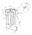
まず、図7或いは図9に示されるように、本実施形態の竪型遠心分離装置1は、図6に例示した羽根部本体61が組み込まれている。さらに、下方側に配置した供給管42を通じて洗浄液を供給していた第1の実施形態とは異なり、洗浄液の供給路である内部管614を軸部材611の上端まで延ばし、上方側から洗浄液を供給する。そのため、羽根駆動用モータ73によって回転される駆動軸にも洗浄液の供給路となる内部管を形成し、第1のシリンダ241によって軸部材611と駆動軸を結合させた状態にしてから、洗浄液を供給する。よって、本実施形態では、羽根駆動用モータ73の位置を変更し、プーリと回転ベルトによって回転軸を駆動させている。
First, as shown in FIG. 7 or FIG. 9, the vertical centrifugal separator 1 of this embodiment incorporates the
また、封水洗浄を行うにはケーシング4の気密性が必要となる。通常、ケーシング4の連結部分/接続部分に配置されるシール材としては、O−リングやガスケットなどの公知のシール材を使用することができ、充分なシール性が確保されるのであればシール材の種類が限定されることはない。しかし、例えば、部品点数が多くなると製作誤差等の影響を受けて充分なシール性が確保できない場合がある。そのため、特にシール性が不安視される箇所、例えば図9に示されるケーシング4の蓋部244と上ケーシング4Aとの連結部分に配置されるシール材9として、ゴム等の弾性素材でチューブ状に形成されたシール部材91を用いる。さらに、シール部材91の内部に加圧用の流体(例えば、空気や窒素など)を付勢供給するためのチューブ92を接続し、このチューブ92の基端にコンプレッサーやボンベなどの流体源(不図示)を接続し、その途中に開閉バルブ(不図示)を配置する。そして、例えば封水洗浄を行うタイミングに合わせて開閉バルブを開くか、或いは常時開いて加圧用の流体をシール部材91に付勢供給し、シール部材91を溝部内で膨張させ、これによって連結部の隙間をなくしてシールする。
Moreover, in order to perform sealing water cleaning, the airtightness of the
このようにケーシング4の気密性が確保された状態で、重液排出部43等の出口を塞ぎ、例えば既述のごとく噴射ノズル616,617から洗浄液を噴射してボウル5の内面と羽根部6を洗浄しながら、ケーシング4内に洗浄液を溜めていく。そして、オーバーフロー用の排出ノズル44から洗浄液が排出される位まで洗浄液を溜めて封水洗浄することによって、特に、噴射ノズル616,617では充分に洗浄できないボウル5の外面とケーシング4の内面を洗浄することができる。このとき、ケーシング4の内側上面まで洗浄液が満たされるように、排出ノズル44の出口にバルブを設けて排出量を調節するか、或いは洗浄液の供給圧力を高くすることができる。また、いわゆるデッドスペースとなり易いケーシング4内の内側上面及び上部隅部を洗浄するために、例えば図9に示す位置に噴射ノズル618を配置するようにしてもよい。
In the state where the airtightness of the
なお、本実施形態の竪型遠心分離装置1は、第1の実施形態における低速駆動用モータ72とリフター211を省略し、本体駆動用モータ71によって洗浄時にボウルを回転させる。すなわち、本実施形態は、本体駆動用と羽根駆動用の2つのモータ71,73によって構成されている。
In the vertical centrifuge 1 of this embodiment, the low-
以上、本発明を具体的な実施形態に則して詳細に説明したが、形式や細部についての種々の置換、変形、変更等が、特許請求の範囲の記載により規定されるような本発明の精神及び範囲から逸脱することなく行われることが可能であることは、当該技術分野における通常の知識を有する者には明らかである。従って、本発明の範囲は、前述の実施形態及び添付図面に限定されるものではなく、特許請求の範囲の記載及びこれと均等なものに基づいて定められるべきである。 Although the present invention has been described in detail with reference to specific embodiments, various substitutions, modifications, changes, etc. in form and detail are defined in the claims. It will be apparent to those skilled in the art that this can be done without departing from the spirit and scope. Therefore, the scope of the present invention should not be limited to the above-described embodiments and the accompanying drawings, but should be determined based on the description of the claims and equivalents thereof.
1 竪型遠心分離装置
4 ケーシング
4A 上ケーシング
4B 下ケーシング
5 ボウル
511 テーパー部(契合部)
53 インデックスリング(第1のリング状部材)
533,534,535 突起部
54 コイルばね(付勢手段)
6 羽根部(排出部材)
612 ウィング
613 テーパー部(契合部)
616 横噴射ノズル
617 縦噴射ノズル
63 インナーリング(第2のリング状部材)
71 本体駆動用モータ
72 低速駆動用モータ
73 羽根駆動用モータ
8 ボールベアリング
81 グリス注入孔
82 間座
821 グリス貯留空間DESCRIPTION OF SYMBOLS 1
53 Index ring (first ring-shaped member)
533, 534, 535
6 blade part (discharge member)
612
616
71 Motor for driving
Claims (12)
前記ケーシングに回転可能に収容された回転筒状体であり、内部に供給された被処理液を遠心力の作用により液体と固形物とに分離し、分離された液体と固形物をそれぞれの排出口から排出するためのボウルと、
前記ボウル内に回転可能に収容され、分離された固形物をボウル内から排出するための排出部材と、
を有し、
前記ボウル及び前記排出部材は、軸方向への相対移動により契合/契合解除する契合部と、前記ボウルと前記排出部材との一体回転時における動バランスを考慮した位置になるように、前記排出部材と前記ボウルとの位相を回転軸周りの少なくとも一箇所で位置合わせする位置合わせ機構と、を備え、被処理液の遠心分離時には前記位置合わせ機構による位相を保持した契合状態で一体に回転し、該契合状態の解除により相対回転可能となることを特徴とする竪型遠心分離装置。 A casing,
A rotating cylindrical body rotatably accommodated in the casing, wherein the liquid to be treated supplied therein is separated into a liquid and a solid by the action of a centrifugal force, and the separated liquid and the solid are respectively discharged. A bowl for discharging from the outlet;
A discharge member rotatably accommodated in the bowl and for discharging the separated solid matter from the bowl;
Have
The bowl and the discharge member are positioned so as to take into account a dynamic balance at the time of integral rotation of the bowl and the discharge member, and an engagement portion that engages / cancels engagement by relative movement in the axial direction. And an alignment mechanism that aligns the phase of the bowl with at least one position around the rotation axis , and when the liquid to be treated is centrifuged, the phase rotates with the alignment mechanism maintaining the phase by the alignment mechanism, A vertical centrifuge capable of relative rotation by releasing the engagement state.
前記排出部材は、複数のウィングが一体形成され前記ボウル本体内に収容される羽根部本体と、該羽根部本体から上方に突出し、前記ボウルの中空の回転軸内に回転可能に設けられる回転軸と、を備え、
前記契合部は、前記ボウル及び前記排出部材の下部側に設けられ、前記ボウルの内径及び前記羽根部本体のそれぞれの幅が下方になるに従ってテーパー状に広がるテーパー部を有し、前記排出部材が前記ボウルに対して上方に相対移動すると、前記ボウルの回転駆動時に前記排出部材が一体に回転する契合状態となる
ことを特徴とする請求項3記載の竪型遠心分離装置。 The bowl includes a bowl main body having a substantially cylindrical tank shape to which a liquid to be treated is supplied, and a hollow rotating shaft integrally provided at an upper portion of the bowl main body,
The discharge member includes a blade part body integrally formed with a plurality of wings and accommodated in the bowl body, and a rotation shaft that protrudes upward from the blade part body and is rotatably provided in the hollow rotation shaft of the bowl. And comprising
The engagement portion is provided on a lower side of the bowl and the discharge member, and has a tapered portion that expands in a tapered shape as the inner diameter of the bowl and the width of each blade portion main body are lowered, and the discharge member is 4. The vertical centrifuge according to claim 3 , wherein when the bowl is relatively moved upward with respect to the bowl, the discharging member is integrally rotated when the bowl is driven to rotate.
前記溝部及び突起部の各々は、前記回転軸の軸中心からなす角度が不等角になる位置に配置されたことを特徴とする請求項5記載の竪型遠心分離装置。 A plurality of the groove portions and the protrusion portions are provided, and when the respective rotation shafts are relatively rotated, each of the protrusion portions is disposed at a position fitted to each of the corresponding groove portions, and
6. The vertical centrifuge according to claim 5 , wherein each of the groove and the protrusion is disposed at a position where an angle formed from an axis center of the rotation shaft is an unequal angle.
前記シール機構が、ケーシングの連結部に配置され、その内部に加圧用の流体が付勢供給されると膨張してシール特性が向上するシール部材と、このシール部材に前記流体を供給する手段と、を含むことを特徴とする請求項1乃至8のいずれか記載の竪型遠心分離装置。 In order to seal and wash the bowl and the discharge member in the casing, further comprising a nozzle for supplying a cleaning liquid into the casing, and a sealing mechanism for making the casing airtight,
The seal mechanism is disposed at a connecting portion of the casing, and when a pressurizing fluid is urged and supplied therein, a seal member that expands to improve seal characteristics; and means for supplying the fluid to the seal member The vertical centrifuge according to any one of claims 1 to 8 , characterized by comprising:
を有し、前記中空軸の一端側から付勢供給された洗浄液を前記噴射ノズルから外方に噴射することで前記排出部材及びボウル内部を洗浄する洗浄機構を備えたことを特徴とする請求項1乃至9のいずれか記載の竪型遠心分離装置。 The discharge member includes a hollow shaft provided in a portion accommodated in the bowl, an injection nozzle provided to communicate with the hollow shaft,
And a cleaning mechanism for cleaning the inside of the discharge member and the bowl by spraying a cleaning liquid biased and supplied from one end side of the hollow shaft outward from the spray nozzle. The vertical centrifuge according to any one of 1 to 9 .
ことを特徴とする請求項10記載の竪型遠心分離装置。 The injection nozzle, the urging supplied washing liquid with jetted toward the discharge member, according to claim 10, wherein the cleaning liquid reflected from the discharge member, characterized in that disposed in the position corresponding to the inner wall of the bowl Vertical centrifuge.
該固定フレームに対して上下移動可能に設けられる上下動フレームと、
前記ボウルが取付けられるとともに、前記排出部材が着脱可能に取付けられ、前記上下動フレームに対して回動可能に設けられる回動フレームと、を備え、
前記上下動フレームが上昇させられることにより、前記ボウル及び前記排出部材が前記ケーシングから引き抜かれ、
前記回動フレームの回動後に前記上下動フレームが下降させられることにより、前記排出部材を前記回動フレームから離脱させるための分解機構を備えた
ことを特徴とする請求項1乃至11のいずれか記載の竪型遠心分離装置。 A fixed frame integral with the casing;
A vertically moving frame provided to be movable up and down with respect to the fixed frame;
The bowl is attached, the discharge member is detachably attached, and a rotation frame provided rotatably with respect to the vertical movement frame,
By raising the vertical movement frame, the bowl and the discharge member are pulled out from the casing,
By the vertical movement frame is lowered after rotation of the rotating frame, any one of claims 1 to 11, comprising the degradation mechanism for disengaging said discharge member from said rotating frame The vertical centrifuge of the description.
Priority Applications (1)
| Application Number | Priority Date | Filing Date | Title |
|---|---|---|---|
| JP2010547451A JP5512552B2 (en) | 2009-01-26 | 2010-01-26 | Vertical centrifuge |
Applications Claiming Priority (4)
| Application Number | Priority Date | Filing Date | Title |
|---|---|---|---|
| JP2009014305 | 2009-01-26 | ||
| JP2009014305 | 2009-01-26 | ||
| PCT/JP2010/000418 WO2010084782A1 (en) | 2009-01-26 | 2010-01-26 | Vertical-type centrifugal separation apparatus |
| JP2010547451A JP5512552B2 (en) | 2009-01-26 | 2010-01-26 | Vertical centrifuge |
Publications (2)
| Publication Number | Publication Date |
|---|---|
| JPWO2010084782A1 JPWO2010084782A1 (en) | 2012-07-19 |
| JP5512552B2 true JP5512552B2 (en) | 2014-06-04 |
Family
ID=42355837
Family Applications (1)
| Application Number | Title | Priority Date | Filing Date |
|---|---|---|---|
| JP2010547451A Active JP5512552B2 (en) | 2009-01-26 | 2010-01-26 | Vertical centrifuge |
Country Status (4)
| Country | Link |
|---|---|
| US (1) | US9005097B2 (en) |
| JP (1) | JP5512552B2 (en) |
| CA (1) | CA2750286A1 (en) |
| WO (1) | WO2010084782A1 (en) |
Families Citing this family (20)
| Publication number | Priority date | Publication date | Assignee | Title |
|---|---|---|---|---|
| JP5571919B2 (en) * | 2009-07-31 | 2014-08-13 | 巴工業株式会社 | Vertical centrifuge and method for recovering centrifuge liquid |
| JP2014151276A (en) * | 2013-02-08 | 2014-08-25 | Flowserve Japan Co Ltd | Vertical type solid-liquid separation machine |
| JP6040311B2 (en) * | 2013-06-14 | 2016-12-07 | 巴工業株式会社 | Centrifuge |
| JP5475919B1 (en) * | 2013-11-01 | 2014-04-16 | 巴工業株式会社 | Sealed decanter centrifuge |
| JP6023369B1 (en) * | 2016-02-22 | 2016-11-09 | 巴工業株式会社 | Centrifuge |
| EP3257587B1 (en) | 2016-06-14 | 2018-12-26 | Alfa Laval Corporate AB | Centrifugal separator with dismountable bowl-hood |
| CN107008577A (en) * | 2017-06-09 | 2017-08-04 | 大连隆田科技有限公司 | A vertical spiral liquid-solid centrifuge with automatic cleaning function |
| US10814338B2 (en) | 2017-08-09 | 2020-10-27 | Delta Separations, Llc | Device, system and methods for separation and purification of organic compounds from botanical material |
| US12303917B2 (en) * | 2017-10-19 | 2025-05-20 | Adalberto Mercado Alvarado | Substance separator system driven by a submersible actuator |
| CN109248792B (en) * | 2018-11-01 | 2024-03-08 | 象山蓝越食品机械制造有限公司 | Dewatering machine |
| CN109985733B (en) * | 2019-05-10 | 2024-02-23 | 辽宁贝克瑞生物科技有限公司 | Tubular centrifuge |
| CN111054528B (en) * | 2019-12-12 | 2024-02-02 | 武汉德泽环保科技有限公司 | Piston pushing centrifugal machine and feeding method thereof |
| CN112661286B (en) * | 2020-12-23 | 2024-03-29 | 马佳婷 | Energy-saving and environment-friendly sewage rapid centrifugal dialysis treatment mechanism |
| WO2022155136A1 (en) * | 2021-01-12 | 2022-07-21 | The Regents Of The University Of Colorado, A Body Corporate | Continuous centrifugal isolating system and methods of use thereof |
| CN114889843B (en) * | 2022-05-17 | 2024-06-07 | 中国工程物理研究院总体工程研究所 | High-precision measuring and calculating method for axial and tangential overload output of centrifugal machine |
| CN116673130B (en) * | 2023-08-02 | 2023-10-17 | 山东芝圣堂生物科技有限公司 | Centrifugal machine for extracting spore oil |
| CN117548244B (en) * | 2024-01-11 | 2024-04-09 | 江苏赛德力制药机械制造有限公司 | Residual filter cake scraping structure applied to centrifugal machine |
| EP4667111A1 (en) * | 2024-06-17 | 2025-12-24 | Alfa Laval Corporate AB | A centrifugal separator |
| CN120394207B (en) * | 2025-07-03 | 2025-09-12 | 江西天奇金泰阁钴业有限公司 | Ternary precursor slurry centrifugal solid-liquid separation device |
| CN120502442B (en) * | 2025-07-22 | 2025-11-18 | 福建常青新能源科技有限公司 | A washing device for lithium-rich manganese ternary material precursors |
Citations (6)
| Publication number | Priority date | Publication date | Assignee | Title |
|---|---|---|---|---|
| JPS5318060A (en) * | 1976-08-02 | 1978-02-18 | Neos Kk | Centrifugal separator |
| JPS55153147U (en) * | 1979-04-19 | 1980-11-05 | ||
| JPH08131894A (en) * | 1994-11-15 | 1996-05-28 | Trinity Ind Corp | Sludge recovering device |
| JP2005066711A (en) * | 2003-08-25 | 2005-03-17 | Yutaka Seimitsu Kogyo Ltd | Cutting fluid / chip separator |
| JP2005522321A (en) * | 2002-04-12 | 2005-07-28 | ワグナー デベロップメント インコーポレイテッド | Centrifuge that discharges solids using scraper or piston |
| JP2007190493A (en) * | 2006-01-19 | 2007-08-02 | Nagano Seisakusho:Kk | Sludge recovery apparatus |
Family Cites Families (8)
| Publication number | Priority date | Publication date | Assignee | Title |
|---|---|---|---|---|
| JPS55153147A (en) | 1979-05-18 | 1980-11-28 | Matsushita Electric Ind Co Ltd | Tape recorder |
| EP0056511A3 (en) * | 1981-01-19 | 1984-07-11 | The Chartwell House Group Limited | Improved centrifuge and method of cleaning a centrifuge drum |
| US5743840A (en) * | 1996-06-24 | 1998-04-28 | Carr Separations, Inc. | Centrifuge with a heating jacket for drying collected solids |
| US5908376A (en) * | 1997-09-11 | 1999-06-01 | Costner Industries Nevada, Inc. | Self-cleaning rotor for a centrifugal separator |
| US6126587A (en) * | 1998-04-08 | 2000-10-03 | U.S. Centrifuge | Centrifugal separator apparatus including a plow blade assembly |
| DE10314118B4 (en) * | 2003-03-28 | 2005-05-12 | Westfalia Separator Ag | Drive device for a separator |
| US7396324B2 (en) * | 2003-10-17 | 2008-07-08 | Hitachi Koki Co., Ltd. | Centrifugal separator with first and second control panels |
| WO2007086114A1 (en) | 2006-01-25 | 2007-08-02 | Tomoe Engineering Co., Ltd. | Vertical centrifugal machine |
-
2010
- 2010-01-26 WO PCT/JP2010/000418 patent/WO2010084782A1/en not_active Ceased
- 2010-01-26 US US13/146,077 patent/US9005097B2/en not_active Expired - Fee Related
- 2010-01-26 JP JP2010547451A patent/JP5512552B2/en active Active
- 2010-01-26 CA CA2750286A patent/CA2750286A1/en not_active Abandoned
Patent Citations (6)
| Publication number | Priority date | Publication date | Assignee | Title |
|---|---|---|---|---|
| JPS5318060A (en) * | 1976-08-02 | 1978-02-18 | Neos Kk | Centrifugal separator |
| JPS55153147U (en) * | 1979-04-19 | 1980-11-05 | ||
| JPH08131894A (en) * | 1994-11-15 | 1996-05-28 | Trinity Ind Corp | Sludge recovering device |
| JP2005522321A (en) * | 2002-04-12 | 2005-07-28 | ワグナー デベロップメント インコーポレイテッド | Centrifuge that discharges solids using scraper or piston |
| JP2005066711A (en) * | 2003-08-25 | 2005-03-17 | Yutaka Seimitsu Kogyo Ltd | Cutting fluid / chip separator |
| JP2007190493A (en) * | 2006-01-19 | 2007-08-02 | Nagano Seisakusho:Kk | Sludge recovery apparatus |
Also Published As
| Publication number | Publication date |
|---|---|
| US9005097B2 (en) | 2015-04-14 |
| US20110301013A1 (en) | 2011-12-08 |
| JPWO2010084782A1 (en) | 2012-07-19 |
| CA2750286A1 (en) | 2010-07-26 |
| WO2010084782A1 (en) | 2010-07-29 |
Similar Documents
| Publication | Publication Date | Title |
|---|---|---|
| JP5512552B2 (en) | Vertical centrifuge | |
| US10573507B2 (en) | Substrate processing apparatus and substrate processing method | |
| US9484230B2 (en) | Substrate liquid processing apparatus | |
| KR20160025770A (en) | dipping and omissing device for surface treatment object | |
| JP6279954B2 (en) | Substrate processing equipment | |
| KR20180011732A (en) | Substrate treating apparatus | |
| DK3065876T3 (en) | CLEANING DEVICE WITH ROTATING PRELET BREAD AND REPLACEABLE PATTERN DRIVE | |
| CN110813552B (en) | A flat plate sedimentation type fully automatic centrifuge | |
| US9421582B1 (en) | Pivoting centrifugal parts cleaner | |
| JPH0347574B2 (en) | ||
| WO2016019876A1 (en) | Drum washing machine | |
| CN1706567A (en) | Cleaning device and valve equipment including the device | |
| JP6280789B2 (en) | Substrate processing apparatus and substrate processing method | |
| JP6040311B2 (en) | Centrifuge | |
| CN101198413A (en) | Improved Centrifuge to Avoid Cross Contamination | |
| JP2009082808A (en) | centrifuge | |
| JP6107173B2 (en) | Centrifuge rotor and centrifuge | |
| KR200284275Y1 (en) | A centrifugal-specific gravity separator which can refine oil | |
| CN117612932B (en) | Wafer cleaning method and cleaning device | |
| CN222279790U (en) | Cantilever type double-shaft testing turntable structure | |
| JP2005132383A (en) | Container processing device and cleaning device | |
| JP5308291B2 (en) | Substrate cleaning device | |
| JP4383424B2 (en) | Decanter centrifuge and cleaning method thereof | |
| JP2009106940A (en) | centrifuge | |
| JP6023369B1 (en) | Centrifuge |
Legal Events
| Date | Code | Title | Description |
|---|---|---|---|
| A621 | Written request for application examination |
Free format text: JAPANESE INTERMEDIATE CODE: A621 Effective date: 20121220 |
|
| A131 | Notification of reasons for refusal |
Free format text: JAPANESE INTERMEDIATE CODE: A131 Effective date: 20131022 |
|
| RD03 | Notification of appointment of power of attorney |
Free format text: JAPANESE INTERMEDIATE CODE: A7423 Effective date: 20131125 |
|
| A521 | Request for written amendment filed |
Free format text: JAPANESE INTERMEDIATE CODE: A523 Effective date: 20131217 |
|
| TRDD | Decision of grant or rejection written | ||
| A01 | Written decision to grant a patent or to grant a registration (utility model) |
Free format text: JAPANESE INTERMEDIATE CODE: A01 Effective date: 20140325 |
|
| A61 | First payment of annual fees (during grant procedure) |
Free format text: JAPANESE INTERMEDIATE CODE: A61 Effective date: 20140326 |
|
| R150 | Certificate of patent or registration of utility model |
Ref document number: 5512552 Country of ref document: JP Free format text: JAPANESE INTERMEDIATE CODE: R150 |
|
| R250 | Receipt of annual fees |
Free format text: JAPANESE INTERMEDIATE CODE: R250 |
|
| R250 | Receipt of annual fees |
Free format text: JAPANESE INTERMEDIATE CODE: R250 |
|
| R250 | Receipt of annual fees |
Free format text: JAPANESE INTERMEDIATE CODE: R250 |
|
| R250 | Receipt of annual fees |
Free format text: JAPANESE INTERMEDIATE CODE: R250 |
|
| R250 | Receipt of annual fees |
Free format text: JAPANESE INTERMEDIATE CODE: R250 |
|
| R250 | Receipt of annual fees |
Free format text: JAPANESE INTERMEDIATE CODE: R250 |
|
| R250 | Receipt of annual fees |
Free format text: JAPANESE INTERMEDIATE CODE: R250 |