JP5507300B2 - Braking device for saddle-ride type vehicles - Google Patents
Braking device for saddle-ride type vehicles Download PDFInfo
- Publication number
- JP5507300B2 JP5507300B2 JP2010064199A JP2010064199A JP5507300B2 JP 5507300 B2 JP5507300 B2 JP 5507300B2 JP 2010064199 A JP2010064199 A JP 2010064199A JP 2010064199 A JP2010064199 A JP 2010064199A JP 5507300 B2 JP5507300 B2 JP 5507300B2
- Authority
- JP
- Japan
- Prior art keywords
- brake
- swing arm
- pipe
- cover
- rear wheel
- Prior art date
- Legal status (The legal status is an assumption and is not a legal conclusion. Google has not performed a legal analysis and makes no representation as to the accuracy of the status listed.)
- Active
Links
Images


Classifications
-
- B—PERFORMING OPERATIONS; TRANSPORTING
- B62—LAND VEHICLES FOR TRAVELLING OTHERWISE THAN ON RAILS
- B62K—CYCLES; CYCLE FRAMES; CYCLE STEERING DEVICES; RIDER-OPERATED TERMINAL CONTROLS SPECIALLY ADAPTED FOR CYCLES; CYCLE AXLE SUSPENSIONS; CYCLE SIDE-CARS, FORECARS, OR THE LIKE
- B62K25/00—Axle suspensions
- B62K25/04—Axle suspensions for mounting axles resiliently on cycle frame or fork
- B62K25/28—Axle suspensions for mounting axles resiliently on cycle frame or fork with pivoted chain-stay
- B62K25/283—Axle suspensions for mounting axles resiliently on cycle frame or fork with pivoted chain-stay for cycles without a pedal crank, e.g. motorcycles
-
- B—PERFORMING OPERATIONS; TRANSPORTING
- B62—LAND VEHICLES FOR TRAVELLING OTHERWISE THAN ON RAILS
- B62L—BRAKES SPECIALLY ADAPTED FOR CYCLES
- B62L1/00—Brakes; Arrangements thereof
- B62L1/005—Brakes; Arrangements thereof constructional features of brake elements, e.g. fastening of brake blocks in their holders
-
- B—PERFORMING OPERATIONS; TRANSPORTING
- B62—LAND VEHICLES FOR TRAVELLING OTHERWISE THAN ON RAILS
- B62J—CYCLE SADDLES OR SEATS; AUXILIARY DEVICES OR ACCESSORIES SPECIALLY ADAPTED TO CYCLES AND NOT OTHERWISE PROVIDED FOR, e.g. ARTICLE CARRIERS OR CYCLE PROTECTORS
- B62J45/00—Electrical equipment arrangements specially adapted for use as accessories on cycles, not otherwise provided for
- B62J45/40—Sensor arrangements; Mounting thereof
- B62J45/41—Sensor arrangements; Mounting thereof characterised by the type of sensor
- B62J45/412—Speed sensors
-
- B—PERFORMING OPERATIONS; TRANSPORTING
- B62—LAND VEHICLES FOR TRAVELLING OTHERWISE THAN ON RAILS
- B62K—CYCLES; CYCLE FRAMES; CYCLE STEERING DEVICES; RIDER-OPERATED TERMINAL CONTROLS SPECIALLY ADAPTED FOR CYCLES; CYCLE AXLE SUSPENSIONS; CYCLE SIDE-CARS, FORECARS, OR THE LIKE
- B62K11/00—Motorcycles, engine-assisted cycles or motor scooters with one or two wheels
- B62K11/02—Frames
-
- B—PERFORMING OPERATIONS; TRANSPORTING
- B62—LAND VEHICLES FOR TRAVELLING OTHERWISE THAN ON RAILS
- B62L—BRAKES SPECIALLY ADAPTED FOR CYCLES
- B62L3/00—Brake-actuating mechanisms; Arrangements thereof
- B62L3/02—Brake-actuating mechanisms; Arrangements thereof for control by a hand lever
-
- B—PERFORMING OPERATIONS; TRANSPORTING
- B62—LAND VEHICLES FOR TRAVELLING OTHERWISE THAN ON RAILS
- B62L—BRAKES SPECIALLY ADAPTED FOR CYCLES
- B62L5/00—Brakes, or actuating mechanisms therefor, controlled by back-pedalling
- B62L5/003—Brakes, or actuating mechanisms therefor, controlled by back-pedalling the brakes being arranged apart from the rear wheel hub
-
- F—MECHANICAL ENGINEERING; LIGHTING; HEATING; WEAPONS; BLASTING
- F16—ENGINEERING ELEMENTS AND UNITS; GENERAL MEASURES FOR PRODUCING AND MAINTAINING EFFECTIVE FUNCTIONING OF MACHINES OR INSTALLATIONS; THERMAL INSULATION IN GENERAL
- F16D—COUPLINGS FOR TRANSMITTING ROTATION; CLUTCHES; BRAKES
- F16D2121/00—Type of actuator operation force
- F16D2121/02—Fluid pressure
Description
本発明は、鞍乗り型車両の制動装置に関する。 The present invention relates to a braking device for a saddle-ride type vehicle.
自動二輪車の後輪用制動装置には、ブレーキキャリパとマスタシリンダを接続するブレーキ配管をスイングアームの上面に配置し、この上面に配置されたブレーキ配管を覆って可動範囲を規制するホースガイドを設けた構造が知られている(例えば、特許文献1参照)。 The brake device for the rear wheel of a motorcycle is provided with a brake pipe that connects the brake caliper and the master cylinder on the upper surface of the swing arm, and a hose guide that covers the brake pipe arranged on the upper surface and regulates the movable range is provided. Such a structure is known (see, for example, Patent Document 1).
しかし、従来の構造は、ホースガイドを別体に形成するため、部品点数が増加してしまう。この部品点数の増大を回避するためにホースガイドを廃したとすると、ブレーキ配管が外観に露出し、ブレーキ配管の保護を図るために配管自体の耐久性を向上させる必要が生じ、重量増となってしまう。 However, since the conventional structure forms the hose guide separately, the number of parts increases. If the hose guide is abolished to avoid this increase in the number of parts, the brake piping is exposed to the exterior, and it is necessary to improve the durability of the piping itself in order to protect the brake piping, resulting in an increase in weight. End up.
本発明は、上述した事情を鑑みてなされたものであり、部品点数を削減しつつスイングアームに配設される配管を保護可能にした鞍乗り型車両の制動装置を提供することを目的としている。 The present invention has been made in view of the above-described circumstances, and an object of the present invention is to provide a braking device for a saddle-ride type vehicle that can protect the piping disposed on the swing arm while reducing the number of parts. .
上述した課題を解決するため、本発明は、車体フレーム(2)と、車体フレーム(2)に揺動可能に懸架されるスイングアーム(35)と、スイングアーム(35)の自由端側に回転自在に支持される後輪(26)と、スイングアーム(35)の自由端側に配置される後輪用ブレーキ装置(102)と、スイングアーム(35)の軸支部近傍で車体フレーム(2)に固定されるブレーキ操作子(81)と、スイングアーム(35)上面に配策され、ブレーキ操作子(81)のブレーキ操作を後輪用ブレーキ装置(102)に伝達するブレーキ配管(103)とを備える鞍乗り型車両の制動装置において、前記後輪(26)の前方および上方の一部を覆うカバー(151)を備え、このカバー(151)は、前記スイングアーム(35)に設けられ、前記ブレーキ配管(103)を車幅方向外側から覆う配管カバー部(154)を有するカバー形状に形成され、前記カバー(151)は、前記後輪(26)を挟んで前記後輪用ブレーキ装置(102)と逆側に設けられるチェーン(34)の車幅方向外側を覆うチェーンカバー部(156)を備えることを特徴とする。
この構成によれば、後輪の前方および上方の一部を覆うカバーは、スイングアーム上面のブレーキ配管を車幅方向外側から覆う配管カバー部を有するカバー形状に形成されるので、スイングアーム上面のブレーキ配管を、部品点数を削減しつつ保護することができる。
In order to solve the above-described problems, the present invention rotates the vehicle body frame (2), the swing arm (35) swingably suspended from the vehicle body frame (2), and the free end side of the swing arm (35). A rear wheel (26) that is freely supported, a rear wheel brake device (102) that is disposed on the free end side of the swing arm (35), and a vehicle body frame (2) in the vicinity of the shaft support portion of the swing arm (35). And a brake pipe (103) arranged on the upper surface of the swing arm (35) for transmitting the brake operation of the brake operator (81) to the rear wheel brake device (102). A brake device for a saddle-ride type vehicle including a cover (151) that covers a part of the front and upper sides of the rear wheel (26), and the cover (151) is provided on the swing arm (35). Is, the formed brake piping (103) to a cover shape having a pipe cover which covers the vehicle width direction outside (the 154), said cover (151), the rear wheel brake to sandwich the rear wheel (26) device (102) and the chain cover section that covers the vehicle width direction outer side of the chain (34) provided on the opposite side provided with a (156) and said Rukoto.
According to this configuration, the cover that covers a part of the front and upper part of the rear wheel is formed in a cover shape having a pipe cover portion that covers the brake pipe on the upper surface of the swing arm from the outside in the vehicle width direction. Brake piping can be protected while reducing the number of parts.
また、本発明は、車体フレーム(2)と、車体フレーム(2)に揺動可能に懸架されるスイングアーム(35)と、スイングアーム(35)の自由端側に回転自在に支持される後輪(26)と、スイングアーム(35)の自由端側に配置される後輪用ブレーキ装置(102)と、スイングアーム(35)の軸支部近傍で車体フレーム(2)に固定されるブレーキ操作子(81)と、スイングアーム(35)上面に配策され、ブレーキ操作子(81)のブレーキ操作を後輪用ブレーキ装置(102)に伝達するブレーキ配管(103)とを備える鞍乗り型車両の制動装置において、前記後輪(26)の前方および上方の一部を覆うカバー(151)を備え、このカバー(151)は、前記スイングアーム(35)に設けられ、前記ブレーキ配管(103)を車幅方向外側から覆う配管カバー部(154)を有するカバー形状に形成され、前記カバー(151)は、後輪(26)の接地面に対向する後輪カバー部(152)と前記配管カバー部(154)とを備え、前記配管カバー部(154)の車幅方向外側面は、前記スイングアーム(35)の車幅方向外側面と車幅方向で略同じ位置に形成され、前記スイングアーム(35)に、上方に延出して前記カバーを支持する支持ステー(165)を設け、前記支持ステー(165)は、前後に間隔を空けて配置される前側支持ステー(165A)と、後側支持ステー(165B)とを備え、前記ブレーキ配管(103)は、側面視で、前記後側支持ステー(165B)よりも前方で、前記カバー(151)の前端よりも後方側から外側に露出するように設けられることを特徴とする。
この構成によれば、配管カバー部の車幅方向外側面は、スイングアームの車幅方向外側面と車幅方向で略同じ位置に形成されるので、配管カバー部とスイングアームとの一体感を創出し、外観性を向上させることができる。
The present invention also includes a body frame (2), a swing arm (35) swingably suspended on the body frame (2), and a rear end rotatably supported on the free end side of the swing arm (35). The wheel (26), the rear wheel brake device (102) disposed on the free end side of the swing arm (35), and the brake operation fixed to the vehicle body frame (2) in the vicinity of the shaft support portion of the swing arm (35) A saddle-ride type vehicle including a child (81) and a brake pipe (103) arranged on the upper surface of the swing arm (35) and transmitting the brake operation of the brake operator (81) to the rear wheel brake device (102) The brake device includes a cover (151) that covers a part of the front and upper part of the rear wheel (26). The cover (151) is provided on the swing arm (35), and the brake pipe 103) is formed in a cover shape having a pipe cover portion (154) that covers the vehicle width direction from the outside, and the cover (151) includes the rear wheel cover portion (152) facing the ground contact surface of the rear wheel (26) and the A pipe cover portion (154), and an outer surface in the vehicle width direction of the pipe cover portion (154) is formed at substantially the same position in the vehicle width direction as the outer surface in the vehicle width direction of the swing arm (35), The swing arm (35) is provided with a support stay (165) that extends upward to support the cover, and the support stay (165) includes a front support stay (165A) that is disposed at a distance in the front-rear direction. A rear support stay (165B), and the brake pipe (103) is in front of the rear support stay (165B) and outward from the rear side of the front end of the cover (151) in a side view. And which are located so as to exit.
According to this configuration, the vehicle width direction outer side of the pipe cover portion, a sense of unity because it is formed substantially the same position in the vehicle width direction outer side in the vehicle width direction of the swing arm, the piping cover portion and the swing arm Can improve the appearance.
また、上記構成において、前記スイングアーム(35)に、上方に延出して前記カバーを支持する支持ステー(165)を設け、前記支持ステー(165)内側の前記スイングアーム(35)上面に前記ブレーキ配管(103)を配索し、前記ブレーキ配管(103)の車幅方向内側のスイングアーム(35)上面に、車幅方向外側に開放し、前記ブレーキ配管(103)を係止する係止部(164)を設けるようにしてもよい。
この構成によれば、ブレーキ配管は、車幅方向外側に開放する係止部で係止されるので、簡易な構成でブレーキ配管を係止することができる。また、係止部からブレーキ配管が抜ける側に、支持ステーが位置するので、支持ステーを、ブレーキ配管の抜け止めとして兼用させることができ、部品点数をより削減し、生産性の向上及びコスト低減を図ることができる。
In the above structure, the swing arm (35) extends upwardly to provide a support stay (165) for supporting the cover, the brake on the support stay (165) the swing arm (35) the upper surface of the inner A locking portion for routing the pipe (103), opening on the upper surface of the swing arm (35) on the inner side in the vehicle width direction of the brake pipe (103), and opening the outer side in the vehicle width direction to lock the brake pipe (103). (164) may be provided.
According to this configuration, since the brake pipe is locked by the locking portion that opens to the outside in the vehicle width direction, the brake pipe can be locked with a simple configuration. In addition, since the support stay is located on the side where the brake pipe comes out from the locking part, the support stay can be used as a brake pipe retainer, reducing the number of parts, improving productivity and reducing costs. Can be achieved.
また、上記構成において、前記後輪カバー部(152)の外縁(152R)と前記配管カバー部(154)の外縁(154R)とは、上面視で前方に凸の切り欠き部(155)を形成し、前記スイングアーム(35)上面の前記ブレーキ配管(103)が、前記切り欠き部(155)を通って前記スイングアーム(35)上面から離間するようにしてもよい。
この構成によれば、ブレーキ配管は、後輪カバー部の外縁と配管カバー部の外縁とで形成される上面視で前方に凸の切り欠き部を通って、スイングアーム上面から離間するので、切り欠き部によりブレーキ配管とカバーとの干渉を抑制しつつ、ブレーキ配管を保護することができる。
In the above configuration, the outer edge (152R) of the rear wheel cover part (152) and the outer edge (154R) of the pipe cover part (154) form a notch part (155) that protrudes forward in a top view. The brake pipe (103) on the upper surface of the swing arm (35) may be separated from the upper surface of the swing arm (35) through the notch (155).
According to this configuration, the brake pipe passes through a notch portion that protrudes forward in the top view formed by the outer edge of the rear wheel cover portion and the outer edge of the pipe cover portion, and is separated from the upper surface of the swing arm. The brake pipe can be protected while the interference between the brake pipe and the cover is suppressed by the notch.
また、上記構成において、前記リヤブレーキ装置(102)は、前記スイングアーム(35)の上方かつ後輪軸(26A)の前方に配置され、前記配管カバー部(154)が、前記リヤブレーキ装置(102)と前記ブレーキ配管(103)とのジョイント部(125A)と前後方向で重なるようにしてもよい。
この構成によれば、配管カバー部は、スイングアームの上方かつ後輪軸の前方に配置されるリヤブレーキ装置とブレーキ配管とのジョイント部と、前後方向で重なるので、リヤブレーキ装置に連結されるブレーキ配管を覆う配管カバー部の領域を可及的に少なくすることができ、配管カバー部の軽量化を図ることができる。
In the above configuration, the rear brake device (102) is disposed above the swing arm (35) and in front of the rear wheel shaft (26A), and the pipe cover portion (154) is disposed on the rear brake device (102). ) And the brake pipe (103) and the joint portion (125A) may overlap in the front-rear direction.
According to this configuration, the pipe cover portion overlaps the joint portion between the rear brake device and the brake pipe disposed above the swing arm and in front of the rear wheel shaft in the front-rear direction, so that the brake connected to the rear brake device The area of the piping cover portion covering the piping can be reduced as much as possible, and the weight of the piping cover portion can be reduced.
また、上記構成において、後輪(26)の回転速度を検出する車輪速センサ(116)を備え、この車輪速センサ(116)から延びる配線(132)を前記配管カバー部(154)で覆うようにしてもよい。この構成によれば、配管カバー部を、車輪速センサの配線を保護する保護部材に兼用でき、部品点数を増やすことなく配線を保護できる。
また、上記構成において、前記リヤブレーキ装置(102)は、油圧制動装置であり、前記ブレーキ操作子に連結されるマスタシリンダ(84)と、前記マスタシリンダ(84)に接続されるリザーブタンク(171)とを有し、前記リザーブタンク(171)は、高さ方向の長さを最大とし、車幅方向の長さを最小とするとともに、前記カバー(151)の車幅方向外側で、前記スイングアーム(35)が上方に揺動したときに前記カバー(151)と側面視で重なる位置に配置されるようにしてもよい。
この構成によれば、リザーブタンクは、高さ方向の長さを最大とし、車幅方向の長さを最小とするとともに、カバーの車幅方向外側で、スイングアームが上方に揺動したときにカバーと側面視で重なる位置に配置されるので、カバーがブレーキ配管の車幅方向外側を覆う形状であっても、リザーブタンクを車幅方向外側に張り出さずに配置することができる。
また、上記構成において、前記カバー(151)は、前記後輪(26)を挟んで前記後輪用ブレーキ装置(102)と逆側に設けられるチェーン(34)の車幅方向外側を覆うチェーンカバー部(156)を備えるようにしてもよい。また、上記構成において、前記スイングアーム(35)に、上方に延出して前記カバーを支持する支持ステー(165)を設け、前記支持ステー(165)は、前後に間隔を空けて配置される前側支持ステー(165A)と、後側支持ステー(165B)とを備え、前記ブレーキ配管(103)は、側面視で、前記前側支持ステー(165A)よりも前方で、前記カバー(151)の前端よりも後方側から外側に露出するように設けられるようにしてもよい。また、上記構成において、前記リヤブレーキ装置(102)と前記ブレーキ配管(103)とのジョイント部(125A)を有し、前記ジョイント部(125A)には、前記ブレーキ配管(103)が連結される配管連結部材(126)が設けられ、前記配管連結部材(125B)の軸線(LF)は車両前上方に傾斜し、前記ブレーキ配管(103)は、前記配管連結部材(126)の軸線(LF)を中心に回動自在に連結されるとともに、前記配管連結部材(125B)から前下がりに延びる前下がり配管部(103A)を備えるようにしてもよい。
前記リヤブレーキ装置(102)と前記ブレーキ配管(103)とのジョイント部(125A)を有し、前記ジョイント部(125A)には、前記ブレーキ配管(103)が連結される配管連結部材(126)が設けられ、前記配管連結部材(125B)の軸線(LF)は車両前上方に傾斜し、前記ブレーキ配管(103)は、前記配管連結部材(126)の軸線(LF)を中心に回動自在に連結されるとともに、前記配管連結部材(125B)から前下がりに延びる前下がり配管部(103A)を備えるようにしてもよい。
Further, in the above configuration, a wheel speed sensor (116) for detecting the rotational speed of the rear wheel (26) is provided, and the wiring (132) extending from the wheel speed sensor (116) is covered with the pipe cover portion (154). It may be. According to this configuration, the piping cover portion can be used as a protective member for protecting the wiring of the wheel speed sensor, and the wiring can be protected without increasing the number of parts.
In the above configuration, the rear brake device (102) is a hydraulic brake device, and a master cylinder (84) coupled to the brake operator and a reserve tank (171) coupled to the master cylinder (84). The reserve tank (171) has a maximum length in the height direction, a minimum length in the vehicle width direction, and the swing tank outside the cover (151) in the vehicle width direction. When the arm (35) swings upward, the arm (35) may be disposed at a position overlapping the cover (151) in a side view.
According to this configuration, the reserve tank has the maximum length in the height direction and the minimum length in the vehicle width direction, and when the swing arm swings upward on the outer side in the vehicle width direction of the cover. Since the cover is disposed at a position overlapping the cover in a side view, the reserve tank can be disposed without projecting outward in the vehicle width direction even if the cover covers the outer side in the vehicle width direction of the brake pipe.
In the above configuration, the cover (151) covers the outer side in the vehicle width direction of the chain (34) provided on the opposite side of the rear wheel brake device (102) across the rear wheel (26). A portion (156) may be provided. Further, in the above configuration, the swing arm (35) is provided with a support stay (165) that extends upward to support the cover, and the support stay (165) is arranged at a front side that is spaced apart in the front-rear direction. A support stay (165A) and a rear support stay (165B) are provided, and the brake pipe (103) is in front of the front support stay (165A) and from the front end of the cover (151) in a side view. Also, it may be provided so as to be exposed to the outside from the rear side. Further, in the above-described configuration, a joint portion (125A) between the rear brake device (102) and the brake pipe (103) is provided, and the brake pipe (103) is coupled to the joint portion (125A). A pipe connecting member (126) is provided, an axis (LF) of the pipe connecting member (125B) is inclined upward in front of the vehicle, and the brake pipe (103) is an axis (LF) of the pipe connecting member (126). And a front lowering pipe portion (103A) extending forward and downward from the pipe connecting member (125B).
A pipe connecting member (126) having a joint part (125A) between the rear brake device (102) and the brake pipe (103), and connecting the brake pipe (103) to the joint part (125A). , The axis (LF) of the pipe connecting member (125B) is inclined upward in front of the vehicle, and the brake pipe (103) is rotatable about the axis (LF) of the pipe connecting member (126). And a front-falling pipe part (103A) extending downward from the pipe connection member (125B).
本発明では、後輪の前方および上方の一部を覆うカバーが、スイングアーム上面のブレーキ配管を車幅方向外側から覆う配管カバー部を有するカバー形状に形成されるので、スイングアーム上面のブレーキ配管を、部品点数を削減しつつ保護することができる。
また、配管カバー部の車幅方向外側面が、スイングアームの車幅方向外側面と車幅方向で略同じ位置に形成されるとともに、前後方向で、後輪の前方から後輪用ブレーキ装置の前方までブレーキ配管の車幅方向外側を覆うようにすれば、ブレーキ配管の保護を、ブレーキ配管が露出する領域で行うことができるとともに、配管カバー部とスイングアームとの一体感を創出し、外観性を向上させることができる。
In the present invention, the cover that covers a part of the front and upper part of the rear wheel is formed in a cover shape having a pipe cover portion that covers the brake pipe on the upper surface of the swing arm from the outside in the vehicle width direction. Can be protected while reducing the number of parts.
In addition, the outer side surface in the vehicle width direction of the pipe cover portion is formed at substantially the same position in the vehicle width direction and the outer side surface in the vehicle width direction of the swing arm, and the rear wheel brake device from the front of the rear wheel in the front-rear direction. By covering the outside in the vehicle width direction of the brake pipe to the front, it is possible to protect the brake pipe in the area where the brake pipe is exposed and create a sense of unity between the pipe cover and the swing arm. Can be improved.
また、スイングアームの車幅方向外側端部に、上方に延出してカバーを支持する支持ステーを設け、この支持ステー内側のスイングアーム上面にブレーキ配管を配索し、このブレーキ配管の車幅方向内側のスイングアーム上面に、車幅方向外側に開放し、ブレーキ配管を係止する係止部を設けるようにすれば、簡易な構成でブレーキ配管を係止することができるとともに、支持ステーを、ブレーキ配管の抜け止めとして兼用させることができ、部品点数をより削減し、生産性の向上及びコスト低減を図ることができる。
また、後輪カバー部の外縁と配管カバー部の外縁とで上面視で前方に凸の切り欠き部を形成し、スイングアーム上面のブレーキ配管が、切り欠き部を通ってスイングアーム上面から離間するようにすれば、切り欠き部によりブレーキ配管とカバーとの干渉を抑制しつつ、ブレーキ配管を保護することができる。
Also, a support stay that extends upward and supports the cover is provided at the outer end of the swing arm in the vehicle width direction, and a brake pipe is routed on the upper surface of the swing arm inside the support stay. If the locking part that locks the brake pipe is provided on the upper surface of the inner swing arm, the brake pipe can be locked with a simple structure, and the support stay It can also be used as a brake pipe retainer, further reducing the number of parts, improving productivity and reducing costs.
Further, the outer edge of the rear wheel cover part and the outer edge of the pipe cover part form a notch that is convex forward in top view, and the brake pipe on the upper surface of the swing arm is separated from the upper surface of the swing arm through the notch. By doing so, it is possible to protect the brake pipe while suppressing the interference between the brake pipe and the cover by the notch.
また、リヤブレーキ装置がスイングアームの上方かつ後輪軸の前方に配置され、配管カバー部が、リヤブレーキ装置とブレーキ配管とのジョイント部と前後方向で重なるようにすれば、リヤブレーキ装置に連結されるブレーキ配管を覆う配管カバー部の領域を可及的に少なくすることができ、配管カバー部の軽量化を図ることができる。
また、後輪の回転速度を検出する車輪速センサから延びる配線を配管カバー部で覆うようにすれば、配管カバー部を、車輪速センサの配線を保護する保護部材に兼用でき、部品点数を増やすことなく配線を保護できる。
Further, if the rear brake device is disposed above the swing arm and in front of the rear axle, and the pipe cover portion overlaps the joint portion of the rear brake device and the brake pipe in the front-rear direction, the rear brake device is connected to the rear brake device. The area of the piping cover portion covering the brake piping can be reduced as much as possible, and the weight of the piping cover portion can be reduced.
In addition, if the wiring extending from the wheel speed sensor that detects the rotational speed of the rear wheel is covered with the piping cover portion, the piping cover portion can also be used as a protective member that protects the wiring of the wheel speed sensor, increasing the number of parts. Wiring can be protected without any problems.
また、リヤブレーキ装置が有するリザーブタンクが、高さ方向の長さを最大とし、車幅方向の長さを最小とするとともに、カバーの車幅方向外側で、スイングアームが上方に揺動したときにカバーと側面視で重なる位置に配置されるようにすれば、カバーがブレーキ配管の車幅方向外側を覆う形状であっても、リザーブタンクを車幅方向外側に張り出さずに配置することができる。 Also, when the reserve tank of the rear brake device maximizes the length in the height direction and minimizes the length in the vehicle width direction, and the swing arm swings upward on the outside in the vehicle width direction of the cover If the cover overlaps with the cover in a side view, even if the cover covers the outer side in the vehicle width direction of the brake pipe, the reserve tank can be arranged without protruding outward in the vehicle width direction. it can.
以下、図面を参照して本発明の一実施の形態について説明する。なお、説明中、前後左右及び上下といった方向の記載は、特に記載がなければ車体に対する方向と同一とする。
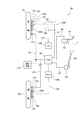
図1は、本発明の実施の形態に係る自動二輪車1の左側面図である。また、図2は、自動二輪車1の右側面図であり、図3は、車体フレーム2を制動構造と共に示す図である。
図1乃至図3に示すように、この自動二輪車1の車体フレーム2は、その前端部に配置されたヘッドパイプ11と、ヘッドパイプ11の上部左右から後下方に延びる左右一対のメインフレーム12と、ヘッドパイプ11の下部左右からメインフレーム12の下方を後下方に延びる左右一対のダウンフレーム13(図3参照)と、メインフレーム12の後部から後上方に延びる左右一対のリヤフレーム(シートレールとも言う)14(図3参照)と、メインフレーム12の後部から下方に延びる左右一対のピボットプレート15とを備えている。
車体フレーム2は、さらに、ピボットプレート56の上部から後上方に延びてリヤフレーム14にそれぞれ接続される左右一対の補強用リヤフレーム17(図3参照)と、メインフレーム12とダウンフレーム13間を架橋する複数本の補強フレーム18(図3参照)とを備えている。
Hereinafter, an embodiment of the present invention will be described with reference to the drawings. In the description, descriptions of directions such as front and rear, right and left and up and down are the same as directions relative to the vehicle body unless otherwise specified.
FIG. 1 is a left side view of a
As shown in FIGS. 1 to 3, the
The
ヘッドパイプ11は、前輪19を操舵する操舵装置20を支持している。操舵装置20は、図3に示すように、ヘッドパイプ11に回転自在に支持されたステアリングステム21と、ステアリングステム21の下部に固定された下側ブリッジ部材(ボトムブリッジとも言う)22および上部に固定された上側ブリッジ部材(トップブリッジとも言う)23と、上下のブリッジ部材22,23に支持された左右一対のフロントフォーク24と、上側ブリッジ部材23に取り付けられたハンドル25とを備え、運転者のハンドル操作によってフロントフォーク24下端部に支持された前輪19を左右に操向させる。
The
メインフレーム12は、内燃機関であるエンジン31、燃料タンク32及びこれら主要部品の周辺部品を支持するフレームであり、エンジン31は、メインフレーム12の下方、ダウンフレーム13の後方かつピボットプレート15の前方に支持される。これによって、エンジン31は、車体フレーム2の前後中央下部に懸架される。
このエンジン31のクランクケース31Aの左側後部には、図2に示すように、エンジン出力軸31Bが設けられる。このエンジン出力軸31Bと後輪26とは、ドライブチェーン(以下、チェーンと言う)34を介して動力伝達可能に連結され、このチェーン34を介してエンジン31の動力が後輪26に伝達される。
ピボットプレート15における上下中間部には、左右一対のスイングアーム35の前端部を回動自在に軸支するピボット軸36が貫通して支持される。このピボット軸36は、車幅方向に平行に配置され、スイングアーム35をピボット軸36を支点にして上下に揺動自在に支持する。このスイングアーム35と車体フレーム2との間には単一のリヤクッション37(図1参照)が介挿される。
The
As shown in FIG. 2, an
A
左右一対のリヤフレーム14は、運転者が着座する乗員用シート41と、同乗者が着座する乗員用シート42とを前後に間隔を空けて支持するとともに、乗員用シート42後方に後側リヤフェンダ43や後方灯火類44等を支持する。
運転者用の乗員用シート41の前方には、燃料タンク32が配置され、この燃料タンク32の下方にエンジン31が配置されている。なお、車体フレーム2のピボットプレート15以外の主要フレーム(ヘッドパイプ11、メインフレーム12、ダウンフレーム13、リヤフレーム14、補強用リヤフレーム17)は、鋼材等の金属材料からなる金属パイプで形成され、ピボットプレート15は、金属材料からなる板状部材で形成されている。
The pair of left and right rear frames 14 support an
A
図1及び図2に示すように、この自動二輪車1は、車体を覆う車体カウル(車体カバーとも言う)60を備えている。
車体カウル60は、車体の略全体を覆うフルカウリングタイプに構成されており、車体前部を覆うフロントカウル61と、このフロントカウル61に連設されて車体左右を覆う左右一対のサイドカウル62と、車体下方を覆うロアカウル63と、車体後部を覆う左右一対のリヤカウル64とを備えている。
フロントカウル61は、ヘッドパイプ11及びメインフレーム12の前方に設けられ、ヘッドライト66、ウインドスクリーン67及び左右一対のバックミラー68等が取り付けられる。
サイドカウル62は、フロントカウル61に連結され、車体フレーム2の前部左右やエンジン31の前部(シリンダ部31C)左右を覆う。ロアカウル63は、サイドカウル62の下部に連結され、エンジン31のクランクケース31A下方を覆う。
As shown in FIGS. 1 and 2, the
The
The
The
このエンジン31のシリンダ部31C後方には、エンジン吸気系が配置される。また、車体フレーム2の後下方かつ後輪26の側方(右側)には、図2に示すように、マフラー69が配置され、このマフラー69の前端とエンジン31のシリンダ部31Cとの間に排気管70が接続され、この排気管70とマフラー69とによってエンジン排気系が構成される。
なお、図中、符号71は、運転者が足を置く左右一対のメインステップであり、符号72は、前輪19の上方を覆うフロントフェンダである。
An engine intake system is disposed behind the
In the figure,
この自動二輪車1は、油圧式の制動装置80を備えている。
図4は、制動装置80を周辺構成とともに車体上方から見た図であり、図5は、制動装置80の回路構成を示す図である。
図4及び図5に示すように、制動装置80は、ハンドル25に取り付けられたブレーキ操作子としてのブレーキレバー81と、このブレーキレバー81の操作によってブレーキ液圧(油圧)を発生させるレバー側マスタシリンダ82と、メインステップ71近傍に取り付けられたブレーキ操作子としてのブレーキペダル83と、このブレーキペダル83の操作によりブレーキ液圧(油圧)を発生させるペダル側マスタシリンダ84と、ペダル側マスタシリンダ84にそれぞれ入力用ブレーキ配管である配管86,87で接続されたABSモジュレータ88と、このABSモジュレータ88に前輪出力用ブレーキ配管である配管91,92,107,109で接続された前輪用ブレーキ装置(フロントブレーキ装置)101と、ABSモジュレータ88に後輪出力用ブレーキ配管としての配管103〜105で接続された後輪用ブレーキ装置(リヤブレーキ装置)102とを備えている。
The
4 is a view of the
As shown in FIGS. 4 and 5, the
さらに、制動装置80は、後輪用ブレーキ装置102に接続される配管103の途中に設けられるプレッシャコントロールバルブ(以下、PCVと言う)106と、前輪用ブレーキ装置101及びABSモジュレータ88のそれぞれを接続する出力用ブレーキ配管としての配管107の途中に設けられるディレイバルブ(DV)108と、前輪19の回転速度(車輪速度)を検出する前輪車輪速センサ113と、後輪26の回転速度(車輪速度)を検出する後輪車輪速センサ116と、これら車輪速センサ113,116からの信号に基づいてABSモジュレータ88を制御する制御装置118とを備えている。
Further, the
ABSモジュレータ88は、制御装置118の制御の下、前輪用ブレーキ装置101及び後輪用ブレーキ装置102のブレーキ液圧を制御することによって各ブレーキ装置101,102の制動力を制御し、前輪19及び後輪26がロックするのを防止する制動力制御装置として機能する。
このABSモジュレータ88は、図3及び図4に示すように、略直方体の箱形状を有し、支持ステー88Aを介して車体フレーム2に取り付けられ、後輪26の前上部を覆う前側リヤフェンダ151の前方、かつ、リヤクッション37の後方であって、乗員用シート41下方、かつ、スイングアーム35上方に配置される。
このABSモジュレータ88は、電動モータ、この電動モータで駆動されるポンプ、このポンプに接続される複数のブレーキ液通路、これらのブレーキ液通路の途中に設けられた複数のソレノイドバルブ等を備えるため、比較的重量を有する重量部品である。この重量部品を該位置に配置することで、自動二輪車1の前端や後端に配置する場合に比して、自動二輪車1のマスの集中化を図ることができる。
Under the control of the
3 and 4, the
The
前輪用ブレーキ装置101は、油圧制動装置を構成する油圧ディスクブレーキであり、図1に示すように、前輪19の側方(右側方)に取り付けられて前輪19と一体に回転するブレーキディスク121と、このブレーキディスク121を挟んで制動させるブレーキキャリパ122とを備える。この自動二輪車1は、前輪19の片側(右側)だけに油圧ディスクブレーキを備えたシングルディスク式に構成されている。
ブレーキキャリパ122内には、図5に示すように、ブレーキディスク121にブレーキパッドを押し付けるピストンが移動自在に挿入されたシリンダ122a,122bが形成され、各シリンダ122a,122bには、配管92,109が接続される。
ここで、前輪用ブレーキ装置101に接続される配管92,109は、前輪19の操向に追従できるように、ゴムホース等の可撓性を有するブレーキホースが用いられる。これらブレーキホースの配管92,109は、車体フレーム2側に設けられた前側ブレーキ出力側ジョイント部200を介して車体フレーム2側に配索された金属パイプである配管91,107に接続される。
The front
In the
Here, the
後輪用ブレーキ装置102は、油圧制動装置を構成する油圧ディスクブレーキであり、後輪26の側方(右側方)に取り付けられて後輪26と一体的に回転するブレーキディスク124と、このブレーキディスク124を挟んで制動させるブレーキキャリパ125とを備え、ブレーキキャリパ125内には、ブレーキディスク124にブレーキパッドを押し付けるピストンが移動自在に挿入された単一のシリンダ125aが形成されている。
ここで、後輪用ブレーキ装置102のシリンダ125aに接続される配管103は、後輪の上下動に追従できるように、ゴムホース等の可撓性を有するブレーキホースが用いられる。
The rear-
Here, a flexible brake hose such as a rubber hose is used for the
PCV106は、後輪用ブレーキ装置102に接続される配管103のブレーキ液圧を制御する連動ブレーキ制御装置として機能し、このPCV106によって、ブレーキペダル83が操作された場合に、後輪用ブレーキ装置102の制動力を調整し、後輪用ブレーキ装置102の作動に連動させて前輪用ブレーキ装置101を作動させ、前後輪連動ブレーキを実行させる。
ディレイバルブ108は、前輪用ブレーキ装置101の作動タイミングを調整する前輪用ブレーキコントロール装置として機能し、この前輪用ブレーキコントロール装置によって、前後輪連動ブレーキを行う場合に前輪用ブレーキ装置101側へのブレーキ液圧の供給を、後輪用ブレーキ装置102側よりも遅らせる。
The
The
前輪車輪速センサ113は、前輪19の側方(右方)に取り付けられたパルサーリング114(図2参照)を用いて前輪速度を検出するセンサであり、この前輪車輪速センサ113から延びる配線131は、制御装置118及びABSモジュレータ88に接続され、このセンサ113の出力信号が制御装置118及びABSモジュレータ88に出力される。
後輪車輪速センサ116は、後輪26の側方(右側)に取り付けられたパルサーリング117(図2参照)を用いて後輪速度を検出するセンサであり、この後輪車輪速センサ116から延びる配線132は、制御装置118に接続され、このセンサ116の出力信号が制御装置118に出力される。
制御装置118は、前輪車輪速センサ113と後輪車輪速センサ116からの信号に基づいて前輪速度と後輪速度とを取得し、前輪速度と後輪速度との差に基づいて前後輪がスリップしないように前輪用ブレーキ装置101及び後輪用ブレーキ装置102を制御する。
The front
The rear
The
つまり、この自動二輪車1の制動装置80では、ブレーキペダル83が操作された場合、ペダル側マスタシリンダ84がブレーキペダルの操作に応じたブレーキ液圧を発生し、このブレーキ液圧が配管87を経由してABSモジュレータ88に供給される。
この場合、ABSモジュレータ88は、ABSモジュレータ88からのブレーキ液圧を、配管103に供給することにより、後輪用ブレーキ装置102を作動させるとともに、ABSモジュレータ88からのブレーキ液圧を、柔軟性ブレーキホースである配管107に供給することにより、ディレイバルブ108を介して前輪用ブレーキ装置101のシリンダ122bにブレーキ液圧を供給し、前輪用ブレーキ装置101を作動させる。
すなわち、前輪用ブレーキ装置101と後輪用ブレーキ装置102とを同時に作動させる前後連動ブレーキが実行される。
このブレーキの際には、制御装置118は、前輪速度と後輪速度とを監視し、前輪19及び後輪26がロックしないようにABSモジュレータ88からのブレーキ油圧を制御する。
That is, in the
In this case, the
That is, the front-rear interlocking brake that simultaneously activates the front
During this braking, the
一方、ブレーキレバー81が操作された場合には、レバー側マスタシリンダ82がブレーキレバー81の操作に応じたブレーキ液圧を発生し、このブレーキ液圧が配管86を経由してABSモジュレータ88に供給される。
この場合、ABSモジュレータ88は、ABSモジュレータ88からのブレーキ液圧を金属パイプである配管91に供給することにより、ブレーキ液圧を、柔軟性ブレーキホースである配管92を介して前輪用ブレーキ装置101のシリンダ122aに供給し、前輪用ブレーキ装置101を作動させる。
このブレーキレバー81操作時に前後連動ブレーキを行う場合には、ABSモジュレータ88は、更に、ABSモジュレータ88で調整されたブレーキ液圧を、配管103に供給し、後輪用ブレーキ装置102を作動させる。
このブレーキの際にも、制御装置118は、前輪速度と後輪速度とを監視し、前輪19及び後輪26がロックしないようにABSモジュレータ88からのブレーキ油圧を制御する。
On the other hand, when the
In this case, the
When the front / rear interlocking brake is performed when the
Also during the braking, the
図6は、車体後部を右側から見た図であり、図7は上方から見た図である。
図6及び図7に示すように、後輪用ブレーキ装置102に接続される可撓性ゴムホースからなる配管103は、左右一対のスイングアーム35のうち、後輪用ブレーキ装置102が配設される側(右側)のスイングアーム35の上面35Tに配索される。
この配管103が接続される後輪用ブレーキ装置102のブレーキキャリパ125は、右側のスイングアーム35の上方かつ後輪軸26Aの前方に配置されており、配管103が接続されるジョイント部125Aは、ブレーキキャリパ125から前上方に向けて突出する配置とされる。
6 is a view of the rear part of the vehicle body as seen from the right side, and FIG. 7 is a view as seen from above.
As shown in FIGS. 6 and 7, the
The
この配管103の一端(後端)35Rは、ジョイント部125Aに対し、配管連結部材126によって連結され、このジョイント部125Aから前下がりに傾斜して可動配管部として機能する前下がり配管部103Aを形成するようにスイングアーム上面35Tに向けて延びた後、スイングアーム上面35Tの前後中間位置に設けられたクランプ部材161と、スイングアーム上面35Tの前側に設けられた係止部164とによって、スイングアーム35に沿って前後方向に延びる直線配管部103Bを形成するようにスイングアーム上面35Tに支持される。
ここで、配管103の一端35Rは、配管連結部材125Bの軸線LF(図6参照)を中心に回動自在に連結されるとともに、この一端35R側の前下がり配管部103Aが、配管103自体の柔軟性で可動自在な可動配管部となっている。このため、ブレーキキャリパ125が片押し式でブレーキ作動等でジョイント部125Aが車幅方向外側に移動した場合や、チェーンアジャスト(スイングアーム35に対する後輪軸26Aの前後位置を調整)したために、ジョイント部125Aが相対移動した場合に、配管103の一端35R側の向きを追従させることが可能になっている。
One end (rear end) 35R of the
Here, one
但し、配管103の一端35Rが車幅方向外側に自由に回動したとすると、配管103の前下がり配管部103Aが、車幅方向外側に大きく張り出してしまうおそれがある。このため、本構成では、ブレーキキャリパ125側に、配管103の車幅方向外側への回動限界を規定する回り止め部材125C(図6参照)を設け、この回り止め部材125Cによって、配管103が車幅方向外側に張り出す位置までは回転できないようになっている。
However, if the one
上記クランプ部材161は、ねじ等の締結部材によってスイングアーム上面35Tに固定される筒状の配管保持部品であり、本構成では、配管103に被せられた配管保護部品であるナイロンプロテクタ163を保持する。
このナイロンプロテクタ163は、ナイロン製であるため容易に曲がらない剛体の筒部品であり、直線状に延び、配管103の前下がり配管部103Aは覆わず、配管103の直線配管部103Bだけを覆う。つまり、配管103は、ナイロンプロテクタ163によって直線状に保持される。
このナイロンプロテクタ163は、前後方向で、後輪用ブレーキ装置102の前方から後輪26の前方まで直線状に延びる長さに形成され、より具体的には、側面視で、後輪26のホイールリム26R近傍から後輪26の接地面(トレッド面とも言う)26S前方まで延びる長さに形成される。このように、ナイロンプロテクタ163が後輪26のホイールリム26R近傍から接地面26S前方まで延在して配置すれば、後輪26側からの飛散物(水や泥等)が配管103に付着することを効率よく回避できる。
The
The
The
係止部164は、溶接等によってスイングアーム上面35Tの基端側(軸支側)に固定され、配管103及び配管103を覆うナイロンプロテクタ163を着脱自在に保持する係止部品である。
この係止部164は、金属製の針金部材を曲げて形成され、スイングアーム35に固定される基端側を基準に、車幅方向外側に延出し、係止部164の車幅方向外側端部が配管103の直径より小さい所定の距離でスイングアーム上面35Tと離間して開放する開放部164B(図7参照)を有している。
また、開放部164Bより車幅方向内側には、上方に向かって凸の円弧状に湾曲する引っ掛け部164Aを有しており、この引っ掛け部164Aに配管103及びナイロンプロテクタ163を通過させることにより、係止している。
The locking
The locking
In addition, on the inner side in the vehicle width direction from the
引っ掛け部164Aと配管103との当接面は、ナイロンプロテクタ163により保護されている。
この配管103は、ナイロンプロテクタ163よりも前方では、上方向きに湾曲する湾曲配管部103Cを形成するように配索されており、この湾曲配管部103Cを経由して、スイングアーム35上方に配置されたPCV106に接続される。
スイングアーム35の揺動に伴い、湾曲配管部103Cが撓むことにより、配管103をスイングアーム35に追従させることができるため、スイングアーム上面35Tに配置される配管103について、常にスイングアーム上面35Tに対して一定の一に配索されることになり、コンパクト化を図ることができる。
なお、チェーン34の伸び調整等の後輪軸26Aの位置を調整する場合、クランプ部材161及び係止部164は、配管103の長手方向の相対移動を許容する。
A contact surface between the
This
Since the
When adjusting the position of the
このように、配管103は、スイングアーム35の自由端側(後端側)でブレーキキャリパ125から前下がりに傾斜する前下がり配管部103Aと、スイングアーム上面35Tに沿って延びる直線配管部103Bと、スイングアーム35の軸支端側(前端側)で上方に湾曲する湾曲配管部103Cとを有するように配索され、直線配管部103Bがナイロンプロテクタ163で保護される。
この構成では、前下がり配管部103Aが自由に可動できるので、ブレーキキャリパ125が片押し式でブレーキ作動時にジョイント部125Aが車幅方向内側に移動した場合や、チェーンアジャストした場合に、配管103を可動させて追従させることができる。
また、スイングアーム35の軸支端側(前端側)に湾曲配管部103Cを設けたため、スイングアーム35の上下の揺動に合わせて配管103を追従させ易くすることができる。
As described above, the
In this configuration, the front-falling
Further, since the
本構成の自動二輪車1では、上記配管103の外観露出を回避するために後輪26の前上部を覆う前側リヤフェンダ151を、配管103を覆うカバー形状に形成している。
この前側リヤフェンダ151は、合成樹脂製のカバー部品であり、図6及び図7に示すように、後輪26の接地面26Sに対向して後輪26からの水や泥が車体側に付着するのを遮断する後輪カバー部152と、この後輪カバー部152から車幅方向右側に膨出して右側のスイングアーム35上方の配管103を覆う配管カバー部として機能する右側カバー部154と、この後輪カバー部152から車幅方向左側に膨出する左側カバー部156とを一体に有している。
この前側リヤフェンダ151は、右側カバー部154を右側のスイングアーム35に取り付け、左側カバー部156を左側のスイングアーム35に取り付けることによって、左右のスイングアーム35に取り付けられ、スイングアーム35と一体的に上下に揺動する。
In the
The front
The front
図6に示すように、後輪カバー部152は、スイングアーム35上方にて、後輪26の接地面26Sと補強用リヤフレーム17との間を後輪26の接地面26Sに沿って後上方へ延在する側面視三角形状を有し、スイングアーム35上方に位置する後輪26の接地面26Sを上方から左右に渡って覆う。
図6に示すように、この後輪カバー部152は、側面視で、ピボットプレート15後方から後輪26の前上部に渡って延在するので、後輪26側からの飛散物(水や泥等)がスイングアーム35上方に露出する車両部品(ABSモジュレータ88、リヤクッション37)にかかり難くする。
As shown in FIG. 6, the rear
As shown in FIG. 6, the rear
図7に示すように、右側カバー部154は、後輪カバー部152の右側面152Aから車幅方向外側である右側に膨出し、スイングアーム35の車幅方向外側面35Aと車幅方向で同じ位置をスイングアーム35に沿って後方に延びる側壁154Aと、この側壁154Aの上縁と後輪カバー部152の右側面152Aとの間に渡って延在する上板154Bとを有する断面L形状に形成されている。
この側壁154Aは、側面視で(図6参照)、スイングアーム上面35Tに配置されるナイロンプロテクタ163の側方から、ブレーキキャリパ125のジョイント部125Aまで前後方向に延び、ジョイント部125Aとナイロンプロテクタ163との間で配管103の車幅方向外側を覆う。
As shown in FIG. 7, the
The
より具体的には、この側壁154Aの下縁154A1は、スイングアーム上面35Tに沿って直線的に延びる形状を有し、この形状によりスイングアーム35に近接して配置でき、スイングアーム上面35Tの配管103を車幅方向外側から確実に覆うことができる。
また、側壁154Aの上縁154A2は、右側カバー部154と後輪カバー部152の後縁152Bとが側面視で重なる位置PA(図6参照)までは後上方に延びて上下幅を徐々に大きくし、後縁152Bと重なる位置PAから後方では後下方に延びて上下幅を徐々に狭くする形状に形成されているので、配管103を車幅方向外側から覆いつつ、後方ほど軽量化することができる。
More specifically, the lower edge 154A1 of the
Further, the upper edge 154A2 of the
また、右側カバー部154の上板154Bは、側壁154Aの上縁154A2に沿って前後方向に延び、上記位置PAより前方では後上方に延び、上記位置PAより後方では後下方に延び、これによって、配管103の上方を覆う。
この上板154Bは、図7に示すように、上記位置PAより前方では、後輪カバー部152の右側面152Aと右側カバー部154の側壁154Aとの間の隙間を埋めるように車幅方向に延在し、配管103の上方を確実に覆う。
一方、上記位置PAより後方では、上板154Bの車幅方向内側の外縁154Rが、後方へ行くに従って車幅方向外側へ拡がる形状に形成され、これによって、後方に行くに従って側壁154Aとの間の幅が徐々に狭くなり、後方にてスイングアーム上面35Tを上方に露出させる。
Further, the
As shown in FIG. 7, the
On the other hand, on the rear side of the position PA, the
すなわち、後輪カバー部152の外縁152Rと右側カバー部154の外縁154Rとによって、スイングアーム上面35Tを露出させる前方に凸の切り欠き部155が形成される。
図7に示すように、この切り欠き部155は、配管103の前下がり配管部103Aが通る開口通路として機能しており、前下がり配管部103Aは、スイングアーム上面35Tからこの切り欠き部155を通って、スイングアーム上面35Tから離間し、後輪用ブレーキ装置102に接続される。この場合、配管103を左右に大きく迂回させる必要がないので、配管103と右側カバー部154との干渉を抑制しつつ配管長を短くすることができる。
In other words, the outer edge 152R of the rear
As shown in FIG. 7, the
図6に示すように、この右側カバー部154は、右側のスイングアーム35に設けられた支持ステー165に締結部材(例えば、締結ねじ)166で締結され、これによって、右側のスイングアーム35に固定される。
この支持ステー165は、前後に間隔を空けて配置される前後一対の支持ステー165A,165Bを有し、前側の支持ステー165Aは、側面視で、ナイロンプロテクタ163前端近傍を上方に延び、図7に示すように、上面視では、スイングアーム35の車幅方向外側面35Aと車幅方向で略同じ位置に設けられる。
また、後側の支持ステー165Bは、図6に示すように、側面視で、ブレーキキャリパ125の前端近傍を上方に延び、図7に示すように、上面視では、スイングアーム35の車幅方向外側面35Aと車幅方向で略同じ位置に設けられる。
そして、これら前後一対の支持ステー165A,165Bの外側(右側)に、右側カバー部154の側壁154Aを配置し、車幅方向外側(右側)から前後一対の締結部材166を貫通させて支持ステー165A,165Bに各々締結することによって、右側カバー部154がスイングアーム35に固定される。
この場合、前後一対の支持ステー165A,165Bの位置が、図6に示すように、右側カバー部154の前端と後端の位置に相当しているので、前後に長い右側カバー部154を効率よく支持することができる。
As shown in FIG. 6, the
The
Further, as shown in FIG. 6, the
Then, the
In this case, since the positions of the pair of front and rear support stays 165A and 165B correspond to the positions of the front end and the rear end of the
また、本構成では、前後一対の支持ステー165A,165Bを、スイングアーム35の車幅方向外側面35Aと車幅方向で略同じ位置に設けたので、この支持ステー165A,165Bに取り付けられた右側カバー部154の側壁154Aについても、スイングアーム35の車幅方向外側面35Aと車幅方向で略同じ位置に設けることができる(図7参照)。これによって、右側カバー部154の車幅方向外側面とスイングアーム35の車幅方向外側面35Aとを略同一平面に揃えることができる。
この構成によれば、右側カバー部154の側壁154Aとスイングアーム35の車幅方向外側面35Aとが連続するので、右側カバー部154によってスイングアーム上面35Tの配置部品(配管103)の車幅方向外側を確実に覆うことができるとともに、上下に太いスイングアームを模した外観デザインにすることができる。
Further, in this configuration, the pair of front and rear support stays 165A and 165B are provided at substantially the same position in the vehicle width direction as the vehicle width direction
According to this configuration, since the
次に左側カバー部156について説明する。
左側カバー部156は、図7に示すように、後輪カバー部152の左側面152Cから車幅方向外側である左側に膨出し、左側のスイングアーム35の車幅方向外側面35Aと車幅方向で同じ位置をスイングアーム35に沿って後方に延びる側壁156Aと、この側壁156Aの上縁と後輪カバー部152の左側面152Cとの間を覆うと共に、スイングアーム上面35Tを覆うように後方に延びる上板156Bとを有する断面L形状に形成されている。
図1に示すように、側壁156Aは、上方に凸の湾曲形状を有しており、その前下部156AFが、スイングアーム35の車幅方向外側面35Aと重なり、締結部材(例えば、締結ねじ)167によってスイングアーム35に固定される。また、側壁156Aの後下部156ARは、スイングアーム35の後端部近傍まで延出し、スイングアーム35の後端上面から上方に延びる支持ステー165Cに締結部材168によって固定される。
Next, the
As shown in FIG. 7, the
As shown in FIG. 1, the
図1に示すように、この左側カバー部156は、前下部156AFと後下部156ARとの間の部分が、スイングアーム上面35Tよりも上方位置で後輪26左側に配置されるチェーン34の車幅方向外側を覆うように延び、チェーンガードとして機能する。しかも、この左側カバー部156は、上方に凸の湾曲形状を有して後方に行くに従って徐々に上下幅を小さくする形状に形成されるので、左側カバー部156を、スイングアーム35を補強する補強フレームを模した外観デザインにすることができる。
なお、図7中、符号181は、車両が具備する電気系部品の配線(電線)をまとめたメインハーネスである。このメインハーネス181は、車体フレーム2の左側(左側のメインフレーム12、左側のリヤフレーム14又は補強用リヤフレーム17)に沿わせて車両左側に配設される。本構成では、図3及び図4に示すように、ブレーキ配管類(配管86,87,91,103,107等)が、車両右側のメインフレーム12の車幅方向内側に配置されており、これによって、電気系のメインハーネス181と、ブレーキ系の配管類とは左右に振り分けて配置するように構成されている。
As shown in FIG. 1, the
In FIG. 7,
本実施の形態では、図6に示すように、後輪26の前方および上方の一部を覆う前側リヤフェンダ151を備え、この前側リヤフェンダ151は、スイングアーム35に設けられ、スイングアーム上面35Tに配索される配管103を車幅方向外側から覆う配管カバー部として機能する右側カバー部154を有するカバー形状に形成されるので、スイングアーム上面35Tに配設されるブレーキ配管である配管103を、部品点数を削減しつつ保護することができる。
In the present embodiment, as shown in FIG. 6, a front
また、本構成では、図6に示すように、後輪車輪速センサ116から延びる配線132についても、右側のスイングアーム上面35Tに配索されており、この配線132についても、前側リヤフェンダ151の右側カバー部154によって車幅方向外側が覆われる。この配線132をスイングアーム上面35Tに保持する保持部材は、配管103をスイングアーム35に保持するクランプ部材161が兼用しており、部品点数の削減を図っている。
この構成によれば、右側カバー部154を、後輪車輪速センサ116の配線132を保護する保護部品に兼用でき、部品点数を増やすことなく配線132を保護できる。
Further, in this configuration, as shown in FIG. 6, the
According to this configuration, the
また、本構成では、前側リヤフェンダ151が、後輪26の接地面26Sに対抗する後輪カバー部152と右側カバー部154とを備え、右側カバー部154の車幅方向外側面が、スイングアーム35の車幅方向外側面35Aと車幅方向で略同じ位置に形成されるとともに、前後方向で、後輪26の前方から後輪用ブレーキ装置102の前方まで配管103の車幅方向外側を覆うので、配管103の保護を配管103が露出する領域で行うことができるとともに、右側カバー部154とスイングアーム35との一体感を創出し、スイングアームを太くした複雑な形状に見せることができ、外観性が向上する。
Further, in this configuration, the front
また、スイングアーム35の車幅方向外側端部に、上方に延出して前側リヤフェンダ151を支持する支持ステー165を設け、支持ステー165内側のスイングアーム上面35Tに配管103を配索し、この配管103の車幅方向内側のスイングアーム上面35Tに、車幅方向外側に開放して配管103を係止する係止部164を設けたので、簡易な構成で配管103を係止することができ、生産性及びコスト低減が可能となる。
また、この構成では、係止部164から配管103が抜ける側に、支持ステー165が位置するので、支持ステー165を、係止部164からの配管103の抜け止めとして兼用させることができ、部品点数をより削減し、生産性の向上及びコスト低減を図ることができる。
Further, a
Further, in this configuration, since the
また、後輪カバー部152の外縁152Rと右側カバー部154の外縁154Rとが、上面視で前方に凸の切り欠き部155を形成し、スイングアーム上面35Tの配管103が、切り欠き部155を通ってスイングアーム上面35Tから離間するので、後輪用ブレーキ装置102とスイングアーム35とが相対的に変位しても、切り欠き部155により配管103と前側リヤフェンダ151との干渉を抑制しつつ、配管103を保護することができる。
Further, the outer edge 152R of the rear
また、図7に示すように、本構成では、後輪用ブレーキ装置102が、スイングアーム35の上方かつ後輪軸26Aの前方に配置され、右側カバー部154が、後輪用ブレーキ装置102と配管103とのジョイント部125Aと前後方向で重なるので、後輪用ブレーキ装置102に連結される配管103を覆う右側カバー部154の領域を可及的に少なくすることができ、右側カバー部154の軽量化を図ることができる。
Further, as shown in FIG. 7, in this configuration, the rear
次に、ペダル側マスタシリンダ84のリザーブタンク171について説明する。
本構成では、図6に示すように、ペダル側マスタシリンダ84が、ブレーキペダル83近傍、より具体的には、右側のメインステップ71の近傍後方、かつ、右側のスイングアーム35の車幅方向外側に配置されている。このペダル側マスタシリンダ84には、右側のスイングアーム上面35Tの上方で車幅方向内側に突出するジョイント部84Aが設けられ、このジョイント部84Aに配管172を介してリザーブタンク171が接続されている。
図6に示すように、リザーブタンク171を、右側のスイングアーム35と補強用リヤフレーム17との間に配置しようとした場合、本構成の前側リヤフェンダ151は、配管103の車幅方向外側を覆う幅広形状を有するので、リザーブタンク171が車幅方向外側に張り出し易くなる。
Next, the
In this configuration, as shown in FIG. 6, the pedal-
As shown in FIG. 6, when the
そこで、本構成のリザーブタンク171は、ブレーキオイルを適正量貯留できる容積を有した直方体形状であって、図6に示すように、車両高さ方向の長さである上下長αを、車両前後方向の長さである前後長βより長くするとともに、図4に示すように、前後長βよりも車幅方向の長さである幅長γを短くすることによって、上下長α>前後長β>幅長γ、に形成している。
この場合、リザーブタンク171の幅長γを最小にしたので、リザーブタンク171を車幅方向外側に張り出し難くできる。
Therefore, the
In this case, since the width γ of the
また、リザーブタンク171の上下長αを最大にしたので、前後寸法が比較的狭いスペースにリザーブタンク171を配置し易くなる。
本構成では、図6に示すように、右側のスイングアーム35と補強用リヤフレーム17との間の上下寸法が比較的長いスペースSPに、リザーブタンク171を配置するため、リザーブタンク171の上下長αを最大にしても上記スペースSPに配置することが可能である。
しかも、このリザーブタンク171は、補強用リヤフレーム17に設けられた支持ステー175に固定されることによって、上記スペースSP内で、補強用リヤフレーム17に近接する上方側かつ前方側であって、前側リヤフェンダ151の車幅方向外側に配置される。この配置により、図6では、リザーブタンク171が、前側リヤフェンダ151の側面視で上方に位置するが、後輪26に荷重が作用してスイングアーム35が上方に揺動したときに右側カバー部154と側面視で重なる。
In addition, since the vertical length α of the
In this configuration, as shown in FIG. 6, since the
In addition, the
すなわち、本構成では、リザーブタンク171を、前側リヤフェンダ151の車幅方向外側で、スイングアーム35が上方に揺動したときに前側リヤフェンダ151と側面視で重なる位置に配置している。
この構成によれば、前側リヤフェンダ151が配管103の車幅方向外側を覆う形状であっても、リザーブタンク171を車幅方向外側に張り出さずに配置できるとともに、リザーブタンク171を、スイングアーム35の前上方に配設される後輪用ブレーキ関連装置(ABSモジュレータ88等)に集約させて配置でき、全体のシステムをコンパクト化できる。
また、後輪26に荷重が作用しない場合は、リザーブタンク171と、右側カバー部154を含む前側リヤフェンダ151との間の隙間が広い状態となるので、リザーブタンク171の着脱作業といった各種作業を容易に行うことが可能である。
That is, in this configuration, the
According to this configuration, even if the front
In addition, when no load is applied to the
上述した実施形態は、あくまでも本発明の一態様を示すものであり、本発明の主旨を逸脱しない範囲で任意に変形及び応用が可能である。
例えば、上記実施形態では、図1に示す自動二輪車1の制動装置に本発明を適用する場合について説明したが、これに限らず、鞍乗り型車両の制動装置に本発明を広く適用することができる。なお、鞍乗り型車両とは、車体に跨って乗車する車両全般を含み、自動二輪車(原動機付き自転車も含む)のみならず、ATV(不整地走行車両)に分類される三輪車両や四輪車両を含む車両である。
The above-described embodiment is merely an aspect of the present invention, and can be arbitrarily modified and applied without departing from the gist of the present invention.
For example, in the above embodiment, the case where the present invention is applied to the braking device of the
1 自動二輪車(鞍乗り型車両)
2 車体フレーム
26 後輪
26A 後輪軸
35 スイングアーム
81 ブレーキレバー(ブレーキ操作子)
84 ペダル側マスタシリンダ
102 後輪用ブレーキ装置
103 配管(ブレーキ配管)
116 後輪車輪速センサ
125A ジョイント部
132 配線
151 前側リヤフェンダ(カバー)
152 後輪カバー部
154 右側カバー部(配管カバー部)
155 切り欠き部
171 リザーブタンク
1 Motorcycle (saddle-ride type vehicle)
2
84 Pedal
116 Rear
152
155
Claims (10)
車体フレーム(2)に揺動可能に懸架されるスイングアーム(35)と、
スイングアーム(35)の自由端側に回転自在に支持される後輪(26)と、
スイングアーム(35)の自由端側に配置される後輪用ブレーキ装置(102)と、
スイングアーム(35)の軸支部近傍で車体フレーム(2)に固定されるブレーキ操作子(81)と、
スイングアーム(35)上面に配策され、ブレーキ操作子(81)のブレーキ操作を後輪用ブレーキ装置(102)に伝達するブレーキ配管(103)とを備える鞍乗り型車両の制動装置において、
前記後輪(26)の前方および上方の一部を覆うカバー(151)を備え、このカバー(151)は、前記スイングアーム(35)に設けられ、前記ブレーキ配管(103)を車幅方向外側から覆う配管カバー部(154)を有するカバー形状に形成され、
前記カバー(151)は、前記後輪(26)を挟んで前記後輪用ブレーキ装置(102)と逆側に設けられるチェーン(34)の車幅方向外側を覆うチェーンカバー部(156)を備えることを特徴とする鞍乗り型車両の制動装置。 Body frame (2),
A swing arm (35) suspended swingably on the vehicle body frame (2);
A rear wheel (26) rotatably supported on the free end side of the swing arm (35);
A rear wheel brake device (102) disposed on the free end side of the swing arm (35);
A brake operator (81) fixed to the vehicle body frame (2) in the vicinity of the shaft support portion of the swing arm (35);
In a braking device for a saddle-ride type vehicle provided with a brake pipe (103) arranged on the upper surface of the swing arm (35) and transmitting a brake operation of the brake operation element (81) to the brake device for rear wheel (102),
A cover (151) that covers a part of the front and upper sides of the rear wheel (26) is provided. The cover (151) is provided on the swing arm (35), and the brake pipe (103) is disposed outside in the vehicle width direction. Formed into a cover shape having a piping cover portion (154) covering from
The cover (151) includes a chain cover portion (156) that covers the outer side in the vehicle width direction of the chain (34) provided on the opposite side of the rear wheel brake device (102) across the rear wheel (26). A braking device for a saddle-ride type vehicle.
車体フレーム(2)に揺動可能に懸架されるスイングアーム(35)と、 A swing arm (35) suspended swingably on the vehicle body frame (2);
スイングアーム(35)の自由端側に回転自在に支持される後輪(26)と、 A rear wheel (26) rotatably supported on the free end side of the swing arm (35);
スイングアーム(35)の自由端側に配置される後輪用ブレーキ装置(102)と、 A rear wheel brake device (102) disposed on the free end side of the swing arm (35);
スイングアーム(35)の軸支部近傍で車体フレーム(2)に固定されるブレーキ操作子(81)と、 A brake operator (81) fixed to the vehicle body frame (2) in the vicinity of the shaft support portion of the swing arm (35);
スイングアーム(35)上面に配策され、ブレーキ操作子(81)のブレーキ操作を後輪用ブレーキ装置(102)に伝達するブレーキ配管(103)とを備える鞍乗り型車両の制動装置において、 In a braking device for a saddle-ride type vehicle provided with a brake pipe (103) arranged on the upper surface of the swing arm (35) and transmitting a brake operation of the brake operation element (81) to the brake device for rear wheel (102),
前記後輪(26)の前方および上方の一部を覆うカバー(151)を備え、このカバー(151)は、前記スイングアーム(35)に設けられ、前記ブレーキ配管(103)を車幅方向外側から覆う配管カバー部(154)を有するカバー形状に形成され、 A cover (151) that covers a part of the front and upper sides of the rear wheel (26) is provided. The cover (151) is provided on the swing arm (35), and the brake pipe (103) is disposed outside in the vehicle width direction. Formed into a cover shape having a piping cover portion (154) covering from
前記カバー(151)は、前記後輪(26)の接地面に対向する後輪カバー部(152)と前記配管カバー部(154)とを備え、 The cover (151) includes a rear wheel cover part (152) facing the grounding surface of the rear wheel (26) and the pipe cover part (154),
前記配管カバー部(154)の車幅方向外側面は、前記スイングアーム(35)の車幅方向外側面と車幅方向で略同じ位置に形成され、The outer surface in the vehicle width direction of the pipe cover portion (154) is formed at substantially the same position in the vehicle width direction as the outer surface in the vehicle width direction of the swing arm (35),
前記スイングアーム(35)に、上方に延出して前記カバーを支持する支持ステー(165)を設け、The swing arm (35) is provided with a support stay (165) extending upward to support the cover,
前記支持ステー(165)は、前後に間隔を空けて配置される前側支持ステー(165A)と、後側支持ステー(165B)とを備え、 The support stay (165) includes a front support stay (165A) and a rear support stay (165B) that are spaced apart from each other in the front-rear direction.
前記ブレーキ配管(103)は、側面視で、前記後側支持ステー(165B)よりも前方で、前記カバー(151)の前端よりも後方側から外側に露出するように設けられることを特徴とする鞍乗り型車両の制動装置。The brake pipe (103) is provided in front of the rear support stay (165B) in a side view so as to be exposed to the outside from the rear side of the front end of the cover (151). Braking device for saddle riding type vehicles.
前記支持ステー(165)内側の前記スイングアーム(35)上面に前記ブレーキ配管(103)を配索し、
前記ブレーキ配管(103)の車幅方向内側のスイングアーム(35)上面に、車幅方向外側に開放し、前記ブレーキ配管(103)を係止する係止部(164)を設けたことを特徴とする請求項1に記載の鞍乗り型車両の制動装置。 Wherein the swing arm (35), a support stay (165) is provided for supporting the cover extends upwardly,
The brake pipe (103) is routed on the upper surface of the swing arm (35) inside the support stay (165),
A locking portion (164) that opens to the outside in the vehicle width direction and locks the brake piping (103) is provided on the upper surface of the swing arm (35) on the vehicle width direction inside of the brake piping (103). The braking device for a saddle-ride type vehicle according to claim 1 .
前記配管カバー部(154)が、前記リヤブレーキ装置(102)と前記ブレーキ配管(103)とのジョイント部(125A)と前後方向で重なることを特徴とする請求項1乃至4のいずれかに記載の鞍乗り型車両の制動装置。 The rear brake device (102) is disposed above the swing arm (35) and in front of the rear wheel shaft (26A),
The said piping cover part (154) overlaps with the joint part (125A) of the said rear brake device (102) and the said brake piping (103) in the front-back direction. Brake system for saddle-ride type vehicles.
この車輪速センサ(116)から延びる配線(132)を前記配管カバー部(154)で覆うことを特徴とする請求項1乃至5のいずれかに記載の鞍乗り型車両の制動装置。 A wheel speed sensor (116) for detecting the rotational speed of the rear wheel (26);
The braking device for a saddle-ride type vehicle according to any one of claims 1 to 5, wherein a wiring (132) extending from the wheel speed sensor (116) is covered with the pipe cover portion (154).
前記支持ステー(165)は、前後に間隔を空けて配置される前側支持ステー(165A)と、後側支持ステー(165B)とを備え、 The support stay (165) includes a front support stay (165A) and a rear support stay (165B) that are spaced apart from each other in the front-rear direction.
前記ブレーキ配管(103)は、側面視で、前記前側支持ステー(165A)よりも前方で、前記カバー(151)の前端よりも後方側から外側に露出するように設けられることを特徴とする請求項1又は3に記載の鞍乗り型車両の制動装置。 The brake pipe (103) is provided in front of the front support stay (165A) in a side view so as to be exposed to the outside from the rear side of the front end of the cover (151). Item 4. The braking device for a saddle type vehicle according to item 1 or 3.
前記ジョイント部(125A)には、前記ブレーキ配管(103)が連結される配管連結部材(126)が設けられ、前記配管連結部材(125B)の軸線(LF)は車両前上方に傾斜し、 The joint part (125A) is provided with a pipe connecting member (126) to which the brake pipe (103) is connected, and the axis (LF) of the pipe connecting member (125B) is inclined upward in the front of the vehicle,
前記ブレーキ配管(103)は、前記配管連結部材(126)の軸線(LF)を中心に回動自在に連結されるとともに、前記配管連結部材(125B)から前下がりに延びる前下がり配管部(103A)を備えることを特徴とする請求項1乃至9のいずれかに記載の鞍乗り型車両の制動装置。 The brake pipe (103) is pivotally connected around the axis (LF) of the pipe connecting member (126) and extends forwardly downward from the pipe connecting member (125B) (103A). The braking device for a saddle-ride type vehicle according to any one of claims 1 to 9.
Priority Applications (4)
| Application Number | Priority Date | Filing Date | Title |
|---|---|---|---|
| JP2010064199A JP5507300B2 (en) | 2010-03-19 | 2010-03-19 | Braking device for saddle-ride type vehicles |
| KR1020110021006A KR101260588B1 (en) | 2010-03-19 | 2011-03-09 | Brake device of saddle type vehicle |
| ZA2011/02007A ZA201102007B (en) | 2010-03-19 | 2011-03-16 | Braking device of saddle-ride type vehicle |
| BRPI1101058A BRPI1101058B8 (en) | 2010-03-19 | 2011-03-17 | MOUNTED DRIVING TYPE VEHICLE BRAKE DEVICE |
Applications Claiming Priority (1)
| Application Number | Priority Date | Filing Date | Title |
|---|---|---|---|
| JP2010064199A JP5507300B2 (en) | 2010-03-19 | 2010-03-19 | Braking device for saddle-ride type vehicles |
Publications (3)
| Publication Number | Publication Date |
|---|---|
| JP2011195024A JP2011195024A (en) | 2011-10-06 |
| JP2011195024A5 JP2011195024A5 (en) | 2013-04-25 |
| JP5507300B2 true JP5507300B2 (en) | 2014-05-28 |
Family
ID=44873758
Family Applications (1)
| Application Number | Title | Priority Date | Filing Date |
|---|---|---|---|
| JP2010064199A Active JP5507300B2 (en) | 2010-03-19 | 2010-03-19 | Braking device for saddle-ride type vehicles |
Country Status (4)
| Country | Link |
|---|---|
| JP (1) | JP5507300B2 (en) |
| KR (1) | KR101260588B1 (en) |
| BR (1) | BRPI1101058B8 (en) |
| ZA (1) | ZA201102007B (en) |
Families Citing this family (19)
| Publication number | Priority date | Publication date | Assignee | Title |
|---|---|---|---|---|
| JP5941813B2 (en) * | 2012-09-28 | 2016-06-29 | 本田技研工業株式会社 | Straddle-type electric vehicle |
| JP6215540B2 (en) * | 2013-02-25 | 2017-10-18 | 本田技研工業株式会社 | Accessory socket arrangement structure for saddle-ride type vehicles |
| KR101779278B1 (en) * | 2013-03-28 | 2017-09-18 | 혼다 기켄 고교 가부시키가이샤 | Vehicle wheel speed sensor protection structure |
| JP6165012B2 (en) * | 2013-09-30 | 2017-07-19 | 本田技研工業株式会社 | Interlocking brake parts arrangement structure for saddle-ride type vehicles |
| JP6368231B2 (en) * | 2014-12-10 | 2018-08-01 | 川崎重工業株式会社 | Saddle riding vehicle |
| JP6220366B2 (en) * | 2015-07-29 | 2017-10-25 | 本田技研工業株式会社 | Saddle riding vehicle |
| JP6268134B2 (en) * | 2015-09-08 | 2018-01-24 | 本田技研工業株式会社 | Fender structure of saddle riding type vehicle |
| EP3409571B1 (en) * | 2016-01-28 | 2020-01-22 | Yamaha Hatsudoki Kabushiki Kaisha | Saddled vehicle equipped with combined brake system |
| CA2961468A1 (en) | 2016-03-28 | 2017-09-28 | Honda Motor Co., Ltd. | Saddle-riding-type vehicle cable support structure |
| JP6605709B2 (en) * | 2016-03-29 | 2019-11-13 | 本田技研工業株式会社 | Saddle riding |
| JP6200991B1 (en) * | 2016-03-31 | 2017-09-20 | 本田技研工業株式会社 | Electric vehicle drive device |
| ES2679645B2 (en) * | 2017-02-23 | 2019-01-30 | Univ Cadiz | Motorcycle rear brake anti-lock system sensor protection device |
| DE112018005483B4 (en) * | 2017-09-28 | 2023-11-30 | Honda Motor Co., Ltd. | Brake line structure for articulated vehicles |
| JP6531995B2 (en) * | 2017-10-31 | 2019-06-19 | 本田技研工業株式会社 | Saddle-ride type vehicle |
| DE112018007647T5 (en) * | 2018-05-23 | 2021-03-18 | Honda Motor Co., Ltd. | BIG SEAT VEHICLE |
| US20210291928A1 (en) * | 2018-08-09 | 2021-09-23 | Honda Motor Co., Ltd. | Saddle riding type vehicle |
| JP6976913B2 (en) * | 2018-08-21 | 2021-12-08 | 本田技研工業株式会社 | Saddle-type vehicle |
| JP7148487B2 (en) * | 2019-12-23 | 2022-10-05 | 本田技研工業株式会社 | saddle-riding vehicle |
| EP4180309A1 (en) * | 2021-11-12 | 2023-05-17 | TVS Motor Company Limited | A saddle type vehicle |
Family Cites Families (6)
| Publication number | Priority date | Publication date | Assignee | Title |
|---|---|---|---|---|
| JPS648493U (en) * | 1987-07-07 | 1989-01-18 | ||
| JP2519822Y2 (en) * | 1990-03-26 | 1996-12-11 | 本田技研工業株式会社 | Rear brake device for motorcycles |
| JP2003170879A (en) * | 2001-12-04 | 2003-06-17 | Yamaha Motor Co Ltd | Mounting structure of rear inner fender for motorcycle and rear inner fender for motorcycle |
| JP4727358B2 (en) * | 2005-09-15 | 2011-07-20 | 川崎重工業株式会社 | Brake piping structure of motorcycle |
| JP5013196B2 (en) * | 2007-10-24 | 2012-08-29 | 本田技研工業株式会社 | Motorcycle |
| JP2009179260A (en) * | 2008-01-31 | 2009-08-13 | Honda Motor Co Ltd | Interlocking brake device of motorcycle |
-
2010
- 2010-03-19 JP JP2010064199A patent/JP5507300B2/en active Active
-
2011
- 2011-03-09 KR KR1020110021006A patent/KR101260588B1/en active IP Right Grant
- 2011-03-16 ZA ZA2011/02007A patent/ZA201102007B/en unknown
- 2011-03-17 BR BRPI1101058A patent/BRPI1101058B8/en active IP Right Grant
Also Published As
| Publication number | Publication date |
|---|---|
| BRPI1101058B1 (en) | 2020-09-15 |
| JP2011195024A (en) | 2011-10-06 |
| BRPI1101058A2 (en) | 2012-08-21 |
| KR101260588B1 (en) | 2013-05-06 |
| ZA201102007B (en) | 2015-05-27 |
| BRPI1101058B8 (en) | 2022-07-19 |
| KR20110105709A (en) | 2011-09-27 |
Similar Documents
| Publication | Publication Date | Title |
|---|---|---|
| JP5507300B2 (en) | Braking device for saddle-ride type vehicles | |
| JP5478307B2 (en) | Braking device for saddle-ride type vehicles | |
| JP5129672B2 (en) | Body cover structure for motorcycles | |
| JP6404308B2 (en) | Saddle riding vehicle | |
| JP5129673B2 (en) | Motorcycle | |
| EP2743160B1 (en) | Rear structure of a saddle riding type vehicle | |
| JP4354784B2 (en) | Motorcycle braking force adjusting device | |
| JP5871382B2 (en) | Harness arrangement structure for saddle riding type vehicles | |
| TWI731637B (en) | Saddle-type vehicle | |
| JP2014080057A (en) | Rear brake device for motor bicycle | |
| JP6800197B2 (en) | Saddle-type vehicle | |
| JP6894357B2 (en) | Brake piping structure for saddle-mounted vehicles | |
| EP3480094B1 (en) | Saddle-riding type vehicle | |
| JP6166333B2 (en) | Harness guide structure for saddle-ride type vehicles | |
| JP2022017016A (en) | Saddle riding vehicle | |
| JP6531995B2 (en) | Saddle-ride type vehicle | |
| JP7343638B1 (en) | saddle type vehicle | |
| WO2018198827A1 (en) | Front-rear interlocking brake device for saddle type vehicle | |
| JP6951477B2 (en) | Saddle-type vehicle | |
| JP6839301B2 (en) | Brake piping structure for saddle-mounted vehicles | |
| WO2020031455A1 (en) | Saddle riding type vehicle | |
| JP5011044B2 (en) | Steps for passengers in motorcycles | |
| JP2019098863A (en) | Front fender support structure of saddle-riding type vehicle |
Legal Events
| Date | Code | Title | Description |
|---|---|---|---|
| A621 | Written request for application examination |
Free format text: JAPANESE INTERMEDIATE CODE: A621 Effective date: 20121127 |
|
| A521 | Request for written amendment filed |
Free format text: JAPANESE INTERMEDIATE CODE: A523 Effective date: 20130308 |
|
| A131 | Notification of reasons for refusal |
Free format text: JAPANESE INTERMEDIATE CODE: A131 Effective date: 20131029 |
|
| A977 | Report on retrieval |
Free format text: JAPANESE INTERMEDIATE CODE: A971007 Effective date: 20131031 |
|
| A521 | Request for written amendment filed |
Free format text: JAPANESE INTERMEDIATE CODE: A523 Effective date: 20131225 |
|
| TRDD | Decision of grant or rejection written | ||
| A01 | Written decision to grant a patent or to grant a registration (utility model) |
Free format text: JAPANESE INTERMEDIATE CODE: A01 Effective date: 20140311 |
|
| A61 | First payment of annual fees (during grant procedure) |
Free format text: JAPANESE INTERMEDIATE CODE: A61 Effective date: 20140319 |
|
| R150 | Certificate of patent or registration of utility model |
Ref document number: 5507300 Country of ref document: JP Free format text: JAPANESE INTERMEDIATE CODE: R150 |