JP5411702B2 - Robotic endless track car with movable arm - Google Patents
Robotic endless track car with movable arm Download PDFInfo
- Publication number
- JP5411702B2 JP5411702B2 JP2009536343A JP2009536343A JP5411702B2 JP 5411702 B2 JP5411702 B2 JP 5411702B2 JP 2009536343 A JP2009536343 A JP 2009536343A JP 2009536343 A JP2009536343 A JP 2009536343A JP 5411702 B2 JP5411702 B2 JP 5411702B2
- Authority
- JP
- Japan
- Prior art keywords
- frame
- endless track
- robotic
- arm
- arms
- Prior art date
- Legal status (The legal status is an assumption and is not a legal conclusion. Google has not performed a legal analysis and makes no representation as to the accuracy of the status listed.)
- Active
Links
- 238000000034 method Methods 0.000 claims description 15
- 230000036544 posture Effects 0.000 description 5
- 238000012986 modification Methods 0.000 description 4
- 230000004048 modification Effects 0.000 description 4
- 238000005452 bending Methods 0.000 description 3
- 230000008569 process Effects 0.000 description 2
- 239000000126 substance Substances 0.000 description 2
- WYTGDNHDOZPMIW-RCBQFDQVSA-N alstonine Natural products C1=CC2=C3C=CC=CC3=NC2=C2N1C[C@H]1[C@H](C)OC=C(C(=O)OC)[C@H]1C2 WYTGDNHDOZPMIW-RCBQFDQVSA-N 0.000 description 1
- 230000004075 alteration Effects 0.000 description 1
- 230000007812 deficiency Effects 0.000 description 1
- 238000010586 diagram Methods 0.000 description 1
- 231100001261 hazardous Toxicity 0.000 description 1
- 238000004519 manufacturing process Methods 0.000 description 1
- 230000007246 mechanism Effects 0.000 description 1
- 238000004804 winding Methods 0.000 description 1
Images


Classifications
-
- B—PERFORMING OPERATIONS; TRANSPORTING
- B62—LAND VEHICLES FOR TRAVELLING OTHERWISE THAN ON RAILS
- B62D—MOTOR VEHICLES; TRAILERS
- B62D55/00—Endless track vehicles
- B62D55/06—Endless track vehicles with tracks without ground wheels
- B62D55/065—Multi-track vehicles, i.e. more than two tracks
- B62D55/0655—Articulated endless track vehicles
-
- B—PERFORMING OPERATIONS; TRANSPORTING
- B62—LAND VEHICLES FOR TRAVELLING OTHERWISE THAN ON RAILS
- B62D—MOTOR VEHICLES; TRAILERS
- B62D55/00—Endless track vehicles
- B62D55/06—Endless track vehicles with tracks without ground wheels
- B62D55/075—Tracked vehicles for ascending or descending stairs, steep slopes or vertical surfaces
-
- B—PERFORMING OPERATIONS; TRANSPORTING
- B62—LAND VEHICLES FOR TRAVELLING OTHERWISE THAN ON RAILS
- B62D—MOTOR VEHICLES; TRAILERS
- B62D57/00—Vehicles characterised by having other propulsion or other ground- engaging means than wheels or endless track, alone or in addition to wheels or endless track
- B62D57/02—Vehicles characterised by having other propulsion or other ground- engaging means than wheels or endless track, alone or in addition to wheels or endless track with ground-engaging propulsion means, e.g. walking members
- B62D57/024—Vehicles characterised by having other propulsion or other ground- engaging means than wheels or endless track, alone or in addition to wheels or endless track with ground-engaging propulsion means, e.g. walking members specially adapted for moving on inclined or vertical surfaces
-
- B—PERFORMING OPERATIONS; TRANSPORTING
- B62—LAND VEHICLES FOR TRAVELLING OTHERWISE THAN ON RAILS
- B62D—MOTOR VEHICLES; TRAILERS
- B62D57/00—Vehicles characterised by having other propulsion or other ground- engaging means than wheels or endless track, alone or in addition to wheels or endless track
- B62D57/02—Vehicles characterised by having other propulsion or other ground- engaging means than wheels or endless track, alone or in addition to wheels or endless track with ground-engaging propulsion means, e.g. walking members
- B62D57/028—Vehicles characterised by having other propulsion or other ground- engaging means than wheels or endless track, alone or in addition to wheels or endless track with ground-engaging propulsion means, e.g. walking members having wheels and mechanical legs
Abstract
Description
関連出願
本出願は、米国特許商標庁に2006年11月13日に出願された「Tracked Robotic Crawler Having A Moveable Arm」という題名の米国仮特許出願第60/858,915号の優先権を主張し、その出願は、その全体が本明細書に参照によって組み込まれる。
RELATED APPLICATION This application claims priority to US Provisional Patent Application No. 60 / 858,915, filed November 13, 2006, entitled “Tracked Robotic Crawler Having A Moveable Arm”. The application is hereby incorporated by reference in its entirety.
本発明は、小型の無人地上ロボット車両に関する。より詳細には、本発明は、少なくとも1つの可動アームを有するロボット式無限軌道車(tracked robotic crawler)に関する。 The present invention relates to a small unmanned ground robot vehicle. More particularly, the present invention relates to a tracked robotic crawler having at least one movable arm.
ロボット工学は研究の活発な領域であり、多くの異なるタイプのロボット車両がさまざまな仕事のために開発されてきた。たとえば無人飛行機は、軍事空中偵察において大きな成功を収めている。しかし、無人地上車両によって収められた成功は少なく、それは地上の環境は飛行の環境よりも移動がかなり困難であることが一因となっている。 Robotics is an active area of research, and many different types of robotic vehicles have been developed for various tasks. For example, unmanned aerial vehicles have been very successful in military aerial reconnaissance. However, the success gained by unmanned ground vehicles is limited, partly because the ground environment is much more difficult to move than the flight environment.
無人地上車両は、機動力が試される場合に多くの困難に直面する。地形は、たとえば、緩く、移動する物質、障害、植生、幅および高さの制限された開口、段差などを含み、多様である可能性がある。1つの環境での動作に最適化された車両は、その他の環境では低い性能しか発揮できない。 Unmanned ground vehicles face many difficulties when mobility is tested. The terrain can be diverse, including, for example, loose and moving materials, obstacles, vegetation, openings with limited width and height, steps, and the like. A vehicle that is optimized for operation in one environment can only perform poorly in other environments.
車両の大きさに関連するトレードオフもある。大きな車両は、たとえば段差、下降、間隙などを含むいくつかの障害によりよく対処することができる。一方で、大きな車両は、容易に狭い通路をうまく通り抜けられず、またはパイプの内側を這って進むことができず、また植生によってより簡単に抑止されてしまう。大きな車両は、より容易に位置を突き止められる傾向にもあり、したがって離散的な偵察の用途にはあまり望ましくはない。対照的に、小さな車両はより離散的であるが、障害を克服することはより大きな進路誘導上の課題となる。 There are also trade-offs related to vehicle size. Large vehicles can better deal with several obstacles including, for example, steps, descents, gaps, and the like. On the other hand, a large vehicle cannot easily pass through a narrow passage or cannot travel inside the pipe and is more easily deterred by vegetation. Large vehicles also tend to be more easily located and are therefore less desirable for discrete reconnaissance applications. In contrast, small vehicles are more discrete, but overcoming obstacles presents a greater route guidance challenge.
さまざまな機動性の構成が、困難な地形を移動するために適用されている。これらの選択肢には、脚、車輪、および軌道が含まれる。脚の付いたロボットは俊敏であるが、移動し、安定性を得るために複雑な制御機構を使用する。車輪付の車両は、高い機動性をもたらすことができるが、限られたトラクションしかもたらすことができず、安定性を得るために幅が必要になる。 Various maneuvering configurations have been applied to move through difficult terrain. These options include legs, wheels, and tracks. Legged robots are agile, but use complex control mechanisms to move and gain stability. Wheeled vehicles can provide high maneuverability, but can only provide limited traction and require a width to achieve stability.
装軌車が当分野で知られ、従来からタンク様式の構成で構成されている。装軌車はある種の環境において高い安定度を可能にすることができるが、装軌車は一般に、非常に小さな車両には限定された操作性しかもたらさない。さらに、よく知られている装軌車は、特に地形が狭く、経路が曲がりくねっている場合に多様な障害に対応することができない。 Tracked vehicles are known in the art and are conventionally constructed in a tank style configuration. While a tracked vehicle can enable high stability in certain environments, a tracked vehicle generally provides limited operability for very small vehicles. Furthermore, the well-known tracked vehicle cannot cope with various obstacles especially when the terrain is narrow and the route is winding.
本発明は、従来技術に固有の問題および欠陥を克服するのに役立つ、ロボット式無限軌道車を含む。ロボット式無限軌道車は、フレームユニットに回転可能に連結された無限軌道を有する少なくとも1つのフレームユニットを備え、無限軌道の少なくとも1つの表面が、フレームユニットを推進するための表面との係合を可能にするために露出されている。少なくとも1つのアームがフレームユニットに配置されている。アームは、フレームユニットに対して可動である。 The present invention includes a robotic endless track vehicle that helps overcome problems and deficiencies inherent in the prior art. The robotic endless track vehicle includes at least one frame unit having an endless track rotatably coupled to the frame unit, wherein at least one surface of the endless track engages with a surface for propelling the frame unit. Exposed to make possible. At least one arm is disposed on the frame unit. The arm is movable with respect to the frame unit.
本発明は、添付の図面とともに読めば、以下の説明および添付の特許請求の範囲からより十分に明らかになる。これらの図面は本発明の例示の実施形態を示すに過ぎす、したがってそれらはその範囲を限定するとみなされないことが理解される。本明細書の図面に全体的に説明され、例示されるような本発明の構成要素は、多様な異なる構成で配置および設計できることが容易に理解されるであろう。それでも、本発明は添付の図面の使用によってさらに具体的かつ詳細に述べられ、説明されるであろう。 The invention will become more fully apparent from the following description and appended claims when read in conjunction with the accompanying drawings. It will be understood that these drawings depict only exemplary embodiments of the invention and therefore they are not to be considered limiting of its scope. It will be readily appreciated that the components of the present invention as generally described and illustrated in the drawings herein can be arranged and designed in a variety of different configurations. Nevertheless, the invention will be described and explained with additional specificity and detail through the use of the accompanying drawings in which:
本発明の例示の実施形態の以下の詳細な説明は、本明細書の一部分を形成し、例として本発明を実施できる例示の実施形態がそこに示される添付の図面に参照を行う。これらの例示の実施形態は、当業者が本発明を実施可能にするために十分に詳しく説明されるが、本発明の趣旨および範囲から逸脱することなく、その他の実施形態が実現でき、本発明に対してさまざまな変更を行うことができることを理解されたい。したがって、本発明の実施形態の以下のより詳細な説明は、特許請求の範囲に記載されるように、本発明の範囲を限定するために意図されるものではなく、本発明の特徴および特質を述べるため、本発明の最良の動作モードを明記するため、ならびに当業者が本発明を十分に実施できるようにするために、限定ではなく例示の目的のみのために示される。したがって、本発明の範囲は添付の特許請求の範囲によってのみ定義される。 The following detailed description of exemplary embodiments of the invention forms part of the present specification and by way of example, reference is made to the accompanying drawings, in which exemplary embodiments in which the invention can be practiced are shown. These exemplary embodiments are described in sufficient detail to enable those skilled in the art to practice the invention, but other embodiments can be implemented and the invention may be made without departing from the spirit and scope of the invention. It should be understood that various changes can be made to. Accordingly, the following more detailed description of embodiments of the invention is not intended to limit the scope of the invention, as set forth in the claims, but is characterized by the features and characteristics of the invention. It is set forth for the purpose of illustration only, and not to limit, to specify the best mode of operation of the present invention and to enable those skilled in the art to fully practice the present invention. Accordingly, the scope of the invention is defined only by the appended claims.
本発明の以下の詳細な説明および例示の実施形態は、添付の図面を参照することによってもっともよく理解され、本発明の要素および特徴が全体を通して数字によって示される。 The following detailed description and exemplary embodiments of the invention are best understood by reference to the accompanying drawings, wherein the elements and features of the invention are designated by numerals throughout.
図1を参照すると、本発明の第1の例示の実施形態によるロボット式無限軌道車の図が示される。特に、図1は、無限軌道14を有するフレームユニット12を備えるロボット式無限軌道車10を示す。所望であれば、2つ以上の無限軌道をフレームに含むことができる。無限軌道の少なくとも1つの表面16が露出されて、フレームユニットを推進するための表面と係合可能になる。少なくとも2つの関節アーム18a、18bがフレームユニットの両側に取り付けられる。関節アームは、少なくとも1つのディメンション(dimension)で互いに独立に可動である。たとえば、関節アームは、共通の軸20に装着でき、方向22に回転運動をもたらす。したがって、各関節アームはフレームユニットの側面に平行な平面で可動である。言い換えれば、関節アームはフレームユニットの無限軌道の回転軸に垂直な平面で可動である。フレームユニットは、無限軌道の内側表面によって定義される周囲の内側に実質的に囲むことができ、小さな輪郭を維持するのに役立つ。当然のことながら、フレームの複数の部分が側方に延出して、ロボット式無限軌道車の接合部またはその他の特徴に連結できることが理解されよう。下記にさらに説明されるように、関節アームのさまざまなその他の配置が使用できる。
Referring to FIG. 1, a diagram of a robotic endless track vehicle according to a first exemplary embodiment of the present invention is shown. In particular, FIG. 1 shows a robotic
関節アームは、ロボット式無限軌道車10の推進を補助するために使用できる。関節アームは、たとえばフレームユニットの前端を障害物の上に持ち上げるのを助けるために、フレームユニットの前端を越えて延出する位置に回転できる。関節アームは、(たとえば点線18’によって示されるような)収容位置に回転することもでき、そこでアームは実質的に無限軌道の内側表面21によって画定された周囲内に実質的に収容される。
The articulated arm can be used to assist the propulsion of the robotic tracked
したがって、アームが収容されたときに小さな輪郭が得られ、狭い通路を通り抜け、植生の障害物を通過し、目立たない概観を維持する、ロボット式無限軌道車の能力が向上する。さまざまなその他の動作モードが、下記にさらに詳細に説明される。 Thus, the ability of the robotic endless track vehicle to improve its ability to obtain a small profile when the arm is accommodated, pass through narrow passages, pass through vegetation obstacles and maintain an unobtrusive appearance. Various other modes of operation are described in further detail below.
図2に概略の形式で示されるように、ロボット式無限軌道車10は無限軌道14に連結された軌道駆動ユニット24、およびそれぞれ関節アーム18a、18bに連結された1つまたは複数のアーム駆動ユニット26a、26bを備えることができる。軌道駆動ユニットは、たとえば移動の方向(前方向または逆方向)および速度を制御するなど、無限軌道の運動を制御できる。アーム駆動ユニットは、関節アームの運動を制御できる。ロボット式無限軌道車の推進は、下記にさらに詳細に論じられるように、無限軌道および関節アームの協調運動を含むことができる。
As shown in schematic form in FIG. 2, the robotic tracked
ロボット式無限軌道車は、本発明の別の実施形態による、図3に示されるような複数のフレームユニットも含むことができる。ロボット式無限軌道車30は、列状の配置での一連の構成で連結された複数のフレームユニット12a、12b、12cを備える。各フレームユニットは、上述したように無限軌道14a、14b、14cを備える。フレームユニットは、接合部32によって連結される。たとえば、接合部は受動接合部または作動接合部(actuated joint)であることができる。作動接合部は、下記にさらに詳細に論じられる。
The robotic tracked vehicle can also include a plurality of frame units as shown in FIG. 3 according to another embodiment of the present invention. The robot-type
フレーム12のうちの1つまたは複数は、少なくとも1つの関節アーム18を備えることができる。たとえば、1つのアーム付フレームユニットが関節アームを有し、他のフレームがアームのないものであることができる。別の例として、各フレームユニットが1つまたは複数のアームを有することができる。別の例として、列内の最初と最後のフレームユニットがアームを有することができ、中間のユニットがアームのないものであることができる。関節アームは、たとえば前部付近、後部付近、または中央付近を含むさまざまな位置でフレームに連結できる。1つの特に有用な実施形態は、関節アームがフレームユニットの一方の端部の付近(たとえば前部)に配置され、接合部32がフレームユニットの他方の端部(たとえば後部)付近に連結される場合である。
One or more of the
3つのフレームユニットが示されるが、追加の接合部を使用してより多くのユニットを共に連結して、より長い列にすることができる。下記にさらに説明されるように、一列に連結された2つまたは複数のフレームユニットを使用して、改善された機動力および俊敏性を得ることができる。 Although three frame units are shown, additional units can be used to connect more units together into a longer row. As described further below, two or more frame units connected in a row can be used to obtain improved mobility and agility.
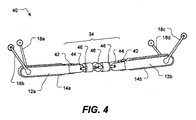
本発明の別の実施形態による1つの特定の例示のロボット式無限軌道が、図4に示される。ロボット式無限軌道車40は、第1のフレームユニット12aおよび第2のフレームユニット12bを備え、フレームユニットが上述のように無限軌道14a、14bを有する。関節アーム18a、18b、18c、18dが各フレームユニットに対向した対で配置される。第1のフレームユニットおよび第2のフレームユニットは作動リンク(actuated linkage)34によって連結されている。作動リンクは、少なくとも1つの軸を中心とした制御可能な曲げを提供する。たとえば、作動リンクはここに示されるように7つの異なる軸を中心とした曲げを提供する接合部を備えることができる。2つの接合部がヨー軸42を中心とした曲げを提供し、2つの接合部がピッチ軸44を中心とした曲げを提供し、2つの接合部がロール軸46を中心とした回転を提供し、1つの追加の曲げ接合部48が含まれる。この特定の接合部の配置は、ロボット式無限軌道車がとることができる姿勢においてかなりの可撓性を提供する。たとえば、2006年11月13日に出願され、参照によって本明細書に組み込まれる、本願の権利者が所有する「Serpentine Robotic Crawler」という名称の米国仮特許出願第60/858,917号は、接合部のこの特定の配置によって可能になるさまざまな姿勢および運動の動きを記載している。
One particular exemplary robotic endless track according to another embodiment of the invention is shown in FIG. The robot
図5に概略の形式で示されるように、ロボット式無限軌道車40は、それぞれ無限軌道14a、14bに連結された軌道駆動ユニット24a、24bを備える。アーム駆動ユニット26a、26bも備えられる。各アーム駆動ユニット26a、26bはそれぞれ、一対のアーム18a、18b、および18c、18dを制御するが、その代わりに各アームに対して個別の駆動ユニットを設けることもできる。駆動制御システム36が駆動ユニットに接続されて、ロボット式無限軌道車の推進を提供するために無限軌道およびアームの運動を調和する。作動リンク34は、ロボット式無限軌道車の運動および姿勢を調和させるために駆動制御システムにも接続できる。
As shown in schematic form in FIG. 5, the robotic
ロボット式無限軌道車に関して、さまざまな動作モードおよび姿勢が可能である。次に図4に示される構成を参照して、例を提供するが、本明細書に開示された他の構成も下記に説明される動作モードのうちのいくつかまたは全てが可能であることを理解されたい。 Various operation modes and postures are possible for a robotic endless track vehicle. An example will now be provided with reference to the configuration shown in FIG. 4, although other configurations disclosed herein are possible with some or all of the modes of operation described below. I want you to understand.
第1の姿勢が本明細書で「列」構成と呼ばれ、その場合に第1のフレーム12aおよび第2のフレーム12bが図6に示されるように一直線に配置される。フレームは、一直線上に整列することができるが、それは必須ではない。列構成は、小さな輪郭をもたらし、狭い通路および開口(たとえばトンネル60など)を通過できるようになる。ロボット式無限軌道車は、無限軌道14a、14bを同じ相対的な方向に移動するように駆動することによって、前方向および逆方向に移動できる。任意で、一方の無限軌道を駆動でき、他方の無限軌道が受動モードのままにされる。
The first orientation is referred to herein as a “column” configuration, in which case the
アーム18は、たとえば図6に示されるように、表面に接触し、ロボット式無限軌道車40に追加の長さを提供するために、フレームの端部を越えて延出するように配備することができる。追加された長さはまた、さらなる安定性をもたらす。これにより、ロボット式無限軌道車が間隙および穴(たとえばキャニヨン62などの)を渡る能力が向上する。
The
ロボット式無限軌道車40の回転は、さまざまな様式で行うことができる。1つのモードでは、作動リンク34は、第1のフレーム12aと第2のフレーム12bに角度を形成するために動作できる。別のモードでは、1つまたは複数のアーム18が延出して表面を掘削し、駆動が無限軌道14に加えられると、1つまたは複数のフレームが周囲にトルクを与える偏心の抵抗の点(または複数の点)を提供する。別のモードでは、作動リンクの1つまたは複数のアーム、および軌道の動作は、回転を行うために調整できる。
The rotation of the robotic
第2の姿勢が本明細書で「タンク」構成と呼ばれ、その場合に第1のフレーム12aおよび第2のフレーム12bが図7に示されるように横に並んで配置される。フレームは、平行であってもよいが、それは必須ではない。タンク構成は、たとえば険しい坂を移動する場合にロボット式無限軌道車40に側方の安定性をもたらす。ロボット式無限軌道車は、無限軌道14a、14bを同じ相対方向に駆動することによって前方向および逆方向に移動でき、無限軌道を反対方向に駆動することによって旋回される。一般に、タンク様構成でロボット式無限軌道車を移動させることは、無限軌道に(反対方向を含む)異なる駆動速度を加えることを伴う可能性がある。列構成に対して、無限軌道のうちの1つの方向の向きが逆になることに留意されたい。タンク構成では、アーム18は、さらなる安定性および/またはトラクションをもたらすために、延出して表面に接触することができる。
The second orientation is referred to herein as a “tank” configuration, in which case the
ロボット式無限軌道車は外側が上がる構成で、構造の外側が上がるように構成することもできる。図8に示されるように、ロボット式無限軌道車40は、無限軌道14の露出部分72、74が互いに向かい合い、構造の両側の外側表面76、78に接触するように、構造70の周りに巻きつけられる。アーム18は、さらなる安定性および/またはトラクションをもたらすために、フレーム12の端部を越えて延出し、構造の外側表面に接触することができる。たとえば、アームは、ロボット式無限軌道車を構造に中心を合わせて保持するのに役立つことができる。
The robot type endless track can be configured so that the outside is raised and the outside of the structure is raised. As shown in FIG. 8, the robotic
無限軌道は、構造を上下して移動させるようにロボット式無限軌道車を駆動できる。この外側が上がる構成で、たとえばポールを含む多くの異なる構造的なジオメトリを上げることができる。 Endless tracks can drive robotic endless tracks to move the structure up and down. The outer configuration above that, for example, it is possible to increase the number of different structural geometries including pole.
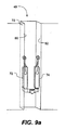
ロボット式無限軌道車は、構造の内側が上がるように構成することもできる。図9(a)および9(b)は、2つの異なる内側が上がる構成を示す。1つの内側が上がる構成では、ロボット式無限軌道車40は、無限軌道の露出部分72、74が互いに反対を向き、構造70の両側の内側表面80、82と接触するように構成される。アームは、構造の内側表面と接触するために、フレームの端部を越えて延出できる。アームは、図9(a)および9(b)に示されるように、その対応する無限軌道と同じ内側表面に接触するように配置できる。あるいは、アームは図10(a)の別の姿勢に示されるように、反対の内側表面に接触するように配置できる。図10(b)に示されるように別の代替として、無限軌道は1つの内側表面80と接触して同じ方向に面することができ、アームは反対の内側表面82に接触できる。さまざまな姿勢で、アームは無限軌道と内側表面の間の力を増加させるのに役立つことができ、無限軌道のトラクションを増加させる。内側が上がる構成は、パイプ、煙突、ウォールインテリアなどを上がるのに役立つことができる。
Robotic endless track vehicles can also be configured so that the inside of the structure is raised. 9 (a) and 9 (b) show a configuration in which two different inner sides are raised. In one upside configuration, the robotic
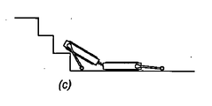
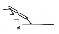
さまざまな関節運動が同様に、ロボット式無限軌道車に関して可能である。たとえば、図11(a)〜11(i)は、ロボット式無限軌道車40が1組の階段86を上っていることを示す、一連の図解の側面図を提供する。ロボット式無限軌道車は、図11(a)に示されるように、それがまだその姿勢になっていない場合に列構成になる。次いでロボット式無限軌道車は、前方アームが図11bに示されるように第1のフレームの前に延出する位置にアームを回転させる。次いで前方アームは、図11cに示されるように、最初の段を乗り越えるために、さらに回転され、第1のフレームの前部を持ち上げる。後方アームは、さらなる安定性および/またはトラクションをもたらすために、回転してロボット式無限軌道車の背後の表面に接触することができる。次いで軌道は、図11(d)に示されるように、第1の段の上でロボット式無限軌道車を前方に移動させるために、前方に駆動できる。次の段を上がるために、回転のシーケンスが前部のアームに関して繰り返される。後方アームは、図11(e)〜11(g)に示されるように、第2のフレームを持ち上げるのを助けるために使用することもできる。一般に、アームは、フレームユニットの上にある間はその遠位端が移動の方向に回転し、フレームユニットの下にある間は遠位端が移動の方向と反対に回転するように回転する。この動きは、アームが障害物を乗り越え、トラクションを増大させ、フレームユニットを障害物の上に持ち上げるのを助ける。したがって、アーム駆動ユニットがフレームユニットの重量を持ち上げるのに十分なトルクを有すると有効である。その代わりに、作動リンク34が、第2のフレームユニットによって支持されながら、第1のフレームユニットのフレームを持ち上げるのに十分なトルクを提供できる。1組の階段を上がるために使用されるのと同様の動きが、壁の穴に入るためにロボット式無限軌道車に関して使用できることが理解されよう。関節運動のさまざまなその他の組合せが、誘導される階段(またはその他の障害物)のディメンションに応じて有用であることを証明できる。本発明の実施形態で使用できるさらなる動作モードが、「Serpentine Robotic Crawler」という名称の上述の出願に説明される。
Various joint movements are possible as well for robotic endless cars. For example, FIGS. 11 (a) to 11 (i) provide a side view of a series of illustrations showing that the robotic
前述の議論は全体的に、関節アームの比較的単純な構成に注目したが、より複雑な配置が同様に使用できる。たとえば、関節アームは、複数の関節接合部を含むことができる。たとえば、作動リンクにおいて使用されるのと同様の接合部を関節アームで使用することもできる。工具、カメラなどのさまざまな付属器を関節アームに固定することもできる。たとえば、図12は、本発明の別の実施形態によるロボット式無限軌道車50を示す。ロボット式無限軌道車はそれぞれ軌道14a、14bを有するフレーム12a、12bを備える。接合部56aおよび56bによって共に連結された下方セグメント52a、52b、および上方セグメント54a、54bを有する接合されたアームがフレームに連結される。それぞれの接合されたアームは、カメラ60a、60bを備える。各アームの遠位端に、鋸歯状の刃先62a、62bが固定される。
The foregoing discussion generally focused on the relatively simple configuration of the articulated arm, but more complex arrangements can be used as well. For example, the articulated arm can include a plurality of articulation joints. For example, joints similar to those used in actuation links can be used in articulated arms. Various attachments such as tools and cameras can be fixed to the joint arm. For example, FIG. 12 shows a robotic endless track 50 according to another embodiment of the present invention. The robotic endless track vehicle includes
接合されたアームは、多くの目的に使用できる。1つの目的はカメラ60a、60bの支持である。下方セグメント52a、52bは、(たとえばよりよい視界をもたらすために高さを増加し、またはより低い輪郭をもたらすために高さを減少させるために)、カメラを上げまたは下げるように回転できる。上方セグメント54a、54bは、たとえば上記に論じたように、推進を補助するために回転できる。鋸歯状の刃先62a、62bは、たとえば上記に論じたように階段を上がる場合にトラクションをもたらすのに役立つことができる。
The joined arms can be used for many purposes. One purpose is to support the
カメラは、誘導を補助するために使用できる。たとえば、前方のカメラ60aは、主に環境を精査するために使用でき、後方のカメラ60bは制御の目的でロボット式無限軌道車の姿勢を観測するために使用できる。
The camera can be used to assist with guidance. For example, the
もちろん、たとえばライト、クランプ、グリッパ、マニピュレータ、カッタ、ドリル、材料採取器、センサなどを含むその他のさまざまな工具がアームの端部に固定できる。たとえば、レーダ、ライダ、温度センサ、化学センサ、力センサ、運動検出器、マイクロフォン、アンテナなどを含むさまざまなセンサが使用できる。 Of course, various other tools can be secured to the end of the arm including, for example, lights, clamps, grippers, manipulators, cutters, drills, material pickers, sensors, and the like. For example, various sensors can be used including radar, lidar, temperature sensor, chemical sensor, force sensor, motion detector, microphone, antenna and the like.
別の実施形態では、2つの自由度における運動をもたらすアームが使用できる。第1の自由度は、たとえば上述したようにフレームへの取付点に対して正接する平面においての回転運動であることができる。第2の自由度は、平面に垂直な側方の運動であることができる。たとえば、側方の運動をもたらすために、制御可能なコンプライアンスを有する構造または接合部を有するアームが使用できる。制御可能なコンプライアンスは、アームにバネ付勢を与えることによって得られ、その場合に、バネ定数がアクチュエータによって動作の間に変更できる。 In another embodiment, an arm that provides movement in two degrees of freedom can be used. The first degree of freedom can be, for example, rotational movement in a plane tangent to the attachment point to the frame as described above. The second degree of freedom can be a lateral movement perpendicular to the plane. For example, an arm having a controllable compliance structure or joint can be used to provide lateral movement. Controllable compliance is obtained by applying a spring bias to the arm, in which case the spring constant can be changed during operation by the actuator.
アームを側方に動かすことによって、さまざまな追加の動作モードが可能である。たとえば、アームは尖った配置を形成するために、内側に偏らされ、ロボット式無限軌道車の前に延出できる。この姿勢は、ロボット式無限軌道車が密度の高い植生などの障害物を通過するのを補助できる。 Various additional modes of operation are possible by moving the arm to the side. For example, the arms can be biased inward to extend in front of the robotic endless track to form a pointed arrangement. This posture can assist the robotic endless track passing through obstacles such as dense vegetation.
別の例として、アームは、たとえば外側が上がる構成で凸の外側表面の上を把持する場合に、トラクションを増加させるために、互いに向かって内側に偏らせることができる。アームは、たとえば内側が上がる構成で凹に湾曲した内側表面の上にトラクションをもたらす場合に、外側に偏らせることもできる。別の例として、アームはアウトリガを形成するために外側に偏らせることもでき、ロボット式無限軌道車にさらなる安定性をもたらす。 As another example, the arms can be biased inward toward each other to increase traction, for example when gripping over a convex outer surface in an up-out configuration. The arms can also be biased outward, for example when providing traction on a concavely curved inner surface in an upside-down configuration. As another example, the arms can be biased outward to form an outrigger, which provides additional stability to the robotic endless track.
ある程度まとめ、反復すると、本発明の実施形態によるロボット式無限軌道車は、さまざまな用途および環境において配備できる。たとえば、限定としてではないが、用途には捜索救難、軍事作戦、および生産工程を含むことができる。ロボット式無限軌道車は、不安定な建築物、軍事衝突状態、および化学的汚染、生物学的汚染、または核汚染された環境などの危険な環境に人間を曝す必要をなくすのに役立つことができる。ロボット式無限軌道車の構成上の柔軟性により、多数の動作モードが提供できる。たとえば、タンク様構成での運動は高い安定性をもたらすことができる。列様の構成での運動は、狭い経路またはパイプを通るアクセス、および間隙の橋渡しを可能にすることができる。構造(たとえばポール)の外側が上がること、および構造(たとえば煙突)の内側が上がることも可能である。階段を上がることも例示されている。 To some extent summarized and repeated, robotic endless track vehicles according to embodiments of the present invention can be deployed in a variety of applications and environments. For example, but not by way of limitation, applications can include search and rescue, military operations, and production processes. Robotic tracked vehicles can help eliminate the need to expose humans to unstable buildings, military collision situations, and hazardous environments such as chemical, biological, or nuclear contaminated environments. it can. The configuration flexibility of a robotic endless track vehicle can provide a number of operating modes. For example, movement in a tank-like configuration can provide high stability. Movement in a row-like configuration can allow access through narrow paths or pipes and bridging gaps. It is also possible for the outside of the structure (eg pole) to rise and the inside of the structure (eg chimney) to rise. It is also illustrated to go up the stairs.
前述の詳細な説明は、特定の例示の実施形態を参照して本発明を説明する。しかし、添付の特許請求の範囲に明記したように本発明の範囲から逸脱せずにさまざまな修正および変形を行うことが可能であることが理解されよう。詳細な説明および添付の図面は、限定するものではなく例示のものにすぎないとみなされ、全てのそのような修正または変更は、もしあれば、本明細書に説明および明記されるように本発明の範囲内に収まることが意図される。 The foregoing detailed description describes the invention with reference to specific exemplary embodiments. However, it will be understood that various modifications and changes may be made without departing from the scope of the present invention as set forth in the appended claims. The detailed description and accompanying drawings are to be regarded as illustrative rather than limiting, and all such modifications or changes, if any, may be considered as described and specified herein. It is intended to be within the scope of the invention.
より具体的には、本発明の例示の実施形態を本明細書に説明してきたが、本発明はこれらの実施形態に限定されず、前述の詳細な説明に基づいて当業者によって理解されるような修正、省略、組合せ(たとえばさまざまな実施形態の間の態様の)、改造、および/または改変を有する任意および全ての実施形態を含む。特許請求の範囲における限定は、特許請求の範囲で使用された言語に基づいて広く解釈され、前述の詳細な説明で、または出願手続中に説明された例に限定されず、その例は排他的でないと解釈される。たとえば、本開示において、用語「好ましくは」は非排他的であり、「好ましいが、それには限定されない」を意味することが意図される。任意の方法または製法のクレームに列挙された任意のステップは、任意の順で実行でき、特許請求の範囲に表された順に限定されない。したがって、本発明の範囲は、上記に与えられた説明および例によってではなく、添付の特許請求の範囲およびその法的な等価物によってのみ決定されるべきである。 More specifically, although exemplary embodiments of the present invention have been described herein, the present invention is not limited to these embodiments and will be understood by those skilled in the art based on the foregoing detailed description. Any and all embodiments having various modifications, omissions, combinations (eg of aspects between the various embodiments), modifications, and / or alterations are included. The limitations in the claims are to be construed broadly based on the language used in the claims, and are not limited to the examples described in the foregoing detailed description or during the filing process, the examples being exclusive Not interpreted. For example, in the present disclosure, the term “preferably” is non-exclusive and is intended to mean “preferably but not limited to”. Any steps recited in any method or process claims may be executed in any order and are not limited to the order presented in the claims. Accordingly, the scope of the invention should be determined solely by the appended claims and their legal equivalents, rather than by the description and examples given above.
Claims (21)
一連の構成で前記フレームユニットを連結する少なくとも1つの作動リンクであって、少なくとも1つの軸を中心とした制御可能な曲げをもたらすように構成された少なくとも1つの作動接合部を有する作動リンクと、
アーム付フレームユニットを形成するために前記複数のフレームユニットの少なくとも1つの両側に配置された少なくとも2つの独立可動アームであって、少なくとも1つのディメンションで可動であり、推進するための表面との係合および係合解除が可能であるアームとを備え、
前記可動アームは、地面または構造の外面に接触するために前記フレームユニットの端部を越えて延びることができる、
ロボット式無限軌道車。 A plurality of frame units, each frame unit having only one endless track rotatably coupled thereto, wherein at least one surface of the endless track is a surface for propelling the frame unit A plurality of frame units exposed to allow engagement with the
At least one actuating link connecting the frame units in a series of configurations, the actuating link having at least one actuating joint configured to provide a controllable bend about at least one axis;
At least two independently movable arms disposed on both sides of at least one of the plurality of frame units to form a frame unit with arms, wherein the arms are movable in at least one dimension and are associated with a surface for propulsion; An arm that can be engaged and disengaged,
The movable arm can extend beyond the end of the frame unit to contact the ground or the outer surface of the structure;
Robotic endless track car.
前記無限軌道に連結された第1の駆動ユニットと、
前記少なくとも2つのアームに連結された第2の駆動ユニットと、
前記第1および第2の駆動ユニットに接続され、前記ロボット式無限軌道車の推進を提供するために前記無限軌道および前記少なくとも2つのアームの運動を調整するように構成された駆動制御システムとを備える、請求項1に記載のロボット式無限軌道車。 The frame unit with arm is
A first drive unit coupled to the endless track;
A second drive unit coupled to the at least two arms;
A drive control system connected to the first and second drive units and configured to coordinate movement of the endless track and the at least two arms to provide propulsion of the robotic endless track vehicle; The robotic endless track vehicle according to claim 1, comprising:
前記フレームユニットの両側に配置された少なくとも2つの関節アームであって、少なくとも1つのディメンションで互いに独立に可動であり、推進するための表面との係合および係合解除が可能である関節アームとを備え、
前記関節アームは、地面または構造の外面に接触するために前記フレームユニットの端部を越えて延びることができる、ロボット式無限軌道車。 A frame unit having only one endless track rotatably connected to the frame unit, at least one surface of the endless track being able to engage with a surface for propelling the frame unit A frame unit that is exposed to
At least two articulated arms arranged on opposite sides of the frame unit, movable independently of each other in at least one dimension, and capable of engaging and disengaging with a surface for propulsion; With
The robotic endless track vehicle, wherein the articulated arm can extend beyond the end of the frame unit to contact the ground or the outer surface of the structure.
(a)第1のフレームおよび第2のフレームを提供するステップであって、各フレームが、前記表面と係合するための露出した領域を備える1つだけの無限軌道を有し、前記1つの無限軌道が、前記無限軌道の回転をもたらすために駆動源に連結されるステップと、
(b)前記第1のフレームおよび第2のフレームの少なくとも1つの両側に配置された少なくとも2つの関節アームを提供するステップであって、1つのアームが前記第1のフレームと前記第2のフレームのそれぞれに取り付けられ、前記アームが少なくとも1つのディメンションで互いに対して、およびその対応するフレームに対して独立に可動であり、且つ推進するための表面との係合および係合解除が可能であり、前記関節アームは、地面または構造の外面に接触するために前記フレームの端部を越えて延びることができる、ステップと、
(c)前記第1のフレームと前記第2のフレームの間に連結された多自由度の作動リンクアームを提供するステップと、
(d)前記表面の上で前記ロボット式無限軌道車の姿勢および運動を制御するために、前記無限軌道の回転、前記関節アームの運動、および前記多自由度のリンクアームの作動を調整させるステップとを含む方法。 A method of operating a robotic endless track vehicle on the surface,
Comprising the steps of: (a) providing a first and second frames, each frame having a track of only one having an exposed area for engagement with said surface, said one An endless track is coupled to a drive source to effect rotation of the endless track;
(B) providing at least two articulated arms disposed on both sides of at least one of the first frame and the second frame, wherein one arm is the first frame and the second frame; The arms are independently movable with respect to each other and with respect to their corresponding frames in at least one dimension and are capable of engaging and disengaging with surfaces for propulsion The articulated arm can extend beyond the end of the frame to contact the ground or the outer surface of the structure;
(C) providing a multi-degree-of-freedom actuating link arm connected between the first frame and the second frame;
(D) adjusting the rotation of the endless track, the motion of the articulated arm, and the operation of the multi-degree of freedom link arm to control the attitude and motion of the robotic endless track on the surface; And a method comprising.
前記第1のフレームおよび前記第2のフレームのうちの1つの前記端部を越えて前方に延出するように、前記関節アームを配置するステップと、
尖った構成を形成するために、前記関節アームを内側に偏らせるステップとを含む、請求項12に記載の方法。 Step (d) is
Positioning the articulated arm to extend forward beyond the end of one of the first frame and the second frame;
13. The method of claim 12, comprising biasing the articulated arm inward to form a pointed configuration.
Applications Claiming Priority (3)
| Application Number | Priority Date | Filing Date | Title |
|---|---|---|---|
| US85891506P | 2006-11-13 | 2006-11-13 | |
| US60/858,915 | 2006-11-13 | ||
| PCT/US2007/023870 WO2008076193A2 (en) | 2006-11-13 | 2007-11-13 | Tracked robotic crawler having a moveable arm |
Publications (3)
| Publication Number | Publication Date |
|---|---|
| JP2010509128A JP2010509128A (en) | 2010-03-25 |
| JP2010509128A5 JP2010509128A5 (en) | 2011-01-27 |
| JP5411702B2 true JP5411702B2 (en) | 2014-02-12 |
Family
ID=39494668
Family Applications (1)
| Application Number | Title | Priority Date | Filing Date |
|---|---|---|---|
| JP2009536343A Active JP5411702B2 (en) | 2006-11-13 | 2007-11-13 | Robotic endless track car with movable arm |
Country Status (7)
| Country | Link |
|---|---|
| US (1) | US8185241B2 (en) |
| EP (2) | EP2099672B1 (en) |
| JP (1) | JP5411702B2 (en) |
| CN (1) | CN101583530B (en) |
| AT (1) | ATE522431T1 (en) |
| IL (1) | IL198711A (en) |
| WO (1) | WO2008076193A2 (en) |
Families Citing this family (73)
| Publication number | Priority date | Publication date | Assignee | Title |
|---|---|---|---|---|
| US20080136254A1 (en) | 2006-11-13 | 2008-06-12 | Jacobsen Stephen C | Versatile endless track for lightweight mobile robots |
| DE602007013793D1 (en) | 2006-11-13 | 2011-05-19 | Raytheon Co | ADJUSTABLE TRACK ARRANGEMENT FOR A RAILROAD ROBOT |
| JP2010526590A (en) | 2007-05-07 | 2010-08-05 | レイセオン・サルコス・エルエルシー | Method for manufacturing a composite structure |
| US8571711B2 (en) | 2007-07-10 | 2013-10-29 | Raytheon Company | Modular robotic crawler |
| US10427290B2 (en) | 2017-07-18 | 2019-10-01 | General Electric Company | Crawler robot for in situ gap inspection |
| FR2929228B1 (en) * | 2008-03-28 | 2010-06-18 | Thales Sa | POKER ROBOT ROBOT. |
| US7954575B1 (en) * | 2008-09-10 | 2011-06-07 | Bloxsom Joel O | Leader string pull-through machine |
| US8525124B2 (en) | 2008-11-03 | 2013-09-03 | Redzone Robotics, Inc. | Device for pipe inspection and method of using same |
| US8392036B2 (en) | 2009-01-08 | 2013-03-05 | Raytheon Company | Point and go navigation system and method |
| WO2010144813A1 (en) * | 2009-06-11 | 2010-12-16 | Raytheon Sarcos, Llc | Method and system for deploying a surveillance network |
| KR101208919B1 (en) * | 2010-03-25 | 2012-12-06 | 주식회사 유진로봇 | Drivig Arm having Rake Wheel and Mobile Robot therewith |
| WO2012044663A1 (en) * | 2010-09-30 | 2012-04-05 | Schlee Keith L | Multi-unit mobile robot |
| US9522595B2 (en) | 2011-01-27 | 2016-12-20 | Irobot Defense Holdings, Inc. | Small unmanned ground vehicle |
| US9346499B2 (en) * | 2011-01-27 | 2016-05-24 | Irobot Corporation | Resilient wheel assemblies |
| AU2012214062B2 (en) * | 2011-02-11 | 2016-12-08 | University Of Regina | Adaptable vehicle |
| US20120205168A1 (en) * | 2011-02-11 | 2012-08-16 | Christopher Ryan Flynn | Robot reconfigurable for insertion through a narrow opening |
| CN102267503B (en) * | 2011-05-06 | 2012-07-25 | 北京航空航天大学 | Small combined robot formed by monomer throwing robots |
| JP5542092B2 (en) * | 2011-05-12 | 2014-07-09 | 学校法人千葉工業大学 | Unmanned traveling vehicle |
| US9004200B2 (en) * | 2011-09-09 | 2015-04-14 | Pinhas Ben-Tzvi | Mobile robot with hybrid traction and mobility mechanism |
| US8574021B2 (en) | 2011-09-23 | 2013-11-05 | Mattel, Inc. | Foldable toy vehicles |
| JP2013113597A (en) * | 2011-11-25 | 2013-06-10 | Hitachi-Ge Nuclear Energy Ltd | Inspection vehicle, apparatus for inspecting inside of container, and image processing method |
| US9248875B2 (en) | 2012-04-17 | 2016-02-02 | Robo-team Ltd. | Driving flipper with robotic arm |
| US8393422B1 (en) | 2012-05-25 | 2013-03-12 | Raytheon Company | Serpentine robotic crawler |
| US20140031977A1 (en) * | 2012-07-27 | 2014-01-30 | Engineering Services Inc. | Modular mobile robot |
| DE102012109040B4 (en) * | 2012-09-25 | 2014-12-11 | BIBA - Bremer Institut für Produktion und Logistik GmbH | Climbing apparatus and method for performing activities on stacked objects |
| CN102887187A (en) * | 2012-10-23 | 2013-01-23 | 四川省电力公司西昌电业局 | Electromagnetic-type intelligent climbing robot |
| US9031698B2 (en) | 2012-10-31 | 2015-05-12 | Sarcos Lc | Serpentine robotic crawler |
| US9409292B2 (en) * | 2013-09-13 | 2016-08-09 | Sarcos Lc | Serpentine robotic crawler for performing dexterous operations |
| US9566711B2 (en) | 2014-03-04 | 2017-02-14 | Sarcos Lc | Coordinated robotic control |
| CN104002880B (en) * | 2014-06-03 | 2016-03-23 | 东南大学 | The autonomous stair activity control method of a kind of caterpillar mobile robot with guide arm |
| JP2014238403A (en) * | 2014-07-07 | 2014-12-18 | 日立Geニュークリア・エナジー株式会社 | Survey vehicle, survey device in container, and image processing method |
| US9096281B1 (en) * | 2014-07-30 | 2015-08-04 | Engineering Services Inc. | Dual mode mobile robot |
| US9561829B1 (en) * | 2014-09-03 | 2017-02-07 | X Development Llc | Robotic leg with multiple robotic feet |
| CN104647341B (en) * | 2015-02-28 | 2016-04-06 | 东北大学 | A kind of obstacle crossing type cableless remote control is got rid of the danger Detecting Robot |
| RU2603816C1 (en) * | 2015-06-24 | 2016-11-27 | Федеральное государственное бюджетное образовательное учреждение высшего профессионального образования "Государственный университет - учебно-научно-производственный комплекс" (ФГБОУ ВПО "Госуниверситет-УНПК") | Vehicle |
| US10071303B2 (en) | 2015-08-26 | 2018-09-11 | Malibu Innovations, LLC | Mobilized cooler device with fork hanger assembly |
| US9637186B1 (en) | 2015-12-03 | 2017-05-02 | Engineering Services Inc. | Dual mode vehicle |
| GB2548917B (en) * | 2016-04-01 | 2020-08-05 | Provost Fellows Found Scholars & Other Members Board College Holy & Und | Obstacle crossing robot |
| US10807659B2 (en) | 2016-05-27 | 2020-10-20 | Joseph L. Pikulski | Motorized platforms |
| JP6715462B2 (en) * | 2016-06-02 | 2020-07-01 | パナソニックIpマネジメント株式会社 | Mobile robot |
| US10131057B2 (en) | 2016-09-20 | 2018-11-20 | Saudi Arabian Oil Company | Attachment mechanisms for stabilzation of subsea vehicles |
| US11608697B2 (en) * | 2016-11-21 | 2023-03-21 | Sam SCHROIT | System for the operational and performance efficiency improvement of wireline tractors |
| CN108340364B (en) * | 2017-01-24 | 2020-09-15 | 南京原觉信息科技有限公司 | Crawling machine device and deployment method thereof |
| WO2018154424A1 (en) | 2017-02-21 | 2018-08-30 | Induna Robotics (Pty) Ltd | Robotic limb arrangement and associated robot |
| US10603802B2 (en) | 2017-07-18 | 2020-03-31 | General Electric Company | End region inspection module and method for in situ gap inspection robot system |
| US10427734B2 (en) * | 2017-07-18 | 2019-10-01 | General Electric Company | Omnidirectional traction module for a robot |
| US10596713B2 (en) | 2017-07-18 | 2020-03-24 | General Electric Company | Actuated sensor module and method for in situ gap inspection robots |
| US10434641B2 (en) | 2017-07-18 | 2019-10-08 | General Electric Company | In situ gap inspection robot system and method |
| CN107521576B (en) * | 2017-08-24 | 2023-09-05 | 广州南洋理工职业学院 | Robot capable of walking on ground and climbing stairs |
| CA3081665C (en) | 2017-09-19 | 2021-01-05 | Arix Technologies, Inc. | Pipe traversing apparatus and methods |
| CN107972755A (en) * | 2017-12-27 | 2018-05-01 | 同方威视技术股份有限公司 | Container climbing robot |
| CN108188467B (en) * | 2018-03-19 | 2024-04-09 | 江苏科技大学 | Self-propelled device for cutting corrugated pipe |
| US11247737B2 (en) * | 2018-04-23 | 2022-02-15 | Eagle Technology, Llc | UGV with adaptive stabilizer |
| US20200101804A1 (en) * | 2018-09-28 | 2020-04-02 | Beijing Jingdong Shangke Information Technology Co., Ltd. | Connector for connecting trailers in mobile robotic device and method of controlling the same |
| CN109533051B (en) * | 2018-11-29 | 2020-09-18 | 北京理工大学 | Convertible stair climbing robot with collapsible swing arm |
| US11097796B2 (en) * | 2018-11-29 | 2021-08-24 | Saudi Arabian Oil Company | Articulated magnet-bearing legs for UAV landing on curved surfaces |
| CN109557173B (en) * | 2019-01-17 | 2023-12-22 | 中国石油大学(北京) | Nondestructive testing device |
| CN109911046B (en) * | 2019-03-12 | 2023-12-15 | 无锡金诚工程技术服务有限公司 | Suspension crawler type climbing robot |
| CN109849018A (en) * | 2019-04-04 | 2019-06-07 | 华夏天信(北京)智能低碳技术研究院有限公司 | A kind of mine disaster relief snake-shaped robot |
| CN110181534A (en) * | 2019-06-24 | 2019-08-30 | 国网安徽省电力有限公司 | A kind of climbing robot |
| CN110328651A (en) * | 2019-07-29 | 2019-10-15 | 东北大学 | Towards old man can obstacle detouring accompany and attend to robot |
| US11833674B2 (en) * | 2019-08-14 | 2023-12-05 | Honeybee Robotics, Llc | Bi-directional robotic crawler for transporting a sensor system about a structure |
| US11154989B2 (en) | 2019-09-27 | 2021-10-26 | Arix Technologies, Inc. | Pipe traversing apparatus, sensing, and controls |
| CN110789626B (en) * | 2019-10-21 | 2021-09-14 | 陈迎高 | Foldable magnetic adsorption wall climbing detection device and detection method thereof |
| CN111267953B (en) * | 2020-02-06 | 2021-03-16 | 北京中安吉泰科技有限公司 | Steering device of flexible wall-climbing robot |
| US10797473B1 (en) * | 2020-03-20 | 2020-10-06 | Smart Prototype, Inc. | Cable rod guiding device |
| US20220204100A1 (en) | 2020-12-31 | 2022-06-30 | Sarcos Corp. | Coupleable, Unmanned Ground Vehicles with Coordinated Control |
| US11754514B2 (en) | 2021-08-13 | 2023-09-12 | Arix Technologies, Inc. | Radiography inspection and fail-safe mechanism for pipe traversing robots |
| CN114295336B (en) * | 2021-11-12 | 2023-06-06 | 国网宁夏电力有限公司吴忠供电公司 | Non-destructive detection method for annular automatic attaching suspension arm through crawler travel |
| CN114794991B (en) * | 2022-06-02 | 2024-01-16 | 南通大学 | Control method for stair cleaning robot to go downstairs without turning around |
| CN115303380B (en) * | 2022-10-12 | 2022-12-27 | 齐鲁工业大学 | Bionic wall-climbing inspection robot |
| CN116159318A (en) * | 2022-12-09 | 2023-05-26 | 哈尔滨理工大学 | Martial art arena robot using triangular crawler chassis |
| CN117022472B (en) * | 2023-10-08 | 2023-12-12 | 四川职业技术学院 | Fire rescue robot capable of quickly crossing steps and control method |
Family Cites Families (307)
| Publication number | Priority date | Publication date | Assignee | Title |
|---|---|---|---|---|
| US858917A (en) | 1907-03-19 | 1907-07-02 | Samuel Edgar Snedeker | Window-screen. |
| US1107874A (en) | 1911-11-06 | 1914-08-18 | Bullock Tractor Company | Vehicle. |
| US1112460A (en) | 1913-04-21 | 1914-10-06 | Harry W Leavitt | Tractor. |
| US1515756A (en) | 1922-05-12 | 1924-11-18 | Roy Irene | Articulated coupling device for heavy loads |
| GB392392A (en) | 1931-09-15 | 1933-05-18 | Leon Martinage | Improvements in and relating to endless track vehicles |
| US2025999A (en) | 1932-01-25 | 1935-12-31 | Edward C Myers | Rubber covered flexible track |
| US2082920A (en) | 1935-12-24 | 1937-06-08 | Aulmont W Tye | Trailer |
| US2129557A (en) | 1937-06-09 | 1938-09-06 | Charles H Beach | Detachable traction lug |
| US2312072A (en) | 1940-03-07 | 1943-02-23 | Tenger Victoria | Endless track for vehicles |
| US2345763A (en) | 1941-02-27 | 1944-04-04 | Goodrich Co B F | Flexible track for self-laying track vehicles |
| US2311475A (en) | 1941-09-19 | 1943-02-16 | Theodore G Schmeiser | Auxiliary traction wheel |
| US2329582A (en) | 1942-11-02 | 1943-09-14 | Harold M Bishop | Tread |
| US5570992A (en) | 1954-07-28 | 1996-11-05 | Lemelson; Jerome H. | Free-traveling manipulator with optical feedback control and methods |
| US2701169A (en) | 1954-08-18 | 1955-02-01 | Edgar M Cannon | Mud lug for endless traction track links |
| US2850147A (en) | 1954-08-20 | 1958-09-02 | James M Hill | Mobile curvable conveyor |
| US2933143A (en) | 1957-06-25 | 1960-04-19 | Canadair Ltd | Articulated vehicle |
| US3060972A (en) | 1957-08-22 | 1962-10-30 | Bausch & Lomb | Flexible tube structures |
| US3037571A (en) | 1959-08-17 | 1962-06-05 | Schield Bantam Company | Wide base crawler |
| US2967737A (en) | 1959-11-30 | 1961-01-10 | George V Moore | Detachable traction units |
| US3166138A (en) | 1961-10-26 | 1965-01-19 | Jr Edward D Dunn | Stair climbing conveyance |
| US3190286A (en) | 1961-10-31 | 1965-06-22 | Bausch & Lomb | Flexible viewing probe for endoscopic use |
| US3223462A (en) | 1963-04-25 | 1965-12-14 | Boeing Co | Endless track for a track laying vehicle |
| US3266059A (en) | 1963-06-19 | 1966-08-16 | North American Aviation Inc | Prestressed flexible joint for mechanical arms and the like |
| US3215219A (en) | 1963-07-22 | 1965-11-02 | Lockheed Aircraft Corp | Articulated vehicle |
| DE1505007B2 (en) | 1965-02-11 | 1976-07-22 | Eisen- Und Drahtwerk Erlau Ag, 7080 Aalen | SLIDING PROTECTION OR PROTECTIVE TIRE CHAIN FOR TIRE OF A MOTOR VEHICLE'S WHEELS |
| US3284964A (en) | 1964-03-26 | 1966-11-15 | Saito Norio | Flexible beam structures |
| US3311424A (en) | 1965-06-03 | 1967-03-28 | Marval & O Farrell | Tractive device comprising a belt driven soft roller |
| US3362492A (en) | 1966-02-14 | 1968-01-09 | Darrell L. Hansen | Snowbike attachment |
| GB1199729A (en) | 1966-10-24 | 1970-07-22 | Rowland Lewis Robert Morgan | Tractor Vehicle for Underwater Use |
| US3565198A (en) | 1967-06-26 | 1971-02-23 | Whiting Corp | Steering, driving and single track support systems for vehicles |
| US3497083A (en) | 1968-05-10 | 1970-02-24 | Us Navy | Tensor arm manipulator |
| US3489236A (en) | 1968-08-01 | 1970-01-13 | Us Army | Egressing device for military vehicles |
| US3572325A (en) | 1968-10-25 | 1971-03-23 | Us Health Education & Welfare | Flexible endoscope having fluid conduits and control |
| US3609804A (en) | 1969-08-27 | 1971-10-05 | Marvin Glass & Associates | Vehicle |
| US3808078A (en) | 1970-01-05 | 1974-04-30 | Norfin | Glass fiber cable, method of making, and its use in the manufacture of track vehicles |
| US3715146A (en) | 1970-01-19 | 1973-02-06 | W Robertson | Snow cleat and track for tracked vehicle |
| US3650343A (en) | 1970-03-12 | 1972-03-21 | John B Helsell | Ski slope traversing and conditioning vehicle |
| US3700115A (en) | 1970-09-17 | 1972-10-24 | Koehring Co | Vehicle with variable width ground supports |
| US3707218A (en) | 1970-10-26 | 1972-12-26 | Mackey M Payne | Conveyor apparatus |
| US3757635A (en) | 1971-03-23 | 1973-09-11 | F Hickerson | Multi-purpose munitions carrier |
| US3974907A (en) | 1971-10-29 | 1976-08-17 | Gordon A. Brewer | Flexible mobile conveyor |
| US3712481A (en) | 1971-12-23 | 1973-01-23 | Mc Donnell Douglas Corp | Actuator |
| US3841424A (en) | 1971-12-27 | 1974-10-15 | Caterpillar Tractor Co | Triangular track resilient bogie suspension |
| US3820616A (en) | 1972-02-03 | 1974-06-28 | American Hoist & Derrick Co | Crawler vehicle with dual extensible side frames |
| US3933214A (en) | 1972-07-12 | 1976-01-20 | Guibord Georges E | All terrain pleasure vehicle |
| US3864983A (en) | 1972-09-15 | 1975-02-11 | Stephen C Jacobsen | Rotary-to-linear and linear-to-rotary motion converters |
| US3934664A (en) | 1973-02-01 | 1976-01-27 | Pohjola Jorma | Steering mechanism for track vehicles |
| US5672044A (en) | 1974-01-24 | 1997-09-30 | Lemelson; Jerome H. | Free-traveling manipulator with powered tools |
| FI51306C (en) | 1975-01-30 | 1976-12-10 | Pohjola Jorma | Method and apparatus in a swivel vehicle. |
| US4068905A (en) | 1975-09-10 | 1978-01-17 | Black Chester A | Detachable road protecting device for tracked vehicles |
| US4059315A (en) | 1976-01-02 | 1977-11-22 | Jolliffe James D | Cleat anchor for flexible vehicle track |
| NO137351C (en) | 1976-01-30 | 1978-02-22 | Trallfa Nils Underhaug As | FLEXIBLE ROBOT ARM. |
| BE845263A (en) | 1976-08-18 | 1976-12-16 | SELF-MOVING TOWER END | |
| US4109971A (en) | 1976-10-12 | 1978-08-29 | Black Chester A | Detachable road protecting devices for tracked vehicles |
| US4589460A (en) | 1978-01-03 | 1986-05-20 | Albee William H | Off road vehicles |
| US4218101A (en) | 1978-04-03 | 1980-08-19 | De Lorean Manufacturing Company | Low disturbance track cleat and ice calk structure for firm or icy snow |
| US4332424A (en) | 1978-04-03 | 1982-06-01 | De Lorean Manufacturing Company | Low disturbance track cleat and ice calk structure for firm or icy snow |
| SE419421B (en) | 1979-03-16 | 1981-08-03 | Ove Larson | RESIDENTIAL ARM IN SPECIAL ROBOT ARM |
| US4494417A (en) | 1979-03-16 | 1985-01-22 | Robotgruppen Hb | Flexible arm, particularly a robot arm |
| DE2926798C2 (en) | 1979-07-03 | 1986-05-28 | Klöckner-Werke AG, 4100 Duisburg | Chain scraper conveyor |
| US4339031A (en) | 1979-10-01 | 1982-07-13 | Joy Manufacturing Company | Monorail suspended conveyor system |
| US4260053A (en) | 1979-10-09 | 1981-04-07 | Hirosuke Onodera | Flexible conveyor belt |
| CA1118021A (en) | 1980-01-29 | 1982-02-09 | Her Majesty The Queen In Right Of Canada As Represented By The Minister Of National Defence Of Her Majesty's Canadian Government | Track for rope vehicle |
| DE3025840C2 (en) | 1980-07-08 | 1983-08-04 | Mowag Motorwagenfabrik Ag, Kreuzlingen | Chain link for a crawler belt |
| US4453611A (en) | 1980-10-10 | 1984-06-12 | Stacy Jr Jack C | Terrain vehicle having a single, latterally bendable track |
| US4636137A (en) | 1980-10-24 | 1987-01-13 | Lemelson Jerome H | Tool and material manipulation apparatus and method |
| US4713896A (en) | 1981-04-10 | 1987-12-22 | Jennens Eric G | Inshore submersible amphibious machines |
| JPS5880387U (en) * | 1981-11-27 | 1983-05-31 | 株式会社明電舎 | Traveling trolley equipped with a manipulator |
| US4489826A (en) | 1982-02-05 | 1984-12-25 | Philip Dubson | Adjustable apparatus |
| US4483407A (en) * | 1982-03-26 | 1984-11-20 | Hitachi, Ltd. | Variable configuration track laying vehicle |
| SE436175B (en) | 1982-07-05 | 1984-11-19 | Robotgruppen Hb | DEVICE FOR THE CONNECTION OF A ROBOT ARM OR SIMILAR INCLUDING ELEMENT |
| DE3236947A1 (en) | 1982-10-06 | 1984-04-12 | Rainer 6074 Rödermark Hitzel | PIPE MANIPULATOR FOR PIPING THROUGH PIPES |
| US4806066A (en) | 1982-11-01 | 1989-02-21 | Microbot, Inc. | Robotic arm |
| US4671774A (en) | 1983-01-28 | 1987-06-09 | Owsen Paul J | All terrain vehicle |
| GB8303694D0 (en) | 1983-02-10 | 1983-03-16 | Atomic Energy Authority Uk | Manipulators |
| US4900218A (en) | 1983-04-07 | 1990-02-13 | Sutherland Ivan E | Robot arm structure |
| US4551061A (en) | 1983-04-18 | 1985-11-05 | Olenick Ralph W | Flexible, extensible robot arm |
| GB2145691B (en) | 1983-08-29 | 1987-06-03 | Toshiba Kk | Extendible and contractable arms |
| US4661039A (en) | 1983-10-20 | 1987-04-28 | Donaldson Company | Flexible-frame robot |
| CA1245510A (en) | 1984-03-05 | 1988-11-29 | Arktos Developments Ltd. | All terrain vehicle and method of operating same |
| JPS6120484U (en) * | 1984-07-12 | 1986-02-06 | カシオ計算機株式会社 | running car |
| JPS6154378A (en) * | 1984-08-24 | 1986-03-18 | Chubu Electric Power Co Inc | Automatic ascending and descending apparatus for stairs for robot |
| US4646906A (en) | 1984-09-06 | 1987-03-03 | Fairchild Incorporated | Apparatus for continuously conveying coal from a continuous miner to a remote floor conveyor |
| JPS6175069A (en) * | 1984-09-10 | 1986-04-17 | Mitsubishi Electric Corp | Moving unit |
| US4736826A (en) | 1985-04-22 | 1988-04-12 | Remote Technology Corporation | Remotely controlled and/or powered mobile robot with cable management arrangement |
| JPH0228152Y2 (en) * | 1985-05-01 | 1990-07-27 | ||
| FI852478L (en) | 1985-06-20 | 1986-12-21 | Reta-Myynti Ky | FOERFARANDE I FORDON MED SVAENGBAR LARVMATTA FOER ATT AOSTADKOMMA BAETTRE KOERSTABILITETER. |
| JPH0228153Y2 (en) * | 1985-08-20 | 1990-07-27 | ||
| US4752105A (en) | 1985-10-24 | 1988-06-21 | Barnard Jan H | Vehicle traction |
| FR2589238B1 (en) | 1985-10-25 | 1987-11-20 | Commissariat Energie Atomique | SENSOR FOR EFFORT AND TORQUE MEASUREMENT AND APPLICATIONS OF SUCH A SENSOR TO A PROBE AND TO A GRIPPING DEVICE |
| GB8526602D0 (en) | 1985-10-29 | 1986-11-05 | Secr Defence | Unmanned vehicle |
| US4700693A (en) | 1985-12-09 | 1987-10-20 | Welch Allyn, Inc. | Endoscope steering section |
| US4784042A (en) | 1986-02-12 | 1988-11-15 | Nathaniel A. Hardin | Method and system employing strings of opposed gaseous-fluid inflatable tension actuators in jointed arms, legs, beams and columns for controlling their movements |
| US4756662A (en) | 1986-03-31 | 1988-07-12 | Agency Of Industrial Science & Technology | Varible compliance manipulator |
| US4714125A (en) | 1986-05-05 | 1987-12-22 | Stacy Jr Jack C | Single laterally bendable track snowmobile |
| US4862047A (en) | 1986-05-21 | 1989-08-29 | Kabushiki Kaisha Komatsu Seisakusho | Apparatus for guiding movement of an unmanned moving body |
| US4765795A (en) | 1986-06-10 | 1988-08-23 | Lord Corporation | Object manipulator |
| DE3626238A1 (en) | 1986-08-02 | 1988-02-18 | Kloeckner Becorit Gmbh | Steerable tracklaying unit |
| JPS6332084U (en) * | 1986-08-19 | 1988-03-01 | ||
| US5219264A (en) | 1986-09-19 | 1993-06-15 | Texas Instruments Incorporated | Mobile robot on-board vision system |
| US4828339A (en) | 1986-09-30 | 1989-05-09 | Joy Technologies Inc. | Crawler chain |
| FR2609335B1 (en) | 1987-01-05 | 1989-04-14 | Protee | SYSTEM FOR TRACKING THE MOTION OF A TRACKED VEHICLE |
| JPS63237892A (en) | 1987-03-23 | 1988-10-04 | 株式会社小松製作所 | Flexible arm |
| GB8709125D0 (en) | 1987-04-15 | 1987-05-20 | Siren A O | All-terrain hydrofoil train |
| US4828453A (en) | 1987-04-21 | 1989-05-09 | The United States Of America As Represented By The United States Department Of Energy | Modular multimorphic kinematic arm structure and pitch and yaw joint for same |
| US4796607A (en) | 1987-07-28 | 1989-01-10 | Welch Allyn, Inc. | Endoscope steering section |
| JPS6471686A (en) | 1987-09-09 | 1989-03-16 | Komatsu Mfg Co Ltd | Flexible arm robot |
| US4848179A (en) | 1988-02-16 | 1989-07-18 | Trw Inc. | Flexidigit robotic manipulator |
| US5021798A (en) | 1988-02-16 | 1991-06-04 | Trw Inc. | Antenna with positionable reflector |
| US5046914A (en) | 1988-07-12 | 1991-09-10 | Cybermation, Inc. | Parallel lifting device |
| US4862808A (en) | 1988-08-29 | 1989-09-05 | Gas Research Institute | Robotic pipe crawling device |
| US4932831A (en) | 1988-09-26 | 1990-06-12 | Remotec, Inc. | All terrain mobile robot |
| FR2638813B1 (en) | 1988-11-09 | 1991-02-01 | Nancy Ecole Sup Sciences Techn | SELF-PROPELLED VEHICLE FOR GRINDING OF PIPING |
| DE4000348A1 (en) | 1989-03-06 | 1990-09-13 | Hewlett Packard Co | DEVICE AND METHOD FOR MONITORING THE MOVEMENTS OF A FLEXIBLE ROBOT |
| US4932491A (en) | 1989-03-21 | 1990-06-12 | The United States Of America As Represented By The Administrator Of The National Aeronautics And Space Administration | Body steered rover |
| FR2651201B1 (en) | 1989-08-31 | 1991-10-25 | Framatome Sa | VEHICLE WITH INCLINABLE TRACKS. |
| US5018591A (en) | 1990-04-24 | 1991-05-28 | Caterpillar Inc. | Track laying work vehicle |
| US5080000A (en) | 1990-05-11 | 1992-01-14 | Bubic Frank R | Flexible robotic links and manipulator trunks made thereform |
| US5205612A (en) | 1990-05-17 | 1993-04-27 | Z C Mines Pty. Ltd. | Transport apparatus and method of forming same |
| EP0465743A1 (en) | 1990-07-12 | 1992-01-15 | British Aerospace Public Limited Company | Teach and report probe for a robot arm |
| US5588688A (en) | 1990-08-06 | 1996-12-31 | Sarcos, Inc. | Robotic grasping apparatus |
| US4997790A (en) * | 1990-08-13 | 1991-03-05 | Motorola, Inc. | Process for forming a self-aligned contact structure |
| US5186526A (en) | 1990-08-31 | 1993-02-16 | General Chemical Corporation | One-piece crawler pad |
| US5252870A (en) | 1991-03-01 | 1993-10-12 | Jacobsen Stephen C | Magnetic eccentric motion motor |
| US5142932A (en) | 1991-09-04 | 1992-09-01 | The United States Of America As Represented By The Administrator Of The National Aeronautics And Space Administration | Flexible robotic arm |
| DE4133605C2 (en) | 1991-10-10 | 1994-05-11 | Siemens Ag | Flexible robot arm |
| US5317952A (en) | 1991-11-22 | 1994-06-07 | Kinetic Sciences Inc. | Tentacle-like manipulators with adjustable tension lines |
| US5428713A (en) | 1991-11-25 | 1995-06-27 | Kabushiki Kaisha Toshiba | Compound module type manipulator apparatus |
| US5562843A (en) | 1991-12-28 | 1996-10-08 | Joven Electric Co., Ltd. | Industrial robot with contact sensor |
| US5199771A (en) | 1992-03-02 | 1993-04-06 | Logan Manufacturing Company | Not retaining cleat for vehicle endless track |
| JPH05270454A (en) * | 1992-03-23 | 1993-10-19 | Takaoka Electric Mfg Co Ltd | Moving vehicle |
| US5297443A (en) | 1992-07-07 | 1994-03-29 | Wentz John D | Flexible positioning appendage |
| US5388900A (en) | 1992-07-15 | 1995-02-14 | Kabushiki Kaisha Suzuki Shoji | Crawler pad |
| US5443354A (en) | 1992-07-20 | 1995-08-22 | The United States Of America As Represented By The Administrator Of The National Aeronautics And Space Administration | Hazardous materials emergency response mobile robot |
| US5366038A (en) | 1992-08-25 | 1994-11-22 | Nishiguchi Hidetsugu | Robot traveling on wall face |
| US5337732A (en) | 1992-09-16 | 1994-08-16 | Cedars-Sinai Medical Center | Robotic endoscopy |
| US5451135A (en) | 1993-04-02 | 1995-09-19 | Carnegie Mellon University | Collapsible mobile vehicle |
| US5350033A (en) | 1993-04-26 | 1994-09-27 | Kraft Brett W | Robotic inspection vehicle |
| US5363935A (en) * | 1993-05-14 | 1994-11-15 | Carnegie Mellon University | Reconfigurable mobile vehicle with magnetic tracks |
| US5435405A (en) | 1993-05-14 | 1995-07-25 | Carnegie Mellon University | Reconfigurable mobile vehicle with magnetic tracks |
| US5386741A (en) | 1993-06-07 | 1995-02-07 | Rennex; Brian G. | Robotic snake |
| US5413454A (en) | 1993-07-09 | 1995-05-09 | Movsesian; Peter | Mobile robotic arm |
| US5466056A (en) | 1993-07-26 | 1995-11-14 | Lmc Operating Corp. | Cleat retaining assembly for vehicle endless track |
| US5556370A (en) | 1993-07-28 | 1996-09-17 | The Board Of Trustees Of The Leland Stanford Junior University | Electrically activated multi-jointed manipulator |
| US5354124A (en) | 1993-09-07 | 1994-10-11 | Lmc Operating Corp. | Water sealed, cable reinforced vehicle endless track and cleat assembly |
| US5440916A (en) | 1993-11-15 | 1995-08-15 | The United States Of America As Represented By The Administrator Of The National Aeronatics And Space Administration | Emergency response mobile robot for operations in combustible atmospheres |
| JP2594880B2 (en) * | 1993-12-29 | 1997-03-26 | 西松建設株式会社 | Autonomous traveling intelligent work robot |
| US5551545A (en) | 1994-03-18 | 1996-09-03 | Gelfman; Stanley | Automatic deployment and retrieval tethering system |
| US5516249A (en) | 1994-05-10 | 1996-05-14 | Technical Research Associates, Inc. | Exoskeleton with kinesthetic feedback and robotic control |
| DE4426811C1 (en) | 1994-07-28 | 1995-10-19 | Siemens Ag | Precisely controllable flexible actuator |
| GB2301187B (en) | 1995-05-22 | 1999-04-21 | British Gas Plc | Method of and apparatus for locating an anomaly in a duct |
| US5573316A (en) | 1995-06-02 | 1996-11-12 | Wankowski; Russell A. | Lightweight snowmobile traction stud |
| JP3267116B2 (en) | 1995-09-19 | 2002-03-18 | ミノルタ株式会社 | Contact sensors and moving objects |
| US5821666A (en) | 1995-09-22 | 1998-10-13 | Nippondenso Co., Ltd. | United control system comprising a plurality of control units independently controllable |
| US5770913A (en) | 1995-10-23 | 1998-06-23 | Omnific International, Ltd. | Actuators, motors and wheelless autonomous robots using vibratory transducer drivers |
| DE19541458C1 (en) | 1995-11-07 | 1997-03-06 | Siemens Ag | Flexible actuator e.g. for domestic appliances |
| US5650579A (en) * | 1995-12-05 | 1997-07-22 | General Electric Company | Miniature air gap inspection crawler |
| US5697285A (en) | 1995-12-21 | 1997-12-16 | Nappi; Bruce | Actuators for simulating muscle activity in robotics |
| US5749828A (en) | 1995-12-22 | 1998-05-12 | Hewlett-Packard Company | Bending neck for use with invasive medical devices |
| CH690595A5 (en) | 1996-04-12 | 2000-10-31 | Ka Te System Ag | Control means for a fluid aggregates exhibiting device and device for rehabilitating pipes. |
| DE19617852A1 (en) | 1996-04-23 | 1997-10-30 | Karlsruhe Forschzent | Process for the planar production of pneumatic and fluidic miniature manipulators |
| JP3126986B2 (en) | 1996-06-12 | 2001-01-22 | 株式会社小松製作所 | Crawler type vibration compaction machine |
| US6186604B1 (en) | 1996-06-19 | 2001-02-13 | Tyman H. Fikse | Tractor endless tread |
| US6030057A (en) | 1996-06-19 | 2000-02-29 | Fikse; Tyman H. | Tractor endless tread |
| US5963712A (en) | 1996-07-08 | 1999-10-05 | Sony Corporation | Selectively configurable robot apparatus |
| GB9614761D0 (en) | 1996-07-13 | 1996-09-04 | Schlumberger Ltd | Downhole tool and method |
| US5902254A (en) | 1996-07-29 | 1999-05-11 | The Nemours Foundation | Cathether guidewire |
| WO1998017577A1 (en) | 1996-10-18 | 1998-04-30 | Kabushiki Kaisha Yaskawa Denki | Robot vehicle for hot-line job |
| IT1285533B1 (en) | 1996-10-22 | 1998-06-08 | Scuola Superiore Di Studi Universitari E Di Perfezionamento Sant Anna | ENDOSCOPIC ROBOT |
| US6331181B1 (en) | 1998-12-08 | 2001-12-18 | Intuitive Surgical, Inc. | Surgical robotic tools, data architecture, and use |
| US6113343A (en) * | 1996-12-16 | 2000-09-05 | Goldenberg; Andrew | Explosives disposal robot |
| US5888235A (en) | 1997-01-07 | 1999-03-30 | Sarcos, Inc. | Body-powered prosthetic arm |
| DE19704080C2 (en) | 1997-02-04 | 1998-11-05 | Diehl Stiftung & Co | Mine detector |
| GB9706625D0 (en) | 1997-04-01 | 1997-05-21 | Khairallah Charles | Hyper-redundant robot |
| US6281489B1 (en) | 1997-05-02 | 2001-08-28 | Baker Hughes Incorporated | Monitoring of downhole parameters and tools utilizing fiber optics |
| US6056237A (en) | 1997-06-25 | 2000-05-02 | Woodland; Richard L. K. | Sonotube compatible unmanned aerial vehicle and system |
| US6016385A (en) | 1997-08-11 | 2000-01-18 | Fanu America Corp | Real time remotely controlled robot |
| DE19746510C2 (en) | 1997-10-22 | 2003-03-06 | Pii Pipetronix Gmbh | Device for driving through pipes |
| JP3919040B2 (en) | 1997-11-30 | 2007-05-23 | ソニー株式会社 | Robot equipment |
| JP3765356B2 (en) | 1997-12-22 | 2006-04-12 | ソニー株式会社 | Robot equipment |
| US6263989B1 (en) | 1998-03-27 | 2001-07-24 | Irobot Corporation | Robotic platform |
| DE19821306C2 (en) | 1998-05-13 | 2000-12-14 | Gmd Gmbh | Autonomously navigating system with obstacle detection |
| US6138604A (en) | 1998-05-26 | 2000-10-31 | The Charles Stark Draper Laboratories, Inc. | Pelagic free swinging aquatic vehicle |
| US6203126B1 (en) | 1998-06-05 | 2001-03-20 | Northern Freight Brokers, Inc. | Traction stud for a snowmobile belt made of a non-metal material |
| US5984032A (en) | 1998-06-10 | 1999-11-16 | Gremillion; Ernest J. | Articulating marsh buggy |
| US6109705A (en) | 1998-08-07 | 2000-08-29 | Camoplast, Inc. | Snowmobile drive track for traveling on icy and hardened snow surface |
| JP3017182B1 (en) | 1998-09-29 | 2000-03-06 | 富太郎 服部 | Track pad |
| US6162171A (en) | 1998-12-07 | 2000-12-19 | Wan Sing Ng | Robotic endoscope and an autonomous pipe robot for performing endoscopic procedures |
| DE19857891A1 (en) | 1998-12-15 | 2000-06-21 | Macmoter Spa | Tracked vehicle with separately driven tracks has body connected to running gear to pivot around pivot point, and spring unit between running gear and body a distance away from pivot point |
| DE19906970C2 (en) | 1999-02-19 | 2003-03-27 | Rheinmetall W & M Gmbh | reconnaissance probe |
| US6333631B1 (en) | 1999-03-08 | 2001-12-25 | Minister Of National Defence Of Her Majesty's Canadian Government | Cantilevered manipulator for autonomous non-contact scanning of natural surfaces for the deployment of landmine detectors |
| US6820653B1 (en) | 1999-04-12 | 2004-11-23 | Carnegie Mellon University | Pipe inspection and repair system |
| US20020128714A1 (en) | 1999-06-04 | 2002-09-12 | Mark Manasas | Orthopedic implant and method of making metal articles |
| US6264294B1 (en) | 1999-06-04 | 2001-07-24 | International Engineering And Manufacturing, Inc. | Tapered traction stud, stud mount and method of making and mounting |
| US6264293B1 (en) | 1999-06-04 | 2001-07-24 | International Engineering & Manufacturing Inc | Traction stud mount and method of manufacturing and mounting |
| US6484083B1 (en) * | 1999-06-07 | 2002-11-19 | Sandia Corporation | Tandem robot control system and method for controlling mobile robots in tandem |
| US6523629B1 (en) | 1999-06-07 | 2003-02-25 | Sandia Corporation | Tandem mobile robot system |
| DE10018075A1 (en) | 1999-06-29 | 2001-01-18 | Daimler Chrysler Ag | Combating explosive bodies, especially mines, involves using platform holding several devices with hollow charges forming projectiles deployed using three-dimensional optical sensor |
| JP2001038663A (en) | 1999-07-28 | 2001-02-13 | Yamaha Motor Co Ltd | Machine control system |
| AU772107B2 (en) | 1999-08-12 | 2004-04-08 | Perihelian, Llc | Shape-memory alloy actuators and control methods |
| US6505896B1 (en) | 2000-09-01 | 2003-01-14 | Alain Boivin | Track for snow vehicles |
| US7020701B1 (en) | 1999-10-06 | 2006-03-28 | Sensoria Corporation | Method for collecting and processing data using internetworked wireless integrated network sensors (WINS) |
| JP3326472B2 (en) | 1999-11-10 | 2002-09-24 | 独立行政法人 航空宇宙技術研究所 | Articulated robot |
| US6260501B1 (en) | 2000-03-17 | 2001-07-17 | Arthur Patrick Agnew | Submersible apparatus for transporting compressed gas |
| US20050085693A1 (en) | 2000-04-03 | 2005-04-21 | Amir Belson | Activated polymer articulated instruments and methods of insertion |
| US6610007B2 (en) | 2000-04-03 | 2003-08-26 | Neoguide Systems, Inc. | Steerable segmented endoscope and method of insertion |
| US6550104B2 (en) * | 2000-04-06 | 2003-04-22 | Ernest D. Cacciacarne | Wheelbarrow handle adapter |
| JP3511088B2 (en) | 2000-04-10 | 2004-03-29 | 独立行政法人航空宇宙技術研究所 | Pressure distribution sensor for multi-joint care robot control |
| US6450104B1 (en) | 2000-04-28 | 2002-09-17 | North Carolina State University | Modular observation crawler and sensing instrument and method for operating same |
| CA2407992C (en) | 2000-05-01 | 2010-07-20 | Irobot Corporation | Method and system for remote control of mobile robot |
| US6576406B1 (en) | 2000-06-29 | 2003-06-10 | Sarcos Investments Lc | Micro-lithographic method and apparatus using three-dimensional mask |
| US6477444B1 (en) | 2000-07-07 | 2002-11-05 | Fuji Xerox Co., Ltd. | Method for the automated design of decentralized controllers for modular self-reconfigurable robots |
| FR2812067B1 (en) | 2000-07-18 | 2003-05-16 | Commissariat Energie Atomique | MOBILE ROBOT ABLE TO WORK IN PIPES OR OTHER NARROW PASSAGES |
| GB0020461D0 (en) | 2000-08-18 | 2000-10-11 | Oliver Crispin Consulting Ltd | Improvements in and relating to the robotic positioning of a work tool to a sensor |
| US6422509B1 (en) | 2000-11-28 | 2002-07-23 | Xerox Corporation | Tracking device |
| US6488306B1 (en) * | 2000-12-21 | 2002-12-03 | Sandia Corporation | Mobility platform coupling device and method for coupling mobility platforms |
| EP1258419B1 (en) | 2000-12-22 | 2008-01-23 | Hitachi Construction Machinery Co., Ltd. | Crawler belt |
| DE60205353T2 (en) | 2001-03-07 | 2006-04-20 | Carnegie Mellon University | ROBOT SYSTEM FOR INSPECTION OF GAS LINES |
| US6870343B2 (en) * | 2001-03-30 | 2005-03-22 | The University Of Michigan | Integrated, proportionally controlled, and naturally compliant universal joint actuator with controllable stiffness |
| US6774597B1 (en) | 2001-03-30 | 2004-08-10 | The Regents Of The University Of Michigan | Apparatus for obstacle traversion |
| US6512345B2 (en) | 2001-03-30 | 2003-01-28 | The Regents Of The University Of Michigan | Apparatus for obstacle traversion |
| US6636781B1 (en) | 2001-05-22 | 2003-10-21 | University Of Southern California | Distributed control and coordination of autonomous agents in a dynamic, reconfigurable system |
| US6725128B2 (en) | 2001-07-02 | 2004-04-20 | Xerox Corporation | Self-reconfigurable robot |
| JP3557460B2 (en) * | 2001-07-09 | 2004-08-25 | 東京工業大学長 | Traveling device |
| US20040216932A1 (en) | 2001-07-09 | 2004-11-04 | United Defense, Lp | Hybrid wheel and track vehicle drive system |
| US6619146B2 (en) | 2001-08-07 | 2003-09-16 | The Charles Stark Draper Laboratory, Inc. | Traveling wave generator |
| US6563084B1 (en) | 2001-08-10 | 2003-05-13 | Lincoln Global, Inc. | Probe for touch sensing |
| US6715575B2 (en) | 2001-08-16 | 2004-04-06 | Formula Fast Racing | Track tensioning system for a tracked vehicle |
| US6799815B2 (en) | 2001-09-12 | 2004-10-05 | The Goodyear Tire & Rubber Company | Cold environment endless rubber track and vehicle containing such track |
| US6835173B2 (en) | 2001-10-05 | 2004-12-28 | Scimed Life Systems, Inc. | Robotic endoscope |
| US6672344B1 (en) | 2001-10-26 | 2004-01-06 | Perseptive Biosystems, Inc. | Robotic system having positionally adjustable multiple probes |
| JP4403571B2 (en) | 2001-11-22 | 2010-01-27 | 正喜 江刺 | Active guide wire and manufacturing method thereof |
| US6772673B2 (en) | 2001-12-13 | 2004-08-10 | Seiko Epson Corporation | Flexible actuator |
| US6859359B2 (en) | 2002-01-30 | 2005-02-22 | The United States Of America As Represented By The Secretary Of The Army | Modular sensor platform |
| US6540310B1 (en) | 2002-02-01 | 2003-04-01 | Ironwood Designs Llc | Grouser |
| US6773327B1 (en) | 2002-02-12 | 2004-08-10 | Hasbro, Inc. | Apparatus for actuating a toy |
| US6595812B1 (en) | 2002-02-15 | 2003-07-22 | Harry Haney | Amphibious vehicle |
| US6732015B2 (en) | 2002-03-14 | 2004-05-04 | Kabushiki Kaisha Toshiba | Robot system |
| AUPS124302A0 (en) | 2002-03-20 | 2002-04-18 | Gibbins, John | A compaction wheel |
| US6652164B2 (en) | 2002-03-28 | 2003-11-25 | Pelco | Retractable camera mounting mechanism |
| US6831436B2 (en) | 2002-04-22 | 2004-12-14 | Jose Raul Gonzalez | Modular hybrid multi-axis robot |
| JP4112891B2 (en) * | 2002-04-22 | 2008-07-02 | 株式会社東芝 | In-reactor transfer device |
| US20040030571A1 (en) | 2002-04-22 | 2004-02-12 | Neal Solomon | System, method and apparatus for automated collective mobile robotic vehicles used in remote sensing surveillance |
| US20050235899A1 (en) | 2002-04-30 | 2005-10-27 | Ikuo Yamamoto | Fish-shaped underwater navigating body, control system thereof, and aquarium |
| US6651804B2 (en) | 2002-04-30 | 2003-11-25 | Joy Mm Delaware, Inc. | Self-propelled articulated conveyor system |
| FR2839916B1 (en) | 2002-05-22 | 2004-10-15 | Agence Spatiale Europeenne | EXOSQUELET FOR HUMAN ARMS, ESPECIALLY FOR SPATIAL APPLICATIONS |
| KR100812506B1 (en) | 2002-05-31 | 2008-03-11 | 후지쯔 가부시끼가이샤 | Remotely-operated robot, and robot self position identifying method |
| US7040426B1 (en) | 2002-06-04 | 2006-05-09 | Polaris Industries, Inc. | Suspension for a tracked vehicle |
| WO2004028753A2 (en) | 2002-09-26 | 2004-04-08 | Barrett Technology, Inc. | Intelligent, self-contained robotic hand |
| US7137465B1 (en) | 2002-10-02 | 2006-11-21 | The Charles Stark Draper Laboratory, Inc. | Crawler device |
| US7303010B2 (en) | 2002-10-11 | 2007-12-04 | Intelligent Robotic Corporation | Apparatus and method for an autonomous robotic system for performing activities in a well |
| CA2409792C (en) | 2002-10-25 | 2004-01-27 | Soucy International Inc. | Non-repeating sequence of profiles |
| US7069124B1 (en) | 2002-10-28 | 2006-06-27 | Workhorse Technologies, Llc | Robotic modeling of voids |
| US6936003B2 (en) | 2002-10-29 | 2005-08-30 | Given Imaging Ltd | In-vivo extendable element device and system, and method of use |
| CA2412815A1 (en) | 2002-11-27 | 2004-05-27 | Martin Deschambault | Mobile and modular robot platform with several means of locomotion for making advanced movements in three dimensions |
| US7415321B2 (en) | 2002-12-12 | 2008-08-19 | Matsushita Electric Industrial Co., Ltd. | Robot controller |
| IL153758A (en) | 2002-12-31 | 2007-09-20 | Israel Aerospace Ind Ltd | Unmanned tactical platform |
| FR2850350B1 (en) | 2003-01-29 | 2006-03-10 | Bernard Coeuret | CHASSIS TRACKED VEHICLE PROVIDED WITH A PIVOTING MEANS |
| AU2003300218A1 (en) | 2003-01-31 | 2004-08-23 | Carl Zeiss Industrielle Messtechnik Gmbh | Probe for a coordinate measuring device |
| US7331436B1 (en) | 2003-03-26 | 2008-02-19 | Irobot Corporation | Communications spooler for a mobile robot |
| US6837318B1 (en) | 2003-03-28 | 2005-01-04 | Hanna Craig | Rescue and exploration apparatus |
| WO2004096502A1 (en) | 2003-04-28 | 2004-11-11 | Stephen James Crampton | Cmm arm with exoskeleton |
| US6974356B2 (en) | 2003-05-19 | 2005-12-13 | Nekton Research Llc | Amphibious robot devices and related methods |
| US7090637B2 (en) | 2003-05-23 | 2006-08-15 | Novare Surgical Systems, Inc. | Articulating mechanism for remote manipulation of a surgical or diagnostic tool |
| US7044245B2 (en) | 2003-06-17 | 2006-05-16 | Science Applications International Corporation | Toroidal propulsion and steering system |
| JP3834651B2 (en) * | 2003-09-04 | 2006-10-18 | 防衛庁技術研究本部長 | Traveling robot |
| DE20314213U1 (en) * | 2003-09-12 | 2003-11-20 | Ebisch Siegfried | A stepping ground travelling robot has two endless tracked drive units linked by struts and a pivot enabling one unit to be lifted over obstacles |
| US7543664B2 (en) * | 2003-09-18 | 2009-06-09 | The Johns Hopkins University | Mono-track vehicle |
| CN1603068A (en) | 2003-09-29 | 2005-04-06 | 中国科学院自动化研究所 | Control system for multi robot carrying based on wireless network |
| JP4607442B2 (en) | 2003-10-07 | 2011-01-05 | 国立大学法人東京工業大学 | Crawler type traveling robot |
| US6964312B2 (en) * | 2003-10-07 | 2005-11-15 | International Climbing Machines, Inc. | Surface traversing apparatus and method |
| US7578565B2 (en) * | 2003-11-20 | 2009-08-25 | Tokyo Institute Of Technology | Crawler belt, crawler unit and method for manufacturing crawler belt |
| CA2456455C (en) | 2004-01-28 | 2007-05-01 | Camoplast Inc Power Sports | Reinforced stud mount |
| CA2456622A1 (en) | 2004-02-02 | 2005-08-02 | Camoplast Inc. | Track with various hardnesses |
| DE102004010089A1 (en) * | 2004-02-27 | 2005-09-15 | Losch Airport Equipment Gmbh | Transport vehicle for wheelchairs |
| EP1741044B1 (en) | 2004-03-27 | 2011-09-14 | Harvey Koselka | Autonomous personal service robot |
| US7188473B1 (en) | 2004-04-26 | 2007-03-13 | Harry HaruRiko Asada | Shape memory alloy actuator system using segmented binary control |
| US7865268B2 (en) | 2004-06-24 | 2011-01-04 | Massachusetts Institute Of Technology | Mechanical fish robot exploiting vibration modes for locomotion |
| US9011318B2 (en) | 2004-06-25 | 2015-04-21 | Carnegie Mellon University and University of Pittsburg—Of the Commonwealth System of Higher Education | Steerable, follow the leader device |
| US7475637B2 (en) | 2004-07-09 | 2009-01-13 | Jahangir S. Rastegar | Gun fired sensor platforms |
| CA2512299C (en) | 2004-09-07 | 2017-11-07 | Camoplast Inc. | Powder snow track for snowmobile |
| IL165489A0 (en) | 2004-12-01 | 2006-01-15 | Odf Optronics Ltd | Smart arrow |
| US20060156851A1 (en) | 2004-12-02 | 2006-07-20 | Jacobsen Stephen C | Mechanical serpentine device |
| DE602005021918D1 (en) | 2004-12-20 | 2010-07-29 | Tokyo Inst Tech | FINAL BODY AND TREADMILL |
| CN2774717Y (en) | 2005-01-17 | 2006-04-26 | 江南大学 | Snaik shape robot of multiple freedom flexible joints |
| US7188568B2 (en) | 2005-06-29 | 2007-03-13 | Arizona Public Service Company | Self-propelled vehicle for movement within a tubular member |
| US7493976B2 (en) * | 2005-08-04 | 2009-02-24 | Engineering Services, Inc. | Variable configuration articulated tracked vehicle |
| JP4565107B2 (en) | 2005-08-31 | 2010-10-20 | 株式会社東芝 | Mobile robot with arm mechanism |
| US7860614B1 (en) | 2005-09-13 | 2010-12-28 | The United States Of America As Represented By The Secretary Of The Army | Trainer for robotic vehicle |
| GB0522924D0 (en) | 2005-11-10 | 2005-12-21 | Allen Vanguard Ltd | Remotely operated machine with manipulator arm |
| CN100509524C (en) | 2005-11-25 | 2009-07-08 | 杨宁 | Restrained pedrail type flexible barrier-exceeding vehicle |
| US8374754B2 (en) | 2005-12-05 | 2013-02-12 | Niitek, Inc. | Apparatus for detecting subsurface objects with a reach-in arm |
| WO2008013568A2 (en) | 2005-12-30 | 2008-01-31 | Irobot Corporation | Autonomous mobile robot |
| JP2007216936A (en) * | 2006-02-15 | 2007-08-30 | Kenjiro Tadakuma | Driving force generating device connection mechanism |
| JP4635259B2 (en) * | 2006-03-10 | 2011-02-23 | 独立行政法人産業技術総合研究所 | Crawler robot |
| US7475745B1 (en) | 2006-05-11 | 2009-01-13 | Deroos Bradley G | High mobility vehicle |
| US8224485B2 (en) | 2006-05-24 | 2012-07-17 | Titan Medical Inc. | Snaking robotic arm with movable shapers |
| US7843431B2 (en) * | 2007-04-24 | 2010-11-30 | Irobot Corporation | Control system for a remote vehicle |
| US7654348B2 (en) | 2006-10-06 | 2010-02-02 | Irobot Corporation | Maneuvering robotic vehicles having a positionable sensor head |
| US7798264B2 (en) | 2006-11-02 | 2010-09-21 | Hutcheson Timothy L | Reconfigurable balancing robot and method for dynamically transitioning between statically stable mode and dynamically balanced mode |
| EP2092265B1 (en) | 2006-11-13 | 2013-04-10 | Raytheon Company | Unmanned ground robotic vehicle having an alternatively extendible and retractable sensing appendage |
| EP2082159B1 (en) * | 2006-11-13 | 2013-04-10 | Raytheon Company | Serpentine robotic crawler |
| DE602007013793D1 (en) | 2006-11-13 | 2011-05-19 | Raytheon Co | ADJUSTABLE TRACK ARRANGEMENT FOR A RAILROAD ROBOT |
| US7707162B2 (en) | 2007-01-08 | 2010-04-27 | International Business Machines Corporation | Method and apparatus for classifying multimedia artifacts using ontology selection and semantic classification |
| US7974736B2 (en) | 2007-04-05 | 2011-07-05 | Foster-Miller, Inc. | Robot deployed weapon system and safing method |
| WO2010144820A2 (en) | 2009-06-11 | 2010-12-16 | Raytheon Sarcos, Llc | Amphibious robotic crawler |
| WO2010144813A1 (en) | 2009-06-11 | 2010-12-16 | Raytheon Sarcos, Llc | Method and system for deploying a surveillance network |
-
2007
- 2007-11-13 CN CN2007800497385A patent/CN101583530B/en not_active Expired - Fee Related
- 2007-11-13 JP JP2009536343A patent/JP5411702B2/en active Active
- 2007-11-13 EP EP07870880A patent/EP2099672B1/en active Active
- 2007-11-13 EP EP11176735.6A patent/EP2476604B1/en not_active Not-in-force
- 2007-11-13 US US11/985,336 patent/US8185241B2/en active Active
- 2007-11-13 WO PCT/US2007/023870 patent/WO2008076193A2/en active Application Filing
- 2007-11-13 AT AT07870880T patent/ATE522431T1/en not_active IP Right Cessation
-
2009
- 2009-05-12 IL IL198711A patent/IL198711A/en not_active IP Right Cessation
Also Published As
| Publication number | Publication date |
|---|---|
| IL198711A0 (en) | 2010-02-17 |
| CN101583530B (en) | 2012-07-04 |
| US8185241B2 (en) | 2012-05-22 |
| EP2099672B1 (en) | 2011-08-31 |
| ATE522431T1 (en) | 2011-09-15 |
| EP2476604B1 (en) | 2013-08-21 |
| CN101583530A (en) | 2009-11-18 |
| US20080167752A1 (en) | 2008-07-10 |
| WO2008076193A2 (en) | 2008-06-26 |
| WO2008076193A3 (en) | 2008-09-25 |
| EP2099672A2 (en) | 2009-09-16 |
| JP2010509128A (en) | 2010-03-25 |
| IL198711A (en) | 2013-08-29 |
| EP2476604A1 (en) | 2012-07-18 |
Similar Documents
| Publication | Publication Date | Title |
|---|---|---|
| JP5411702B2 (en) | Robotic endless track car with movable arm | |
| JP5520048B2 (en) | Serpentine robotic endless track car | |
| US8042630B2 (en) | Serpentine robotic crawler | |
| US8393422B1 (en) | Serpentine robotic crawler | |
| JP5285701B2 (en) | Modular robot crawler | |
| KR102094654B1 (en) | Serpenting robotic crawler for performing dexterous operations | |
| Schwarz et al. | Hybrid driving-stepping locomotion with the wheeled-legged robot Momaro | |
| JP2010533102A (en) | Serpentine robot crawler with continuous trajectory | |
| US20160257357A1 (en) | Active Docking Mechanism for Modular and Reconfigurable Robots | |
| JP2010509128A5 (en) | ||
| JP5666166B2 (en) | Traveling robot | |
| WO2012125903A2 (en) | Robotic mobile low-profile transport vehicle | |
| KR20210152271A (en) | Movable object | |
| US10828772B2 (en) | Multidirectional locomotive module with omnidirectional bending | |
| JP2604112B2 (en) | Omnidirectional vehicle | |
| Nohara et al. | A Study of Gliding Locomotion by Leg-wheeled Robot with Reduced DOF |
Legal Events
| Date | Code | Title | Description |
|---|---|---|---|
| A521 | Request for written amendment filed |
Free format text: JAPANESE INTERMEDIATE CODE: A523 Effective date: 20101115 |
|
| A621 | Written request for application examination |
Free format text: JAPANESE INTERMEDIATE CODE: A621 Effective date: 20101115 |
|
| A711 | Notification of change in applicant |
Free format text: JAPANESE INTERMEDIATE CODE: A712 Effective date: 20110629 |
|
| A977 | Report on retrieval |
Free format text: JAPANESE INTERMEDIATE CODE: A971007 Effective date: 20120824 |
|
| A131 | Notification of reasons for refusal |
Free format text: JAPANESE INTERMEDIATE CODE: A131 Effective date: 20120904 |
|
| A601 | Written request for extension of time |
Free format text: JAPANESE INTERMEDIATE CODE: A601 Effective date: 20121204 |
|
| A602 | Written permission of extension of time |
Free format text: JAPANESE INTERMEDIATE CODE: A602 Effective date: 20121211 |
|
| A601 | Written request for extension of time |
Free format text: JAPANESE INTERMEDIATE CODE: A601 Effective date: 20121226 |
|
| A602 | Written permission of extension of time |
Free format text: JAPANESE INTERMEDIATE CODE: A602 Effective date: 20130108 |
|
| A521 | Request for written amendment filed |
Free format text: JAPANESE INTERMEDIATE CODE: A523 Effective date: 20130130 |
|
| A131 | Notification of reasons for refusal |
Free format text: JAPANESE INTERMEDIATE CODE: A131 Effective date: 20130701 |
|
| A521 | Request for written amendment filed |
Free format text: JAPANESE INTERMEDIATE CODE: A523 Effective date: 20130919 |
|
| TRDD | Decision of grant or rejection written | ||
| A01 | Written decision to grant a patent or to grant a registration (utility model) |
Free format text: JAPANESE INTERMEDIATE CODE: A01 Effective date: 20131011 |
|
| A61 | First payment of annual fees (during grant procedure) |
Free format text: JAPANESE INTERMEDIATE CODE: A61 Effective date: 20131108 |
|
| R150 | Certificate of patent or registration of utility model |
Ref document number: 5411702 Country of ref document: JP Free format text: JAPANESE INTERMEDIATE CODE: R150 |
|
| R250 | Receipt of annual fees |
Free format text: JAPANESE INTERMEDIATE CODE: R250 |
|
| R250 | Receipt of annual fees |
Free format text: JAPANESE INTERMEDIATE CODE: R250 |
|
| R250 | Receipt of annual fees |
Free format text: JAPANESE INTERMEDIATE CODE: R250 |
|
| R250 | Receipt of annual fees |
Free format text: JAPANESE INTERMEDIATE CODE: R250 |
|
| R250 | Receipt of annual fees |
Free format text: JAPANESE INTERMEDIATE CODE: R250 |
|
| S111 | Request for change of ownership or part of ownership |
Free format text: JAPANESE INTERMEDIATE CODE: R313113 |
|
| R350 | Written notification of registration of transfer |
Free format text: JAPANESE INTERMEDIATE CODE: R350 |
|
| R250 | Receipt of annual fees |
Free format text: JAPANESE INTERMEDIATE CODE: R250 |
|
| R250 | Receipt of annual fees |
Free format text: JAPANESE INTERMEDIATE CODE: R250 |
|
| R250 | Receipt of annual fees |
Free format text: JAPANESE INTERMEDIATE CODE: R250 |