JP4635259B2 - Crawler robot - Google Patents
Crawler robot Download PDFInfo
- Publication number
- JP4635259B2 JP4635259B2 JP2006064991A JP2006064991A JP4635259B2 JP 4635259 B2 JP4635259 B2 JP 4635259B2 JP 2006064991 A JP2006064991 A JP 2006064991A JP 2006064991 A JP2006064991 A JP 2006064991A JP 4635259 B2 JP4635259 B2 JP 4635259B2
- Authority
- JP
- Japan
- Prior art keywords
- crawler
- triangular
- robot
- crawler device
- link
- Prior art date
- Legal status (The legal status is an assumption and is not a legal conclusion. Google has not performed a legal analysis and makes no representation as to the accuracy of the status listed.)
- Expired - Lifetime
Links
Images


Classifications
-
- B—PERFORMING OPERATIONS; TRANSPORTING
- B62—LAND VEHICLES FOR TRAVELLING OTHERWISE THAN ON RAILS
- B62D—MOTOR VEHICLES; TRAILERS
- B62D55/00—Endless track vehicles
- B62D55/06—Endless track vehicles with tracks without ground wheels
- B62D55/065—Multi-track vehicles, i.e. more than two tracks
- B62D55/0655—Articulated endless track vehicles
-
- B—PERFORMING OPERATIONS; TRANSPORTING
- B62—LAND VEHICLES FOR TRAVELLING OTHERWISE THAN ON RAILS
- B62D—MOTOR VEHICLES; TRAILERS
- B62D55/00—Endless track vehicles
- B62D55/06—Endless track vehicles with tracks without ground wheels
- B62D55/075—Tracked vehicles for ascending or descending stairs, steep slopes or vertical surfaces
-
- B—PERFORMING OPERATIONS; TRANSPORTING
- B62—LAND VEHICLES FOR TRAVELLING OTHERWISE THAN ON RAILS
- B62D—MOTOR VEHICLES; TRAILERS
- B62D55/00—Endless track vehicles
- B62D55/08—Endless track units; Parts thereof
- B62D55/18—Tracks
-
- B—PERFORMING OPERATIONS; TRANSPORTING
- B62—LAND VEHICLES FOR TRAVELLING OTHERWISE THAN ON RAILS
- B62D—MOTOR VEHICLES; TRAILERS
- B62D55/00—Endless track vehicles
- B62D55/08—Endless track units; Parts thereof
- B62D55/30—Track-tensioning means
-
- B—PERFORMING OPERATIONS; TRANSPORTING
- B62—LAND VEHICLES FOR TRAVELLING OTHERWISE THAN ON RAILS
- B62D—MOTOR VEHICLES; TRAILERS
- B62D59/00—Trailers with driven ground wheels or the like
- B62D59/04—Trailers with driven ground wheels or the like driven from propulsion unit on trailer
Landscapes
- Engineering & Computer Science (AREA)
- Chemical & Material Sciences (AREA)
- Combustion & Propulsion (AREA)
- Transportation (AREA)
- Mechanical Engineering (AREA)
- Manipulator (AREA)
- Numerical Control (AREA)
Abstract
Description
本発明は、移動手段としてクローラを用いたロボットに関し、特にロボット本体両側に三角形に駆動されるクローラを備え、更にその三角クローラ装置に小型の従動クローラ装置をリンクにより回動自在に連結したクローラロボットに関する。 The present invention relates to a robot using a crawler as a moving means, and in particular, a crawler robot having crawlers driven in a triangle on both sides of a robot body, and further connecting a small driven crawler device to the triangular crawler device via a link. About.
現在開発されているロボットには、主として工場の生産ラインに設置されているような固定型ロボットと、各種の移動手段を備えた移動ロボットとが存在するが、従来の移動ロボットにおいては、主に無限軌道型または脚型の移動形式をとっている。一般の車両には自動車のようにタイヤで走行する形式と、戦車のように鉄製或いはゴム製ベルトを用いた無限軌道帯で走行する形式があり、後者の形式に用いられるベルトはクローラ(履帯)と呼ばれる。クローラによる走行はタイヤによる走行と比べて地面との接触面積が大きいため、単位面積に加わる重量(接地面圧)がタイヤより著しく小さくできる。このため湿地や悪路での車体の沈み込みを防ぎ、高い走破性を確保できる特徴を有する。 Currently developed robots include fixed robots such as those installed mainly in factory production lines and mobile robots equipped with various types of moving means. Conventional mobile robots mainly include It has an endless track type or leg type movement. In general vehicles, there are two types: a vehicle that runs on tires like an automobile, and a vehicle that runs on an endless track with iron or rubber belts like a tank. The belt used in the latter type is a crawler. Called. Since the traveling by the crawler has a larger contact area with the ground than the traveling by the tire, the weight (contact surface pressure) applied to the unit area can be significantly smaller than that of the tire. For this reason, it has the characteristics which can prevent the sinking of the vehicle body in a wetland and a rough road, and can ensure high running performance.
移動型ロボットは、レスキュー用途をはじめ、人間では対応できない極限環境下での作業への適用が期待されており、そのため、移動型ロボットの走行機構には高機動性と高信頼性が求められ、できるだけ高い障壁を乗り越えることが期待されている。高い障害物を乗り越えるためには、重心の移動が重要であり、従来よりこの種の移動ロボットに対して様々な方式が提案されてきている。 Mobile robots are expected to be applied to work in extreme environments that humans cannot handle, such as rescue applications, and therefore, the mobility mechanism of mobile robots is required to have high mobility and high reliability. It is expected to overcome as high a barrier as possible. In order to get over a high obstacle, the movement of the center of gravity is important, and various methods have been proposed for this type of mobile robot.
なお、本体両側に四角形に配置したクローラを備えたロボットは特許文献1に記載され、また特許文献2には、履帯を駆動するスプロケットを1個、2個の転輪が一体となって同一軸まわりに回転可能なものを2組、3個の転輪を正三角形の頂点上に配置しその重心まわりに回転可能なおにぎり機構と称するものを1個有しており、それらを互いの回転運動が干渉することのないある中心線に関して対称な形状をした四角形の頂点上に配置し、それらのまわりに履帯を巻き掛けているクローラロボットが記載されている。
前記のような無限軌道型のクローラロボットは不整地等も走行可能ではあるものの、例えば高い障害を越えるためには機構が複雑になり、大型化する傾向があり、エネルギ消費や機動性において問題があった。また多くのクローラロボットは構造が上下において非対称であるため、上下逆に転んだ場合に動作不能となる問題がある。 Although the crawler robot of the endless track type as described above can travel on rough terrain, for example, in order to overcome high obstacles, the mechanism becomes complicated and tends to increase in size, and there is a problem in energy consumption and mobility. there were. In addition, many crawler robots have an asymmetrical structure in the vertical direction, and there is a problem that they cannot be operated when the robot rolls upside down.
したがって本発明は、高い障害物を乗り越える時の重心移動機構を備え、動作不能となることを防止するために上下のない軸回転対称構造とすることができるクローラロボットを提供することを主たる目的とする。 Accordingly, the main object of the present invention is to provide a crawler robot having a center-of-gravity moving mechanism for overcoming a high obstacle and capable of having an axially rotationally symmetric structure in order to prevent inoperability. To do.
三角形の形をしたクローラを左右に2個備えたフレームを同一回転軸に固定した三角クローラ装置と、小型で標準形状のクローラを備えた従動クローラ間をリンクで結合した多自由度ロボット構造を提案する。通常の移動は、三角クローラ装置及び従動クローラ装置の無限軌道により行う。三角クローラ装置と従動クローラ装置では、前者の重量が重いため、前者を後者及びリンクで持ち上げて高い位置に移動させ、着地後リンクを折り畳むようにして小型クローラを引き上げることで、容易に障害物走破、重心の移動が実現できる。また、三角クローラ装置の回転軸周りの回転を利用して、三角形のエッジ部を障害物に引っ掛けることで、より高い障害物越えも行える。また、高速移動を行うには、三角形のクローラ形状を円形に近くすることで、回転半径の大きな車輪移動が実現できる。このクローラロボットを多数用意して、小型クローラを別のクローラロボットの回転軸に数珠繋ぎに結合固定していくことで、へびのように長い移動ロボット構造を実現でき、さらに高い障害物走破を行うことができる。 Proposed a multi-degree-of-freedom robot structure in which a triangular crawler device with two triangular crawlers on the left and right sides fixed to the same rotation axis and a driven crawler with a small, standard-shaped crawler are connected by a link. To do. The normal movement is performed by an endless track of the triangular crawler device and the driven crawler device. In the triangular crawler device and the driven crawler device, since the former is heavy, the former is lifted by the latter and the link and moved to a high position, and after landing, the small crawler is lifted up so that the obstacle is easily crushed. The center of gravity can be moved. Further, by using the rotation around the rotation axis of the triangular crawler device, the edge of the triangle can be hooked on the obstacle, so that the obstacle can be passed even higher. Further, in order to perform high-speed movement, it is possible to realize wheel movement with a large turning radius by making the triangular crawler shape close to a circle. By preparing a large number of these crawler robots and connecting and fixing small crawlers in a daisy chain to the rotation axis of another crawler robot, a long mobile robot structure can be realized, and even higher obstacle running can be achieved. Can do.
本発明についてはより詳細には下記のように構成することにより実施することができる。即ち、本発明に係るクローラロボットは、三角形状をなすフレームの各頂点に配置されたローラに巻き掛けた第1及び第2の三角クローラを両側に設け、両フレームの中心を支軸により連結して三角クローラ装置を構成し、2個のローラの間にクローラを巻き掛けた第1及び第2の標準クローラにより従動クローラ装置を構成し、前記三角クローラ装置の支軸と前記従動クローラ装置とをリンクの両端に回動自在に連結し、前記三角クローラ装置の外周縁内に前記リンク及び前記従動クローラ装置が収納されるように構成したことを特徴とする。
More specifically, the present invention can be implemented by the following configuration. That is, the crawler robot according to the present invention is provided with a first and second triangular crawler wound around rollers disposed at each apex of the frame forming a triangle on both sides, the center of both frames connected by a support shaft configure the triangular crawler device Te, the two first and second standard crawler wound crawler between the rollers constitute a subordinate crawler device, a support shaft of the triangular crawler device and the subordinate crawler device The link and both ends of the link are rotatably connected to each other , and the link and the driven crawler device are accommodated in the outer peripheral edge of the triangular crawler device .
また、本発明に係る他のクローラロボットは、前記クローラロボットにおいて、前記リンクは第1リンクと第2リンクを回動自在に連結した1節リンクであることを特徴とする。 Another crawler robot according to the present invention is characterized in that in the crawler robot, the link is a one-joint link in which a first link and a second link are rotatably connected.
また、本発明に係る他のクローラロボットは、前記クローラロボットにおいて、前記三角クローラ装置と従動クローラ装置間に重量差を設け、前記リンクの回動によりクローラロボット全体の重心移動を行うことを特徴とする。 Another crawler robot according to the present invention is characterized in that, in the crawler robot, a weight difference is provided between the triangular crawler device and a driven crawler device, and the center of gravity of the crawler robot is moved by the rotation of the link. To do.
また、本発明に係る他のクローラロボットは、前記クローラロボットにおいて、三角クローラ装置と従動クローラ装置とが共に接地状態で走行可能に構成したことを特徴とする。 Another crawler robot according to the present invention is characterized in that in the crawler robot, both the triangular crawler device and the driven crawler device can travel in a grounded state.
また、本発明に係る他のクローラロボットは、前記クローラロボットにおいて、三角クローラ装置によって従動クローラ装置を持ち上げて走行可能に構成したことを特徴とする。 Another crawler robot according to the present invention is characterized in that in the crawler robot, the driven crawler device can be lifted and moved by a triangular crawler device.
また、本発明に係る他のクローラロボットは、前記クローラロボットにおいて、従動クローラ装置によって三角クローラ装置を持ち上げて走行可能に構成したことを特徴とする。 Another crawler robot according to the present invention is characterized in that the crawler robot is configured to be able to travel by lifting a triangular crawler device by a driven crawler device.
また、本発明に係る他のクローラロボットは、前記クローラロボットにおいて、従動クローラ装置によって三角クローラ装置を持ち上げて段部に載置し、段部に載置した三角クローラ装置によって従動クローラ装置を段部に持ち上げる作動を行う構成としたことを特徴とする。 Further, another crawler robot according to the present invention is the crawler robot, wherein the crawler robot lifts the triangular crawler device by the driven crawler device and places it on the stepped portion, and the driven crawler device is stepped by the triangular crawler device placed on the stepped portion. It is the structure which performs the operation | movement which lifts up to (6).
また、本発明に係る他のクローラロボットは、前記クローラロボットにおいて、前記三角形をなすフレームを支軸周りに回転させ、三角クローラの接地面前方を接地面より浮かすことにより、段差を乗り越える作動を行う構成としたことを特徴とする。
Another crawler robot according to the present invention is carried out in the crawler robot, the frame forming the triangle is rotated about the support shaft, by a ground plane in front of the triangular crawler float from the ground plane, the actuation over the bump It is characterized by having a configuration.
また、本発明に係る他のクローラロボットは、前記クローラロボットにおいて、従動クローラ装置によって三角クローラ装置を持ち上げて段部に載置し、段部に載置した三角クローラ装置によって従動クローラ装置を段部に持ち上げる作動を行う構成としたことを特徴とする。 Further, another crawler robot according to the present invention is the crawler robot, wherein the crawler robot lifts the triangular crawler device by the driven crawler device and places it on the stepped portion, and the driven crawler device is stepped by the triangular crawler device placed on the stepped portion. It is the structure which performs the operation | movement which lifts up to (6).
また、本発明に係る他のクローラロボットは、前記クローラロボットにおいて、三角ク
ローラ装置におけるローラ間の3辺の中間において、クローラを内部から突出させるクローラガイドを進退自在に設けたことを特徴とする。
Another crawler robot according to the present invention is characterized in that, in the crawler robot, a crawler guide for projecting the crawler from the inside is provided in the middle of three sides between the rollers in the triangular crawler device.
また、本発明に係る他のクローラロボットは、前記クローラロボットにおいて、前記クローラガイドを突出させたとき、三角クローラ装置のフレームを支軸を中心に回転して走行可能に構成したことを特徴とする。 Further, another crawler robot according to the present invention is characterized in that, in the crawler robot, when the crawler guide is protruded, the frame of the triangular crawler device rotates around a support shaft so as to run. .
また、本発明に係る他のクローラロボットは、前記クローラロボットにおいて、従動クローラ装置に他のクローラロボットと連結する連結手段を備え、複数のクローラロボットを数珠繋ぎに連結可能としたことを特徴とする。 Another crawler robot according to the present invention is characterized in that in the crawler robot, a driven crawler device is provided with a connecting means for connecting to another crawler robot, and a plurality of crawler robots can be connected in a daisy chain.
本発明は上記のように三角クローラ装置と従動クローラ装置をリンクにより連結した重心移動機構を利用することにより、従来のものよりも高い段差を乗り越えることができるようになる。特にリンクを1節リンクとすることにより高さ方向の代表寸法が三角クローラの高さであるとすると、1.5倍程度の段差まで乗り越えることが可能となり、従来の移動ロボットにおける0.5倍程度よりも遙かに高い段差を取り超えることができる。したがって、三角クローラ部分の高さが20cm程度の大きさでも、人間が通常行動する範囲の階段や障害物を容易に乗り越えることができ、それ以外のときには全体としてコンパクトな構造で移動する等、種々の態様で作動させることができる。また、三角クローラ装置と従動クローラ装置のリンクを折り畳み形式にすることにより、更に高い段差の乗り越えも可能となる。また、ロボットが上下逆転した場合も三角クローラ装置と従動クローラ装置の連携により元の状態に戻すことができ動作不能となることがない。 As described above, the present invention makes it possible to overcome a step higher than the conventional one by using the center of gravity moving mechanism in which the triangular crawler device and the driven crawler device are connected by a link. In particular, if the link is a one-node link, and the representative dimension in the height direction is the height of a triangular crawler, it is possible to get over a step of about 1.5 times, which is 0.5 times that of a conventional mobile robot. Can overcome a step much higher than the degree. Therefore, even if the height of the triangular crawler portion is about 20 cm, it is possible to easily get over the stairs and obstacles in the range where humans normally act, and in other cases, it moves in a compact structure as a whole. Can be operated in the manner described above. Further, when the link between the triangular crawler device and the driven crawler device is folded, it is possible to climb over even higher steps. Further, even when the robot is turned upside down, it can be restored to its original state by cooperation of the triangular crawler device and the driven crawler device, and the operation is not disabled.
本発明は小型のクローラロボットにより大きな段差を容易に乗り越えることができるようにし、更に種々の態様の作動を行うことができ、動作不能となることがないようにする、という課題を、フレームの三角形の頂点に配置されたローラに巻き掛けたクローラを両側に設け、両フレームの中心を支軸により連結して三角クローラ装置を構成し、フレームの少なくとも2個のローラに巻き掛けたクローラを両側に設け、互いのフレームを連結して従動クローラ装置を構成し、三角クローラ装置の支軸と従動クローラ装置とをリンクの両端に回動自在に連結することにより実現した。 The present invention aims to make it possible to easily overcome a large level difference by a small crawler robot, to perform various modes of operation, and to prevent operation from being disabled. A crawler wrapped around a roller arranged at the top of the frame is provided on both sides, and the center of both frames is connected by a support shaft to constitute a triangular crawler device, and the crawler wound around at least two rollers of the frame is arranged on both sides. This is realized by connecting the frames to each other to form a driven crawler device, and rotatably connecting the support shaft of the triangular crawler device and the driven crawler device to both ends of the link.
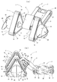
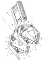
本発明の実施例を図面に沿って説明する。図1(a)(b)は本発明によるクローラロボットにおいて、特に2つのリンクを回動自在に結合した1節リンクを用いた際の、種々の作動態様の内の1つの作動態様をなす斜視図であり、このクローラロボット1は後述するように両側に三角クローラを備えた三角クローラ装置2と、両側に標準型の小型のクローラを備えた従属クローラ装置3と、両者を連結する1節リンク4とから構成される。
Embodiments of the present invention will be described with reference to the drawings. 1 (a) and 1 (b) are perspective views showing one operation mode among various operation modes in the crawler robot according to the present invention, particularly when a one-joint link in which two links are rotatably connected is used. The
三角クローラ装置2は、中心支軸11の両端が三角形をなす内側三角フレーム12と外側三角フレーム13からなるフレームに支持され、フレームの各頂点部分にはローラ14を備えている。各ローラにはゴム等の弾性体からなり無限機動帯としての弾性クローラ15を掛けており、通常状態では全体として三角形の三角クローラを構成している。三角クローラを支持する3個のローラ14の内、少なくとも一つがモータによって駆動されることにより、弾性クローラ15は各ローラ14の周りを三角形状に循環移動し、弾性クローラ15が接地している面における摩擦力によって前進或いは後退、更には停止することができるようになる。
The
その際、片側の第1三角クローラ16と、他側の第2三角クローラ17とを独自に駆動可能とし、クローラの循環を同方向、逆方向、更には片側を停止して、他側を前進或いは後退方向に移動可能とする。各三角クローラを駆動するローラ14の少なくとも1つはモータによって駆動されるが、図示実施例では図中示されていないが外側三角フレーム13と内側三角フレーム12間の両フレーム内部に配置されている。また、各ローラ14の支軸21は内側三角フレーム12と外側三角フレーム13に形成した放射状の案内溝22内で移動可能とし、位置調節等を可能としている。外側三角フレーム13の外側には、支軸11に対して回転自在な第1センサケース18及び第2センサケース19が配置されており、周辺を触覚センサも兼ねたガード20によって保護している。センサケースを外側に配置することで、作業や環境に適したセンサケース、もしくは作業用アーム等への交換を容易としている。
At this time, the first
中心支軸11の中間部には、図示の例では1節リンク4を構成する第1アーム23の一端が回動自在に支持されている。第1アーム23の他端には第2アーム24を回動自在に支持しており、第1アーム23に対して第2アーム24を内部の連結軸を中心に、モータにより任意に回転可能とし、それにより1節リンク4を構成している。図示実施例では第1アーム23と第2アーム24とが所定の範囲で回動できるように、第2アーム24の端部両側に支持アーム25、26を設け、それにより両アーム間に回動空間を形成し、両支持アーム25、26の先端に設けた回転軸に第1アーム23を回動可能に支持している。
In the illustrated example, one end of the
第2アーム24の他端には、従来から広く用いられている少なくとも2個のローラ間にクローラを巻き掛けた、標準型で小型の第1標準クローラ27と第2標準クローラ28を両側に備えた従属クローラ装置3における、前側軸29を回動自在に支持している。従属クローラ装置3は第2アーム24に対して、第2アーム24の他端内部に配置された連結軸29に直結の図示されていないモータにより任意に回転可能としている。第1標準クローラ27と第2標準クローラ28は共に、1節リンク4と連結する前側軸29に設けたローラ30と、後側軸31に設けたローラ32との間に巻き掛けられ、図示されていない後側軸31に直結のモータにより、従来のものと同様に作動させることができる。
At the other end of the
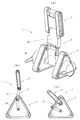
上記のような構造からなるクローラロボット1は図2〜図9に示すような種々の態様で作動可能な多自由度ロボットとすることができる。図2に示す作動態様においてはその骨格を同図(b)に示すように、三角クローラ装置2の中心支軸11から延びる1節リンク4の第1アーム23を、三角クローラ装置2の第1角部35側に回動し、第2アーム24を1節リンク4の節をなす回動軸36を中心に屈曲し、従動クローラ体3を支持する端部を三角クローラ装置2の第2角部37側に回動し、従属クローラ装置3は第2アーム24に支持される前側軸29から後側軸31を、三角クローラ装置2の第3角部38側に位置するように回動しており、それにより1節リンク4と従動クローラ体3は全て、三角クローラ装置2の外周縁の内側に収納した状態となる。その結果このクローラロボット1は全体として最もコンパクトな形態で、三角クローラ装置2のクローラの駆動により、前進、後退、回転等任意の移動を行うことができる。
The
図3に示す作動態様においては、三角クローラ装置2が1節クランク4を介して従動クローラ装置3を上方に支持した状態を示し、同図(a)の斜視図、及び同図(b)の模式図に示す例においては、三角クローラ装置2に対して1節クランク4を延ばして、従動クローラ装置3を支持し、従動クローラ装置3も上方に延ばして、クローラロボットがほぼ最も高い状態を示している。このような態様から更に同図(c)に示すように、1節クランクを屈曲させ、従動クローラ3を同様に屈曲させて支持することにより、全体として高さを低くした状態で、三角クローラ装置2により従動クローラ3を上方に支持して移動することができるようになる。
3 shows a state in which the
図4に示す作動態様においては図3の作動態様とは逆に、従動クローラ3の上方に三角クローラ装置2を支持して移動することができるようにした例を示している。即ち、従動クローラ装置3を通常の走行態様とした状態で1節クランク4の第2アーム24を充分後方に折り曲げ、第1アームを略上方に支持し、それにより三角クローラ装置2の重心を従動クローラ装置3の重心の略直上に位置させ、安定した状態で従動クローラ装置3によって任意の走行を行うことができるようにする。それにより、三角クローラ装置2の走行が不能となったときには、従動クローラ装置3によって走行可能となり、更にその他の各種作動を行うことができるようになる。
4 shows an example in which the
図5に示す作動態様においては、図4に示す作動態様における従動クローラ装置3による三角クローラ装置2の支持の状態で階段状構造物40に走行し、三角クローラ装置2を1節クランク4の伸張により上方に持ち上げ、階段状構造物40の第1段部41に載置した状態を示している。この状態から三角クローラ装置2が1節リンク4を反転して折り畳むようにして回動すると、三角クローラ装置2の重量が従動クローラ装置3より充分大きいため、従動クローラ装置3を持ち上げて第1段部41に載置する作動を行うことができる。これを繰り返すことで、各種の障害物を乗り越えて移動することができる。
In the operation mode shown in FIG. 5, the
図6に示す作動態様においては、図1に示す作動態様と同様の作動を行うことにより低い段差39に走行し、三角クローラ装置2を支軸11を中心に回転させ、クローラ接地面前方を持ち上げることで段差39を乗り越えて移動することができる。
In the operation mode shown in FIG. 6, the vehicle travels to a
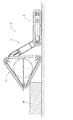
図5に示す作動態様においては、第1段部41が比較的低いため前記のような作動を行うことができたが、例えば図7に示すように構造物43の上部、或いは段部44が比較的高い場合において、従動クローラ装置3が全面接地しているときには三角クローラ装置2を単に持ち上げただけでは、三角クローラ装置2を図5に示す作動態様では段部44に載置することができないことがある。その点、図7に示した態様においては、従動クローラ装置3の前進移動による壁45側への付勢力によって、三角クローラ装置2を構造物43の壁45に押し付け、グリップしながら三角クローラ装置2を図7(a)の矢印A方向に駆動して、垂直壁45を上昇する移動を行わせ、同時に従動クローラ装置3を矢印B方向に駆動して前進させることにより、三角クローラ装置2は垂直壁45を上方に移動することができる。その結果同図(b)のように三角クローラ装置2は構造物43の段部44上に移動させることができる。更に必要に応じてこの状態から三角クローラ装置2が1節リンク4を図中C方向に反転回動することにより、従動クローラ装置3を持ち上げて段部44上に移動させ、クローラロボット1全体を段部44に移動させることができる。
In the operation mode shown in FIG. 5, since the
前記各実施例においては、三角クローラ装置2は単に三角フレームの形状に沿って弾性クローラを走行させた例を示したが、三角フレーム内において三角形の各辺の中間位置に伸縮自在にクローラガイド46を配置し、これを図8に示すように三角フレームから突出させて弾性クローラ15を伸張させることによって、六角形のクローラロボットとすることができ、この状態で中心支軸11を中心に三角フレーム12、13自体を回転させることにより、車輪と同様に回転駆動することができ、特に大きな直径の車輪と同様に高速移動が可能となる。この時には従動クローラ装置3は走行駆動を行う必要はないが、前記図2の作動態様のように三角フレームの外周縁内に収納した状態とすることにより、更なる高速移動が可能となる。また、更に多数のクローラガイド46を設けることにより、より円形に近い形状にすることもできる。なお、このような態様においても、クローラを駆動することによる移動も可能である。
In each of the above-described embodiments, the
前記各実施例においては、三角クローラ装置2、従動クローラ装置3、これらを連結する1節リンク4からなるクローラロボット1単体での作動態様について述べたが、それ以外に例えば図9に示すように、クローラロボット単体を複数数珠繋ぎに連結して、蛇のように長い移動ロボット構造を実現することができる。このような連結のためには、図9において最後尾の従動クローラ装置に示すように、後側軸31に左右のフック47を回動自在に設け、通常時は従動クローラ装置内に回動して収納し、連結の必要時には図示のように後方に回動させ、後続のクローラロボットにおける三角クローラ装置2の中心支軸11等に引っ掛けて連結する。なお、このような連結手段は周知の技術を利用して更に種々の態様で実施することができる。
In each of the above-described embodiments, the operation mode of the
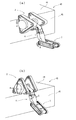
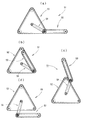
前記実施例においては本発明の好ましい例として、三角クローラ装置2と従動クローラ装置3とを、第1リンクと第2リンクを回動自在に連結した1節リンク4により接続した例を示したが、三角クローラ装置と従動クローラ装置とを接続するには各種のリンク、或いは同等の物体であれば良く、例えば図10に示すように1つのリンク54によって連結しても、前記実施例と同様に種々の態様で作動させることができる。図10(a)に示す例においては、前記図1と同様の作動態様を示し、クローラロボット51は三角クローラ装置52と従動クローラ装置53とがリンク54によって連結され、両者共に接地している状態を示している。
In the above embodiment, as a preferred example of the present invention, an example in which the
図10(b)に示す例においては、前記図2と同様の作動態様を示し、三角クローラ装置52の外周縁内にリンク54及び従動クローラ装置53とが収納された状態を示している。図10(c)に示す例においては、前記図3と同様の作動態様を示し、三角クローラ装置52に対して従動クローラ装置53を持ち上げた状態を示している。図10(d)に示す例においては、前記図4と同様の作動態様を示し、従動クローラ装置53によって三角クローラ装置52を持ち上げた状態を示している。このような作動態様によって、更に前記図5、図7と同様の作動を行うことができる。更にこのクローラロボット51においても、前記図8及び図9の作動を行うことができるのはいうまでもない。
In the example shown in FIG. 10B, the operation mode similar to that of FIG. 2 is shown, and a state where the
前記実施例においては三角クローラ装置と従動クローラ装置とを1節リンク、或いは単なるリンクにより連結した例を示したが、その他2節、3節等のリンクを用いても良く、リンクを任意に伸縮自在に構成しても良い。また、図8に示すような作動態様を行う必要がない場合は、クローラとして鋼帯のほか各種素材の帯状の材料を用いることができる。本発明者等は現在までに、高さ20cmの図1に示すような三角クローラ装置を用いたクローラロボットを製作し、種々の作動を行った結果、遠隔操作による前後左右への移動、その場での回転、32cmの段差越え、階段昇降実験に成功している。 In the above-described embodiment, the triangular crawler device and the driven crawler device are connected by a one-link or a simple link. However, other links such as two- and three-nodes may be used, and the link can be arbitrarily expanded and contracted. You may comprise freely. Moreover, when it is not necessary to perform an operation | movement aspect as shown in FIG. 8, the strip | belt-shaped material of various raw materials other than a steel strip can be used as a crawler. The present inventors have manufactured a crawler robot using a triangular crawler device as shown in FIG. 1 having a height of 20 cm and have performed various operations so far. We have succeeded in rotating the stairs, going over the step of 32cm, and going up and down the stairs.
上記のような本発明は、例えば三角クローラの高さが20cm程度でも32cmの段差を乗り越えることができ、人が通常移動する範囲の段差は乗り越えることができるとともに構造が小型であるため、クローラロボット単体として、或いは複数クローラロボット間の無線を利用した情報連携により、例えば以下のような用途に広く用いることができる。
A.クローラロボット単体としての用途:
・ 夜間のデパート、オフィスビル、美術館、博物館などの巡回警備
・ ホームセキュリティー等の侵入監視用ロボット
・ ショールーム内、アミューズメントパーク内のナビゲーション
・ 弱視者や老齢者の歩行補助
・ センサ種類などと適宜変更し、教育用プラットフォームとしての利用
B.複数クローラロボット間の無線を利用した情報連携による用途:
・ デパート、地下街、地下鉄ホーム等の公共エリアにおける災害、テロ発生時の情報収集
・ 大規模ファームにおけるフィールドデータ収集
・ 金属探知センサ等を適宜追加して、地雷源探査、除去
・ 津波、地震災害後の人命捜索
In the present invention as described above, for example, even if the height of the triangular crawler is about 20 cm, the step of 32 cm can be overcome, the step in the range in which a person normally moves can be overcome, and the structure is small. For example, it can be widely used for the following purposes as a single unit or by information linkage using wireless between a plurality of crawler robots.
A. Use as a crawler robot alone:
・ Night guards for department stores, office buildings, museums, museums, etc. ・ Robots for intrusion monitoring such as home security ・ Navigation in showrooms and amusement parks ・ Walking assistance for low-sighted people and elderly people ・ Sensor types, etc. Use as an educational platform Uses for information linkage using wireless between multiple crawler robots:
・ Collecting information in the event of a disaster or terrorism in public areas such as department stores, underground malls, subway platforms, etc. ・ Collecting field data in large-scale farms ・ Exploring and removing landmine sources by adding metal detection sensors, etc. Life search
1 クローラロボット
2 三角クローラ装置
3 従動クローラ装置
4 1節リンク
11 中心支軸
12 内側三角フレーム
13 外側三角フレーム
14 ローラ
15 弾性クローラ
16 第1三角クローラ
17 第2三角クローラ
18 第1センサケース
19 第2センサケース
20 ガード
21 支軸
22 案内溝
23 第1アーム
24 第2アーム
25 支持アーム
26 支持アーム
27 第1標準クローラ
28 第2標準クローラ
29 前側軸
30 ローラ
31 後側軸
32 ローラ
DESCRIPTION OF
Claims (12)
2個のローラの間にクローラを巻き掛けた第1及び第2の標準クローラにより従動クローラ装置を構成し、
前記三角クローラ装置の支軸と前記従動クローラ装置とをリンクの両端に回動自在に連結し、前記三角クローラ装置の外周縁内に前記リンク及び前記従動クローラ装置が収納されるように構成したことを特徴とするクローラロボット。 Provided with the first and second triangular crawler wound around rollers disposed at each apex of the frame forming a triangle on both sides, the center of both frames linked by a support shaft constitute a triangular crawler device,
A driven crawler device is constituted by first and second standard crawlers in which a crawler is wound between two rollers ,
Said the a support shaft of the triangular crawler device and the subordinate crawler device rotatably connected to both ends of the link, and configured the as the inside peripheral edge of the triangular crawler device link and the subordinate crawler device are accommodated Crawler robot.
The crawler robot according to claim 1, wherein the driven crawler device is provided with a connecting means for connecting to another crawler robot so that a plurality of crawler robots can be connected in a daisy chain.
Priority Applications (5)
| Application Number | Priority Date | Filing Date | Title |
|---|---|---|---|
| JP2006064991A JP4635259B2 (en) | 2006-03-10 | 2006-03-10 | Crawler robot |
| AT07250985T ATE489279T1 (en) | 2006-03-10 | 2007-03-09 | TRACKER ROBOT |
| DE602007010684T DE602007010684D1 (en) | 2006-03-10 | 2007-03-09 | tracked robot |
| US11/715,927 US7793743B2 (en) | 2006-03-10 | 2007-03-09 | Crawler robot |
| EP07250985A EP1832501B1 (en) | 2006-03-10 | 2007-03-09 | Crawler robot |
Applications Claiming Priority (1)
| Application Number | Priority Date | Filing Date | Title |
|---|---|---|---|
| JP2006064991A JP4635259B2 (en) | 2006-03-10 | 2006-03-10 | Crawler robot |
Publications (2)
| Publication Number | Publication Date |
|---|---|
| JP2007237991A JP2007237991A (en) | 2007-09-20 |
| JP4635259B2 true JP4635259B2 (en) | 2011-02-23 |
Family
ID=38137498
Family Applications (1)
| Application Number | Title | Priority Date | Filing Date |
|---|---|---|---|
| JP2006064991A Expired - Lifetime JP4635259B2 (en) | 2006-03-10 | 2006-03-10 | Crawler robot |
Country Status (5)
| Country | Link |
|---|---|
| US (1) | US7793743B2 (en) |
| EP (1) | EP1832501B1 (en) |
| JP (1) | JP4635259B2 (en) |
| AT (1) | ATE489279T1 (en) |
| DE (1) | DE602007010684D1 (en) |
Families Citing this family (65)
| Publication number | Priority date | Publication date | Assignee | Title |
|---|---|---|---|---|
| EP2112963B1 (en) * | 2006-10-06 | 2018-05-30 | iRobot Defense Holdings, Inc. | Robotic vehicle with tracks and flippers |
| US7654348B2 (en) | 2006-10-06 | 2010-02-02 | Irobot Corporation | Maneuvering robotic vehicles having a positionable sensor head |
| US7891446B2 (en) * | 2006-10-06 | 2011-02-22 | Irobot Corporation | Robotic vehicle deck adjustment |
| CN101626946B (en) | 2006-11-13 | 2013-06-05 | 雷神萨科斯公司 | Suspension system for light robot vehicle and the vehicle support method |
| DE602007007807D1 (en) | 2006-11-13 | 2010-08-26 | Raytheon Sarcos Llc | VERSATILE USEFUL BAND FOR LIGHTWEIGHT MOBILE ROBOTS |
| CN102141181B (en) * | 2006-11-13 | 2014-10-08 | 雷神萨科斯公司 | Serpentine robotic crawler |
| EP2476604B1 (en) * | 2006-11-13 | 2013-08-21 | Raytheon Company | Tracked robotic crawler having a moveable arm |
| JP4237249B2 (en) * | 2007-01-25 | 2009-03-11 | トピー工業株式会社 | Crawler device and its automatic attitude control. |
| WO2008137953A1 (en) | 2007-05-07 | 2008-11-13 | Raytheon Sarcos, Llc | Method for manufacturing a complex structure |
| US7874386B2 (en) * | 2007-05-11 | 2011-01-25 | Pinhas Ben-Tzvi | Hybrid mobile robot |
| GB2489146B (en) * | 2007-07-02 | 2012-11-21 | Hobbs Ind Ltd | A wall tie |
| CN101784435B (en) | 2007-07-10 | 2013-08-28 | 雷神萨科斯公司 | Modular robotic crawler |
| JP5384031B2 (en) * | 2008-05-26 | 2014-01-08 | 大和ハウス工業株式会社 | Step-crawler-type traveling vehicle device |
| US7926598B2 (en) | 2008-12-09 | 2011-04-19 | Irobot Corporation | Mobile robotic vehicle |
| US8392036B2 (en) | 2009-01-08 | 2013-03-05 | Raytheon Company | Point and go navigation system and method |
| US8317555B2 (en) | 2009-06-11 | 2012-11-27 | Raytheon Company | Amphibious robotic crawler |
| US8935014B2 (en) | 2009-06-11 | 2015-01-13 | Sarcos, Lc | Method and system for deploying a surveillance network |
| CN102802881B (en) * | 2010-01-14 | 2015-12-16 | 工程服务公司 | Mobile robot |
| CN102198655B (en) * | 2010-03-22 | 2013-04-03 | 常州机械电子工程研究所 | Search and rescue robot |
| CN101973320B (en) * | 2010-09-21 | 2012-06-13 | 上海大学 | Simulation wriggling walking device |
| US20120183383A1 (en) * | 2010-09-26 | 2012-07-19 | Rustam Stolkin | Mechanism and method of operation for polymorphic tracked vehicles such that the vehicle's weight can be spread between multiple supporting wheels |
| WO2012044663A1 (en) * | 2010-09-30 | 2012-04-05 | Schlee Keith L | Multi-unit mobile robot |
| US10315715B2 (en) * | 2010-11-08 | 2019-06-11 | James Beard | Mobile, climbing endless track robotic system to perform remote inspections on structures |
| US9522595B2 (en) | 2011-01-27 | 2016-12-20 | Irobot Defense Holdings, Inc. | Small unmanned ground vehicle |
| US9346499B2 (en) | 2011-01-27 | 2016-05-24 | Irobot Corporation | Resilient wheel assemblies |
| RU2472662C1 (en) * | 2011-06-22 | 2013-01-20 | Геннадий Феофанович Мамарин | Transport facility caterpillar propulsor to overcome scarp, counterscarp and stair flights |
| CN102390444A (en) * | 2011-10-24 | 2012-03-28 | 上海电力学院 | Adaptive ground emergency rescue aided robot |
| CN102514640B (en) * | 2011-12-07 | 2013-11-06 | 宁波大学 | A Transformable Rescue Robot |
| TW201339034A (en) * | 2012-03-30 | 2013-10-01 | Rui-Ren Zhou | Stair climbing mechanism of moving vehicle |
| US9248875B2 (en) * | 2012-04-17 | 2016-02-02 | Robo-team Ltd. | Driving flipper with robotic arm |
| US8393422B1 (en) | 2012-05-25 | 2013-03-12 | Raytheon Company | Serpentine robotic crawler |
| US20140031977A1 (en) | 2012-07-27 | 2014-01-30 | Engineering Services Inc. | Modular mobile robot |
| US8434576B1 (en) | 2012-08-21 | 2013-05-07 | Andrew Ferguson | Mobile reconnaissance apparatus with articulating traction control |
| US9031698B2 (en) | 2012-10-31 | 2015-05-12 | Sarcos Lc | Serpentine robotic crawler |
| CN103110487B (en) * | 2013-03-18 | 2015-08-26 | 王永军 | The amphibious obstacle-free intelligent robot wheel chair in a kind of terraced land |
| DE102013006692B4 (en) * | 2013-04-16 | 2020-10-01 | Iav Gmbh Ingenieurgesellschaft Auto Und Verkehr | Universal autonomous chassis for transporting functional and load bearing devices |
| CN103318288A (en) * | 2013-06-03 | 2013-09-25 | 上海大学 | Synchronous belt driving type full tracked robot |
| ITTO20130544A1 (en) | 2013-07-01 | 2015-01-02 | Oto Melara Spa | FRAME FOR A TERRESTRIAL VEHICLE WITHOUT CREW ON BOARD OR UGV. |
| US9409292B2 (en) | 2013-09-13 | 2016-08-09 | Sarcos Lc | Serpentine robotic crawler for performing dexterous operations |
| CN103863424B (en) * | 2014-02-26 | 2017-11-28 | 南昌大学 | Adapt to the crusing robot of complicated unstructured landform |
| US9566711B2 (en) | 2014-03-04 | 2017-02-14 | Sarcos Lc | Coordinated robotic control |
| JP6463621B2 (en) * | 2014-11-20 | 2019-02-06 | 株式会社 日立産業制御ソリューションズ | Traveling device |
| US9809264B1 (en) * | 2015-07-20 | 2017-11-07 | The United States Of America, As Represented By The Secretary Of The Navy | Track kit for two wheeled balancing ground vehicle |
| US10071303B2 (en) | 2015-08-26 | 2018-09-11 | Malibu Innovations, LLC | Mobilized cooler device with fork hanger assembly |
| US10807659B2 (en) | 2016-05-27 | 2020-10-20 | Joseph L. Pikulski | Motorized platforms |
| CN105539614B (en) * | 2015-12-18 | 2017-07-21 | 哈尔滨科能熔敷科技有限公司 | Utilize the water cooling wall-climbing robot of mathematical modeling Multipoint synchronous thickness measuring |
| JP6503402B2 (en) * | 2016-08-02 | 2019-04-17 | 必飛有限公司B−Free Limited | Track type moving device |
| WO2018027219A1 (en) * | 2016-08-05 | 2018-02-08 | Irobot Defense Holdings, Inc. | Unmanned ground vehicle with compact manipulator stowing |
| US10471589B2 (en) | 2016-09-20 | 2019-11-12 | Foster-Miller, Inc. | Remotely controlled packable robot |
| US10414039B2 (en) | 2016-09-20 | 2019-09-17 | Foster-Miller, Inc. | Remotely controlled packable robot |
| WO2018154424A1 (en) | 2017-02-21 | 2018-08-30 | Induna Robotics (Pty) Ltd | Robotic limb arrangement and associated robot |
| US10889340B2 (en) | 2017-07-07 | 2021-01-12 | Foster-Miller, Inc. | Remotely controlled packable robot with folding tracks |
| CN108633455B (en) * | 2018-03-23 | 2022-01-28 | 华南农业大学 | Triangular crawler type sectional sugarcane combine harvester |
| CN109050693B (en) * | 2018-07-11 | 2024-02-02 | 济南大学 | Step-up device with following function and implementation method thereof |
| US11331818B2 (en) | 2018-10-11 | 2022-05-17 | Foster-Miller, Inc. | Remotely controlled packable robot |
| CN109131613A (en) * | 2018-10-12 | 2019-01-04 | 安徽工程大学 | A kind of full landform transportation robot and its control method |
| CN109850023A (en) * | 2019-03-05 | 2019-06-07 | 内蒙古第一机械集团股份有限公司 | A kind of planetary triangle crawler travel and driving device |
| CN109955927A (en) * | 2019-04-24 | 2019-07-02 | 重庆科技学院 | A walking system of intelligent mobile robot adaptive to complex 3D metal surface |
| CN110978919B (en) * | 2019-12-18 | 2023-07-14 | 威海多鱼海洋科技有限公司 | Crawler-type marine organism fishing robot |
| CN111345949B (en) * | 2020-01-07 | 2020-12-22 | 重庆大学 | A kind of automatic stair climbing device, control method and wheelchair |
| JP7437622B2 (en) * | 2020-03-13 | 2024-02-26 | 株式会社リコー | traveling device |
| CN111872915A (en) * | 2020-07-14 | 2020-11-03 | 重庆大学 | Obstacle-surmounting exploration robot based on oscillating crawler wheels |
| US12311550B2 (en) | 2020-12-31 | 2025-05-27 | Sarcos Corp. | Smart control system for a robotic device |
| TR2021019459A2 (en) * | 2021-12-09 | 2023-06-21 | Havelsan Hava Elektronik Sanayi Ve Ticaret Anonim Sirketi | CAVE AND RESIDENTIAL UNMANNED GROUND VEHICLE |
| WO2024251314A1 (en) * | 2023-06-06 | 2024-12-12 | České vysoké učení technické v Praze | Robotic vehicle chassis with independently controllable triangular tracks and tactile perception of terrain shape and compliance |
Family Cites Families (34)
| Publication number | Priority date | Publication date | Assignee | Title |
|---|---|---|---|---|
| US2751027A (en) * | 1952-05-19 | 1956-06-19 | Robert B Mclaughlin | Endless track supported invalid chair |
| GB844768A (en) | 1955-10-10 | 1960-08-17 | Johann Wilhelm Ludowici | Improvements in or relating to endless track units for vehicles |
| US3414072A (en) * | 1965-09-16 | 1968-12-03 | Lockheed Aircraft Corp | Vehicle capable of articulating about roll, pitch, and yaw axes |
| US3417832A (en) * | 1966-10-24 | 1968-12-24 | William B Jaspert | Wheeled vehicle selectively convertible to endless track vehicle |
| CH542069A (en) * | 1970-09-24 | 1973-09-30 | Sig Schweiz Industrieges | Vehicle with passenger seats |
| US3730287A (en) * | 1971-05-17 | 1973-05-01 | Nasa | Vehicle for use in planetary exploration |
| JPS58191673A (en) | 1982-05-04 | 1983-11-08 | Mitsubishi Heavy Ind Ltd | Running device |
| JPS58224870A (en) * | 1982-06-24 | 1983-12-27 | Toshiba Corp | Travel gear |
| JPS5918072A (en) * | 1982-07-20 | 1984-01-30 | Toshiba Corp | Travelling machine |
| JPS5997178U (en) * | 1982-12-21 | 1984-07-02 | 株式会社小松製作所 | Track type traveling device |
| CA1245510A (en) * | 1984-03-05 | 1988-11-29 | Arktos Developments Ltd. | All terrain vehicle and method of operating same |
| JPS6167678A (en) * | 1984-09-10 | 1986-04-07 | Mitsubishi Electric Corp | Shifter |
| JPS61160366A (en) | 1984-12-30 | 1986-07-21 | Shinwa Seisakusho:Kk | Loading platform adjusting equipment for cart |
| JPS61222879A (en) | 1985-03-29 | 1986-10-03 | Kobe Steel Ltd | Traveling device |
| FR2583701B1 (en) * | 1985-06-21 | 1990-03-23 | Commissariat Energie Atomique | VARIABLE GEOMETRY CRAWLER VEHICLE |
| JPS6379282U (en) | 1986-11-12 | 1988-05-25 | ||
| JPH01132475A (en) * | 1987-11-14 | 1989-05-24 | Aisin Aw Co Ltd | Double belt pulley mechanism |
| JPH0333484U (en) * | 1989-08-09 | 1991-04-02 | ||
| WO1992002398A1 (en) * | 1990-08-08 | 1992-02-20 | Kabushiki Kaisha Komatsu Seisakusho | Disaster relief robot and its operation controller |
| IL98207A (en) * | 1991-05-22 | 1994-08-26 | Israel Aircraft Ind Ltd | Wheelchair with apparatus for assisting travel on a surface not suitable for wheeled travel |
| JP2580542B2 (en) | 1994-11-14 | 1997-02-12 | 防衛庁技術研究本部長 | Flexible crawler with rice ball mechanism |
| US5650579A (en) | 1995-12-05 | 1997-07-22 | General Electric Company | Miniature air gap inspection crawler |
| JPH09226637A (en) | 1996-02-28 | 1997-09-02 | Suzuki Motor Corp | Crawler device and traveling vehicle using the same |
| JP3692602B2 (en) | 1996-03-08 | 2005-09-07 | スズキ株式会社 | Traveling vehicle |
| JPH10236345A (en) * | 1997-02-26 | 1998-09-08 | Showa Aircraft Ind Co Ltd | Special traveling vehicles |
| US6571893B2 (en) * | 1997-12-22 | 2003-06-03 | Yozmot Gfanot Initiative Center | Light vehicle for sporting and off-road biking |
| US6523629B1 (en) * | 1999-06-07 | 2003-02-25 | Sandia Corporation | Tandem mobile robot system |
| JP4142496B2 (en) * | 2002-07-29 | 2008-09-03 | 耕一 岡本 | Car going up and down stairs |
| US7017687B1 (en) * | 2002-11-21 | 2006-03-28 | Sarcos Investments Lc | Reconfigurable articulated leg and wheel |
| JP4264504B2 (en) | 2003-01-22 | 2009-05-20 | 消防庁長官 | Polyhedron moving device having shape change mechanism |
| US6837318B1 (en) * | 2003-03-28 | 2005-01-04 | Hanna Craig | Rescue and exploration apparatus |
| DE20314213U1 (en) | 2003-09-12 | 2003-11-20 | Ebisch, Siegfried, 08236 Ellefeld | A stepping ground travelling robot has two endless tracked drive units linked by struts and a pivot enabling one unit to be lifted over obstacles |
| JP4021907B2 (en) | 2004-04-27 | 2007-12-12 | 直 石嶺 | Traveling device |
| JP4721461B2 (en) | 2004-04-30 | 2011-07-13 | コリア インスティテュート オブ サイエンス アンド テクノロジー | Link type double truck device for traveling |
-
2006
- 2006-03-10 JP JP2006064991A patent/JP4635259B2/en not_active Expired - Lifetime
-
2007
- 2007-03-09 AT AT07250985T patent/ATE489279T1/en not_active IP Right Cessation
- 2007-03-09 EP EP07250985A patent/EP1832501B1/en not_active Not-in-force
- 2007-03-09 DE DE602007010684T patent/DE602007010684D1/en active Active
- 2007-03-09 US US11/715,927 patent/US7793743B2/en not_active Expired - Fee Related
Also Published As
| Publication number | Publication date |
|---|---|
| JP2007237991A (en) | 2007-09-20 |
| EP1832501B1 (en) | 2010-11-24 |
| US7793743B2 (en) | 2010-09-14 |
| DE602007010684D1 (en) | 2011-01-05 |
| EP1832501A2 (en) | 2007-09-12 |
| EP1832501A3 (en) | 2007-11-28 |
| ATE489279T1 (en) | 2010-12-15 |
| US20070209844A1 (en) | 2007-09-13 |
Similar Documents
| Publication | Publication Date | Title |
|---|---|---|
| JP4635259B2 (en) | Crawler robot | |
| JP4607442B2 (en) | Crawler type traveling robot | |
| JP4719866B2 (en) | Mobile device | |
| JP4181040B2 (en) | Adaptive traction system for vehicles | |
| JP5179138B2 (en) | Multi-leg type traveling device | |
| US20130081885A1 (en) | Transformability(TM): personal mobility with shape-changing wheels | |
| CN106184434B (en) | Wheel carries out transformation mobile chassis and the fire-fighting sniffing robot with it | |
| JP5467423B2 (en) | Step-over wheels and wheel type robots | |
| KR101094740B1 (en) | Mobile robot | |
| CN212497797U (en) | A multifunctional obstacle rescue vehicle | |
| CN111923058A (en) | A multifunctional obstacle rescue vehicle | |
| JPH08133141A (en) | Flexible crawler with rice ball mechanism | |
| JPH0966855A (en) | Crawler vehicle | |
| CN102490803B (en) | Wheel-type linked barrier-crossing traveling mechanism | |
| JPH0632263A (en) | Legged moving vehicle | |
| KR20170135696A (en) | Track system for moving apparatus for driving over step barrier | |
| CN103318279B (en) | Wheel crawler belt mobile device | |
| JP6358731B2 (en) | Wheel type moving body and wheelchair | |
| TWM492845U (en) | An apparatus for assisting parking | |
| CN110271622A (en) | Wheel-foot structure and wheel-foot robot | |
| JPS6323954B2 (en) | ||
| JP3141156B2 (en) | Moving vehicle tires | |
| KR20160003497A (en) | Mobile platform of robot equipped with flipper | |
| JP2604112B2 (en) | Omnidirectional vehicle | |
| KR100811860B1 (en) | Overcome obstacles robot |
Legal Events
| Date | Code | Title | Description |
|---|---|---|---|
| A621 | Written request for application examination |
Free format text: JAPANESE INTERMEDIATE CODE: A621 Effective date: 20080327 |
|
| A977 | Report on retrieval |
Free format text: JAPANESE INTERMEDIATE CODE: A971007 Effective date: 20100527 |
|
| A131 | Notification of reasons for refusal |
Free format text: JAPANESE INTERMEDIATE CODE: A131 Effective date: 20100622 |
|
| A521 | Request for written amendment filed |
Free format text: JAPANESE INTERMEDIATE CODE: A523 Effective date: 20100811 |
|
| TRDD | Decision of grant or rejection written | ||
| A01 | Written decision to grant a patent or to grant a registration (utility model) |
Free format text: JAPANESE INTERMEDIATE CODE: A01 Effective date: 20101102 |
|
| A01 | Written decision to grant a patent or to grant a registration (utility model) |
Free format text: JAPANESE INTERMEDIATE CODE: A01 |
|
| A61 | First payment of annual fees (during grant procedure) |
Free format text: JAPANESE INTERMEDIATE CODE: A61 Effective date: 20101104 |
|
| FPAY | Renewal fee payment (event date is renewal date of database) |
Free format text: PAYMENT UNTIL: 20131203 Year of fee payment: 3 |
|
| R150 | Certificate of patent or registration of utility model |
Ref document number: 4635259 Country of ref document: JP Free format text: JAPANESE INTERMEDIATE CODE: R150 Free format text: JAPANESE INTERMEDIATE CODE: R150 |
|
| FPAY | Renewal fee payment (event date is renewal date of database) |
Free format text: PAYMENT UNTIL: 20131203 Year of fee payment: 3 |
|
| R250 | Receipt of annual fees |
Free format text: JAPANESE INTERMEDIATE CODE: R250 |
|
| R250 | Receipt of annual fees |
Free format text: JAPANESE INTERMEDIATE CODE: R250 |
|
| S533 | Written request for registration of change of name |
Free format text: JAPANESE INTERMEDIATE CODE: R313533 |
|
| R350 | Written notification of registration of transfer |
Free format text: JAPANESE INTERMEDIATE CODE: R350 |
|
| R250 | Receipt of annual fees |
Free format text: JAPANESE INTERMEDIATE CODE: R250 |
|
| R250 | Receipt of annual fees |
Free format text: JAPANESE INTERMEDIATE CODE: R250 |
|
| R250 | Receipt of annual fees |
Free format text: JAPANESE INTERMEDIATE CODE: R250 |
|
| R250 | Receipt of annual fees |
Free format text: JAPANESE INTERMEDIATE CODE: R250 |
|
| R250 | Receipt of annual fees |
Free format text: JAPANESE INTERMEDIATE CODE: R250 |
|
| R250 | Receipt of annual fees |
Free format text: JAPANESE INTERMEDIATE CODE: R250 |
|
| R250 | Receipt of annual fees |
Free format text: JAPANESE INTERMEDIATE CODE: R250 |
|
| R250 | Receipt of annual fees |
Free format text: JAPANESE INTERMEDIATE CODE: R250 |
|
| R250 | Receipt of annual fees |
Free format text: JAPANESE INTERMEDIATE CODE: R250 |
|
| R250 | Receipt of annual fees |
Free format text: JAPANESE INTERMEDIATE CODE: R250 |
|
| R250 | Receipt of annual fees |
Free format text: JAPANESE INTERMEDIATE CODE: R250 |