EP2082159B1 - Serpentine robotic crawler - Google Patents
Serpentine robotic crawler Download PDFInfo
- Publication number
- EP2082159B1 EP2082159B1 EP07870883.1A EP07870883A EP2082159B1 EP 2082159 B1 EP2082159 B1 EP 2082159B1 EP 07870883 A EP07870883 A EP 07870883A EP 2082159 B1 EP2082159 B1 EP 2082159B1
- Authority
- EP
- European Patent Office
- Prior art keywords
- actuated
- robotic crawler
- serpentine robotic
- wrist
- frame
- Prior art date
- Legal status (The legal status is an assumption and is not a legal conclusion. Google has not performed a legal analysis and makes no representation as to the accuracy of the status listed.)
- Active
Links
- WYTGDNHDOZPMIW-RCBQFDQVSA-N alstonine Natural products C1=CC2=C3C=CC=CC3=NC2=C2N1C[C@H]1[C@H](C)OC=C(C(=O)OC)[C@H]1C2 WYTGDNHDOZPMIW-RCBQFDQVSA-N 0.000 title claims description 93
- 230000033001 locomotion Effects 0.000 claims description 43
- 238000005452 bending Methods 0.000 claims description 31
- 238000004891 communication Methods 0.000 claims description 13
- 230000009194 climbing Effects 0.000 description 6
- 239000000463 material Substances 0.000 description 2
- 238000012986 modification Methods 0.000 description 2
- 230000004048 modification Effects 0.000 description 2
- 230000002459 sustained effect Effects 0.000 description 2
- 238000010168 coupling process Methods 0.000 description 1
- 230000007812 deficiency Effects 0.000 description 1
- 230000001419 dependent effect Effects 0.000 description 1
- 238000010586 diagram Methods 0.000 description 1
- 230000009977 dual effect Effects 0.000 description 1
- 230000007613 environmental effect Effects 0.000 description 1
- 231100001261 hazardous Toxicity 0.000 description 1
- 238000013507 mapping Methods 0.000 description 1
- 230000007246 mechanism Effects 0.000 description 1
- 238000000034 method Methods 0.000 description 1
- 238000012545 processing Methods 0.000 description 1
- 238000011160 research Methods 0.000 description 1
- 230000003068 static effect Effects 0.000 description 1
- 239000000126 substance Substances 0.000 description 1
- 239000000725 suspension Substances 0.000 description 1
- 238000004804 winding Methods 0.000 description 1
Images


Classifications
-
- F—MECHANICAL ENGINEERING; LIGHTING; HEATING; WEAPONS; BLASTING
- F16—ENGINEERING ELEMENTS AND UNITS; GENERAL MEASURES FOR PRODUCING AND MAINTAINING EFFECTIVE FUNCTIONING OF MACHINES OR INSTALLATIONS; THERMAL INSULATION IN GENERAL
- F16L—PIPES; JOINTS OR FITTINGS FOR PIPES; SUPPORTS FOR PIPES, CABLES OR PROTECTIVE TUBING; MEANS FOR THERMAL INSULATION IN GENERAL
- F16L55/00—Devices or appurtenances for use in, or in connection with, pipes or pipe systems
- F16L55/26—Pigs or moles, i.e. devices movable in a pipe or conduit with or without self-contained propulsion means
- F16L55/28—Constructional aspects
- F16L55/30—Constructional aspects of the propulsion means, e.g. towed by cables
- F16L55/32—Constructional aspects of the propulsion means, e.g. towed by cables being self-contained
-
- B—PERFORMING OPERATIONS; TRANSPORTING
- B62—LAND VEHICLES FOR TRAVELLING OTHERWISE THAN ON RAILS
- B62D—MOTOR VEHICLES; TRAILERS
- B62D55/00—Endless track vehicles
- B62D55/06—Endless track vehicles with tracks without ground wheels
- B62D55/065—Multi-track vehicles, i.e. more than two tracks
-
- B—PERFORMING OPERATIONS; TRANSPORTING
- B62—LAND VEHICLES FOR TRAVELLING OTHERWISE THAN ON RAILS
- B62D—MOTOR VEHICLES; TRAILERS
- B62D55/00—Endless track vehicles
- B62D55/06—Endless track vehicles with tracks without ground wheels
- B62D55/065—Multi-track vehicles, i.e. more than two tracks
- B62D55/0655—Articulated endless track vehicles
-
- B—PERFORMING OPERATIONS; TRANSPORTING
- B62—LAND VEHICLES FOR TRAVELLING OTHERWISE THAN ON RAILS
- B62D—MOTOR VEHICLES; TRAILERS
- B62D55/00—Endless track vehicles
- B62D55/06—Endless track vehicles with tracks without ground wheels
- B62D55/07—Mono-track vehicles
-
- B—PERFORMING OPERATIONS; TRANSPORTING
- B62—LAND VEHICLES FOR TRAVELLING OTHERWISE THAN ON RAILS
- B62D—MOTOR VEHICLES; TRAILERS
- B62D57/00—Vehicles characterised by having other propulsion or other ground- engaging means than wheels or endless track, alone or in addition to wheels or endless track
- B62D57/04—Vehicles characterised by having other propulsion or other ground- engaging means than wheels or endless track, alone or in addition to wheels or endless track having other than ground-engaging propulsion means, e.g. having propellers
-
- F—MECHANICAL ENGINEERING; LIGHTING; HEATING; WEAPONS; BLASTING
- F16—ENGINEERING ELEMENTS AND UNITS; GENERAL MEASURES FOR PRODUCING AND MAINTAINING EFFECTIVE FUNCTIONING OF MACHINES OR INSTALLATIONS; THERMAL INSULATION IN GENERAL
- F16L—PIPES; JOINTS OR FITTINGS FOR PIPES; SUPPORTS FOR PIPES, CABLES OR PROTECTIVE TUBING; MEANS FOR THERMAL INSULATION IN GENERAL
- F16L2101/00—Uses or applications of pigs or moles
- F16L2101/30—Inspecting, measuring or testing
-
- Y—GENERAL TAGGING OF NEW TECHNOLOGICAL DEVELOPMENTS; GENERAL TAGGING OF CROSS-SECTIONAL TECHNOLOGIES SPANNING OVER SEVERAL SECTIONS OF THE IPC; TECHNICAL SUBJECTS COVERED BY FORMER USPC CROSS-REFERENCE ART COLLECTIONS [XRACs] AND DIGESTS
- Y10—TECHNICAL SUBJECTS COVERED BY FORMER USPC
- Y10T—TECHNICAL SUBJECTS COVERED BY FORMER US CLASSIFICATION
- Y10T74/00—Machine element or mechanism
- Y10T74/20—Control lever and linkage systems
- Y10T74/20207—Multiple controlling elements for single controlled element
- Y10T74/20305—Robotic arm
- Y10T74/20329—Joint between elements
Definitions
- the present invention relates to small, unmanned ground robotic vehicles. More particularly, the present invention relates to a serpentine robotic crawler having multiple tracked frame units interconnected through a high-degree of freedom actuated linkage.
- Robotics is an active area of research, and many different types of robotic vehicles have been developed for various tasks.
- unmanned aerial vehicles have been quite successful in military aerial reconnaissance.
- Less success has been achieved with unmanned ground vehicles, however, in part because the ground environment is significantly more difficult to traverse than the airborne environment.
- Unmanned ground vehicles face many challenges when attempting mobility.
- Terrain can vary widely, including for example, loose and shifting materials, obstacles, vegetation, limited width or height openings, steps, and the like.
- a vehicle optimized for operation in one environment may perform poorly in other environments.
- Legged robots can be agile, but use complex control mechanisms to move and achieve stability.
- Wheeled vehicles can provide high mobility, but provide limited traction and require width in order to achieve stability.
- Tracked vehicles are know and have traditionally been configured in a tank-like configuration. While tracked vehicles can provide a high degree of stability in some environments, tracked vehicles typically provide limited maneuvrability with very small vehicles. Furthermore, known tracked vehicles are unable to accommodate a wide variety of obstacles, particularly when the terrain is narrow and the paths are tortuous and winding.
- the present invention includes a serpentine robotic crawler as defined in claim 1 which helps to overcome problems and deficiencies inherent in the prior art.
- the serpentine robotic crawler includes a first frame and a second frame, each frame having a continuous track rotatably supported therein.
- the first and second frame are coupled by an actuated linkage arm.
- the linkage arm has a pair of wrist-like actuated linkage at each end, coupled to respective frames, and an elbow-like actuated joint between the wrist-like actuated linkages. Additional features of the invention are disclosed in the dependent claims.
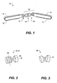
- FIG. 1 shown is an illustration of a serpentine robotic crawler according to a first exemplary embodiment of the present invention.
- the serpentine robotic crawler 10 as including a first frame 12 and a second frame 14.
- Each frame includes a continuous track 16, 18 rotatably supported by the frame.
- the frames are coupled together by a multiple degree of freedom actuated linkage arm 20.
- the multiple degree of freedom linkage arm includes a first wrist-like actuated linkage 22 coupled to the first frame, a second wrist-like actuated linkage 24 coupled to the second frame, and an elbow-like actuated joint 26 coupled between the first and second wrist-like actuated linkage.
- the wrist-like actuated linkages 22, 24, shown in further detail in FIG. 2 provide bending movement about two different lateral axes 28, 29 and rotational movement about a longitudinal axis 30.
- Longitudinal refers to a direction generally oriented along the actuated linkage, such that movement about a longitudinal axis corresponds to twisting or rotational movement.
- Lateral refers to a direction generally oriented perpendicularly or at an angle to the longitudinal axis, such that movement about a lateral axis corresponds to bending movement.
- the two different lateral axes can be, but are not limited to, being at right angles to each other.
- the elbow-like actuated joint shown in further detail in FIG. 3 , provides bending movement about a lateral axis 32.
- the wrist-like actuated linkages 22, 24 can be configured in various ways.
- the wrist-like actuated linkage can include a series coupled combination of a yaw bending joint, a pitch bending joint, and a rotational joint, with various arm linkages coupled between the joints and the frame.
- a wrist-like actuated linkage 40 can include a yaw arm 42 coupled to the frame 12,14 through a yaw bending joint 44 which provides yaw 46 bending about a lateral axis 28 orientated substantially vertically relative to the frame when the continuous track 16, 18 is in a nominal operating position and in contact with a substantially horizontal supporting surface.
- the wrist-like actuated linkage can also include a pitch arm 48 coupled to the yaw arm through a pitch bending joint 50 providing pitch 52 bending about a lateral axis 29 oriented substantially horizontally relative to the frame.
- the wrist-like actuated linkage can also include a rotary joint 54 providing roll 56 rotation about the longitudinal axis 30 of the pitch arm.
- References to vertical and horizontal refer to nominal directions relative to a substantially horizontal supporting surface on which the serpentine robotic crawler is operated and when the continuous track is in contact with the supporting surface. It will be appreciated that, when the serpentine robotic crawler is tipped over, the vertical direction relative to the serpentine robotic crawler is actually horizontal relative to the supporting surface.
- the frame can be configured in various ways so that the continuous track is substantially enclosed so that only a bottom portion 60 is exposed as illustrated in FIG. 5 , or so that the continuous track is partially enclosed so that a top portion 62 and bottom portion 60 of the continuous track 16, 18 are exposed as illustrated in FIG. 6 .
- the frame can be oriented with either side up and still provide locomotion. The benefits of this configuration will become more apparent as the operation of a serpentine robotic crawler is discussed further below.
- the frame can include a drive (not shown) coupled to the continuous track to drive the continuous track.
- the drive can be configured to drive the continuous track in either direction (e.g., clockwise and counterclockwise) over a range of speeds.
- Various types of drives and coupling techniques for applying drive power to a continuous track are known and can be applied in embodiments of the present invention.
- the combination of the high degree of freedom actuated linkage arm 20 with the dual single track frames 12, 14 makes the serpentine robotic crawler 10 capable of many different modes of movement as will now be described.
- Operating the serpentine robotic crawler can include articulating the actuated multi-degree of freedom linkage arm to establish a desired pose for the serpentine robotic crawler.
- Drive operation of the continuous tracks 16, 18 can be coordinated with articulation of the high degree of freedom actuated linkage arm to further control the pose and provide movement of the serpentine robotic crawler.
- torque and forces on the joints may be taken into account as discussed further herein.
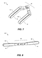
- a first pose will be referred to herein as the "tank" configuration, where the first frame 12 and second frame 14 are positioned side by side as illustrated in FIG. 7 .
- the frames extend in the same direction from the actuated linkage arm 20, and can be, but need not be, parallel.
- the tank configuration provides lateral stability to the serpentine robotic crawler 10, for example when traversing a steep slope.
- the serpentine robotic crawler can be moved in a forward and reserve direction by driving the continuous tracks 16, 18 in the same direction, and turned by driving the continuous tracks in the opposite direction. In general, moving the serpentine robotic crawler in the tank-like configuration can involve applying different drive speeds (including opposite directions) to the continuous tracks.
- a second pose is where the first frame 12 and second frame 14 are aligned end-to-end as illustrated in FIG. 8 .
- the frames can be, but need not be, parallel.
- the train configuration provides a smaller profile, allowing the serpentine robotic crawler 10 to enter small holes, pipes, tunnels, and the like.
- the train configuration also allows the serpentine robotic crawler to bridge gaps and holes.
- forward and reverse motion is provided by driving the continuous tracks 16, 18. Note that, relative to the tank configuration, the direction sense of one of the continuous tracks is reversed.
- Turning of the serpentine robotic crawler can be provided by operation of the actuated linkage arm 20 to create an angle between the first frame and second frame.
- the serpentine robotic crawler can also be configured for climbing the exterior of structure. As illustrated in FIG. 9 , the serpentine robotic crawler 10 is wrapped around the structure 70 so that exposed portions 72, 74 of the continuous tracks face toward each other and contact opposite outer surfaces 76, 78 of the structure. The continuous tracks can be driven to move the serpentine robotic crawler up and down the structure. Many different structural geometries, including for example a pole, can be climbed in this outside-climbing configuration.
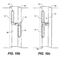
- the serpentine robotic crawler can also be configured for climbing the interior of a structure.
- FIGS. 10(a) and 10(b) illustrate two different inside-climbing configurations.
- the serpentine robotic crawler 10 is configured so that exposed portions 72, 74 of the continuous tracks face away from each other and are in contact with opposite inner surfaces 80, 82 of the structure 70.
- the inside-climbing configuration can be useful for climbing pipes, chimneys, wall interiors, and the like.
- serpentine robotic crawler may also be possible for the serpentine robotic crawler to climb the interior of a structure 70 by facing exposed portions 72, 74 of the continuous tracks in the same direction, in contact with the same inner surface 80 of the structure, and placing a portion of the actuated linkage in contact with the opposite inner surface 82, as illustrated in FIG. 10(c) .
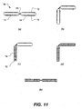
- FIGS. 11(a)-11(e) illustrate one technique self-righting of an overturned serpentine robotic crawler in overhead view.
- the serpentine robotic crawler 10 is shown lying on its side in FIG. 11(a) , with the exposed portions 72, 74 of the continuous track no longer in contact with the surface.
- the actuated linkage 20 is activated to position the frames at an approximately 90-degree angle as shown in FIG. 11(b) . This provides a stable configuration, at which point one of the wrist-like joints can be rotated to place one of exposed surfaces of a continuous track in contact with the surface as shown in FIG. 11(c) .
- the other wrist-like joint is then rotated to similarly position the other frame as shown in FIG. 11(d) .
- both continuous tracks are in contact with the surface.
- the linkage arm is then straightened so that the serpentine robotic crawler can continue on as shown in FIG. 11(e) .
- straightening the linkage arm can occur while the serpentine robotic crawler has begun moving forward.
- the serpentine robotic crawler can include systems such as track load sensors, inertial references, and the like to assist in determining and correcting its orientation. For example, commonly owned and co-pending U.S. Provisional Patent Application No.
- 60/858,805 entitled “Conformable Track Assembly for a Robotic Crawler”, filed November 13, 2006 and incorporated herein by reference, describes a suspension system for an endless track which includes a deflector and a load-sensing element which can be used in embodiments of the present invention.
- the serpentine robotic crawler 10 can be placed into an arched configuration by operating the actuated linkage arm 20 (as described further below) so the serpentine robotic crawler is substantially supported by only furthest apart ends of the tracks.
- This configuration can be unstable, allowing further actuation of the articulated linkage arm to cause the serpentine robotic crawler to tip over.
- a serpentine robotic crawler in accordance with embodiments of the present invention is capable of a large number of poses and movement modes not possible with more conventional wheeled or tracked vehicles. Additional poses the serpentine robotic crawler 10 can adopt are illustrated in FIG. 12(a)-12(f) .
- the actuated linkage 20 can position the frames 12, 14 at an angle relative to each other.
- the serpentine robotic crawler can thus be arched in an up ( FIG. 12(a) ), down ( FIG. 12(b) ), left ( FIG. 12(c) ), or right ( FIG. 12(d) ) direction. Arching up and down can help to navigate uneven portions of terrain, such as dips and bumps. Arching left and right can help in turning and avoiding obstacles.
- Another pose can be referred to as a zag configuration, where the frames are oriented in parallel lines but offset and extending in opposite directions from the actuated linkage arm, as shown in FIG. 12(e) . Similar to the tank configuration, the zag configuration can provide additional stability to the serpentine robotic crawler.
- the linkage arm includes at least seven actuated joints providing motion about seven different axes (although some of these axes may be aligned with each other at times). These joints can be uni-axial, bi-axial, or tri-axial joints.
- the linkage arm can include a series coupled combination of any of the following:
- the linkage arm can include a series combination of five actuated uni-axial bending joints and two actuated uni-axial rotary joints, wherein the bending joints provide at least two different joint axes.
- four bending joints can be symmetrically disposed about a fifth bending joint located in the center of the linkage, two bending joints on each side of the center.
- the rotary joints can also be symmetrically disposed about the center.
- the rotary joints can be located adjacent to the fifth (centered) bending joint (e.g., as illustrated in FIG. 7 ), located between the symmetrically disposed bending joints, or located adjacent to the frames.
- bi-axial joints which provide the same degrees of freedom as two uni-axial joints in series, or tri-axial joints, which provide the same degrees of freedom as three uni-axial joints in series, can also be used.
- a bi-axial joint can, for example, provide bending in two axes. These axes can, but need not be, orthogonal.
- a tri-axial joint can, for example, provide bending in two lateral axes and rotation about a third longitudinal axis.
- Joints need not be limited to revolute joints which provide bending or rotational movement. Prismatic joints which provide translational movement can also be included. Joints may incorporate both revolute and prismatic features to provide, for example, eccentric motions.
- the serpentine robotic crawler can include a control subsystem 90.
- the control subsystem is in communication with each of the actuated joints 92 of the linkage arm 20 to control the pose of the serpentine robotic crawler.
- the control system can also be in communication with the drive units 94, which are coupled to the first and second continuous track, to control the speed and direction of continuous track rotation to control movement of the serpentine robotic crawler.
- the control system can also include a communication network 96 configured to exchange communication between the control subsystem, the joints in the linkage arm, and the drive units.
- the communications network can include wireless components.
- the communication network can include a wireless portion providing communication between the serpentine robotic crawler and a control system located remotely from the serpentine robotic crawler.
- the control system can use a master replica for control of the serpentine robotic crawler.
- a master replica is located remotely from the serpentine robotic crawler.
- the master replica contains the same joints as the serpentine robotic crawler, and is manually manipulated into the desired poses.
- Sensors located at the joints sense the position of the joints, and these positions are communicated to the serpentine robotic crawler which actuates its joints to attempt to establish the same pose.
- the joints in the serpentine robotic crawler can include force sensors, torque sensors, or both, allowing the force and/or torque on the joints to be measured.
- the joint forces and/or torques can optionally be communicated back to the replica master, providing force feedback into the control system.
- Various force feedback control systems are known which can be applied to embodiments of the present invention.
- the control system may be integrated into the serpentine robotic crawler thereby allowing the crawler to operate autonomously.
- the crawler may operate autonomously for an extended period of time.
- the control system can include distributed joint and track controllers which locally control one or more closely associated joints. Distributed joint and track controllers can communicate with a master controller located within the crawler or located externally from the crawler.
- control of the serpentine robotic crawler can include control of a first frame, with other frames slaved to the first frame.
- an operator can control the orientation and movement of the first frame.
- the other frames then follow the first frame.
- One particular control scheme can include automatically steering the other frames in following the first frame so as to minimize forces imposed on the actuated linkage arm.
- control of the serpentine robotic crawler can include use of a joystick.
- a two-dimensional joystick can be used to control a pose of the robot, for example by controlling motion of the actuated linkage via the joystick. Movement of the two-degrees of motion in the joystick can be translated into complex movements of the multi-degree of freedom actuated linkage via predefined primitives.
- movement of the joystick to the left or right can arch the serpentine robotic crawler to the left or right, with sustained holding of the joystick moving the serpentine robotic crawler between a tank-like configuration and a snake-like configuration.
- movement of the joystick to the front or back can arch the serpentine robotic crawler up or down, with sustained holding of the joystick forward or backward placing the serpentine robotic crawler into an inside- or outside-climbing configuration.
- a variety of mappings from a joystick to movements can be defined, as will be appreciated.
- Interface between an operator and the control system can be provided via a menu driven interface operational on a personal computer, laptop, personal data assistant, and the like, as is known.
- the control system can also be configured to provide a degree of compliance in the joints.
- forces applied to the joints by the environment of the flexible robotic crawler can be sensed and communicated to the control system.
- the joints can be allowed to move.
- joints can include breakaway clutches, implemented either via mechanical systems, electronic systems, or hybrid electro-mechanical systems.
- Force limit thresholds can be made adjustable to provide variable compliance to the serpentine robotic crawler. For example, high thresholds to provide a stiff posture may prove useful in pushing through certain types of obstructions. Alternately, low thresholds may prove useful in bending around other types of obstructions.
- control system can be implemented using a processing system.
- Various movement primitives can be preprogrammed, including for example primitives to assume certain poses (e.g., tank, zag, arched, train, or climbing configurations), and primitives for movement (e.g., forward, backwards).
- Control can include feedback from joint force sensors and environmental sensors.
- Hybrid human and automated control can be combined.
- high-level manual commands/primitives can be implemented using automated low-level feedback loops that execute the commands/primitives.
- Control function can be divided into subsystems, including for example, pose control, compliance control, movement control, force control, and hybrid combinations thereof.
- the serpentine robotic crawler 100 includes a plurality of frame units 102, each having a continuous track rotatably supported therein.
- the continuous track can have one or more exposed surfaces, as discussed above.
- At least one actuated multi-degree of freedom linkage arm 104 is coupled between the frame units.
- N frame units N-1 linkage arms are used to intercouple the frames into a multi-frame train.
- the actuated multi-degree of freedom linkage arm includes at least seven joint axes, for example as described above.
- the actuated multi-degree of freedom linkage arm can be removably connected between the frame units, to allow the multi-frame train to be reconfigured, for example into a number of individual frames, pairs of frames, or shorter multi-frame trains.
- a serpentine robotic crawler can also include various sensors or tools positioned on the actuated multi-degree of freedom linkage arm and or the frame.
- a serpentine robotic crawler 110 can have cameras 116 disposed on one 112 of the frames.
- cameras can be disposed on both the leading and the trailing frame.
- a front camera can be used primarily for scanning the environment, and a rear camera can be used for observing the pose of the serpentine robotic crawler for control purposes.
- Other sensors including for example, radar, lidar, infrared detectors, temperature sensors, chemical sensors, force sensors, motion detectors, microphones, antennas, and the like can be disposed on the serpentine robotic crawler.
- serpentine robotic crawler can include articulated arms disposed on the frame.
- Commonly owned and co-pending U.S. Provisional Patent Application No. 60/858,915 entitled “Tracked Robotic Vehicle with Articulated Arms,” filed November 13, 2006, describes a serpentine robotic crawler having articulated arms, and is herein incorporated by reference.
- serpentine robotic crawlers in accordance with embodiments of the present invention can be deployed in a variety of applications and environments.
- applications can include search and rescue, military operations, and industrial operations.
- the serpentine robotic crawler can help to avoid the need to expose humans to hazardous environments, such as unstable buildings, military conflict situations, and chemically, biologically, or nuclear contaminated environments.
- the configurational flexibility of the serpentine robotic crawler provides multiple movement modes. For example, movement in a tank-like configuration can provide high stability. Movement in a snake-like configuration can provide access through narrow passages or pipes. Climbing the outside of structures, e.g., a pole, and climbing the inside of structures, e.g., inside a pipe, are also possible.
Landscapes
- Engineering & Computer Science (AREA)
- Chemical & Material Sciences (AREA)
- Combustion & Propulsion (AREA)
- Mechanical Engineering (AREA)
- Transportation (AREA)
- General Engineering & Computer Science (AREA)
- Manipulator (AREA)
- Toys (AREA)
- Braiding, Manufacturing Of Bobbin-Net Or Lace, And Manufacturing Of Nets By Knotting (AREA)
Description
- The present invention relates to small, unmanned ground robotic vehicles. More particularly, the present invention relates to a serpentine robotic crawler having multiple tracked frame units interconnected through a high-degree of freedom actuated linkage.
- Robotics is an active area of research, and many different types of robotic vehicles have been developed for various tasks. For example, unmanned aerial vehicles have been quite successful in military aerial reconnaissance. Less success has been achieved with unmanned ground vehicles, however, in part because the ground environment is significantly more difficult to traverse than the airborne environment.
- Unmanned ground vehicles face many challenges when attempting mobility. Terrain can vary widely, including for example, loose and shifting materials, obstacles, vegetation, limited width or height openings, steps, and the like. A vehicle optimized for operation in one environment may perform poorly in other environments.
- There are also tradeoffs associated with the size of vehicle. Large vehicles can handle some obstacles better, including for example steps, drops, gaps, and the like. On the other hand, large vehicles cannot easily negotiate narrow passages or crawl inside pipes, and are more easily deterred by vegetation. Large vehicles also tend to be more readily spotted, and thus are less desirable for discrete surveillance applications. In contrast, while small vehicles are more discrete, surmounting obstacles becomes a greater navigational challenge.
- A variety of mobility configurations have been adapted to traverse difficult terrain. These options include legs, wheels, and tracks. Legged robots can be agile, but use complex control mechanisms to move and achieve stability. Wheeled vehicles can provide high mobility, but provide limited traction and require width in order to achieve stability.
- Tracked vehicles are know and have traditionally been configured in a tank-like configuration. While tracked vehicles can provide a high degree of stability in some environments, tracked vehicles typically provide limited maneuvrability with very small vehicles. Furthermore, known tracked vehicles are unable to accommodate a wide variety of obstacles, particularly when the terrain is narrow and the paths are tortuous and winding.
- Further examples of prior art arrangements are disclosed in
DE 197 14464 A1 ,FR 2638813 A US 7188568 B2 . - The present invention includes a serpentine robotic crawler as defined in
claim 1 which helps to overcome problems and deficiencies inherent in the prior art. In one embodiment, the serpentine robotic crawler includes a first frame and a second frame, each frame having a continuous track rotatably supported therein. The first and second frame are coupled by an actuated linkage arm. The linkage arm has a pair of wrist-like actuated linkage at each end, coupled to respective frames, and an elbow-like actuated joint between the wrist-like actuated linkages. Additional features of the invention are disclosed in the dependent claims. - The present invention will become more fully apparent from the following description and appended claims, taken in conjunction with the accompanying drawings. Understanding that these drawings merely depict exemplary embodiments of the present invention they are, therefore, not to be considered limiting of its scope. It will be readily appreciated that the components of the present invention, as generally described and illustrated in the figures herein, can be arranged and designed in a wide variety of different configurations. Nonetheless, the invention will be described and explained with additional specificity and detail through the use of the accompanying drawings in which:
-
FIG. 1 illustrates a perspective view of a serpentine robotic cra wler according to a an exemplary embodiment of the present invention; -
FIG. 2 illustrates a perspective view of a wrist-like actuated linkage in accordance with an embodiment of the present invention; -
FIG. 3 Illustrates a perspective view of an elbow-like actuated linkage in accordance with an embodiment of the present invention; -
FIG. 4 illustrates a perspective view of a wrist-like actuated linkage in accordance with an embodiment of the present invention; -
FIG. 5 illustrates a perspective view of a frame having a substantially enclosed continuous track with an exposed bottom portion in accordance with an embodiment of the present invention; -
FIG. 6 illustrates a perspective view of a frame having a continuous track with an exposed top portion and an exposed bottom portion in accordance with an embodiment of the present invention; -
FIG. 7 illustrates a perspective view of a serpentine robotic crawler in a tank-like configuration in accordance with an embodiment of the present invention; -
FIG. 8 illustrates a perspective view of a serpentine robotic crawler in a snake-like configuration in accordance with an embodiment of the present invention; -
FIG. 9 illustrates a perspective view of a serpentine robotic crawler in an outside-climbing configuration in accordance with an embodiment of the present invention; -
FIGS. 10(a) - 10(c ) illustrate perspective views of a serpentine robotic crawler in different inside-climbing configurations in accordance with an embodiment of the present invention; -
FIGS. 11(a) - 11(e) illustrate a top view of a sequence of movements of a serpentine robotic crawler righting itself in accordance with an embodiment of the present invention; -
FIGS. 12(a) - 12(f) illustrate perspective views of various poses for a serpentine robotic crawler in accordance with an embodiment of the present invention; -
FIG. 13 illustrates a schematic diagram of a control system in accordance with an embodiment of the present invention; -
FIG. 14 illustrates a serpentine robotic crawler in accordance with an alternate embodiment of the present invention; and -
FIG. 15 illustrates a serpentine robotic crawler in accordance with yet another alternate embodiment of the present invention. - The following detailed description of exemplary embodiments of the invention makes reference to the accompanying drawings, which form a part hereof and in which are shown, by way of illustration, exemplary embodiments in which the invention may be practiced. While these exemplary embodiments are described in sufficient detail to enable those skilled in the art practice the invention, it should be understood that other embodiments may be realized and that various changes to the invention may be made without departing from the spirit and scope of the present invention. Thus, the following more detailed description of the embodiments of the present invention is not intended to limit the scope of the invention, as claimed, but is presented for purposes of illustration only and not limitation to describe the features and characteristics of the present invention, to set forth the best mode of operation of the invention, and to sufficiently enable one skilled in the art to practice the invention. Accordingly, the scope of the present invention is to be defined solely by the appended claims.
- The following detailed description and exemplary embodiments of the invention will be best understood by reference to the accompanying drawings, wherein the elements and features of the invention are designated by numerals throughout.
- With reference to
FIG. 1 , shown is an illustration of a serpentine robotic crawler according to a first exemplary embodiment of the present invention. Specifically,FIG. 1 illustrates the serpentinerobotic crawler 10 as including afirst frame 12 and asecond frame 14. Each frame includes acontinuous track linkage arm 20. The multiple degree of freedom linkage arm includes a first wrist-like actuatedlinkage 22 coupled to the first frame, a second wrist-like actuatedlinkage 24 coupled to the second frame, and an elbow-like actuatedjoint 26 coupled between the first and second wrist-like actuated linkage. - The wrist-like actuated
linkages FIG. 2 , provide bending movement about two differentlateral axes longitudinal axis 30. Longitudinal refers to a direction generally oriented along the actuated linkage, such that movement about a longitudinal axis corresponds to twisting or rotational movement. Lateral refers to a direction generally oriented perpendicularly or at an angle to the longitudinal axis, such that movement about a lateral axis corresponds to bending movement. The two different lateral axes can be, but are not limited to, being at right angles to each other. The elbow-like actuated joint, shown in further detail inFIG. 3 , provides bending movement about alateral axis 32. - The wrist-like actuated
linkages FIG. 4 , in accordance with an embodiment of the present invention, a wrist-like actuatedlinkage 40 can include ayaw arm 42 coupled to theframe lateral axis 28 orientated substantially vertically relative to the frame when thecontinuous track pitch arm 48 coupled to the yaw arm through a pitch bending joint 50 providingpitch 52 bending about alateral axis 29 oriented substantially horizontally relative to the frame. The wrist-like actuated linkage can also include a rotary joint 54 providingroll 56 rotation about thelongitudinal axis 30 of the pitch arm. References to vertical and horizontal refer to nominal directions relative to a substantially horizontal supporting surface on which the serpentine robotic crawler is operated and when the continuous track is in contact with the supporting surface. It will be appreciated that, when the serpentine robotic crawler is tipped over, the vertical direction relative to the serpentine robotic crawler is actually horizontal relative to the supporting surface. - Considering the
frames continuous tracks bottom portion 60 is exposed as illustrated inFIG. 5 , or so that the continuous track is partially enclosed so that atop portion 62 andbottom portion 60 of thecontinuous track FIG. 6 . Note that, where both the top and bottom portion of the continuous track is exposed, the frame can be oriented with either side up and still provide locomotion. The benefits of this configuration will become more apparent as the operation of a serpentine robotic crawler is discussed further below. The frame can include a drive (not shown) coupled to the continuous track to drive the continuous track. Optionally, the drive can be configured to drive the continuous track in either direction (e.g., clockwise and counterclockwise) over a range of speeds. Various types of drives and coupling techniques for applying drive power to a continuous track are known and can be applied in embodiments of the present invention. - Referring back to
FIG. 1 , the combination of the high degree of freedom actuatedlinkage arm 20 with the dual single track frames 12, 14 makes the serpentinerobotic crawler 10 capable of many different modes of movement as will now be described. Operating the serpentine robotic crawler can include articulating the actuated multi-degree of freedom linkage arm to establish a desired pose for the serpentine robotic crawler. Drive operation of thecontinuous tracks - A first pose will be referred to herein as the "tank" configuration, where the
first frame 12 andsecond frame 14 are positioned side by side as illustrated inFIG. 7 . The frames extend in the same direction from the actuatedlinkage arm 20, and can be, but need not be, parallel. The tank configuration provides lateral stability to the serpentinerobotic crawler 10, for example when traversing a steep slope. The serpentine robotic crawler can be moved in a forward and reserve direction by driving thecontinuous tracks - A second pose, referred to herein as the "train" configuration, is where the
first frame 12 andsecond frame 14 are aligned end-to-end as illustrated inFIG. 8 . The frames can be, but need not be, parallel. The train configuration provides a smaller profile, allowing the serpentinerobotic crawler 10 to enter small holes, pipes, tunnels, and the like. The train configuration also allows the serpentine robotic crawler to bridge gaps and holes. In the train configuration, forward and reverse motion is provided by driving thecontinuous tracks linkage arm 20 to create an angle between the first frame and second frame. - The serpentine robotic crawler can also be configured for climbing the exterior of structure. As illustrated in
FIG. 9 , the serpentinerobotic crawler 10 is wrapped around thestructure 70 so that exposedportions outer surfaces 76, 78 of the structure. The continuous tracks can be driven to move the serpentine robotic crawler up and down the structure. Many different structural geometries, including for example a pole, can be climbed in this outside-climbing configuration. - The serpentine robotic crawler can also be configured for climbing the interior of a structure.
FIGS. 10(a) and10(b) illustrate two different inside-climbing configurations. In an inside-climbing configuration, the serpentinerobotic crawler 10 is configured so that exposedportions inner surfaces structure 70. The inside-climbing configuration can be useful for climbing pipes, chimneys, wall interiors, and the like. - It may also be possible for the serpentine robotic crawler to climb the interior of a
structure 70 by facing exposedportions inner surface 80 of the structure, and placing a portion of the actuated linkage in contact with the oppositeinner surface 82, as illustrated inFIG. 10(c) . - Various articulated movements are also possible for the serpentine robotic crawler. For example,
FIGS. 11(a)-11(e) , illustrate one technique self-righting of an overturned serpentine robotic crawler in overhead view. The serpentinerobotic crawler 10 is shown lying on its side inFIG. 11(a) , with the exposedportions linkage 20 is activated to position the frames at an approximately 90-degree angle as shown inFIG. 11(b) . This provides a stable configuration, at which point one of the wrist-like joints can be rotated to place one of exposed surfaces of a continuous track in contact with the surface as shown inFIG. 11(c) . The other wrist-like joint is then rotated to similarly position the other frame as shown inFIG. 11(d) . As this point, both continuous tracks are in contact with the surface. The linkage arm is then straightened so that the serpentine robotic crawler can continue on as shown inFIG. 11(e) . Optionally, straightening the linkage arm can occur while the serpentine robotic crawler has begun moving forward. The serpentine robotic crawler can include systems such as track load sensors, inertial references, and the like to assist in determining and correcting its orientation. For example, commonly owned and co-pendingU.S. Provisional Patent Application No. 60/858,805 - Other self-righting movement modes are also possible. For example, the serpentine
robotic crawler 10 can be placed into an arched configuration by operating the actuated linkage arm 20 (as described further below) so the serpentine robotic crawler is substantially supported by only furthest apart ends of the tracks. This configuration can be unstable, allowing further actuation of the articulated linkage arm to cause the serpentine robotic crawler to tip over. - A serpentine robotic crawler in accordance with embodiments of the present invention is capable of a large number of poses and movement modes not possible with more conventional wheeled or tracked vehicles. Additional poses the serpentine
robotic crawler 10 can adopt are illustrated inFIG. 12(a)-12(f) . For example, the actuatedlinkage 20 can position theframes FIG. 12(a) ), down (FIG. 12(b) ), left (FIG. 12(c) ), or right (FIG. 12(d) ) direction. Arching up and down can help to navigate uneven portions of terrain, such as dips and bumps. Arching left and right can help in turning and avoiding obstacles. - Another pose can be referred to as a zag configuration, where the frames are oriented in parallel lines but offset and extending in opposite directions from the actuated linkage arm, as shown in
FIG. 12(e) . Similar to the tank configuration, the zag configuration can provide additional stability to the serpentine robotic crawler. - While the various poses have been described in a static sense, it will be understood that the serpentine robotic crawler can dynamically vary its pose as it is operated. Moreover, modified versions of the above poses may also prove useful, depending on the environment in which the serpentine robotic crawler operates.
- As discussed above, various dynamic movement modes are possible. While the foregoing discussion has principle focused on operation of the endless tracks to provide propulsion, it will be appreciated that operation of the actuated linkage can also assist in propulsion. For example, sudden jerky movements of the actuated linkage can help to provide traction or to free the serpentine robotic crawler when entangled. As another example, the spatial orientation of the tracks can be periodically or continuously adjusted by the actuated linkage to conform to a surface being traveled over. For example,
FIG. 12(f) illustrates a twisted configuration. - Returning to the discussion of the articulated multi-degree of
freedom linkage arm 20, various other configurations are also possible for embodiments of a serpentine robotic crawler. In general, the linkage arm includes at least seven actuated joints providing motion about seven different axes (although some of these axes may be aligned with each other at times). These joints can be uni-axial, bi-axial, or tri-axial joints. The linkage arm can include a series coupled combination of any of the following: - 7 uni-axial joints
- 3 three uni-axial joints and 2 bi-axial joints
- 1 uni-axial joint and 2 tri-axial joints
- 2 bi-axial joints and 1 tri-axial joint
- For example, the linkage arm can include a series combination of five actuated uni-axial bending joints and two actuated uni-axial rotary joints, wherein the bending joints provide at least two different joint axes. For example, four bending joints can be symmetrically disposed about a fifth bending joint located in the center of the linkage, two bending joints on each side of the center. The rotary joints can also be symmetrically disposed about the center. For example, the rotary joints can be located adjacent to the fifth (centered) bending joint (e.g., as illustrated in
FIG. 7 ), located between the symmetrically disposed bending joints, or located adjacent to the frames. - Alternately, bi-axial joints, which provide the same degrees of freedom as two uni-axial joints in series, or tri-axial joints, which provide the same degrees of freedom as three uni-axial joints in series, can also be used. A bi-axial joint can, for example, provide bending in two axes. These axes can, but need not be, orthogonal. A tri-axial joint can, for example, provide bending in two lateral axes and rotation about a third longitudinal axis.
- Joints need not be limited to revolute joints which provide bending or rotational movement. Prismatic joints which provide translational movement can also be included. Joints may incorporate both revolute and prismatic features to provide, for example, eccentric motions.
- Control of the serpentine
robotic vehicle 10 will now be discussed in further detail. As noted above, movement and pose of the serpentine robotic vehicle can be controlled through articulation of the actuated multiple degree offreedom linkage arm 20 and rotation of thecontinuous tracks FIG. 13 , the serpentine robotic crawler can include acontrol subsystem 90. The control subsystem is in communication with each of the actuatedjoints 92 of thelinkage arm 20 to control the pose of the serpentine robotic crawler. The control system can also be in communication with thedrive units 94, which are coupled to the first and second continuous track, to control the speed and direction of continuous track rotation to control movement of the serpentine robotic crawler. The control system can also include acommunication network 96 configured to exchange communication between the control subsystem, the joints in the linkage arm, and the drive units. - Various implementations of the communications network are possible. For example, various communications protocols are known which allow a large number of nodes to communicate on a limited number of wires, including for example RS-485, RHAMIS, USB, Ethernet, and the like. Alternately, the communications network can include wireless components. For example, the communication network can include a wireless portion providing communication between the serpentine robotic crawler and a control system located remotely from the serpentine robotic crawler.
- Various implementations of the control subsystem are possible. For example, in one embodiment, the control system can use a master replica for control of the serpentine robotic crawler. In a master replica control system, a master replica is located remotely from the serpentine robotic crawler. The master replica contains the same joints as the serpentine robotic crawler, and is manually manipulated into the desired poses. Sensors located at the joints sense the position of the joints, and these positions are communicated to the serpentine robotic crawler which actuates its joints to attempt to establish the same pose. Optionally, the joints in the serpentine robotic crawler can include force sensors, torque sensors, or both, allowing the force and/or torque on the joints to be measured. The joint forces and/or torques can optionally be communicated back to the replica master, providing force feedback into the control system. Various force feedback control systems are known which can be applied to embodiments of the present invention.
- The control system may be integrated into the serpentine robotic crawler thereby allowing the crawler to operate autonomously. For example, the crawler may operate autonomously for an extended period of time. In an embodiment, the control system can include distributed joint and track controllers which locally control one or more closely associated joints. Distributed joint and track controllers can communicate with a master controller located within the crawler or located externally from the crawler.
- In another embodiment, control of the serpentine robotic crawler can include control of a first frame, with other frames slaved to the first frame. For example, an operator can control the orientation and movement of the first frame. The other frames then follow the first frame. One particular control scheme can include automatically steering the other frames in following the first frame so as to minimize forces imposed on the actuated linkage arm.
- As another example, control of the serpentine robotic crawler can include use of a joystick. For example, a two-dimensional joystick can be used to control a pose of the robot, for example by controlling motion of the actuated linkage via the joystick. Movement of the two-degrees of motion in the joystick can be translated into complex movements of the multi-degree of freedom actuated linkage via predefined primitives. As a particular example, movement of the joystick to the left or right can arch the serpentine robotic crawler to the left or right, with sustained holding of the joystick moving the serpentine robotic crawler between a tank-like configuration and a snake-like configuration. As another particular example, movement of the joystick to the front or back can arch the serpentine robotic crawler up or down, with sustained holding of the joystick forward or backward placing the serpentine robotic crawler into an inside- or outside-climbing configuration. Of course, a variety of mappings from a joystick to movements can be defined, as will be appreciated. Interface between an operator and the control system can be provided via a menu driven interface operational on a personal computer, laptop, personal data assistant, and the like, as is known.
- The control system can also be configured to provide a degree of compliance in the joints. For example, forces applied to the joints by the environment of the flexible robotic crawler can be sensed and communicated to the control system. When certain force thresholds are exceeded, the joints can be allowed to move. For example, joints can include breakaway clutches, implemented either via mechanical systems, electronic systems, or hybrid electro-mechanical systems. Force limit thresholds can be made adjustable to provide variable compliance to the serpentine robotic crawler. For example, high thresholds to provide a stiff posture may prove useful in pushing through certain types of obstructions. Alternately, low thresholds may prove useful in bending around other types of obstructions.
- As another example, the control system can be implemented using a processing system. Various movement primitives can be preprogrammed, including for example primitives to assume certain poses (e.g., tank, zag, arched, train, or climbing configurations), and primitives for movement (e.g., forward, backwards). Control can include feedback from joint force sensors and environmental sensors. Hybrid human and automated control can be combined. For example, high-level manual commands/primitives can be implemented using automated low-level feedback loops that execute the commands/primitives. Control function can be divided into subsystems, including for example, pose control, compliance control, movement control, force control, and hybrid combinations thereof.
- An alternate configuration of a serpentine robotic crawler is illustrated in
FIG. 14 in accordance with an embodiment of the present invention. The serpentinerobotic crawler 100 includes a plurality offrame units 102, each having a continuous track rotatably supported therein. For example, the continuous track can have one or more exposed surfaces, as discussed above. At least one actuated multi-degree offreedom linkage arm 104 is coupled between the frame units. For example, with N frame units, N-1 linkage arms are used to intercouple the frames into a multi-frame train. The actuated multi-degree of freedom linkage arm includes at least seven joint axes, for example as described above. Optionally, the actuated multi-degree of freedom linkage arm can be removably connected between the frame units, to allow the multi-frame train to be reconfigured, for example into a number of individual frames, pairs of frames, or shorter multi-frame trains. - A serpentine robotic crawler can also include various sensors or tools positioned on the actuated multi-degree of freedom linkage arm and or the frame. For example, as illustrated in
FIG. 15 , a serpentinerobotic crawler 110 can havecameras 116 disposed on one 112 of the frames. As another example, cameras can be disposed on both the leading and the trailing frame. For example, a front camera can be used primarily for scanning the environment, and a rear camera can be used for observing the pose of the serpentine robotic crawler for control purposes. Other sensors, including for example, radar, lidar, infrared detectors, temperature sensors, chemical sensors, force sensors, motion detectors, microphones, antennas, and the like can be disposed on the serpentine robotic crawler. As another example, tools, including for example, light sources, clamps, grippers, manipulators, cutters, drills, material samplers, and the like can also be disposed on the serpentine robotic crawler. As another example, the serpentine robotic crawler can include articulated arms disposed on the frame. Commonly owned and co-pendingU.S. Provisional Patent Application No. 60/858,915 - Summarizing and reiterating to some extent, serpentine robotic crawlers in accordance with embodiments of the present invention can be deployed in a variety of applications and environments. For example, and not by way of limitation, applications can include search and rescue, military operations, and industrial operations. The serpentine robotic crawler can help to avoid the need to expose humans to hazardous environments, such as unstable buildings, military conflict situations, and chemically, biologically, or nuclear contaminated environments. The configurational flexibility of the serpentine robotic crawler provides multiple movement modes. For example, movement in a tank-like configuration can provide high stability. Movement in a snake-like configuration can provide access through narrow passages or pipes. Climbing the outside of structures, e.g., a pole, and climbing the inside of structures, e.g., inside a pipe, are also possible.
- The foregoing detailed description describes the invention with reference to specific exemplary embodiments. However, it will be appreciated that various modifications and changes can be made without departing from the scope of the present invention as set forth in the appended claims. The detailed description and accompanying drawings are to be regarded as merely illustrative, rather than as restrictive, and all such modifications or changes, if any, are intended to fall within the scope of the present invention as described and set forth herein.
Claims (7)
- A serpentine robotic crawler (10) comprising:a first frame (12) having a first continuous track (16) rotatably supported by the first frame;a first wrist-like actuated linkage (22) coupled to the first frame (12) wherein the first wrist-like actuated linkage (22) provides rotational movement about a longitudinal axis and bending movement about two different lateral axes;an elbow-like actuated joint (26) coupled to the first wrist-like actuated linkage (22) wherein the elbow-like actuated joint (26) provides bending movement about a lateral axis;a second wrist-like actuated linkage (24) coupled to the elbow-like actuated joint (26) wherein the second wrist-like actuated linkage (24) provides rotational movement about a longitudinal axis and bending movement about two different lateral axes; anda second frame (14) coupled to the second wrist-like actuated linkage (24) and having a second continuous track (18) rotatably supported by the second frame (14).
- The serpentine robotic crawler (10) of claim 1, wherein the wrist-like actuated linkage comprises:a first yaw arm coupled to the first frame through a first yaw bending joint providing yaw bending about a lateral axis oriented substantially vertically relative to a nominal operating position of the first frame;a first pitch arm coupled to the yaw arm through a first pitch bending joint providing pitch bending about a lateral axis oriented substantially horizontally relative to the nominal operating position of the first frame; anda first rotational joint coupled to the first pitch arm.
- The serpentine robotic crawler (10) of claim 1, wherein the wrist-like actuated linkage comprises:a first bending joint providing yaw bending about a substantially vertical axis relative to a nominal operating position of the first continuous track (16);a second bending joint providing pitch bending about a first substantially horizontal axis relative to the nominal operating position of the first continuous track (16); anda rotational joint providing roll rotation about a second axis, the second axis substantially orthogonal to the first substantially horizontal axis.
- The serpentine robotic crawler (10) of claim 1, further comprising a control subsystem in communication with each of the first and second wrist-like actuated linkages and the elbow-like actuated joint (26) and configured to control the pose of serpentine robotic crawler (10).
- The serpentine robotic crawler (10) of claim 4, further comprising a communication network configured to exchange communication between the control subsystem and each of the first and second wrist-like actuated linkages (22, 24) and the elbow-like actuated joint (26).
- The serpentine robotic crawler (10) of claim 4 wherein the control subsystem is also in communication with a first drive and a second drive respectively coupled to the first continuous track (16) and second continuous track (18).
- The serpentine robotic crawler (10) of claim 4 wherein the control subsystem is further configured to control compliance of the first and second wrist-like actuated linkages (22, 24) and the elbow-like actuated joint (26).
Priority Applications (1)
| Application Number | Priority Date | Filing Date | Title |
|---|---|---|---|
| EP12183386.7A EP2549165B1 (en) | 2006-11-13 | 2007-11-13 | Serpentine robotic crawler |
Applications Claiming Priority (2)
| Application Number | Priority Date | Filing Date | Title |
|---|---|---|---|
| US85891706P | 2006-11-13 | 2006-11-13 | |
| PCT/US2007/023909 WO2008076194A2 (en) | 2006-11-13 | 2007-11-13 | Serpentine robotic crawler |
Related Child Applications (2)
| Application Number | Title | Priority Date | Filing Date |
|---|---|---|---|
| EP12183386.7A Division EP2549165B1 (en) | 2006-11-13 | 2007-11-13 | Serpentine robotic crawler |
| EP12183386.7 Division-Into | 2012-09-06 |
Publications (2)
| Publication Number | Publication Date |
|---|---|
| EP2082159A2 EP2082159A2 (en) | 2009-07-29 |
| EP2082159B1 true EP2082159B1 (en) | 2013-04-10 |
Family
ID=39533470
Family Applications (2)
| Application Number | Title | Priority Date | Filing Date |
|---|---|---|---|
| EP07870883.1A Active EP2082159B1 (en) | 2006-11-13 | 2007-11-13 | Serpentine robotic crawler |
| EP12183386.7A Active EP2549165B1 (en) | 2006-11-13 | 2007-11-13 | Serpentine robotic crawler |
Family Applications After (1)
| Application Number | Title | Priority Date | Filing Date |
|---|---|---|---|
| EP12183386.7A Active EP2549165B1 (en) | 2006-11-13 | 2007-11-13 | Serpentine robotic crawler |
Country Status (6)
| Country | Link |
|---|---|
| US (1) | US7845440B2 (en) |
| EP (2) | EP2082159B1 (en) |
| JP (1) | JP5520048B2 (en) |
| CN (2) | CN101583820B (en) |
| IL (2) | IL198710A0 (en) |
| WO (1) | WO2008076194A2 (en) |
Cited By (2)
| Publication number | Priority date | Publication date | Assignee | Title |
|---|---|---|---|---|
| US9409292B2 (en) | 2013-09-13 | 2016-08-09 | Sarcos Lc | Serpentine robotic crawler for performing dexterous operations |
| US9566711B2 (en) | 2014-03-04 | 2017-02-14 | Sarcos Lc | Coordinated robotic control |
Families Citing this family (86)
| Publication number | Priority date | Publication date | Assignee | Title |
|---|---|---|---|---|
| US7960935B2 (en) | 2003-07-08 | 2011-06-14 | The Board Of Regents Of The University Of Nebraska | Robotic devices with agent delivery components and related methods |
| US8974440B2 (en) | 2007-08-15 | 2015-03-10 | Board Of Regents Of The University Of Nebraska | Modular and cooperative medical devices and related systems and methods |
| US9579088B2 (en) | 2007-02-20 | 2017-02-28 | Board Of Regents Of The University Of Nebraska | Methods, systems, and devices for surgical visualization and device manipulation |
| US8679096B2 (en) | 2007-06-21 | 2014-03-25 | Board Of Regents Of The University Of Nebraska | Multifunctional operational component for robotic devices |
| EP2397101B1 (en) | 2006-06-22 | 2018-06-13 | Board of Regents of the University of Nebraska | Magnetically coupleable robotic devices |
| US8509972B2 (en) * | 2006-08-29 | 2013-08-13 | Industrial Technology Research Institute | Electronic pet and pet interaction system thereof |
| EP2082159B1 (en) * | 2006-11-13 | 2013-04-10 | Raytheon Company | Serpentine robotic crawler |
| DE602007007807D1 (en) * | 2006-11-13 | 2010-08-26 | Raytheon Sarcos Llc | VERSATILE USEFUL BAND FOR LIGHTWEIGHT MOBILE ROBOTS |
| EP2476604B1 (en) | 2006-11-13 | 2013-08-21 | Raytheon Company | Tracked robotic crawler having a moveable arm |
| ATE504486T1 (en) | 2006-11-13 | 2011-04-15 | Raytheon Co | ADJUSTABLE TRACK ARRANGEMENT FOR A TRACKER ROBOT |
| EP2144659A1 (en) | 2007-05-07 | 2010-01-20 | Raytheon Sarcos, LLC | Method for manufacturing a complex structure |
| JP5331102B2 (en) * | 2007-05-08 | 2013-10-30 | レイセオン カンパニー | Variable primitive mapping for robotic crawlers |
| JP5285701B2 (en) * | 2007-07-10 | 2013-09-11 | レイセオン カンパニー | Modular robot crawler |
| JP5591696B2 (en) | 2007-07-12 | 2014-09-17 | ボード オブ リージェンツ オブ ザ ユニバーシティ オブ ネブラスカ | Biopsy elements, arm devices, and medical devices |
| JP2010536435A (en) | 2007-08-15 | 2010-12-02 | ボード オブ リージェンツ オブ ザ ユニバーシティ オブ ネブラスカ | Medical inflation, attachment and delivery devices and associated methods |
| US8392036B2 (en) | 2009-01-08 | 2013-03-05 | Raytheon Company | Point and go navigation system and method |
| JP5536102B2 (en) * | 2009-02-03 | 2014-07-02 | ポルマン、エックハルト | Conveyor device, conveyor chain, and chain link |
| EP2440448B1 (en) | 2009-06-11 | 2015-09-30 | Sarcos LC | Amphibious robotic crawler |
| WO2010144813A1 (en) * | 2009-06-11 | 2010-12-16 | Raytheon Sarcos, Llc | Method and system for deploying a surveillance network |
| CN101695835B (en) * | 2009-10-29 | 2012-05-09 | 哈尔滨工程大学 | Intelligent turn-over type climbing robot |
| US8894633B2 (en) | 2009-12-17 | 2014-11-25 | Board Of Regents Of The University Of Nebraska | Modular and cooperative medical devices and related systems and methods |
| WO2011080590A2 (en) * | 2009-12-30 | 2011-07-07 | Sewervue Technology Corp. | Apparatus and method for inspection of underground sewer pipes |
| JP5398589B2 (en) * | 2010-03-01 | 2014-01-29 | 本田技研工業株式会社 | Target motion evaluation device for legged mobile robot |
| US8428780B2 (en) * | 2010-03-01 | 2013-04-23 | Honda Motor Co., Ltd. | External force target generating device of legged mobile robot |
| JP5398592B2 (en) * | 2010-03-01 | 2014-01-29 | 本田技研工業株式会社 | Motion evaluation system for legged mobile robots |
| US8396593B2 (en) * | 2010-03-01 | 2013-03-12 | Honda Motor Co., Ltd. | Gait generating device of legged mobile robot |
| US8100205B2 (en) * | 2010-04-06 | 2012-01-24 | Robotex Inc. | Robotic system and method of use |
| JP2014529414A (en) | 2010-08-06 | 2014-11-13 | ボード オブ リージェンツ オブ ザ ユニバーシティ オブ ネブラスカ | Method and system for handling or delivery of natural orifice surgical material |
| US8851211B2 (en) | 2010-09-30 | 2014-10-07 | Keith L. Schlee | Multi-unit mobile robot |
| US8662213B2 (en) | 2011-01-10 | 2014-03-04 | The United States Of America As Represented By The Administrator Of The National Aeronautics And Space Administration | Locomotion of amorphous surface robots |
| CA2825928A1 (en) * | 2011-02-11 | 2012-08-16 | University Of Regina | Adaptable vehicle |
| WO2013048595A1 (en) | 2011-06-10 | 2013-04-04 | Board Of Regents Of The University Of Nebraska | Methods, systems, and devices relating to surgical end effectors |
| JP6106169B2 (en) | 2011-07-11 | 2017-03-29 | ボード オブ リージェンツ オブ ザ ユニバーシティ オブ ネブラスカ | Surgical robot system |
| JP2013113597A (en) * | 2011-11-25 | 2013-06-10 | Hitachi-Ge Nuclear Energy Ltd | Inspection vehicle, apparatus for inspecting inside of container, and image processing method |
| JP6170065B2 (en) | 2011-12-02 | 2017-07-26 | ヘリカル ロボティクス,リミティド ライアビリティ カンパニー | Mobile robot |
| CA2860754C (en) | 2012-01-10 | 2020-12-29 | Shane Farritor | Methods, systems, and devices for surgical access and insertion |
| EP2844181B1 (en) | 2012-05-01 | 2021-03-10 | Board of Regents of the University of Nebraska | Single site robotic device and related systems |
| US8393422B1 (en) * | 2012-05-25 | 2013-03-12 | Raytheon Company | Serpentine robotic crawler |
| EP4234185A3 (en) | 2012-06-22 | 2023-09-20 | Board of Regents of the University of Nebraska | Local control robotic surgical devices |
| US9770305B2 (en) | 2012-08-08 | 2017-09-26 | Board Of Regents Of The University Of Nebraska | Robotic surgical devices, systems, and related methods |
| CA2880622C (en) | 2012-08-08 | 2021-01-12 | Board Of Regents Of The University Of Nebraska | Robotic surgical devices, systems and related methods |
| US9031698B2 (en) * | 2012-10-31 | 2015-05-12 | Sarcos Lc | Serpentine robotic crawler |
| US9743987B2 (en) | 2013-03-14 | 2017-08-29 | Board Of Regents Of The University Of Nebraska | Methods, systems, and devices relating to robotic surgical devices, end effectors, and controllers |
| US9888966B2 (en) | 2013-03-14 | 2018-02-13 | Board Of Regents Of The University Of Nebraska | Methods, systems, and devices relating to force control surgical systems |
| US10667883B2 (en) | 2013-03-15 | 2020-06-02 | Virtual Incision Corporation | Robotic surgical devices, systems, and related methods |
| WO2015009949A2 (en) | 2013-07-17 | 2015-01-22 | Board Of Regents Of The University Of Nebraska | Robotic surgical devices, systems and related methods |
| JP2014238403A (en) * | 2014-07-07 | 2014-12-18 | 日立Geニュークリア・エナジー株式会社 | Survey vehicle, survey device in container, and image processing method |
| EP3868322A1 (en) | 2014-09-12 | 2021-08-25 | Board of Regents of the University of Nebraska | Quick-release effectors and related systems |
| JP6189272B2 (en) * | 2014-09-26 | 2017-08-30 | 日立Geニュークリア・エナジー株式会社 | Survey system |
| JP6608928B2 (en) | 2014-11-11 | 2019-11-20 | ボード オブ リージェンツ オブ ザ ユニバーシティ オブ ネブラスカ | Robotic device with miniature joint design and related systems and methods |
| US10459107B2 (en) * | 2014-11-13 | 2019-10-29 | Halliburton Energy Services, Inc. | Well monitoring with autonomous robotic diver |
| CA2994823A1 (en) | 2015-08-03 | 2017-02-09 | Board Of Regents Of The University Of Nebraska | Robotic surgical devices, systems and related methods |
| US10071303B2 (en) | 2015-08-26 | 2018-09-11 | Malibu Innovations, LLC | Mobilized cooler device with fork hanger assembly |
| WO2017201310A1 (en) | 2016-05-18 | 2017-11-23 | Virtual Incision Corporation | Robotic surgicla devices, systems and related methods |
| US10807659B2 (en) | 2016-05-27 | 2020-10-20 | Joseph L. Pikulski | Motorized platforms |
| US10023250B2 (en) * | 2016-06-10 | 2018-07-17 | The Boeing Company | Multi-tread vehicles and methods of operating thereof |
| CN110248614B (en) | 2016-08-25 | 2023-04-18 | 内布拉斯加大学董事会 | Quick release tool couplers and related systems and methods |
| JP7090615B2 (en) | 2016-08-30 | 2022-06-24 | ボード オブ リージェンツ オブ ザ ユニバーシティ オブ ネブラスカ | Robot device |
| EP3544539A4 (en) | 2016-11-22 | 2020-08-05 | Board of Regents of the University of Nebraska | Improved gross positioning device and related systems and methods |
| WO2018102430A1 (en) | 2016-11-29 | 2018-06-07 | Virtual Incision Corporation | User controller with user presence detection and related systems and methods |
| US10722319B2 (en) | 2016-12-14 | 2020-07-28 | Virtual Incision Corporation | Releasable attachment device for coupling to medical devices and related systems and methods |
| JP2018117530A (en) * | 2017-01-23 | 2018-08-02 | 坂下 恒明 | Agricultural machine |
| CN107139168B (en) * | 2017-06-29 | 2023-09-01 | 西安科技大学 | Coal mine rescue snake-shaped robot and coal mine rescue method thereof |
| JP6473197B2 (en) * | 2017-07-20 | 2019-02-20 | 日立Geニュークリア・エナジー株式会社 | Support device and support device controller |
| JP6943900B2 (en) * | 2017-07-20 | 2021-10-06 | 日立Geニュークリア・エナジー株式会社 | Investigation method in the reactor |
| CA3076625A1 (en) | 2017-09-27 | 2019-04-04 | Virtual Incision Corporation | Robotic surgical devices with tracking camera technology and related systems and methods |
| GB2567898B (en) * | 2017-10-31 | 2019-11-13 | Crover Ltd | Propulsion in granular media |
| CN108163069A (en) * | 2017-12-29 | 2018-06-15 | 湖南三快而居住宅工业有限公司 | The method of work of robot, working equipment and robot |
| US11013564B2 (en) | 2018-01-05 | 2021-05-25 | Board Of Regents Of The University Of Nebraska | Single-arm robotic device with compact joint design and related systems and methods |
| US20200101804A1 (en) * | 2018-09-28 | 2020-04-02 | Beijing Jingdong Shangke Information Technology Co., Ltd. | Connector for connecting trailers in mobile robotic device and method of controlling the same |
| CN109703639B (en) * | 2018-12-03 | 2020-10-13 | 北京建筑大学 | Robot with variable structure |
| CN111376227B (en) * | 2018-12-29 | 2023-08-22 | 中国科学院沈阳自动化研究所 | Pipe gallery inspection robot moving mechanism |
| JP7546926B2 (en) | 2019-01-07 | 2024-09-09 | バーチャル インシジョン コーポレイション | ROBOTIC-ASSISTED SURGERY SYSTEMS AND RELATED APPARATUS AND METHODS |
| CN109823427B (en) * | 2019-01-23 | 2021-06-25 | 天津大学 | Vehicle-snake combined variable-structure mobile robot |
| CN109578746A (en) * | 2019-01-28 | 2019-04-05 | 西南大学 | A kind of spliced elastic pipeline robot of monomer |
| CN110154007A (en) * | 2019-06-10 | 2019-08-23 | 天津大学 | A kind of modularization snake-shaped robot and its control system |
| CN110293543A (en) * | 2019-07-15 | 2019-10-01 | 北京工业大学 | A kind of multistep state snake-shaped robot merging crawler type walking mechanism and snake neck joint |
| CN113043256A (en) * | 2019-12-27 | 2021-06-29 | 沈阳新松机器人自动化股份有限公司 | Snakelike joint crawler-type composite robot |
| CN111633637A (en) * | 2020-06-08 | 2020-09-08 | 阳泉煤业(集团)股份有限公司 | Snake-shaped robot with vertical three-section structure |
| CN111890341B (en) * | 2020-08-22 | 2024-05-14 | 浙江工业大学 | Robot similar to snake-shaped crawling |
| CN112518707B (en) * | 2020-11-30 | 2022-03-08 | 国网重庆市电力公司电力科学研究院 | Overturn-preventing inspection robot |
| US20220204100A1 (en) * | 2020-12-31 | 2022-06-30 | Sarcos Corp. | Coupleable, Unmanned Ground Vehicles with Coordinated Control |
| CN113848962B (en) * | 2021-10-21 | 2023-07-14 | 西北工业大学深圳研究院 | Depth-fixing directional control method for climbing of hybrid-driven underwater robot on curved surface |
| US11841105B2 (en) | 2022-02-01 | 2023-12-12 | General Electric Company | Systems and methods for maintaining structures |
| US11867049B1 (en) * | 2022-07-19 | 2024-01-09 | Saudi Arabian Oil Company | Downhole logging tool |
| CN115556082B (en) * | 2022-12-07 | 2023-03-24 | 中国科学院沈阳自动化研究所 | Snakelike manipulator with remove feedwater function |
Family Cites Families (163)
| Publication number | Priority date | Publication date | Assignee | Title |
|---|---|---|---|---|
| US850147A (en) * | 1906-04-10 | 1907-04-16 | S S Piper | Automatic ventilating-lock. |
| US1107874A (en) | 1911-11-06 | 1914-08-18 | Bullock Tractor Company | Vehicle. |
| US1112460A (en) | 1913-04-21 | 1914-10-06 | Harry W Leavitt | Tractor. |
| US1515756A (en) | 1922-05-12 | 1924-11-18 | Roy Irene | Articulated coupling device for heavy loads |
| GB392392A (en) | 1931-09-15 | 1933-05-18 | Leon Martinage | Improvements in and relating to endless track vehicles |
| US2025999A (en) | 1932-01-25 | 1935-12-31 | Edward C Myers | Rubber covered flexible track |
| US2082920A (en) * | 1935-12-24 | 1937-06-08 | Aulmont W Tye | Trailer |
| US2312072A (en) * | 1940-03-07 | 1943-02-23 | Tenger Victoria | Endless track for vehicles |
| US2329582A (en) | 1942-11-02 | 1943-09-14 | Harold M Bishop | Tread |
| US2850147A (en) | 1954-08-20 | 1958-09-02 | James M Hill | Mobile curvable conveyor |
| US2933143A (en) * | 1957-06-25 | 1960-04-19 | Canadair Ltd | Articulated vehicle |
| US3060972A (en) | 1957-08-22 | 1962-10-30 | Bausch & Lomb | Flexible tube structures |
| US3037571A (en) * | 1959-08-17 | 1962-06-05 | Schield Bantam Company | Wide base crawler |
| US2967737A (en) * | 1959-11-30 | 1961-01-10 | George V Moore | Detachable traction units |
| US3166138A (en) * | 1961-10-26 | 1965-01-19 | Jr Edward D Dunn | Stair climbing conveyance |
| US3190286A (en) * | 1961-10-31 | 1965-06-22 | Bausch & Lomb | Flexible viewing probe for endoscopic use |
| US3223462A (en) | 1963-04-25 | 1965-12-14 | Boeing Co | Endless track for a track laying vehicle |
| US3266059A (en) | 1963-06-19 | 1966-08-16 | North American Aviation Inc | Prestressed flexible joint for mechanical arms and the like |
| US3215219A (en) | 1963-07-22 | 1965-11-02 | Lockheed Aircraft Corp | Articulated vehicle |
| DE1505007B2 (en) * | 1965-02-11 | 1976-07-22 | Eisen- Und Drahtwerk Erlau Ag, 7080 Aalen | SLIDING PROTECTION OR PROTECTIVE TIRE CHAIN FOR TIRE OF A MOTOR VEHICLE'S WHEELS |
| US3284964A (en) | 1964-03-26 | 1966-11-15 | Saito Norio | Flexible beam structures |
| US3311424A (en) * | 1965-06-03 | 1967-03-28 | Marval & O Farrell | Tractive device comprising a belt driven soft roller |
| US3362492A (en) * | 1966-02-14 | 1968-01-09 | Darrell L. Hansen | Snowbike attachment |
| US3565198A (en) * | 1967-06-26 | 1971-02-23 | Whiting Corp | Steering, driving and single track support systems for vehicles |
| US3497083A (en) * | 1968-05-10 | 1970-02-24 | Us Navy | Tensor arm manipulator |
| US3489236A (en) * | 1968-08-01 | 1970-01-13 | Us Army | Egressing device for military vehicles |
| US3572325A (en) * | 1968-10-25 | 1971-03-23 | Us Health Education & Welfare | Flexible endoscope having fluid conduits and control |
| US3609804A (en) | 1969-08-27 | 1971-10-05 | Marvin Glass & Associates | Vehicle |
| US3808078A (en) * | 1970-01-05 | 1974-04-30 | Norfin | Glass fiber cable, method of making, and its use in the manufacture of track vehicles |
| US3650343A (en) * | 1970-03-12 | 1972-03-21 | John B Helsell | Ski slope traversing and conditioning vehicle |
| US3700115A (en) | 1970-09-17 | 1972-10-24 | Koehring Co | Vehicle with variable width ground supports |
| US3757635A (en) | 1971-03-23 | 1973-09-11 | F Hickerson | Multi-purpose munitions carrier |
| US3712481A (en) * | 1971-12-23 | 1973-01-23 | Mc Donnell Douglas Corp | Actuator |
| US3841424A (en) | 1971-12-27 | 1974-10-15 | Caterpillar Tractor Co | Triangular track resilient bogie suspension |
| US3820616A (en) * | 1972-02-03 | 1974-06-28 | American Hoist & Derrick Co | Crawler vehicle with dual extensible side frames |
| US3933214A (en) * | 1972-07-12 | 1976-01-20 | Guibord Georges E | All terrain pleasure vehicle |
| US3864983A (en) * | 1972-09-15 | 1975-02-11 | Stephen C Jacobsen | Rotary-to-linear and linear-to-rotary motion converters |
| US3934664A (en) * | 1973-02-01 | 1976-01-27 | Pohjola Jorma | Steering mechanism for track vehicles |
| US4059315A (en) | 1976-01-02 | 1977-11-22 | Jolliffe James D | Cleat anchor for flexible vehicle track |
| BE845263A (en) * | 1976-08-18 | 1976-12-16 | SELF-MOVING TOWER END | |
| US4589460A (en) * | 1978-01-03 | 1986-05-20 | Albee William H | Off road vehicles |
| US4332424A (en) * | 1978-04-03 | 1982-06-01 | De Lorean Manufacturing Company | Low disturbance track cleat and ice calk structure for firm or icy snow |
| US4218101A (en) | 1978-04-03 | 1980-08-19 | De Lorean Manufacturing Company | Low disturbance track cleat and ice calk structure for firm or icy snow |
| US4494417A (en) * | 1979-03-16 | 1985-01-22 | Robotgruppen Hb | Flexible arm, particularly a robot arm |
| DE2926798C2 (en) * | 1979-07-03 | 1986-05-28 | Klöckner-Werke AG, 4100 Duisburg | Chain scraper conveyor |
| US4260053A (en) * | 1979-10-09 | 1981-04-07 | Hirosuke Onodera | Flexible conveyor belt |
| US4453611A (en) * | 1980-10-10 | 1984-06-12 | Stacy Jr Jack C | Terrain vehicle having a single, latterally bendable track |
| SE436175B (en) * | 1982-07-05 | 1984-11-19 | Robotgruppen Hb | DEVICE FOR THE CONNECTION OF A ROBOT ARM OR SIMILAR INCLUDING ELEMENT |
| DE3236947A1 (en) * | 1982-10-06 | 1984-04-12 | Rainer 6074 Rödermark Hitzel | PIPE MANIPULATOR FOR PIPING THROUGH PIPES |
| US4806066A (en) * | 1982-11-01 | 1989-02-21 | Microbot, Inc. | Robotic arm |
| US4900218A (en) | 1983-04-07 | 1990-02-13 | Sutherland Ivan E | Robot arm structure |
| JPS6015275A (en) | 1983-07-05 | 1985-01-25 | Toshiba Corp | Crawler type traveling vehicle |
| JPS6047771A (en) | 1983-08-24 | 1985-03-15 | Toshiba Corp | Crawler vehicle |
| GB2145691B (en) * | 1983-08-29 | 1987-06-03 | Toshiba Kk | Extendible and contractable arms |
| US4661039A (en) * | 1983-10-20 | 1987-04-28 | Donaldson Company | Flexible-frame robot |
| CA1245510A (en) * | 1984-03-05 | 1988-11-29 | Arktos Developments Ltd. | All terrain vehicle and method of operating same |
| US4646906A (en) * | 1984-09-06 | 1987-03-03 | Fairchild Incorporated | Apparatus for continuously conveying coal from a continuous miner to a remote floor conveyor |
| FI852478L (en) * | 1985-06-20 | 1986-12-21 | Reta-Myynti Ky | FOERFARANDE I FORDON MED SVAENGBAR LARVMATTA FOER ATT AOSTADKOMMA BAETTRE KOERSTABILITETER. |
| US4752105A (en) * | 1985-10-24 | 1988-06-21 | Barnard Jan H | Vehicle traction |
| FR2589238B1 (en) | 1985-10-25 | 1987-11-20 | Commissariat Energie Atomique | SENSOR FOR EFFORT AND TORQUE MEASUREMENT AND APPLICATIONS OF SUCH A SENSOR TO A PROBE AND TO A GRIPPING DEVICE |
| GB8526602D0 (en) * | 1985-10-29 | 1986-11-05 | Secr Defence | Unmanned vehicle |
| US4765795A (en) | 1986-06-10 | 1988-08-23 | Lord Corporation | Object manipulator |
| US4828339A (en) * | 1986-09-30 | 1989-05-09 | Joy Technologies Inc. | Crawler chain |
| FR2609335B1 (en) * | 1987-01-05 | 1989-04-14 | Protee | SYSTEM FOR TRACKING THE MOTION OF A TRACKED VEHICLE |
| GB8709125D0 (en) | 1987-04-15 | 1987-05-20 | Siren A O | All-terrain hydrofoil train |
| US4796607A (en) * | 1987-07-28 | 1989-01-10 | Welch Allyn, Inc. | Endoscope steering section |
| US5021798A (en) * | 1988-02-16 | 1991-06-04 | Trw Inc. | Antenna with positionable reflector |
| DE3811795A1 (en) * | 1988-04-08 | 1989-10-19 | Roos Christa Maria | Remote-controlled inspection and/or processing device |
| US4862808A (en) | 1988-08-29 | 1989-09-05 | Gas Research Institute | Robotic pipe crawling device |
| US4932831A (en) * | 1988-09-26 | 1990-06-12 | Remotec, Inc. | All terrain mobile robot |
| FR2638813B1 (en) * | 1988-11-09 | 1991-02-01 | Nancy Ecole Sup Sciences Techn | SELF-PROPELLED VEHICLE FOR GRINDING OF PIPING |
| US4932491A (en) * | 1989-03-21 | 1990-06-12 | The United States Of America As Represented By The Administrator Of The National Aeronautics And Space Administration | Body steered rover |
| FR2651201B1 (en) | 1989-08-31 | 1991-10-25 | Framatome Sa | VEHICLE WITH INCLINABLE TRACKS. |
| FR2660730B1 (en) * | 1990-04-09 | 1992-11-27 | Gautheron Christophe | SELF-PROPELLED VEHICLE FOR CROSSING OBSTACLES FOR MISSIONS WITHIN PIPES. |
| US5018591A (en) * | 1990-04-24 | 1991-05-28 | Caterpillar Inc. | Track laying work vehicle |
| US5080000A (en) * | 1990-05-11 | 1992-01-14 | Bubic Frank R | Flexible robotic links and manipulator trunks made thereform |
| JPH0755654B2 (en) * | 1990-05-17 | 1995-06-14 | 東京都 | Crawler type pipeline running device |
| EP0465743A1 (en) * | 1990-07-12 | 1992-01-15 | British Aerospace Public Limited Company | Teach and report probe for a robot arm |
| US4997790A (en) * | 1990-08-13 | 1991-03-05 | Motorola, Inc. | Process for forming a self-aligned contact structure |
| US5186526A (en) * | 1990-08-31 | 1993-02-16 | General Chemical Corporation | One-piece crawler pad |
| US5252870A (en) * | 1991-03-01 | 1993-10-12 | Jacobsen Stephen C | Magnetic eccentric motion motor |
| US5172639A (en) * | 1991-03-26 | 1992-12-22 | Gas Research Institute | Cornering pipe traveler |
| US5317952A (en) * | 1991-11-22 | 1994-06-07 | Kinetic Sciences Inc. | Tentacle-like manipulators with adjustable tension lines |
| US5428713A (en) * | 1991-11-25 | 1995-06-27 | Kabushiki Kaisha Toshiba | Compound module type manipulator apparatus |
| US5562843A (en) | 1991-12-28 | 1996-10-08 | Joven Electric Co., Ltd. | Industrial robot with contact sensor |
| US5199771A (en) * | 1992-03-02 | 1993-04-06 | Logan Manufacturing Company | Not retaining cleat for vehicle endless track |
| US5297443A (en) * | 1992-07-07 | 1994-03-29 | Wentz John D | Flexible positioning appendage |
| US5451135A (en) | 1993-04-02 | 1995-09-19 | Carnegie Mellon University | Collapsible mobile vehicle |
| US5435405A (en) | 1993-05-14 | 1995-07-25 | Carnegie Mellon University | Reconfigurable mobile vehicle with magnetic tracks |
| US5363935A (en) * | 1993-05-14 | 1994-11-15 | Carnegie Mellon University | Reconfigurable mobile vehicle with magnetic tracks |
| US5386741A (en) * | 1993-06-07 | 1995-02-07 | Rennex; Brian G. | Robotic snake |
| US5354124A (en) | 1993-09-07 | 1994-10-11 | Lmc Operating Corp. | Water sealed, cable reinforced vehicle endless track and cleat assembly |
| JP2594880B2 (en) | 1993-12-29 | 1997-03-26 | 西松建設株式会社 | Autonomous traveling intelligent work robot |
| US5516249A (en) * | 1994-05-10 | 1996-05-14 | Technical Research Associates, Inc. | Exoskeleton with kinesthetic feedback and robotic control |
| JPH07329841A (en) * | 1994-06-10 | 1995-12-19 | Railway Technical Res Inst | Spirally traveling robot for inspecting linear and cylindrical object |
| US5770913A (en) * | 1995-10-23 | 1998-06-23 | Omnific International, Ltd. | Actuators, motors and wheelless autonomous robots using vibratory transducer drivers |
| JPH09142347A (en) * | 1995-11-24 | 1997-06-03 | Mitsubishi Heavy Ind Ltd | Rough terrain moving device |
| US5749828A (en) * | 1995-12-22 | 1998-05-12 | Hewlett-Packard Company | Bending neck for use with invasive medical devices |
| CH690595A5 (en) * | 1996-04-12 | 2000-10-31 | Ka Te System Ag | Control means for a fluid aggregates exhibiting device and device for rehabilitating pipes. |
| US6030057A (en) * | 1996-06-19 | 2000-02-29 | Fikse; Tyman H. | Tractor endless tread |
| US6186604B1 (en) * | 1996-06-19 | 2001-02-13 | Tyman H. Fikse | Tractor endless tread |
| US5902254A (en) * | 1996-07-29 | 1999-05-11 | The Nemours Foundation | Cathether guidewire |
| IT1285533B1 (en) * | 1996-10-22 | 1998-06-08 | Scuola Superiore Di Studi Universitari E Di Perfezionamento Sant Anna | ENDOSCOPIC ROBOT |
| US6331181B1 (en) * | 1998-12-08 | 2001-12-18 | Intuitive Surgical, Inc. | Surgical robotic tools, data architecture, and use |
| US5888235A (en) * | 1997-01-07 | 1999-03-30 | Sarcos, Inc. | Body-powered prosthetic arm |
| US6016385A (en) * | 1997-08-11 | 2000-01-18 | Fanu America Corp | Real time remotely controlled robot |
| DE19746510C2 (en) * | 1997-10-22 | 2003-03-06 | Pii Pipetronix Gmbh | Device for driving through pipes |
| JP3919040B2 (en) * | 1997-11-30 | 2007-05-23 | ソニー株式会社 | Robot equipment |
| US6263989B1 (en) | 1998-03-27 | 2001-07-24 | Irobot Corporation | Robotic platform |
| US5984032A (en) | 1998-06-10 | 1999-11-16 | Gremillion; Ernest J. | Articulating marsh buggy |
| DE19857891A1 (en) * | 1998-12-15 | 2000-06-21 | Macmoter Spa | Tracked vehicle with separately driven tracks has body connected to running gear to pivot around pivot point, and spring unit between running gear and body a distance away from pivot point |
| US20020128714A1 (en) | 1999-06-04 | 2002-09-12 | Mark Manasas | Orthopedic implant and method of making metal articles |
| US6523629B1 (en) * | 1999-06-07 | 2003-02-25 | Sandia Corporation | Tandem mobile robot system |
| DE10018075A1 (en) | 1999-06-29 | 2001-01-18 | Daimler Chrysler Ag | Combating explosive bodies, especially mines, involves using platform holding several devices with hollow charges forming projectiles deployed using three-dimensional optical sensor |
| JP2001038663A (en) * | 1999-07-28 | 2001-02-13 | Yamaha Motor Co Ltd | Machine control system |
| ATE344388T1 (en) * | 1999-08-12 | 2006-11-15 | Perihelian Llc | DRIVE MADE OF A SHAPE MEMORY ALLOY AND CONTROL METHOD |
| JP3326472B2 (en) * | 1999-11-10 | 2002-09-24 | 独立行政法人 航空宇宙技術研究所 | Articulated robot |
| EP1662972A4 (en) * | 2000-04-03 | 2010-08-25 | Intuitive Surgical Inc | Activated polymer articulated instruments and methods of insertion |
| US6535793B2 (en) | 2000-05-01 | 2003-03-18 | Irobot Corporation | Method and system for remote control of mobile robot |
| US6576406B1 (en) * | 2000-06-29 | 2003-06-10 | Sarcos Investments Lc | Micro-lithographic method and apparatus using three-dimensional mask |
| GB0020461D0 (en) * | 2000-08-18 | 2000-10-11 | Oliver Crispin Consulting Ltd | Improvements in and relating to the robotic positioning of a work tool to a sensor |
| CN1190340C (en) * | 2000-12-22 | 2005-02-23 | 日立建机株式会社 | Crawler |
| US6512345B2 (en) * | 2001-03-30 | 2003-01-28 | The Regents Of The University Of Michigan | Apparatus for obstacle traversion |
| US6774597B1 (en) | 2001-03-30 | 2004-08-10 | The Regents Of The University Of Michigan | Apparatus for obstacle traversion |
| US6870343B2 (en) * | 2001-03-30 | 2005-03-22 | The University Of Michigan | Integrated, proportionally controlled, and naturally compliant universal joint actuator with controllable stiffness |
| JP2003001580A (en) * | 2001-06-22 | 2003-01-08 | Sony Corp | Multi-joint curve mechanism for leg type move robot |
| US20040216932A1 (en) | 2001-07-09 | 2004-11-04 | United Defense, Lp | Hybrid wheel and track vehicle drive system |
| US6563084B1 (en) * | 2001-08-10 | 2003-05-13 | Lincoln Global, Inc. | Probe for touch sensing |
| US6715575B2 (en) * | 2001-08-16 | 2004-04-06 | Formula Fast Racing | Track tensioning system for a tracked vehicle |
| CA2394454C (en) | 2001-09-12 | 2009-12-08 | The Goodyear Tire & Rubber Company | Cold environment endless rubber track and vehicle containing such track |
| US6835173B2 (en) * | 2001-10-05 | 2004-12-28 | Scimed Life Systems, Inc. | Robotic endoscope |
| US6672344B1 (en) | 2001-10-26 | 2004-01-06 | Perseptive Biosystems, Inc. | Robotic system having positionally adjustable multiple probes |
| JP4403571B2 (en) * | 2001-11-22 | 2010-01-27 | 正喜 江刺 | Active guide wire and manufacturing method thereof |
| US6772673B2 (en) * | 2001-12-13 | 2004-08-10 | Seiko Epson Corporation | Flexible actuator |
| US6595812B1 (en) | 2002-02-15 | 2003-07-22 | Harry Haney | Amphibious vehicle |
| JP4112891B2 (en) * | 2002-04-22 | 2008-07-02 | 株式会社東芝 | In-reactor transfer device |
| EP1535654A4 (en) | 2002-04-30 | 2005-12-07 | Mitsubishi Heavy Ind Ltd | Fish-shaped underwater navigating body, control system thereof, and aquarium |
| FR2839916B1 (en) | 2002-05-22 | 2004-10-15 | Agence Spatiale Europeenne | EXOSQUELET FOR HUMAN ARMS, ESPECIALLY FOR SPATIAL APPLICATIONS |
| EP1510896B1 (en) | 2002-05-31 | 2016-03-09 | Fujitsu Limited | Remotely-operated robot, and robot self position identifying method |
| US7040426B1 (en) * | 2002-06-04 | 2006-05-09 | Polaris Industries, Inc. | Suspension for a tracked vehicle |
| WO2004028753A2 (en) * | 2002-09-26 | 2004-04-08 | Barrett Technology, Inc. | Intelligent, self-contained robotic hand |
| US7303010B2 (en) | 2002-10-11 | 2007-12-04 | Intelligent Robotic Corporation | Apparatus and method for an autonomous robotic system for performing activities in a well |
| US6936003B2 (en) | 2002-10-29 | 2005-08-30 | Given Imaging Ltd | In-vivo extendable element device and system, and method of use |
| CA2412815A1 (en) | 2002-11-27 | 2004-05-27 | Martin Deschambault | Mobile and modular robot platform with several means of locomotion for making advanced movements in three dimensions |
| FR2850350B1 (en) | 2003-01-29 | 2006-03-10 | Bernard Coeuret | CHASSIS TRACKED VEHICLE PROVIDED WITH A PIVOTING MEANS |
| AU2003300218A1 (en) * | 2003-01-31 | 2004-08-23 | Carl Zeiss Industrielle Messtechnik Gmbh | Probe for a coordinate measuring device |
| US6837318B1 (en) * | 2003-03-28 | 2005-01-04 | Hanna Craig | Rescue and exploration apparatus |
| KR20060015557A (en) | 2003-04-28 | 2006-02-17 | 스티븐 제임스 크램톤 | Cmm arm with exoskeleton |
| US6974356B2 (en) | 2003-05-19 | 2005-12-13 | Nekton Research Llc | Amphibious robot devices and related methods |
| US7044245B2 (en) * | 2003-06-17 | 2006-05-16 | Science Applications International Corporation | Toroidal propulsion and steering system |
| WO2005032885A2 (en) | 2003-09-18 | 2005-04-14 | The Johns Hopkins University | Mono-track vehicle |
| CN1603068A (en) * | 2003-09-29 | 2005-04-06 | 中国科学院自动化研究所 | Control system for multi robot carrying based on wireless network |
| JP4607442B2 (en) | 2003-10-07 | 2011-01-05 | 国立大学法人東京工業大学 | Crawler type traveling robot |
| US7188473B1 (en) * | 2004-04-26 | 2007-03-13 | Harry HaruRiko Asada | Shape memory alloy actuator system using segmented binary control |
| US7865268B2 (en) * | 2004-06-24 | 2011-01-04 | Massachusetts Institute Of Technology | Mechanical fish robot exploiting vibration modes for locomotion |
| US20060156851A1 (en) | 2004-12-02 | 2006-07-20 | Jacobsen Stephen C | Mechanical serpentine device |
| US7188568B2 (en) * | 2005-06-29 | 2007-03-13 | Arizona Public Service Company | Self-propelled vehicle for movement within a tubular member |
| WO2008013568A2 (en) | 2005-12-30 | 2008-01-31 | Irobot Corporation | Autonomous mobile robot |
| JP2007216936A (en) * | 2006-02-15 | 2007-08-30 | Kenjiro Tadakuma | Driving force generating device connection mechanism |
| JP4635259B2 (en) * | 2006-03-10 | 2011-02-23 | 独立行政法人産業技術総合研究所 | Crawler robot |
| US8224485B2 (en) * | 2006-05-24 | 2012-07-17 | Titan Medical Inc. | Snaking robotic arm with movable shapers |
| EP2082159B1 (en) * | 2006-11-13 | 2013-04-10 | Raytheon Company | Serpentine robotic crawler |
| US7707162B2 (en) | 2007-01-08 | 2010-04-27 | International Business Machines Corporation | Method and apparatus for classifying multimedia artifacts using ontology selection and semantic classification |
-
2007
- 2007-11-13 EP EP07870883.1A patent/EP2082159B1/en active Active
- 2007-11-13 US US11/985,323 patent/US7845440B2/en active Active
- 2007-11-13 JP JP2009536347A patent/JP5520048B2/en active Active
- 2007-11-13 WO PCT/US2007/023909 patent/WO2008076194A2/en active Application Filing
- 2007-11-13 EP EP12183386.7A patent/EP2549165B1/en active Active
- 2007-11-13 CN CN2007800497188A patent/CN101583820B/en not_active Expired - Fee Related
- 2007-11-13 CN CN201110079853.5A patent/CN102141181B/en not_active Expired - Fee Related
-
2009
- 2009-05-12 IL IL198710A patent/IL198710A0/en not_active IP Right Cessation
-
2012
- 2012-10-25 IL IL222705A patent/IL222705A0/en unknown
Cited By (2)
| Publication number | Priority date | Publication date | Assignee | Title |
|---|---|---|---|---|
| US9409292B2 (en) | 2013-09-13 | 2016-08-09 | Sarcos Lc | Serpentine robotic crawler for performing dexterous operations |
| US9566711B2 (en) | 2014-03-04 | 2017-02-14 | Sarcos Lc | Coordinated robotic control |
Also Published As
| Publication number | Publication date |
|---|---|
| EP2549165B1 (en) | 2014-03-12 |
| US7845440B2 (en) | 2010-12-07 |
| CN101583820A (en) | 2009-11-18 |
| CN102141181B (en) | 2014-10-08 |
| IL198710A0 (en) | 2010-02-17 |
| EP2082159A2 (en) | 2009-07-29 |
| CN102141181A (en) | 2011-08-03 |
| EP2549165A1 (en) | 2013-01-23 |
| IL222705A0 (en) | 2012-12-31 |
| CN101583820B (en) | 2011-05-18 |
| US20080164079A1 (en) | 2008-07-10 |
| JP5520048B2 (en) | 2014-06-11 |
| WO2008076194A2 (en) | 2008-06-26 |
| WO2008076194A3 (en) | 2008-10-23 |
| JP2010509129A (en) | 2010-03-25 |
Similar Documents
| Publication | Publication Date | Title |
|---|---|---|
| EP2082159B1 (en) | Serpentine robotic crawler | |
| US8042630B2 (en) | Serpentine robotic crawler | |
| US8393422B1 (en) | Serpentine robotic crawler | |
| EP2099672B1 (en) | Tracked robotic crawler having a moveable arm | |
| JP5285701B2 (en) | Modular robot crawler | |
| US6774597B1 (en) | Apparatus for obstacle traversion | |
| US6512345B2 (en) | Apparatus for obstacle traversion | |
| EP3043970B1 (en) | Serpenting robotic crawler for performing dexterous operations | |
| US7743858B2 (en) | Unmanned robot vehicle with mobility enhancing arm | |
| US7137465B1 (en) | Crawler device | |
| US10828772B2 (en) | Multidirectional locomotive module with omnidirectional bending | |
| Kang et al. | ROBHAZ-DT2: Passive double-tracked mobile manipulator for explosive ordnance disposal | |
| Wang et al. | Design and realization of a novel reconfigurable robot with serial and parallel mechanisms | |
| Duan et al. | MOBIT, a small wheel-track-leg mobile robot | |
| Granosik | Hypermobile robots |
Legal Events
| Date | Code | Title | Description |
|---|---|---|---|
| PUAI | Public reference made under article 153(3) epc to a published international application that has entered the european phase |
Free format text: ORIGINAL CODE: 0009012 |
|
| 17P | Request for examination filed |
Effective date: 20090605 |
|
| AK | Designated contracting states |
Kind code of ref document: A2 Designated state(s): AT BE BG CH CY CZ DE DK EE ES FI FR GB GR HU IE IS IT LI LT LU LV MC MT NL PL PT RO SE SI SK TR |
|
| DAX | Request for extension of the european patent (deleted) | ||
| 17Q | First examination report despatched |
Effective date: 20100906 |
|
| RAP1 | Party data changed (applicant data changed or rights of an application transferred) |
Owner name: RAYTHEON COMPANY |
|
| REG | Reference to a national code |
Ref country code: DE Ref legal event code: R079 Ref document number: 602007029758 Country of ref document: DE Free format text: PREVIOUS MAIN CLASS: F16L0055260000 Ipc: F16L0055320000 |
|
| GRAP | Despatch of communication of intention to grant a patent |
Free format text: ORIGINAL CODE: EPIDOSNIGR1 |
|
| RIC1 | Information provided on ipc code assigned before grant |
Ipc: B62D 57/04 20060101ALI20121015BHEP Ipc: F16L 55/32 20060101AFI20121015BHEP |
|
| GRAS | Grant fee paid |
Free format text: ORIGINAL CODE: EPIDOSNIGR3 |
|
| GRAA | (expected) grant |
Free format text: ORIGINAL CODE: 0009210 |
|
| AK | Designated contracting states |
Kind code of ref document: B1 Designated state(s): AT BE BG CH CY CZ DE DK EE ES FI FR GB GR HU IE IS IT LI LT LU LV MC MT NL PL PT RO SE SI SK TR |
|
| REG | Reference to a national code |
Ref country code: GB Ref legal event code: FG4D |
|
| REG | Reference to a national code |
Ref country code: CH Ref legal event code: EP Ref country code: AT Ref legal event code: REF Ref document number: 606212 Country of ref document: AT Kind code of ref document: T Effective date: 20130415 |
|
| REG | Reference to a national code |
Ref country code: IE Ref legal event code: FG4D |
|
| REG | Reference to a national code |
Ref country code: DE Ref legal event code: R096 Ref document number: 602007029758 Country of ref document: DE Effective date: 20130606 |
|
| PG25 | Lapsed in a contracting state [announced via postgrant information from national office to epo] |
Ref country code: SI Free format text: LAPSE BECAUSE OF FAILURE TO SUBMIT A TRANSLATION OF THE DESCRIPTION OR TO PAY THE FEE WITHIN THE PRESCRIBED TIME-LIMIT Effective date: 20130410 |
|
| REG | Reference to a national code |
Ref country code: AT Ref legal event code: MK05 Ref document number: 606212 Country of ref document: AT Kind code of ref document: T Effective date: 20130410 |
|
| REG | Reference to a national code |
Ref country code: LT Ref legal event code: MG4D Ref country code: NL Ref legal event code: VDEP Effective date: 20130410 |
|
| PG25 | Lapsed in a contracting state [announced via postgrant information from national office to epo] |
Ref country code: AT Free format text: LAPSE BECAUSE OF FAILURE TO SUBMIT A TRANSLATION OF THE DESCRIPTION OR TO PAY THE FEE WITHIN THE PRESCRIBED TIME-LIMIT Effective date: 20130410 Ref country code: IS Free format text: LAPSE BECAUSE OF FAILURE TO SUBMIT A TRANSLATION OF THE DESCRIPTION OR TO PAY THE FEE WITHIN THE PRESCRIBED TIME-LIMIT Effective date: 20130810 Ref country code: PT Free format text: LAPSE BECAUSE OF FAILURE TO SUBMIT A TRANSLATION OF THE DESCRIPTION OR TO PAY THE FEE WITHIN THE PRESCRIBED TIME-LIMIT Effective date: 20130812 Ref country code: SE Free format text: LAPSE BECAUSE OF FAILURE TO SUBMIT A TRANSLATION OF THE DESCRIPTION OR TO PAY THE FEE WITHIN THE PRESCRIBED TIME-LIMIT Effective date: 20130410 Ref country code: ES Free format text: LAPSE BECAUSE OF FAILURE TO SUBMIT A TRANSLATION OF THE DESCRIPTION OR TO PAY THE FEE WITHIN THE PRESCRIBED TIME-LIMIT Effective date: 20130721 Ref country code: LT Free format text: LAPSE BECAUSE OF FAILURE TO SUBMIT A TRANSLATION OF THE DESCRIPTION OR TO PAY THE FEE WITHIN THE PRESCRIBED TIME-LIMIT Effective date: 20130410 Ref country code: BE Free format text: LAPSE BECAUSE OF FAILURE TO SUBMIT A TRANSLATION OF THE DESCRIPTION OR TO PAY THE FEE WITHIN THE PRESCRIBED TIME-LIMIT Effective date: 20130410 Ref country code: NL Free format text: LAPSE BECAUSE OF FAILURE TO SUBMIT A TRANSLATION OF THE DESCRIPTION OR TO PAY THE FEE WITHIN THE PRESCRIBED TIME-LIMIT Effective date: 20130410 Ref country code: FI Free format text: LAPSE BECAUSE OF FAILURE TO SUBMIT A TRANSLATION OF THE DESCRIPTION OR TO PAY THE FEE WITHIN THE PRESCRIBED TIME-LIMIT Effective date: 20130410 Ref country code: GR Free format text: LAPSE BECAUSE OF FAILURE TO SUBMIT A TRANSLATION OF THE DESCRIPTION OR TO PAY THE FEE WITHIN THE PRESCRIBED TIME-LIMIT Effective date: 20130711 |
|
| PG25 | Lapsed in a contracting state [announced via postgrant information from national office to epo] |
Ref country code: PL Free format text: LAPSE BECAUSE OF FAILURE TO SUBMIT A TRANSLATION OF THE DESCRIPTION OR TO PAY THE FEE WITHIN THE PRESCRIBED TIME-LIMIT Effective date: 20130410 Ref country code: CY Free format text: LAPSE BECAUSE OF FAILURE TO SUBMIT A TRANSLATION OF THE DESCRIPTION OR TO PAY THE FEE WITHIN THE PRESCRIBED TIME-LIMIT Effective date: 20130410 Ref country code: LV Free format text: LAPSE BECAUSE OF FAILURE TO SUBMIT A TRANSLATION OF THE DESCRIPTION OR TO PAY THE FEE WITHIN THE PRESCRIBED TIME-LIMIT Effective date: 20130410 Ref country code: BG Free format text: LAPSE BECAUSE OF FAILURE TO SUBMIT A TRANSLATION OF THE DESCRIPTION OR TO PAY THE FEE WITHIN THE PRESCRIBED TIME-LIMIT Effective date: 20130710 |
|
| PG25 | Lapsed in a contracting state [announced via postgrant information from national office to epo] |
Ref country code: CZ Free format text: LAPSE BECAUSE OF FAILURE TO SUBMIT A TRANSLATION OF THE DESCRIPTION OR TO PAY THE FEE WITHIN THE PRESCRIBED TIME-LIMIT Effective date: 20130410 Ref country code: DK Free format text: LAPSE BECAUSE OF FAILURE TO SUBMIT A TRANSLATION OF THE DESCRIPTION OR TO PAY THE FEE WITHIN THE PRESCRIBED TIME-LIMIT Effective date: 20130410 Ref country code: SK Free format text: LAPSE BECAUSE OF FAILURE TO SUBMIT A TRANSLATION OF THE DESCRIPTION OR TO PAY THE FEE WITHIN THE PRESCRIBED TIME-LIMIT Effective date: 20130410 Ref country code: EE Free format text: LAPSE BECAUSE OF FAILURE TO SUBMIT A TRANSLATION OF THE DESCRIPTION OR TO PAY THE FEE WITHIN THE PRESCRIBED TIME-LIMIT Effective date: 20130410 |
|
| PLBE | No opposition filed within time limit |
Free format text: ORIGINAL CODE: 0009261 |
|
| STAA | Information on the status of an ep patent application or granted ep patent |
Free format text: STATUS: NO OPPOSITION FILED WITHIN TIME LIMIT |
|
| PG25 | Lapsed in a contracting state [announced via postgrant information from national office to epo] |
Ref country code: IT Free format text: LAPSE BECAUSE OF FAILURE TO SUBMIT A TRANSLATION OF THE DESCRIPTION OR TO PAY THE FEE WITHIN THE PRESCRIBED TIME-LIMIT Effective date: 20130410 Ref country code: RO Free format text: LAPSE BECAUSE OF FAILURE TO SUBMIT A TRANSLATION OF THE DESCRIPTION OR TO PAY THE FEE WITHIN THE PRESCRIBED TIME-LIMIT Effective date: 20130410 |
|
| 26N | No opposition filed |
Effective date: 20140113 |
|
| REG | Reference to a national code |
Ref country code: DE Ref legal event code: R097 Ref document number: 602007029758 Country of ref document: DE Effective date: 20140113 |
|
| REG | Reference to a national code |
Ref country code: CH Ref legal event code: PL |
|
| PG25 | Lapsed in a contracting state [announced via postgrant information from national office to epo] |
Ref country code: CH Free format text: LAPSE BECAUSE OF NON-PAYMENT OF DUE FEES Effective date: 20131130 Ref country code: LI Free format text: LAPSE BECAUSE OF NON-PAYMENT OF DUE FEES Effective date: 20131130 Ref country code: MC Free format text: LAPSE BECAUSE OF FAILURE TO SUBMIT A TRANSLATION OF THE DESCRIPTION OR TO PAY THE FEE WITHIN THE PRESCRIBED TIME-LIMIT Effective date: 20130410 |
|
| REG | Reference to a national code |
Ref country code: IE Ref legal event code: MM4A |
|
| PG25 | Lapsed in a contracting state [announced via postgrant information from national office to epo] |
Ref country code: IE Free format text: LAPSE BECAUSE OF NON-PAYMENT OF DUE FEES Effective date: 20131113 |
|
| REG | Reference to a national code |
Ref country code: GB Ref legal event code: 732E Free format text: REGISTERED BETWEEN 20150507 AND 20150513 |
|
| PG25 | Lapsed in a contracting state [announced via postgrant information from national office to epo] |
Ref country code: TR Free format text: LAPSE BECAUSE OF FAILURE TO SUBMIT A TRANSLATION OF THE DESCRIPTION OR TO PAY THE FEE WITHIN THE PRESCRIBED TIME-LIMIT Effective date: 20130410 |
|
| PG25 | Lapsed in a contracting state [announced via postgrant information from national office to epo] |
Ref country code: HU Free format text: LAPSE BECAUSE OF FAILURE TO SUBMIT A TRANSLATION OF THE DESCRIPTION OR TO PAY THE FEE WITHIN THE PRESCRIBED TIME-LIMIT; INVALID AB INITIO Effective date: 20071113 Ref country code: LU Free format text: LAPSE BECAUSE OF NON-PAYMENT OF DUE FEES Effective date: 20131113 |
|
| PG25 | Lapsed in a contracting state [announced via postgrant information from national office to epo] |
Ref country code: MT Free format text: LAPSE BECAUSE OF FAILURE TO SUBMIT A TRANSLATION OF THE DESCRIPTION OR TO PAY THE FEE WITHIN THE PRESCRIBED TIME-LIMIT Effective date: 20130410 |
|
| REG | Reference to a national code |
Ref country code: FR Ref legal event code: PLFP Year of fee payment: 9 |
|
| REG | Reference to a national code |
Ref country code: FR Ref legal event code: PLFP Year of fee payment: 10 |
|
| REG | Reference to a national code |
Ref country code: FR Ref legal event code: PLFP Year of fee payment: 11 |
|
| REG | Reference to a national code |
Ref country code: DE Ref legal event code: R082 Ref document number: 602007029758 Country of ref document: DE Representative=s name: DR. STARK & PARTNER PATENTANWAELTE MBB, DE Ref country code: DE Ref legal event code: R081 Ref document number: 602007029758 Country of ref document: DE Owner name: SARCOS LC, SALT LAKE CITY, US Free format text: FORMER OWNER: RAYTHEON COMPANY, WALTHAM, MASS., US |
|
| P01 | Opt-out of the competence of the unified patent court (upc) registered |
Effective date: 20230526 |
|
| PGFP | Annual fee paid to national office [announced via postgrant information from national office to epo] |
Ref country code: GB Payment date: 20231127 Year of fee payment: 17 |
|
| PGFP | Annual fee paid to national office [announced via postgrant information from national office to epo] |
Ref country code: FR Payment date: 20231127 Year of fee payment: 17 Ref country code: DE Payment date: 20231129 Year of fee payment: 17 |