JP5383509B2 - 光線束の発生方法、光偏向要素および光学式測定装置 - Google Patents
光線束の発生方法、光偏向要素および光学式測定装置 Download PDFInfo
- Publication number
- JP5383509B2 JP5383509B2 JP2009547650A JP2009547650A JP5383509B2 JP 5383509 B2 JP5383509 B2 JP 5383509B2 JP 2009547650 A JP2009547650 A JP 2009547650A JP 2009547650 A JP2009547650 A JP 2009547650A JP 5383509 B2 JP5383509 B2 JP 5383509B2
- Authority
- JP
- Japan
- Prior art keywords
- light
- deflection element
- angle
- optical axis
- illumination
- Prior art date
- Legal status (The legal status is an assumption and is not a legal conclusion. Google has not performed a legal analysis and makes no representation as to the accuracy of the status listed.)
- Expired - Fee Related
Links
Images


Classifications
-
- G—PHYSICS
- G01—MEASURING; TESTING
- G01B—MEASURING LENGTH, THICKNESS OR SIMILAR LINEAR DIMENSIONS; MEASURING ANGLES; MEASURING AREAS; MEASURING IRREGULARITIES OF SURFACES OR CONTOURS
- G01B11/00—Measuring arrangements characterised by the use of optical techniques
- G01B11/24—Measuring arrangements characterised by the use of optical techniques for measuring contours or curvatures
- G01B11/25—Measuring arrangements characterised by the use of optical techniques for measuring contours or curvatures by projecting a pattern, e.g. one or more lines, moiré fringes on the object
-
- A—HUMAN NECESSITIES
- A61—MEDICAL OR VETERINARY SCIENCE; HYGIENE
- A61B—DIAGNOSIS; SURGERY; IDENTIFICATION
- A61B1/00—Instruments for performing medical examinations of the interior of cavities or tubes of the body by visual or photographical inspection, e.g. endoscopes; Illuminating arrangements therefor
- A61B1/06—Instruments for performing medical examinations of the interior of cavities or tubes of the body by visual or photographical inspection, e.g. endoscopes; Illuminating arrangements therefor with illuminating arrangements
- A61B1/0605—Instruments for performing medical examinations of the interior of cavities or tubes of the body by visual or photographical inspection, e.g. endoscopes; Illuminating arrangements therefor with illuminating arrangements for spatially modulated illumination
-
- A—HUMAN NECESSITIES
- A61—MEDICAL OR VETERINARY SCIENCE; HYGIENE
- A61B—DIAGNOSIS; SURGERY; IDENTIFICATION
- A61B5/00—Measuring for diagnostic purposes; Identification of persons
- A61B5/103—Detecting, measuring or recording devices for testing the shape, pattern, colour, size or movement of the body or parts thereof, for diagnostic purposes
- A61B5/107—Measuring physical dimensions, e.g. size of the entire body or parts thereof
- A61B5/1076—Measuring physical dimensions, e.g. size of the entire body or parts thereof for measuring dimensions inside body cavities, e.g. using catheters
-
- G—PHYSICS
- G02—OPTICS
- G02B—OPTICAL ELEMENTS, SYSTEMS OR APPARATUS
- G02B23/00—Telescopes, e.g. binoculars; Periscopes; Instruments for viewing the inside of hollow bodies; Viewfinders; Optical aiming or sighting devices
- G02B23/24—Instruments or systems for viewing the inside of hollow bodies, e.g. fibrescopes
- G02B23/2407—Optical details
- G02B23/2461—Illumination
-
- G—PHYSICS
- G02—OPTICS
- G02B—OPTICAL ELEMENTS, SYSTEMS OR APPARATUS
- G02B27/00—Optical systems or apparatus not provided for by any of the groups G02B1/00 - G02B26/00, G02B30/00
- G02B27/09—Beam shaping, e.g. changing the cross-sectional area, not otherwise provided for
- G02B27/0927—Systems for changing the beam intensity distribution, e.g. Gaussian to top-hat
Description
光学式測定装置は、
(a)照明ビーム通路に沿って照明光を送出するように構成された光源と、
(b)光偏向要素とを有し、
この光偏向要素は、送出された照明光を、空間的に次のように、すなわち光偏向要素の光軸の周りを取り巻きかつ空洞の大きさおよび形状に依存した形状を有する少なくとも1つの照明線が内壁に発生させられるように構造化し、
光学式測定装置は、さらに、
(c)少なくとも1つの照明線を結像ビーム通路を介して三角測量角度で検出するカメラを有する。
110 レーザダイオード
111 照明光
112 投射レンズ
113 ビームスプリッタ
114 遮光装置
115 中空円筒
116 照明ビーム通路
117 光軸
122 照明構造
125 空洞
128 照明線
130 結像光
132 結像レンズ
135 棒状レンズ装置
135a 個別棒状レンズ
136 結像ビーム通路
142 結像レンズ
145 カメラ
146 評価ユニット
148 カメラ画像
149 画像
150 光偏向要素
200 光学式測定装置
217 光軸
222 照明光
225 空洞
228 照明線
230 結像光
232 結像レンズ
235 棒状レンズ装置
250 光偏向要素
311 1次光線束
317 光軸
322 照明構造
328 照明線
350 光偏向要素
352 基材
360 光入口面
370 光出口面
371 円錐形面
411 1次光線束
422 2次光線束
422a 第1の円錐面形状の光構造
422b 第2の円錐面形状の光構造
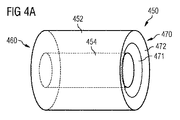
450 光偏向要素
452 基材
454 貫通口
460 光入口面
465 凸状湾曲
470 光出口面
471 円錐形面
472 円錐形面
511 1次光線束
517 光軸
522 2次光線束
522a 第1の円錐面形状の光構造
522b 第2の円錐面形状の光構造
522c 第3の円錐面形状の光構造
550 光偏向要素
552 基材
554a 円形遮光要素
565a 集光レンズ
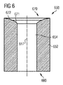
617 光軸
650 光偏向要素
652 基材
654 中心孔
660 光入口面
670 光出口面
671 第1の環状部分
672 第2の環状部分
717 光軸
750 光偏向要素
752 基材
754 中心孔
760 光入口面
761 第1の環状部分
762 第2の環状部分
770 光出口面
771 第1の環状部分
772 第2の環状部分
d 空洞直径
r 光軸からの平均半径距離
α 結像角
β 投射角(照明角)
θ 三角測量角度
Δl 長さ距離
Claims (20)
- 人間または動物の生体の耳道の少なくとも一部を3次元測定するための、光偏向要素(450)の光軸(417)に対して同軸に扇形に広げられて空間的に構造化された光線束(422)を屈折により発生させる光偏向要素であって、
光偏向要素(450)が、少なくとも部分的に光透過性材料から作られた基材(452)を有し、その基材が光入口面(460)および光出口面(470)を有し、
光入口面(460)は、基材(452)内に1次光線束(411)が入射可能であるように構成され、
光出口面(470)は光偏向要素(450)の光軸(417)に関して円筒対称の輪郭を有し、その輪郭が基材(452)に凹みを定め、
光偏向要素(450)が、空間的に構造化された光線束の光構造をこの光偏向要素(450)により耳道の内壁に集光可能なように形成されている光偏向要素。 - 前記輪郭が第1の環状部分(471)を有し、第1の環状部分(471)が実質的に基材の内部に向けられた円錐の第1の円錐面の少なくとも一部分の形状を有し、
第1の円錐面の円錐面線と光軸(417)とが第1の角度を形成している請求項1記載の光偏向要素。 - 前記輪郭が、半径方向において第1の環状部分(471)の外側に配置されている第2の環状部分(472)を有し、第2の環状部分(472)が実質的に円錐台の第2の円錐面の形状を有し、
第2の円錐面の円錐面線と光軸(417)とが前記第1の角度とは異なる第2の角度を形成している請求項2記載の光偏向要素。 - 前記輪郭が、半径方向において第2の環状部分(472)の外側に配置されている少なくとも1つの第3の環状部分を有し、第3の環状部分が実質的に円錐台の第3の円錐面の形状を有し、
第3の円錐面の円錐面線と光軸とが前記第2の角度と異なる第3角度を形成している請求項3記載の光偏向要素。 - 前記第1の角度と直角との間の角度差は、前記第2の角度と直角との間の角度差よりも大きい請求項3又は4記載の光偏向要素。
- 前記第1の角度と直角との間の角度差は、前記第2の角度と直角との間の角度差よりも小さい請求項3又は4記載の光偏向要素。
- 第1の環状部分(471)が基材の内部に向けられた円錐の第1の円錐面の少なくとも一部分の形状を有し、
第2の環状部分(472)が円錐台の第2の円錐面の形状を有し、および/または
第3の環状部分が円錐台の第3の円錐面の形状を有する請求項4に記載の光偏向要素。 - 第1の環状部分(671)、第2の環状部分(672)および第3の環状部分のうちの少なくとも1つの環状部分は湾曲した表面を有する請求項4に記載の光偏向要素。
- 基材(452)が筒の外形を有する請求項1乃至8の1つに記載の光偏向要素。
- 光入口面(460)が凸状湾曲(465)を有する請求項1乃至9の1つに記載の光偏向要素。
- 光入口面(760)が、湾曲した第1の環状部分(761)と少なくとも1つの湾曲した第2の環状部分(762)とを有する請求項1乃至9の1つに記載の光偏向要素。
- 基材(452)が、光軸(417)に対して同軸に延びた貫通口(454)を有する請求項1乃至11の1つに記載の光偏向要素。
- 前記貫通口(454)が、光軸(417)に対して同軸に配置された円筒の形状を有する中心孔(454)である請求項12記載の光偏向要素。
- 対象物内に形成されている空洞(125)の3次元測定、特に人間または動物の生体の耳道(125)の3次元測定のための光学式測定装置であって、
光学式測定装置(100)は、
照明ビーム通路(116)に沿って照明光(111)を送出するように構成された光源(110)と、
請求項1乃至13の1つに記載の光偏向要素(150,450)とを有し、
この光偏向要素(150,450)は、送出された照明光(111)を、空間的に次のように、すなわち光偏向要素(150,450)の光軸(117,417)の周りを取り巻きかつ空洞(125)の大きさおよび形状に応じた形状を有する少なくとも1つの照明線(128)が内壁に発生されるように構造化し、
光学式測定装置(100)は、さらに、少なくとも1つの照明線(128)を結像ビーム通路(136)を介して三角測量角度(θ)で検出するカメラ(145)を有する光学式測定装置。 - カメラ(145)の後に接続されている評価ユニット(146)を有し、評価ユニット(146)は、カメラ(145)によって検出された少なくとも1つの照明線(149)の画像処理によって、空洞(125)の少なくとも一部の大きさおよび形状が自動的に決定可能であるように構成されている請求項14記載の光学式測定装置。
- 照明ビーム通路内に配置されている投射レンズ(112)を付加的に有する請求項14又は15記載の光学式測定装置。
- 光偏向要素(120)の光軸(117)に傾斜角度で配置されたビームスプリッタ(113)を付加的に有し、ビームスプリッタ(113)は、
照明ビーム通路(116)の対象物側部分が光軸(117)に対して平行に延びるように照明ビーム通路(116)の向きを変えるか、または
結像ビーム通路の画像側部分が光軸に対して角度を持って延びるように結像ビーム通路の向きを変える請求項14乃至16の1つに記載の光学式測定装置。 - 照明光(111)が光軸(117)に対して平行に案内されている照明ビーム通路(116)の少なくとも一部は、光軸(117)の中心に延びる結像ビーム通路(136)の周りを取り巻くように構成されている請求項14乃至17の1つに記載の光学式測定装置。
- 結像ビーム通路(136)内に配置されている光案内装置(135)を付加的に有し、光案内装置(135)が照明線(128)の2次元画像(148)をカメラ(145)に伝達するように構成されている請求項14乃至18の1つに記載の光学式測定装置。
- 同軸に扇形に広げられて空間的に構造化された光線束(422)の発生方法であって、
請求項1乃至13の1つに記載の光偏向要素(450)に1次光線束(411)が送出され、1次光線束(411)が光入口面(460)で光偏向要素(450)の基材(452)内に入射し、2次光線束(422)として光出口面(470)で基材(452)から出射し、2次光線束(422)が少なくとも1つの円錐面形状の光構造(422a,422b)を有する、光線束の発生方法。
Applications Claiming Priority (3)
| Application Number | Priority Date | Filing Date | Title |
|---|---|---|---|
| DE102007005388.8 | 2007-02-02 | ||
| DE102007005388A DE102007005388A1 (de) | 2007-02-02 | 2007-02-02 | Refraktive Erzeugung eines konzentrisch aufgefächerten strukturierten Lichtstrahlenbündels, optische Messvorrichtung mit refraktivem Ablenkungselement |
| PCT/EP2008/050929 WO2008092820A1 (de) | 2007-02-02 | 2008-01-28 | Refraktive erzeugung eines konzentrisch aufgefächerten strukturierten lichtstrahlenbündels, optische messvorrichtung mit refraktivem ablenkungselement |
Publications (3)
| Publication Number | Publication Date |
|---|---|
| JP2010518367A JP2010518367A (ja) | 2010-05-27 |
| JP2010518367A5 JP2010518367A5 (ja) | 2010-08-05 |
| JP5383509B2 true JP5383509B2 (ja) | 2014-01-08 |
Family
ID=39246744
Family Applications (1)
| Application Number | Title | Priority Date | Filing Date |
|---|---|---|---|
| JP2009547650A Expired - Fee Related JP5383509B2 (ja) | 2007-02-02 | 2008-01-28 | 光線束の発生方法、光偏向要素および光学式測定装置 |
Country Status (7)
| Country | Link |
|---|---|
| US (1) | US8040527B2 (ja) |
| EP (1) | EP2115385A1 (ja) |
| JP (1) | JP5383509B2 (ja) |
| CN (1) | CN101600935A (ja) |
| AU (1) | AU2008209810B2 (ja) |
| DE (1) | DE102007005388A1 (ja) |
| WO (1) | WO2008092820A1 (ja) |
Families Citing this family (17)
| Publication number | Priority date | Publication date | Assignee | Title |
|---|---|---|---|---|
| DE102009014463A1 (de) * | 2009-03-23 | 2010-09-30 | Siemens Medical Instruments Pte. Ltd. | Vorrichtung und Verfahren zum Messen der Distanz zum Trommelfell |
| DE102009034993A1 (de) | 2009-07-28 | 2011-02-10 | Siemens Medical Instruments Pte. Ltd. | Vorrichtung und Verfahren zum Erfassen der Gestalt eines Ohrabschnitts |
| US7995214B2 (en) | 2009-07-28 | 2011-08-09 | Siemens Medical Instruments Pte. Ltd. | Apparatus and method for recording the shape of an ear section |
| DE102009043538A1 (de) | 2009-09-30 | 2011-03-31 | Siemens Aktiengesellschaft | Messendoskop |
| DE102009043523A1 (de) * | 2009-09-30 | 2011-04-07 | Siemens Aktiengesellschaft | Endoskop |
| DE102010025752A1 (de) * | 2010-06-30 | 2012-01-05 | Siemens Aktiengesellschaft | Endoskop |
| US8900126B2 (en) | 2011-03-23 | 2014-12-02 | United Sciences, Llc | Optical scanning device |
| US20130110005A1 (en) * | 2011-10-27 | 2013-05-02 | Covidien Lp | Point size light illumination in metrology systems for in-situ surgical applications |
| US9113822B2 (en) | 2011-10-27 | 2015-08-25 | Covidien Lp | Collimated beam metrology systems for in-situ surgical applications |
| US8900125B2 (en) | 2012-03-12 | 2014-12-02 | United Sciences, Llc | Otoscanning with 3D modeling |
| WO2014164418A1 (en) | 2013-03-11 | 2014-10-09 | North Carolina State University | Functionalized environmentally benign nanoparticles |
| US9351643B2 (en) | 2013-03-12 | 2016-05-31 | Covidien Lp | Systems and methods for optical measurement for in-situ surgical applications |
| US9605954B2 (en) * | 2013-03-15 | 2017-03-28 | Flex Instrument Co., Ltd. | Distance measuring laser pointer |
| US9599697B2 (en) * | 2014-04-15 | 2017-03-21 | The Johns Hopkins University | Non-contact fiber optic localization and tracking system |
| DE102015201561A1 (de) | 2015-01-29 | 2016-08-04 | Rolls-Royce Deutschland Ltd & Co Kg | Messkopf einer endoskopischen Vorrichtung und Verfahren zur Inspektion und Messung eines Objektes |
| CN110891471B (zh) * | 2018-03-21 | 2022-11-18 | 卡普索影像公司 | 采用结构光提供生理特征尺寸测量的内窥镜 |
| CN115388812B (zh) * | 2022-10-27 | 2023-05-02 | 成都量芯集成科技有限公司 | 一种光电式电钻测量装置的测量方法 |
Family Cites Families (22)
| Publication number | Priority date | Publication date | Assignee | Title |
|---|---|---|---|---|
| US4013342A (en) * | 1975-12-19 | 1977-03-22 | Narodny Leo H | Keyboard using optical switching |
| GB1499359A (en) | 1975-12-23 | 1978-02-01 | Standard Telephones Cables Ltd | Optical fibre connectors |
| GB1569614A (en) * | 1976-02-03 | 1980-06-18 | Standard Telephones Cables Ltd | Optical fibre connectors |
| US20020045811A1 (en) * | 1985-03-22 | 2002-04-18 | Carter Kittrell | Laser ablation process and apparatus |
| JPH01191801A (ja) * | 1988-01-28 | 1989-08-01 | Sumitomo Electric Ind Ltd | 集光レンズ |
| JPH04122838A (ja) * | 1990-09-14 | 1992-04-23 | Osaka Gas Co Ltd | 管路内観察装置のライトガイド |
| JPH07275261A (ja) | 1994-04-11 | 1995-10-24 | Morita Mfg Co Ltd | 照明装置内蔵型歯科用ハンドピース |
| JPH07286828A (ja) * | 1994-04-19 | 1995-10-31 | Kobe Steel Ltd | 管内検査装置 |
| US6423055B1 (en) * | 1999-07-14 | 2002-07-23 | Cardiofocus, Inc. | Phototherapeutic wave guide apparatus |
| DE19742264C2 (de) * | 1997-09-25 | 2001-09-20 | Vosseler Erste Patentverwertun | Endoskop |
| DE19803679C2 (de) | 1998-01-30 | 2000-03-09 | Vosseler Zweite Patentverwertu | Vorrichtung zur optischen Abtastung eines Objekts, insbesondere Endoskop |
| JP2001296114A (ja) * | 2000-04-12 | 2001-10-26 | Stl Corp | 表面観察装置 |
| US7625335B2 (en) * | 2000-08-25 | 2009-12-01 | 3Shape Aps | Method and apparatus for three-dimensional optical scanning of interior surfaces |
| EP1392155B1 (en) * | 2001-05-17 | 2012-09-05 | Oticon A/S | Method and apparatus for obtaining position data relating to a probe in the ear canal |
| EP1392164B1 (en) * | 2001-05-17 | 2012-07-25 | Oticon A/S | Method for obtaining geometrical data relating to the ear canal of the human body |
| AU2002218934A1 (en) * | 2002-01-21 | 2002-03-26 | Phonak Ag | Method for the reconstruction of the geometry of the inner surface of a cavity |
| DE10231969B4 (de) * | 2002-07-15 | 2004-09-30 | Siemens Ag | Optisches Element zur Formung eines Lichtstrahls und Verfahren zum Bearbeiten von Objekten mittels Laserstrahlen |
| US20040181128A1 (en) * | 2003-03-11 | 2004-09-16 | Masters Martin W. | Determining the geometry and dimensions of a three-dimensional object |
| CN1897870A (zh) | 2003-12-22 | 2007-01-17 | 皇家飞利浦电子股份有限公司 | 用于进行正交偏振光谱成像(opsi)的装置和方法 |
| DE102005034991A1 (de) * | 2004-09-08 | 2006-04-13 | Carl Zeiss Smt Ag | Strahlumformsystem für ein Beleuchtungssystem einer mikrolithographischen Projektionsbelichtungsanlage |
| DE102004058044B4 (de) * | 2004-12-01 | 2014-02-06 | Friedrich-Schiller-Universität Jena | Ortsfrequenzfiltervorrichtung und Verfahren zur Ortsfrequenzfilterung von Laserstrahlen |
| JP4380663B2 (ja) * | 2006-06-08 | 2009-12-09 | コニカミノルタセンシング株式会社 | 三次元形状測定方法、装置、及びフォーカス調整方法 |
-
2007
- 2007-02-02 DE DE102007005388A patent/DE102007005388A1/de not_active Withdrawn
-
2008
- 2008-01-28 EP EP08708252A patent/EP2115385A1/de not_active Withdrawn
- 2008-01-28 AU AU2008209810A patent/AU2008209810B2/en not_active Ceased
- 2008-01-28 US US12/525,361 patent/US8040527B2/en not_active Expired - Fee Related
- 2008-01-28 JP JP2009547650A patent/JP5383509B2/ja not_active Expired - Fee Related
- 2008-01-28 CN CNA2008800034871A patent/CN101600935A/zh active Pending
- 2008-01-28 WO PCT/EP2008/050929 patent/WO2008092820A1/de active Application Filing
Also Published As
| Publication number | Publication date |
|---|---|
| US20100020333A1 (en) | 2010-01-28 |
| WO2008092820A1 (de) | 2008-08-07 |
| AU2008209810B2 (en) | 2011-07-07 |
| DE102007005388A1 (de) | 2008-08-07 |
| EP2115385A1 (de) | 2009-11-11 |
| CN101600935A (zh) | 2009-12-09 |
| AU2008209810A1 (en) | 2008-08-07 |
| JP2010518367A (ja) | 2010-05-27 |
| US8040527B2 (en) | 2011-10-18 |
Similar Documents
| Publication | Publication Date | Title |
|---|---|---|
| JP5383509B2 (ja) | 光線束の発生方法、光偏向要素および光学式測定装置 | |
| US11019327B2 (en) | Endoscope employing structured light providing physiological feature size measurement | |
| JP6818702B2 (ja) | 光学検査装置及び光学検査方法 | |
| US20100060718A1 (en) | Measuring a hollow space by means of cylindrically symmetrical triangulation | |
| US8049901B2 (en) | Measuring device and measuring method | |
| JP5815531B2 (ja) | 内視鏡および表面のトポグラフィの測定方法 | |
| US20100191125A1 (en) | Apparatus and method for obtaining geometrical data relating to a cavity | |
| KR100624256B1 (ko) | 투명한 튜브의 외경과 내경을 측정하기 위한 장치 및 방법 | |
| KR20040047791A (ko) | 타겟 표면 이미지의 발생 방법 및 포착 시스템 | |
| JP6891345B2 (ja) | 構造化光を生理学的特徴サイズ測定に利用する内視鏡 | |
| JP2018004624A (ja) | 距離計測機能付き内視鏡および距離計測方法 | |
| JP5404933B2 (ja) | 測定内視鏡 | |
| JP2010236870A (ja) | 孔形状測定方法 | |
| US8456521B2 (en) | Triangulation camera device and triangulation imaging method | |
| JP2006292513A (ja) | 屈折率分布型レンズの屈折率分布測定方法 | |
| US20200033584A1 (en) | Pattern projector using rotational superposition of multiple optical diffraction elements and 3d endoscope having the same | |
| JP7043577B2 (ja) | 光学検査装置、方法及びプログラム | |
| CN105765438A (zh) | 用于使样本成像的光学布置 | |
| JP2005331413A (ja) | 距離画像取得システム | |
| KR102066129B1 (ko) | 도트 어레이를 이용하는 3차원 정보 생성 장치 및 방법 | |
| JP7185807B2 (ja) | パターンプロジェクタを有するボアスコープ | |
| JPH0643893B2 (ja) | 距離測定装置 | |
| JPH0789058B2 (ja) | 距離測定装置 | |
| IT202100007469A1 (it) | Camera scheimpflug perfezionata, in particolare ma non necessariamente per uso oftalmico, con sensore di tipo cmos | |
| JPH0789057B2 (ja) | 距離測定装置 |
Legal Events
| Date | Code | Title | Description |
|---|---|---|---|
| A521 | Written amendment |
Free format text: JAPANESE INTERMEDIATE CODE: A523 Effective date: 20100621 |
|
| A621 | Written request for application examination |
Free format text: JAPANESE INTERMEDIATE CODE: A621 Effective date: 20100621 |
|
| RD03 | Notification of appointment of power of attorney |
Free format text: JAPANESE INTERMEDIATE CODE: A7423 Effective date: 20100621 |
|
| A977 | Report on retrieval |
Free format text: JAPANESE INTERMEDIATE CODE: A971007 Effective date: 20120222 |
|
| A131 | Notification of reasons for refusal |
Free format text: JAPANESE INTERMEDIATE CODE: A131 Effective date: 20120228 |
|
| A521 | Written amendment |
Free format text: JAPANESE INTERMEDIATE CODE: A523 Effective date: 20120528 |
|
| A131 | Notification of reasons for refusal |
Free format text: JAPANESE INTERMEDIATE CODE: A131 Effective date: 20121106 |
|
| TRDD | Decision of grant or rejection written | ||
| A01 | Written decision to grant a patent or to grant a registration (utility model) |
Free format text: JAPANESE INTERMEDIATE CODE: A01 Effective date: 20130903 |
|
| A61 | First payment of annual fees (during grant procedure) |
Free format text: JAPANESE INTERMEDIATE CODE: A61 Effective date: 20131001 |
|
| R150 | Certificate of patent or registration of utility model |
Free format text: JAPANESE INTERMEDIATE CODE: R150 |
|
| R250 | Receipt of annual fees |
Free format text: JAPANESE INTERMEDIATE CODE: R250 |
|
| R250 | Receipt of annual fees |
Free format text: JAPANESE INTERMEDIATE CODE: R250 |
|
| LAPS | Cancellation because of no payment of annual fees |