JP5259240B2 - Multilayer flexible printed wiring board and manufacturing method thereof - Google Patents
Multilayer flexible printed wiring board and manufacturing method thereof Download PDFInfo
- Publication number
- JP5259240B2 JP5259240B2 JP2008110232A JP2008110232A JP5259240B2 JP 5259240 B2 JP5259240 B2 JP 5259240B2 JP 2008110232 A JP2008110232 A JP 2008110232A JP 2008110232 A JP2008110232 A JP 2008110232A JP 5259240 B2 JP5259240 B2 JP 5259240B2
- Authority
- JP
- Japan
- Prior art keywords
- layer
- conductive layer
- flexible printed
- wiring board
- printed wiring
- Prior art date
- Legal status (The legal status is an assumption and is not a legal conclusion. Google has not performed a legal analysis and makes no representation as to the accuracy of the status listed.)
- Active
Links
Images


Classifications
-
- H—ELECTRICITY
- H05—ELECTRIC TECHNIQUES NOT OTHERWISE PROVIDED FOR
- H05K—PRINTED CIRCUITS; CASINGS OR CONSTRUCTIONAL DETAILS OF ELECTRIC APPARATUS; MANUFACTURE OF ASSEMBLAGES OF ELECTRICAL COMPONENTS
- H05K3/00—Apparatus or processes for manufacturing printed circuits
- H05K3/46—Manufacturing multilayer circuits
- H05K3/4644—Manufacturing multilayer circuits by building the multilayer layer by layer, i.e. build-up multilayer circuits
- H05K3/4652—Adding a circuit layer by laminating a metal foil or a preformed metal foil pattern
Landscapes
- Production Of Multi-Layered Print Wiring Board (AREA)
Description
本発明は、多層フレキシブルプリント配線板およびその製造方法に関し、特に可撓性ケーブル部を有するビルドアップ型多層フレキシブルプリント配線板およびその製造方法に関する。 The present invention relates to a multilayer flexible printed wiring board and a manufacturing method thereof, and more particularly to a build-up type multilayer flexible printed wiring board having a flexible cable portion and a manufacturing method thereof.
近年、電子機器、特に携帯電話の高機能化はめざましく、それに伴い多層フレキシブルプリント配線板に実装される部品もチップサイズパッケージ(Chip-Size Package,Chip-Scale Packageとも呼ばれ、以下、CSPと称する。)に置き換わり、高機能かつ高密度にパッケージングし、基板サイズを大きくすることなく高機能を付加しようという流れがある。 2. Description of the Related Art In recent years, electronic devices, particularly mobile phones, have been highly functionalized, and accordingly, components mounted on a multilayer flexible printed wiring board are also called chip-size packages (Chip-Size Package, Chip-Scale Package, hereinafter referred to as CSP). )), There is a trend of packaging with high functionality and high density and adding high functionality without increasing the board size.
このCSPのパッドピッチも、当初は0.8mmピッチであったものが、近年では0.4mmピッチ以下の狭ピッチなものの要求も出始めている。中でも10パッド×10パッド以上のパッド数の、CSPのパッドがフルグリッドで配置されている狭ピッチCSPを搭載することは、従来の多層フレキシブルプリント配線板では非常に困難であった。 Although the pad pitch of the CSP was originally 0.8 mm pitch, in recent years, there is a demand for a narrow pitch of 0.4 mm pitch or less. In particular, it is very difficult for a conventional multilayer flexible printed wiring board to mount a narrow pitch CSP having 10 pads × 10 pads or more and CSP pads arranged in a full grid.
ここで、多層フレキシブルプリント配線板に狭ピッチCSPを搭載する上での必須要件を見ると、以下のようなものがある。
(1)CSP実装パッドに貫通孔がないこと
実装に必要な半田が流れないようにするためである。
(2)導通部の高密度配置が可能なこと
狭ピッチCSP実装パッドから下の配線層に直接接続するため、要求される最小ピッチとしては搭載するCSPのパッドピッチと同じピッチが必要となる。
(3)微細配線形成能力
外層、内層を問わず、100パッド以上の多くのパッドからの配線引き回しが必要なためである。また、CSP実装パッド間に引き回せる配線の本数が、搭載可能なCSPのスペックを決める重要なファクターである。特に、CSP搭載に際しては、CSP実装パッドの存在する外層の配線より下の内層の配線の微細化が有効である。
(4)CSP実装パッドの平坦性
CSPを多層フレキシブルプリント配線板上にフェースダウンでフリップチップ実装する際に、CSP側のパッド上の半田ボールの高さで、CSP実装パッドの凹凸を吸収する必要があるためである。多層フレキシブルプリント配線板においては、各層の導体層の厚みによる段差を接着材等で充填し、平坦性を確保する必要がある。
Here, the essential requirements for mounting the narrow pitch CSP on the multilayer flexible printed wiring board are as follows.
(1) There is no through hole in the CSP mounting pad so that solder necessary for mounting does not flow.
(2) Capable of high-density arrangement of conductive portions Since the direct connection is made from the narrow pitch CSP mounting pad to the lower wiring layer, the required minimum pitch is the same as the pad pitch of the CSP to be mounted.
(3) Ability to form fine wiring This is because it is necessary to route wiring from many pads of 100 pads or more regardless of the outer layer or the inner layer. Further, the number of wirings that can be routed between CSP mounting pads is an important factor that determines the specifications of CSPs that can be mounted. In particular, when mounting a CSP, it is effective to miniaturize the inner layer wiring below the outer layer wiring where the CSP mounting pad exists.
(4) Flatness of CSP mounting pad When flip-chip mounting a CSP face down on a multilayer flexible printed wiring board, it is necessary to absorb the unevenness of the CSP mounting pad with the height of the solder ball on the pad on the CSP side. Because there is. In a multilayer flexible printed wiring board, it is necessary to fill a step due to the thickness of each conductive layer with an adhesive or the like to ensure flatness.
このような要求を満足するフレキシブルプリント配線板として、特許文献1に記載の6層構造の多層フレキシブルプリント配線板がある。そして、携帯電話やデジタルビデオカメラ等のメイン基板においては、6層構造では配線層の層数が不足し、8層構造の基板が用いられることが多くなっている。
As a flexible printed wiring board that satisfies such requirements, there is a multilayer flexible printed wiring board having a six-layer structure described in
8層構造の基板を用いる他の理由としては、基板の第1導電層に部品を実装し、第2導電層にグランド層を配置し、第3導電層で信号線の引き回しを行う場合があるからである。信号線の引き回しは、CSPのピン間に通せる配線の本数で決まるため、CSP搭載ランドの直下に配したビアホールで下層の信号線に接続する構造が最も高密度化に適している。 Another reason for using an eight-layer substrate is that a component is mounted on the first conductive layer of the substrate, a ground layer is disposed on the second conductive layer, and signal lines are routed on the third conductive layer. Because. Since the routing of the signal line is determined by the number of wirings that can be passed between the pins of the CSP, a structure in which the signal line is connected to the lower layer signal line through the via hole arranged immediately below the CSP mounting land is most suitable for increasing the density.
さらに、信号線のある配線層のランド間に多くの本数の信号線を通すことで、高密度CSPに対応できる。このため、上述のランド径をできるだけ小さくし、信号線を微細に形成する必要がある。 Furthermore, high-density CSP can be accommodated by passing a large number of signal lines between lands in the wiring layer with signal lines. For this reason, it is necessary to make the above-mentioned land diameter as small as possible and to form a fine signal line.
図5は、従来の6層構造の多層フレキシブルプリント配線板の構造を示したものである。この配線板は、ビルドアップ層を1層ずつ設けた8層構造である。 FIG. 5 shows the structure of a conventional multilayer flexible printed wiring board having a six-layer structure. This wiring board has an eight-layer structure in which build-up layers are provided one by one.
この配線板を製造するには、まず図5に示すようにポリイミド等の可撓性絶縁ベース材の両面に銅箔を有する両面銅張積層板を出発材料とした両面フレキシブルプリント配線板101を用意する。
In order to manufacture this wiring board, first, as shown in FIG. 5, a double-sided flexible printed
次いで、両面フレキシブルプリント配線板101へのビルドアップ層とする両面フレキシブル配線基材102を用意し、その内層側にカバーレイ103を形成する。接着材104を介し、内層側にカバーレイ103を施した両面フレキシブル配線基材102と両面フレキシブルプリント配線板101とを貼り合せ、6層の配線基材105とする。
Next, a double-sided
次に6層の配線基材105に対し、レーザ加工等の手法で導通用孔を形成し、ビアホールめっきを行うことで、層間導通を得る。さらに1層ずつビルドアップを行うため、ビアホールめっきにビアフィルめっきを選択したことで、6層の配線基材105のビア上にビルドアップ層のビアを重ねて形成する、所謂、スタックビア構造とすることが可能である。 Next, a conduction hole is formed in the six-layer wiring substrate 105 by a technique such as laser processing and via hole plating is performed to obtain interlayer conduction. Furthermore, since build-up is performed layer by layer, via-fill plating is selected for via-hole plating, so that a build-up layer via is formed on the vias of the six-layer wiring substrate 105 to form a so-called stack via structure. It is possible.
6層の配線基材105上に、接着材106を介して片面フレキシブルプリント配線板107を貼り合せることによりビルドアップする。その後、レーザ加工等の手法で導通用孔を形成し、ビアホールめっきを行い、外層のパターンを形成することで8層構造の多層フレキシブルプリント配線板108を得る。
しかしながら、上述の6層構造の多層フレキシブルプリント配線板に、ビルドアップ層を1層ずつ設けた8層構造の多層フレキシブルプリント配線板を用いた場合には、ビルドアップ層を積層する際の位置精度、コア基板となる6層構造の多層フレキシブルプリント配線板を作製する際の基板寸法伸縮により、ランド径を小さくすることができず、CSPのピン間に配線を通すための制限となっている。 However, when the multilayer flexible printed wiring board having an eight-layer structure in which one build-up layer is provided for the multilayer flexible printed wiring board having the six-layer structure described above, positional accuracy when the build-up layers are laminated The land diameter cannot be reduced due to the expansion and contraction of the substrate dimensions when producing a multilayer flexible printed wiring board having a six-layer structure as a core substrate, and this is a limitation for passing wiring between CSP pins.
さらに、6層構造の多層フレキシブルプリント配線板に1層ビルドアップするためには、コア基板のビアホールをビアフィルめっき等で穴埋めするか、ビアホールを充填可能な厚い積層接着材を用いるかする必要がある。 Further, in order to build up one layer on a multilayer flexible printed wiring board having a 6-layer structure, it is necessary to fill the via hole of the core substrate with via fill plating or to use a thick laminated adhesive capable of filling the via hole. .
このため、ビルドアップ層の層間接続信頼性の確保が困難になったり、積層接着材が厚いことから、硬化する際の基板寸法伸縮量が大きかったりする、という問題も生じ、8層構造でも好適に高密度CSPを搭載可能な多層フレキシブルプリント配線板を製造することは困難である。 For this reason, it becomes difficult to ensure the interlayer connection reliability of the build-up layer, and since the laminated adhesive is thick, there is a problem that the amount of expansion and contraction of the substrate size at the time of curing also arises. It is difficult to manufacture a multilayer flexible printed wiring board capable of mounting a high-density CSP.
本発明は、上述の点を考慮してなされたもので、狭ピッチな高密度CSPを搭載可能な多層フレキシブルプリント配線板、およびこの配線板を安価に安定的に製造する方法を提供することを目的とする。 The present invention has been made in consideration of the above-described points, and provides a multilayer flexible printed wiring board capable of mounting a high-density CSP with a narrow pitch, and a method for stably manufacturing the wiring board at low cost. Objective.
上記目的達成のため、本願では、次の各発明を提供する。 In order to achieve the above object, the present invention provides the following inventions.
第1の発明によれば、
両面に配線パターンを有するコア基板の少なくとも片面に3層構造のビルドアップ層を有する多層フレキシブルプリント配線板において、
前記ビルドアップ層の外層側から1層目の第1導電層には、チップサイズパッケージを実装する実装パッドを有し、
前記ビルドアップ層の外層側から2層目の第2導電層には、少なくとも前記チップサイズパッケージを搭載する領域の直下にグランド層を有し、
前記ビルドアップ層の外層側から3層目の第3導電層には、前記実装パッドから、第2導電層のグランド層をスキップするスキップビアホールを介して導通された、信号回路を引き回すための配線パターンを有し、
前記スキップビアホールが有底のブラインドビアホールであって、該ブラインドビアホールの底が第1導電層の前記実装パッドの裏面に接しているとともに、前記ビルドアップ層と前記コア基板とを導通するビアホールを前記スキップビアホールとは別に有し、
前記ビルドアップ層と一体化した可撓性ケーブル部を有することを特徴とする。
ことを特徴とする。
According to the first invention,
In a multilayer flexible printed wiring board having a build-up layer having a three-layer structure on at least one side of a core substrate having a wiring pattern on both sides,
The first conductive layer that is the first layer from the outer layer side of the build-up layer has a mounting pad for mounting a chip size package,
The second conductive layer, which is the second layer from the outer layer side of the build-up layer, has a ground layer at least immediately below the region where the chip size package is mounted,
Wiring for routing a signal circuit, which is conducted from the mounting pad through a skip via hole that skips the ground layer of the second conductive layer, to the third conductive layer that is the third layer from the outer layer side of the buildup layer Has a pattern,
The skip via hole is a bottomed blind via hole, and the bottom of the blind via hole is in contact with the back surface of the mounting pad of the first conductive layer, and the via hole that conducts the build-up layer and the core substrate Apart from the skip beer hall,
It has the flexible cable part integrated with the said buildup layer, It is characterized by the above-mentioned.
It is characterized by that.
また、第2の発明によれば、
両面に配線パターンを有するコア基板の少なくとも片面に3層構造のビルドアップ層を有する多層フレキシブルプリント配線板の製造方法において、
a) 両面型の可撓性配線基材の一方の面における導通用孔の形成部位にレーザ加工用の開口を形成し、他方の面にグランド層及び導通用孔の形成部位の開口を含む配線パターンを形成する工程
b) 前記可撓性配線基材の配線パターンを形成した面と片面型の可撓性配線基材の可撓性絶縁ベース材側の面とを接着材を介して貼り合せ、3層構造の配線基材を形成する工程
c) 前記3層構造の配線基材の外層側から3層目の導電層となる第3導電層の導通用孔の形成部位の開口に対してレーザ加工を行い、外層側から1層目の導電層となる第1導電層まで達する有底の導通用孔を形成する工程
d) 前記導通用孔に対して導電化処理を行い、電解めっきによりブラインドビアホールを形成する工程
e) 前記第3導電層に配線パターンを形成する工程
f) 前記第3導電層の配線パターン上にカバーレイを形成する工程
g) 前記ビルドアップ層のカバーレイを形成した側を別途製作したコア基板側へ向け、前記コア基板に接着材を介し、積層する工程
h) 前記積層配線基材に対し、前記第1導電層の導通用孔形成部位から、コア基板まで達する導通用孔を形成する工程
i) 前記導通用孔に対し、導電化処理を行い電解めっきによりビアホールを形成する工程
をそなえたことを特徴とする。
According to the second invention,
In the method for producing a multilayer flexible printed wiring board having a build-up layer having a three-layer structure on at least one side of a core substrate having a wiring pattern on both sides,
a) Wiring including an opening for laser processing in a portion where a conduction hole is formed on one surface of a double-sided flexible wiring substrate, and an opening where a ground layer and a conduction hole are formed on the other surface Pattern forming process
b) The surface of the flexible wiring substrate on which the wiring pattern is formed and the surface of the single-sided flexible wiring substrate on the side of the flexible insulating base material are bonded to each other with an adhesive. Process for forming wiring substrate
c) Laser processing is performed on the opening portion of the third conductive layer which is the third conductive layer from the outer layer side of the wiring substrate having the three-layer structure, and the first layer is formed from the outer layer side. Forming a bottomed conduction hole reaching the first conductive layer to be a conductive layer
d) Conducting the conductive holes and forming blind via holes by electrolytic plating
e) forming a wiring pattern on the third conductive layer
f) forming a coverlay on the wiring pattern of the third conductive layer
g) A step of laminating the side of the build-up layer on the core substrate facing the separately manufactured core substrate side through an adhesive.
h) A step of forming a conduction hole reaching the core substrate from the conduction hole forming portion of the first conductive layer on the laminated wiring substrate.
i) The method is characterized in that the conductive hole is subjected to a conductive treatment and a via hole is formed by electrolytic plating.
これらの特徴により、本発明は次のような効果を奏する。 Due to these features, the present invention has the following effects.
本発明による多層フレキシブルプリント配線板は、第1導電層(CSP実装層)と第3導電層(信号層)とを位置合わせしていることから、第3導電層のランドを小径化でき、しかも第2導電層にはグランド層を配置することで電気特性を向上させることができる。CSP実装面はビアホールの底側となるため、平坦性が確保され、ビアホールの凹みの影響を受けることなく、好適にCSP実装が可能である。 In the multilayer flexible printed wiring board according to the present invention, since the first conductive layer (CSP mounting layer) and the third conductive layer (signal layer) are aligned, the land of the third conductive layer can be reduced in diameter, and The electrical characteristics can be improved by arranging a ground layer in the second conductive layer. Since the CSP mounting surface is on the bottom side of the via hole, flatness is ensured and CSP mounting can be suitably performed without being affected by the depression of the via hole.
また、この場合、ケーブルが第3導電層に配置可能であることから、最短距離で部品実装部を接続することができる。信号線が第2導電層にある場合には、ケーブルを第2導電層に配置することにも対応できる。さらに、両面のビルドアップ層を、コア基板を挟んで直接接続することにより、ビアホールやスルーホールを減らすこともできる。この結果、狭ピッチな高密度CSPを搭載可能な多層フレキシブルプリント配線板を安価かつ安定的に製造することができる。 In this case, since the cable can be arranged on the third conductive layer, the component mounting portions can be connected with the shortest distance. When the signal line is in the second conductive layer, the cable can be arranged in the second conductive layer. Furthermore, via holes and through holes can be reduced by directly connecting the build-up layers on both sides with the core substrate interposed therebetween. As a result, a multilayer flexible printed wiring board on which a high-density CSP having a narrow pitch can be mounted can be manufactured inexpensively and stably.
以下、添付図面を参照して本発明の実施例を説明する。 Embodiments of the present invention will be described below with reference to the accompanying drawings.
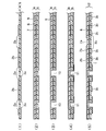
図1Aないし図1Dは、本発明に係る製造方法を示す工程図である。この工程により、ケーブル部を有する8層構造の多層フレキシブルプリント配線板の製造方法を示す。 1A to 1D are process diagrams showing a manufacturing method according to the present invention. The manufacturing method of the multilayer flexible printed wiring board of the 8-layer structure which has a cable part by this process is shown.
先ず、図1A(1)に示すように、両面銅張積層板4に対し、内層側の銅箔2のレーザ加工時のコンフォーマルマスク2aおよび回路パターン2bを形成する。両面銅張積層板4としては、例えばポリイミド等の可撓性絶縁ベース材1(ここでは、厚さ12.5μmのポリイミド)の両面に、厚さ12μmの銅箔2および3を有するものを用いる。
First, as shown in FIG. 1A (1), a
コンフォーマルマスク2aおよび回路パターン2bは、銅箔2をフォトファブリケーション手法のエッチングすることによって形成する。また、外層側となる銅箔3には、レーザ加工時のコンフォーマルマスク3aを形成する。併せて、後の第3導電層との位置合せマーク等を形成しておいてもよい。この工程により、配線基材5を得る。
The
次に図1A(2)に示すように、ポリイミド等の可撓性絶縁ベース材6(ここでは、厚さ12.5μmのポリイミド)の片面に厚さ12μmの銅箔7を有する、所謂、片面銅張積層板8に、必要に応じて位置合せ用のガイド等を型抜きし、配線基材5を積層するための接着材9を予め型抜きして位置合せを行う。接着材9を介し、両面の配線基材5と片面の配線基材をロールラミネータや平板プレス、真空プレス等を用いて積層する。ここまでの工程で、3層の多層配線基材を得る。
Next, as shown in FIG. 1A (2), a so-called single-sided copper having a 12 μm-
続いて、図1A(3)に示すように、コンフォーマルマスク7aを用いてレーザ加工を行い、導通用孔10を形成する。レーザ加工法に用いるレーザとしては、炭酸ガスレーザやYAGレーザ等の赤外レーザのほか、エキシマレーザやUV−YAGレーザ等の紫外レーザも選択可能である。
Subsequently, as shown in FIG. 1A (3), laser processing is performed using the
各導通用孔の径は、以下のように設定した。まず導通用孔10は、可撓性絶縁ベース材1および6に、この実施例1のように12.5μm厚のポリイミドを用いた場合、直径50μmでも製造可能で、信頼性を確保するための必要めっき厚が10μm程度であることから、ここでは直径50μmとした。
The diameter of each conduction hole was set as follows. First, the
この後、図1A(4)に示すように、導通用孔10を有する3層の多層配線基材に10μm程度の電解めっきを行って層間導通をとり、スキップビアホール11とした。ここでは、導通用孔以外にめっきを付けない、所謂、ボタンめっき手法を採用した。
Thereafter, as shown in FIG. 1A (4), the three-layer multilayer wiring substrate having the
次に図1A(5)に示すように、この3層の多層配線基材の外層側と内層側、すなわち、第1導電層7と第3導電層3に対し、両面の回路パターン7b,3cを形成する。第1導電層7にはレーザ加工時のコンフォーマルマスク7aを、第3導電層3にはレーザ加工時のコンフォーマルマスク3bおよび回路パターン3cをフォトファブリケーション手法によるエッチング手法により形成する。ここまでの工程で、3層のパターンを形成した配線基材12を得る。
Next, as shown in FIG. 1A (5), the
この時の両面の位置合せは、ベタの材料に対して行うため、材料の伸縮等に影響されず、高い位置精度を容易に確保できる。必要に応じて、高精度な位置合せが可能な露光機を用いることも可能である。 Since the alignment of both surfaces at this time is performed on the solid material, high positional accuracy can be easily ensured without being affected by the expansion and contraction of the material. If necessary, it is also possible to use an exposure machine capable of highly accurate alignment.
第1導電層7は部品実装面で、第2導電層2は主にグランド層となる、ほぼベタの配線層であり、第3導電層3は信号線として機能することを想定しているので、第1導電層7と第3導電層3との位置合せ精度がビアホールの受けランドの大きさ等に直結することから、高密度回路の形成においては重要である。
Since it is assumed that the first
ここでは、多ピンCSP等の高密度部品を搭載する箇所の実装部を、上述のスキップビアホール11のビア底側とすることを想定しており、実装面(第1導電層)はビアホールの凹みがなく、第3導電層3の信号線への直接接続が可能である。
Here, it is assumed that a mounting portion where a high-density component such as a multi-pin CSP is mounted is the via bottom side of the skip via
また、第3導電層3の回路パターンにはめっきを付けていないことから、屈曲ケーブルとしても機能させることが可能である。一方、第2導電層2と第1導電層7、第3導電層3の位置精度は、上述の第1導電層7と第3導電層3との位置合せほど重要ではなく、ビアホールの逃げやグランド用の径の大きな受けランドを形成できればよい。
In addition, since the circuit pattern of the third
無論、第1導電層7と第2導電層2との位置合せを重視する場合においては、それに合せて各層同士を位置合わせすればよい。
Of course, when importance is attached to the alignment between the first
次いで、図1B(6)に示すように、例えば12μm厚のポリイミドフィルム13の上に、厚さ25μmのアクリル・エポキシ等の接着材14を有する、所謂、カバーレイ15を用意する。
Next, as shown in FIG. 1B (6), for example, a so-called cover lay 15 having an adhesive 14 such as acrylic / epoxy having a thickness of 25 μm on a
3層のパターンを形成した配線基材12の第3導電層3側に、カバーレイ15を、真空プレス、真空ラミネータ等で貼り付ける。これにより、スキップビアホール11の内側も完全に接着材14が充填されるため、吸湿した状態でのリフロー工程においても膨れ等が発生することはない。ここまでの工程で、カバーレイ付きのビルドアップ層16を得る。
A cover lay 15 is attached to the third
ここで、図1A(1)から図1B(6)までの一連の工程は、全てロールトゥロールで連続的に流動可能であることから、自動化・少人化が可能で安価に生産可能である。 Here, since the series of steps from FIG. 1A (1) to FIG. 1B (6) can all flow continuously by roll-to-roll, it can be automated and reduced in number and can be produced at low cost. .
図1B(7)は、スキップビアホール11周辺を、実寸法比率にて示した拡大横断面図であり、実際のビアホールの大きさとカバーレイ15等の厚さとを対比できる。これにより、25μm厚のカバーレイ接着材14により、コンフォーマルマスク径50μmのスキップビアホール11に10μm厚のめっきを付けた孔の内部が充填可能であることが分かる。
FIG. 1B (7) is an enlarged cross-sectional view showing the periphery of the skip via
図1B(8)は、両面銅張積層板の反対面に積層される、カバーレイ付きのもう一つのビルドアップ層16bの構造を示している。
FIG. 1B (8) shows the structure of another build-
そして図1B(9)は、2つのビルドアップ層16,16bの間に挟まれるべき両面銅張積層板、すなわちコア基板21の構造を示している。この図1B(9)に示すように、両面銅張積層板に対し、導通用孔18をNCドリル等で形成すると共に、導通用孔18に対し、導電化処理とそれに続く電解めっき処理により層間導電路を形成する。
FIG. 1B (9) shows the structure of a double-sided copper clad laminate to be sandwiched between the two
両面銅張積層板は、ポリイミド等の可撓性絶縁ベース材17(ここでは、厚さ25μmのポリイミド)の両面に厚さ8μmの銅箔を有するものである。電解めっき処理では、10μm程度の電解めっき皮膜を形成する。ここまでの工程で、貫通型の導通部であるスルーホール18が形成される。
The double-sided copper-clad laminate has a copper foil having a thickness of 8 μm on both sides of a flexible insulating
さらに、両面の回路パターンをフォトファブリケーション手法により形成するためのレジスト層の形成、露光、現像、エッチング、レジスト層剥離等の一連の工程によって、回路パターン19および20を形成する。ここまでの工程で、両面型のコア基板21を得る。
Further, the
次に図1C(10)に示すように、カバーレイ付きのビルドアップ層16および16bを両面コア基板21にビルドアップするための接着材22を予め型抜きして位置合せを行う。
Next, as shown in FIG. 1C (10), the adhesive 22 for building up the build-up
そして、接着材20を介してカバーレイ付きのビルドアップ層と両面コア基板21とを真空プレス等で積層する。ここまでの工程で、多層配線基材23を得る。接着材22としては、ローフロータイプのプリプレグやボンディングシート等の流れ出しの少ないものが好ましい。接着材22の厚さは、15μm程度のものが選択できる。
And the buildup layer with a coverlay and the double-
続いて図1C(11)に示すように、コンフォーマルマスク2a,3a,7aを用いて、レーザ加工を行い、4層を接続するための4種類の導通用孔24,25を形成する。レーザ加工には、UV-YAGレーザ、炭酸レーザ、エキシマレーザ等を選択して使用することができる。
Subsequently, as shown in FIG. 1C (11), laser processing is performed using the
各導通用孔の径は、以下のように設定した。導通用孔24,25は、集積度および層間接続信頼性の問題があるが、この実施例1では、導体層8層のうち、2層目から7層目までは導体層厚みが10μm程度に薄くできるため、充填に必要な接着材9や接着材14、接着材22の厚みも薄くできる。 The diameter of each conduction hole was set as follows. The conduction holes 24 and 25 have problems of integration degree and interlayer connection reliability. In the first embodiment, the conductor layer thickness is about 10 μm from the second layer to the seventh layer among the eight conductor layers. Since the thickness can be reduced, the thickness of the adhesive 9, the adhesive 14, and the adhesive 22 necessary for filling can also be reduced.
このことから、比較的薄いめっき厚でも信頼性を確保できる。めっき厚15〜20μm程度で信頼性が確保できる穴径としては、導通用孔24では下穴径100μm、上穴径は下穴との位置合せを考慮して、下穴径に100μmを加えた200μmとし、導通用孔25では穴径100μmとした。さらに、電解めっきにて層間接続をとるためのデスミア処理、導電化処理を行う。
Therefore, reliability can be ensured even with a relatively thin plating thickness. As for the hole diameter that can ensure reliability with a plating thickness of about 15 to 20 μm, the hole diameter for the
なお、レーザ加工には、上記のようにコンフォーマルマスクを用いた加工以外にも、予めレーザのビーム径よりも大きく銅マスクをオフセットさせてレーザ加工を行う、ラージウインドウ法も適用可能である。無論、銅箔と樹脂とを、直接レーザ光で貫通させるダイレクトレーザ法も適用可能である
さらに、上記コンフォーマルマスクを用いた加工と、ラージウインドウ法、ダイレクトレーザ法とを組み合わせてもよい。なお、ダイレクトレーザ法を用いる場合、この実施例1のように、銅箔の厚さは20μm以下であることが好ましい。
In addition to the processing using the conformal mask as described above, a large window method in which the laser processing is performed by offsetting the copper mask larger than the laser beam diameter in advance can be applied to the laser processing. Of course, a direct laser method in which the copper foil and the resin are directly penetrated with laser light is also applicable. Further, the processing using the conformal mask may be combined with the large window method and the direct laser method. In the case of using the direct laser method, the thickness of the copper foil is preferably 20 μm or less as in the first embodiment.
続いて、図1D(12)に示すように、導通用孔24,25を有する多層配線基材26に15〜20μm程度の電解めっきを行って層間導通をとる。ここまでの工程、すなわち1回のレーザ加工およびめっき工程で、導通用孔24より得られたステップビアホール27(第1導電層7’、第2導電層2’、第3導電層3’および第4導電層20’を相互に接続)、導通用孔25より得られたスキップビアホール28(第1導電層7と第4導電層19とを接続)を形成可能で、外層から内層までの全ての層間導通をとることが可能である。
Subsequently, as shown in FIG. 1D (12), the
ここまでの工程で、層間導通の完了した多層配線基材29を得る。また、挿し部品等の実装用の貫通穴が必要な場合には、導通用孔形成の際にNCドリル等で貫通孔を形成し、上記ビアホールめっきの際にスルーホールを同時に形成することも可能である。
The
次いで、図1D(13)に示すように、外層のパターン30を通常のフォトファブリケーション手法により形成する。この際、ビルドアップ層16や16bの内層側に位置するカバーフィルム13上に析出しためっき層があれば、これも除去される。
Next, as shown in FIG. 1D (13), an
この後、必要に応じて、基板表面に半田めっき、ニッケルめっき、金めっき等の表面処理を施し、フォトソルダーレジスト層の形成、ケーブルの外層側へのシールド層を銀ペースト、フィルム等を用いて形成し外形加工を行うことで、外層にケーブル部31を有する8層構造の多層フレキシブルプリント配線板32を得る。
After this, if necessary, surface treatment such as solder plating, nickel plating, gold plating, etc. is performed on the surface of the substrate, formation of a photo solder resist layer, and a shield layer on the outer layer side of the cable using silver paste, film, etc. By forming and performing outer shape processing, a multilayer flexible printed
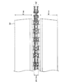
図2は、チップサイズパッケージ33をスキップビアホール11のビア底側の実装パッド34上に実装した状態を示す縦断面図である。この図2は、チップサイズパッケージを実装した8層構造の多層フレキシブルプリント配線板32を略実寸法の比率で示したものであり、一般的なチップサイズパッケージ厚みである1mm程度に対し、8層フレキシブルプリント配線板32の厚みは0.3mm程度である。これから、8層フレキシブルプリント配線板32の薄さが分かる。
FIG. 2 is a longitudinal sectional view showing a state in which the chip size package 33 is mounted on the mounting
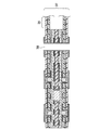
図3は、本発明の第2の実施例の構造を示した断面図である。この図3に示すように、ビルドアップ層16bを作製する際の一部抜きの箇所を変更することで、外層のケーブル部を第2導電層の回路35に単層で形成することが可能である。これにより、外層に単層ケーブルを有する8層フレキシブルプリント配線板37を得る。
FIG. 3 is a sectional view showing the structure of the second embodiment of the present invention. As shown in FIG. 3, it is possible to form the outer-layer cable portion as a single layer in the circuit 35 of the second conductive layer by changing the part of the build-
このようなケーブル構造とすることで、携帯電話のヒンジ部等の屈曲性を要求される部位へ好適に適用できる。また、図3のように貫通スルーホール38を組み合わせることで、全層を直接接続することも可能である。
By adopting such a cable structure, the present invention can be suitably applied to a portion requiring flexibility such as a hinge portion of a mobile phone. Moreover, it is also possible to connect all the layers directly by combining the through-through
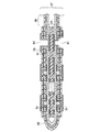
図4は、本発明の第3の実施例の構造を示した断面図である。この図4に示すように、ビルドアップ層の一部を残し、折り曲げた状態で積層することで、第3導電層3の回路39を反対面の第3導電層3’へ直接接続することもでき、第1導電層7に実装した部品の信号層となる第3導電層3の信号を効率的に反対面の第3導電層3’(反対面の信号層)へ接続可能である。
FIG. 4 is a cross-sectional view showing the structure of the third embodiment of the present invention. As shown in FIG. 4, the
また、4層を接続する層間接続として、ビアホール40(第1導電層7とコア基板21とを接続)、ステップビアホール41(第1導電層7’、第3導電層3’およびコア基板21を相互に接続)、ステップビアホール27(第1導電層7’、第2導電層2’、第3導電層3’およびコア基板21を相互に接続)、スキップビアホール28(第1導電層7とコア基板21とを接続)を形成可能で、外層から内層までの全ての層間導通をとることが可能である。
Further, as an interlayer connection for connecting the four layers, a via hole 40 (connecting the first
本発明による8層構造の多層フレキシブルプリント配線板は、第1導電層7,7’(CSP実装層)と第3導電層3,3’(信号層)とを位置合わせしていることから、第3導電層3,3’のランドを小径化でき、第2導電層2,2’にはグランド層を配置して電気特性を向上させることができる。
Since the multilayer flexible printed wiring board having the eight-layer structure according to the present invention aligns the first
また、この場合、ケーブルが第3導電層3,3’に配置可能であることから、最短距離で部品実装部を接続することができる。信号線が第2導電層2,2’にある場合には、ケーブルを第2導電層2,2’に配置することにも対応できる。第1導電層7,7’(CSP実装層)と第3導電層3,3’(信号層)とを接続するビアが狭ピッチに配置可能であることが必要であるが、スキップビア28(第1導電層7と第3導電層3とを接続)は70μmと小径であるため、ピッチ0.3mm以下に配置可能である。
In this case, since the cable can be arranged on the third
これらのことから、狭ピッチな高密度CSPを搭載可能な8層構造の多層フレキシブルプリント配線板を、コスト高なビアフィルめっきやその他の穴埋め工程を経ることなく、製造することが可能である。また、その他の要件についても、CSP実装パッドに貫通孔がなく、CSP実装可能な平坦性も十分確保している。 From these facts, it is possible to manufacture a multilayer flexible printed wiring board having an eight-layer structure capable of mounting a high-density CSP with a narrow pitch without going through costly via fill plating or other hole filling processes. As for other requirements, the CSP mounting pad does not have a through hole, and the flatness capable of CSP mounting is sufficiently secured.
さらに、3層構造のビルドアップ層を、コア基板とは別にカバーレイを形成する工程までロールトゥロールで連続的に流動可能であることから、自動化・少人化が可能で安価に生産可能である。 Furthermore, since the build-up layer with a three-layer structure can be continuously flowed by roll-to-roll until the process of forming the coverlay separately from the core substrate, it can be automated and reduced in number and can be produced at low cost. is there.
1 可撓性絶縁ベース材
2 銅箔
2a コンフォーマルマスク
2b 回路パターン
3 銅箔
3a,3b コンフォーマルマスク
3c 回路パターン
4 両面銅張積層板
5 配線基材
6 可撓性絶縁ベース材
7 銅箔
7a コンフォーマルマスク
8 片面銅張積層板
9 接着材
10 導通用孔
11 スキップビアホール
12 配線基材
13 ポリイミドフィルム
14 接着材
15 カバーレイ
16,16b ビルドアップ層
17 可撓性絶縁ベース材
18 スルーホール
19,21 回路パターン
21 両面コア基板
22 接着材
23 多層配線基材
24,25 導通用孔
26 導通用孔を有する多層配線基材
27 ステップビアホール(第1導電層と第2導電層と第3導電層とコア基板を接続)
28 スキップビアホール(第1導電層とコア基板を接続)
29 層間導通の完了した多層配線基材
30 外層のパターン
31 ケーブル部
32 ケーブル部を有する8層フレキシブルプリント配線板
33 チップサイズパッケージ
34 実装パッド
35 第2導電層のケーブル部
36 第3導電層のケーブル部
37 外層に単層ケーブルを有する8層構造の多層フレキシブルプリント配線板
38 貫通スルーホール
39 第3導電層の回路(反対側の第3導電層へ直接接続)
40 ビアホール(第1導電層とコア基板を接続)
41 ステップビアホール(第1導電層と第3導電層とコア基板を接続)
101 両面フレキシブルプリント配線板
102 両面フレキシブル配線基材
103 カバーレイ
104 接着材
105 6層の配線基材
106 接着材
107 片面フレキシブルプリント配線板
108 8層構造の多層フレキシブルプリント配線
DESCRIPTION OF
28 Skip via hole (connecting first conductive layer and core substrate)
29 Multilayer Wiring Substrate Completed with
40 via hole (connecting the first conductive layer and the core substrate)
41 step via hole (connecting first conductive layer, third conductive layer and core substrate)
DESCRIPTION OF
Claims (7)
前記ビルドアップ層の外層側から1層目の第1導電層には、チップサイズパッケージを実装する実装パッドを有し、
前記ビルドアップ層の外層側から2層目の第2導電層には、少なくとも前記チップサイズパッケージを搭載する領域の直下にグランド層を有し、
前記ビルドアップ層の外層側から3層目の第3導電層には、前記実装パッドから、第2導電層のグランド層をスキップするスキップビアホールを介して導通された、信号回路を引き回すための配線パターンを有し、
前記スキップビアホールが有底のブラインドビアホールであって、該ブラインドビアホールの底が第1導電層の前記実装パッドの裏面に接しているとともに、前記ビルドアップ層と前記コア基板とを導通するビアホールを前記スキップビアホールとは別に有し、
前記ビルドアップ層と一体化した可撓性ケーブル部を有する
ことを特徴とする多層フレキシブルプリント配線板。 In a multilayer flexible printed wiring board having a build-up layer having a three-layer structure on at least one side of a core substrate having a wiring pattern on both sides,
The first conductive layer from the outer layer side of the build-up layer has a mounting pad for mounting a chip size package,
The second conductive layer, which is the second layer from the outer layer side of the build-up layer, has a ground layer at least immediately below the region where the chip size package is mounted,
Wiring for routing a signal circuit, which is conducted from the mounting pad through a skip via hole that skips the ground layer of the second conductive layer, to the third conductive layer that is the third layer from the outer layer side of the buildup layer Has a pattern,
The skip via hole is a bottomed blind via hole, and the bottom of the blind via hole is in contact with the back surface of the mounting pad of the first conductive layer, and the via hole that conducts the build-up layer and the core substrate Apart from the skip beer hall,
A multilayer flexible printed wiring board comprising a flexible cable portion integrated with the build-up layer.
前記可撓性ケーブル部が、前記ビルドアップ層の第2導電層または第3導電層のみの単層ケーブルで構成されることを特徴とする、多層フレキシブルプリント配線板。 In the multilayer flexible printed wiring board according to claim 1,
The multilayer flexible printed wiring board, wherein the flexible cable portion is formed of a single-layer cable having only the second conductive layer or the third conductive layer of the buildup layer.
前記ビルドアップ層が前記コア基板の両面に折り曲げた状態で積層されてなり、前記ビルドアップ層間を接続する可撓性ケーブル部を有することを特徴とする、多層フレキシブルプリント配線板。 In the multilayer flexible printed wiring board according to claim 1 or 2,
A multilayer flexible printed wiring board comprising: a flexible cable portion that is formed by laminating the buildup layer on both sides of the core substrate and connecting the buildup layers.
a) 両面型の可撓性配線基材の一方の面における導通用孔の形成部位にレーザ加工用の開口を形成し、他方の面にグランド層及び導通用孔の形成部位の開口を含む配線パターンを形成する工程
b) 前記可撓性配線基材の配線パターンを形成した面と片面型の可撓性配線基材の可撓性絶縁ベース材側の面とを接着材を介して貼り合せ、3層構造の配線基材を形成する工程
c) 前記3層構造の配線基材の外層側から3層目の導電層となる第3導電層の導通用孔の形成部位の開口に対してレーザ加工を行い、外層側から1層目の導電層となる第1導電層まで達する有底の導通用孔を形成する工程
d) 前記導通用孔に対して導電化処理を行い、電解めっきによりブラインドビアホールを形成する工程
e) 前記第3導電層に配線パターンを形成する工程
f) 前記第3導電層の配線パターン上にカバーレイを形成する工程
g) 前記ビルドアップ層のカバーレイを形成した側を別途製作したコア基板側へ向け、前記コア基板に接着材を介し、積層する工程
h) 前記積層配線基材に対し、前記第1導電層の導通用孔形成部位から、コア基板まで達する導通用孔を形成する工程
i) 前記導通用孔に対し、導電化処理を行い電解めっきによりビアホールを形成する工程
をそなえたことを特徴とする多層フレキシブルプリント配線板の製造方法。 In the method for producing a multilayer flexible printed wiring board having a build-up layer having a three-layer structure on at least one side of a core substrate having a wiring pattern on both sides,
a) Wiring including an opening for laser processing in a portion where a conduction hole is formed on one surface of a double-sided flexible wiring substrate, and an opening where a ground layer and a conduction hole are formed on the other surface Pattern forming process
b) The surface of the flexible wiring substrate on which the wiring pattern is formed and the surface of the single-sided flexible wiring substrate on the side of the flexible insulating base material are bonded to each other with an adhesive. Process for forming wiring substrate
c) Laser processing is performed on the opening portion of the third conductive layer which is the third conductive layer from the outer layer side of the wiring substrate having the three-layer structure, and the first layer is formed from the outer layer side. A process of forming a bottomed conduction hole reaching the first conductive layer to be a conductive layer
d) Conducting the conductive holes and forming blind via holes by electrolytic plating
e) forming a wiring pattern on the third conductive layer
f) forming a coverlay on the wiring pattern of the third conductive layer
g) A step of laminating the side of the build-up layer on the core substrate facing the separately manufactured core substrate side through an adhesive.
h) A step of forming a conduction hole reaching the core substrate from the conduction hole forming portion of the first conductive layer with respect to the laminated wiring substrate.
i) A method for producing a multilayer flexible printed wiring board, comprising the step of conducting a conductive treatment for the conduction hole and forming a via hole by electrolytic plating.
前記e)工程が、
前記第3導電層に配線パターンを形成するとともに、前記第1導電層に導通用孔形成部位にレーザ加工用の開口を形成する工程を含み、
前記h)工程が、
前記積層配線基材に対し、前記第1導電層の導通用孔形成部位のレーザ加工用の開口をマスクとして、コア基板まで達する導通用孔をレーザ加工により形成する工程
であることを特徴とする多層フレキシブルプリント配線板の製造方法。 In the manufacturing method of the multilayer flexible printed wiring board of Claim 4,
Step e)
Forming a wiring pattern in the third conductive layer, and forming an opening for laser processing at a hole forming portion for conduction in the first conductive layer;
Step h)
A step of forming a hole for conduction reaching the core substrate by laser processing with respect to the laminated wiring substrate, using an opening for laser processing at a portion for forming a hole for conduction of the first conductive layer as a mask. A method for producing a multilayer flexible printed wiring board.
前記h)工程が、
前記積層配線基材に対し、前記第1導電層の導通用孔形成部位に、コア基板を含み全層を貫通する導通用孔をドリル加工により形成する工程
であることを特徴とする多層フレキシブルプリント配線板の製造方法。 In the manufacturing method of the multilayer flexible printed wiring board of Claim 4,
Step h)
A multilayer flexible print, comprising: forming a conductive hole including a core substrate and penetrating all layers in a conductive hole forming portion of the first conductive layer with respect to the laminated wiring substrate by a drilling process. A method for manufacturing a wiring board.
前記g)工程が、
前記ビルドアップ層のカバーレイを形成した側を別途製作したコア基板側へ向け、折り曲げた状態で、コア基板の両面に接着材を介して積層する工程
であることを特徴とする多層フレキシブルプリント配線板の製造方法。 In the manufacturing method of the multilayer flexible printed wiring board in any one of Claim 4 thru | or 6,
Step g)
Multilayer flexible printed wiring characterized in that it is a step of laminating the both sides of the core substrate with an adhesive in a folded state with the side of the buildup layer on which the coverlay is formed facing the separately manufactured core substrate side A manufacturing method of a board.
Priority Applications (3)
| Application Number | Priority Date | Filing Date | Title |
|---|---|---|---|
| JP2008110232A JP5259240B2 (en) | 2008-04-21 | 2008-04-21 | Multilayer flexible printed wiring board and manufacturing method thereof |
| TW098103413A TWI479972B (en) | 2008-04-21 | 2009-02-03 | Multi-layer flexible printed wiring board and manufacturing method thereof |
| CN200910132122.5A CN101568226B (en) | 2008-04-21 | 2009-04-21 | Multi-layer flexible printed circuit board and method of manufacturing the same |
Applications Claiming Priority (1)
| Application Number | Priority Date | Filing Date | Title |
|---|---|---|---|
| JP2008110232A JP5259240B2 (en) | 2008-04-21 | 2008-04-21 | Multilayer flexible printed wiring board and manufacturing method thereof |
Publications (2)
| Publication Number | Publication Date |
|---|---|
| JP2009260186A JP2009260186A (en) | 2009-11-05 |
| JP5259240B2 true JP5259240B2 (en) | 2013-08-07 |
Family
ID=41284089
Family Applications (1)
| Application Number | Title | Priority Date | Filing Date |
|---|---|---|---|
| JP2008110232A Active JP5259240B2 (en) | 2008-04-21 | 2008-04-21 | Multilayer flexible printed wiring board and manufacturing method thereof |
Country Status (3)
| Country | Link |
|---|---|
| JP (1) | JP5259240B2 (en) |
| CN (1) | CN101568226B (en) |
| TW (1) | TWI479972B (en) |
Families Citing this family (11)
| Publication number | Priority date | Publication date | Assignee | Title |
|---|---|---|---|---|
| WO2011096293A1 (en) * | 2010-02-08 | 2011-08-11 | 日本メクトロン株式会社 | Method of manufacturing multi-layered printed circuit board |
| CN102686052A (en) * | 2011-03-16 | 2012-09-19 | 钒创科技股份有限公司 | Flexible printed circuit board and its manufacturing method |
| CN103037625B (en) * | 2011-09-30 | 2016-01-13 | 无锡江南计算技术研究所 | With chip window printed substrate remove short-circuiting method |
| CN103052281A (en) * | 2011-10-14 | 2013-04-17 | 富葵精密组件(深圳)有限公司 | Embedded multilayer circuit board and manufacturing method thereof |
| CN103579008B (en) * | 2012-07-26 | 2017-11-10 | 中芯国际集成电路制造(上海)有限公司 | A kind of pad structure and preparation method thereof |
| CN104131278B (en) * | 2013-04-30 | 2016-08-10 | 富葵精密组件(深圳)有限公司 | Blackening potion and method for making circuit board |
| JP6240007B2 (en) * | 2014-03-18 | 2017-11-29 | 日本メクトロン株式会社 | Method for manufacturing flexible printed circuit board and intermediate product used for manufacturing flexible printed circuit board |
| CN106231788A (en) * | 2016-09-30 | 2016-12-14 | 深圳天珑无线科技有限公司 | Circuit board |
| JP6732723B2 (en) * | 2017-12-14 | 2020-07-29 | 日本メクトロン株式会社 | Printed wiring board for high frequency transmission |
| CN114430626B (en) * | 2020-10-29 | 2024-07-19 | 鹏鼎控股(深圳)股份有限公司 | Printed circuit board-to-printed circuit board connection structure and manufacturing method thereof |
| CN114698225B (en) * | 2020-12-31 | 2024-09-13 | 深南电路股份有限公司 | Battery protection plate, manufacturing method thereof and electronic device |
Family Cites Families (7)
| Publication number | Priority date | Publication date | Assignee | Title |
|---|---|---|---|---|
| US7256354B2 (en) * | 2000-06-19 | 2007-08-14 | Wyrzykowska Aneta O | Technique for reducing the number of layers in a multilayer circuit board |
| JP2002329966A (en) * | 2001-04-27 | 2002-11-15 | Sumitomo Bakelite Co Ltd | Wiring board for manufacturing multilayer wiring board, and multilayer wiring board |
| JP3879461B2 (en) * | 2001-09-05 | 2007-02-14 | 日立電線株式会社 | Wiring board and manufacturing method thereof |
| JP2006310543A (en) * | 2005-04-28 | 2006-11-09 | Ngk Spark Plug Co Ltd | Wiring board and its production process, wiring board with semiconductor circuit element |
| JP4527045B2 (en) * | 2005-11-01 | 2010-08-18 | 日本メクトロン株式会社 | Method for manufacturing multilayer wiring board having cable portion |
| TWI278268B (en) * | 2006-02-23 | 2007-04-01 | Via Tech Inc | Arrangement of non-signal through vias and wiring board applying the same |
| JP5095117B2 (en) * | 2006-04-12 | 2012-12-12 | 日本メクトロン株式会社 | Multilayer circuit board having cable portion and method for manufacturing the same |
-
2008
- 2008-04-21 JP JP2008110232A patent/JP5259240B2/en active Active
-
2009
- 2009-02-03 TW TW098103413A patent/TWI479972B/en active
- 2009-04-21 CN CN200910132122.5A patent/CN101568226B/en not_active Expired - Fee Related
Also Published As
| Publication number | Publication date |
|---|---|
| JP2009260186A (en) | 2009-11-05 |
| CN101568226A (en) | 2009-10-28 |
| TWI479972B (en) | 2015-04-01 |
| TW200945987A (en) | 2009-11-01 |
| CN101568226B (en) | 2012-07-11 |
Similar Documents
| Publication | Publication Date | Title |
|---|---|---|
| JP5259240B2 (en) | Multilayer flexible printed wiring board and manufacturing method thereof | |
| KR101014228B1 (en) | Flexible multilayer wiring board and manufacturing method thereof | |
| US6972382B2 (en) | Inverted microvia structure and method of manufacture | |
| JP4876272B2 (en) | Printed circuit board and manufacturing method thereof | |
| JP2009277916A (en) | Wiring board, manufacturing method thereof, and semiconductor package | |
| KR101103301B1 (en) | A build-up printed circuit board with odd-layer and Manufacturing method of the same | |
| KR101201940B1 (en) | Method for manufacturing multilayer wiring board having cable part | |
| US20120011716A1 (en) | Method of manufacturing printed circuit board including outmost fine circuit pattern | |
| US20040124003A1 (en) | Double-sided printed circuit board without via holes and method of fabricating the same | |
| TWI500366B (en) | Multilayer printed wiring board and manufacturing method thereof | |
| KR20080101762A (en) | Manufacturing method of multilayer printed wiring board and the wiring board | |
| JP2006165496A (en) | Parallel multi-layer printed board having inter-layer conductivity through via post | |
| US8546698B2 (en) | Wiring board and method for manufacturing the same | |
| JP4934444B2 (en) | Semiconductor device and manufacturing method thereof | |
| KR100536315B1 (en) | Semiconductor packaging substrate and manufacturing method thereof | |
| JP4319917B2 (en) | Manufacturing method of component built-in wiring board | |
| TWI511634B (en) | Method for manufacturing circuit board | |
| KR101109277B1 (en) | Manufacturing method of printed circuit board | |
| JP4813204B2 (en) | Multilayer circuit board manufacturing method | |
| KR100601476B1 (en) | Package substrate using metal core and manufacturing method thereof | |
| JP2007287721A (en) | Multilayer circuit board having cable portion and method for manufacturing the same | |
| JP5000742B2 (en) | Method for manufacturing multilayer wiring board having cable portion | |
| CN121752086A (en) | Packaging substrate and its preparation method, semiconductor package | |
| KR20170079542A (en) | Printed circuit board | |
| KR20130065216A (en) | Multi-layered printed circuit board and manufacturing metheod thereof |
Legal Events
| Date | Code | Title | Description |
|---|---|---|---|
| A621 | Written request for application examination |
Free format text: JAPANESE INTERMEDIATE CODE: A621 Effective date: 20110315 |
|
| A977 | Report on retrieval |
Free format text: JAPANESE INTERMEDIATE CODE: A971007 Effective date: 20120726 |
|
| A131 | Notification of reasons for refusal |
Free format text: JAPANESE INTERMEDIATE CODE: A131 Effective date: 20120731 |
|
| TRDD | Decision of grant or rejection written | ||
| A01 | Written decision to grant a patent or to grant a registration (utility model) |
Free format text: JAPANESE INTERMEDIATE CODE: A01 Effective date: 20130329 |
|
| A61 | First payment of annual fees (during grant procedure) |
Free format text: JAPANESE INTERMEDIATE CODE: A61 Effective date: 20130424 |
|
| FPAY | Renewal fee payment (event date is renewal date of database) |
Free format text: PAYMENT UNTIL: 20160502 Year of fee payment: 3 |
|
| R150 | Certificate of patent or registration of utility model |
Ref document number: 5259240 Country of ref document: JP Free format text: JAPANESE INTERMEDIATE CODE: R150 Free format text: JAPANESE INTERMEDIATE CODE: R150 |
|
| R250 | Receipt of annual fees |
Free format text: JAPANESE INTERMEDIATE CODE: R250 |
|
| R250 | Receipt of annual fees |
Free format text: JAPANESE INTERMEDIATE CODE: R250 |
|
| R250 | Receipt of annual fees |
Free format text: JAPANESE INTERMEDIATE CODE: R250 |
|
| R250 | Receipt of annual fees |
Free format text: JAPANESE INTERMEDIATE CODE: R250 |
|
| R250 | Receipt of annual fees |
Free format text: JAPANESE INTERMEDIATE CODE: R250 |
|
| R250 | Receipt of annual fees |
Free format text: JAPANESE INTERMEDIATE CODE: R250 |
|
| R250 | Receipt of annual fees |
Free format text: JAPANESE INTERMEDIATE CODE: R250 |
|
| R250 | Receipt of annual fees |
Free format text: JAPANESE INTERMEDIATE CODE: R250 |
|
| R250 | Receipt of annual fees |
Free format text: JAPANESE INTERMEDIATE CODE: R250 |
|
| R250 | Receipt of annual fees |
Free format text: JAPANESE INTERMEDIATE CODE: R250 |
|
| S533 | Written request for registration of change of name |
Free format text: JAPANESE INTERMEDIATE CODE: R313533 |
|
| R350 | Written notification of registration of transfer |
Free format text: JAPANESE INTERMEDIATE CODE: R350 |
|
| R250 | Receipt of annual fees |
Free format text: JAPANESE INTERMEDIATE CODE: R250 |