JP5252020B2 - ポンプの取付構造 - Google Patents
ポンプの取付構造 Download PDFInfo
- Publication number
- JP5252020B2 JP5252020B2 JP2011067924A JP2011067924A JP5252020B2 JP 5252020 B2 JP5252020 B2 JP 5252020B2 JP 2011067924 A JP2011067924 A JP 2011067924A JP 2011067924 A JP2011067924 A JP 2011067924A JP 5252020 B2 JP5252020 B2 JP 5252020B2
- Authority
- JP
- Japan
- Prior art keywords
- housing
- mounting
- insertion recess
- bolt
- pump
- Prior art date
- Legal status (The legal status is an assumption and is not a legal conclusion. Google has not performed a legal analysis and makes no representation as to the accuracy of the status listed.)
- Expired - Fee Related
Links
- 230000037431 insertion Effects 0.000 claims description 92
- 238000003780 insertion Methods 0.000 claims description 92
- 230000002093 peripheral effect Effects 0.000 claims description 29
- 239000010687 lubricating oil Substances 0.000 claims description 20
- 238000007789 sealing Methods 0.000 claims description 6
- 239000000446 fuel Substances 0.000 description 9
- XEEYBQQBJWHFJM-UHFFFAOYSA-N Iron Chemical compound [Fe] XEEYBQQBJWHFJM-UHFFFAOYSA-N 0.000 description 6
- 239000012530 fluid Substances 0.000 description 5
- UFHFLCQGNIYNRP-UHFFFAOYSA-N Hydrogen Chemical compound [H][H] UFHFLCQGNIYNRP-UHFFFAOYSA-N 0.000 description 3
- 239000001257 hydrogen Substances 0.000 description 3
- 229910052739 hydrogen Inorganic materials 0.000 description 3
- 229910052742 iron Inorganic materials 0.000 description 3
- 230000009466 transformation Effects 0.000 description 3
- XAGFODPZIPBFFR-UHFFFAOYSA-N aluminium Chemical compound [Al] XAGFODPZIPBFFR-UHFFFAOYSA-N 0.000 description 2
- 229910052782 aluminium Inorganic materials 0.000 description 2
- QVGXLLKOCUKJST-UHFFFAOYSA-N atomic oxygen Chemical compound [O] QVGXLLKOCUKJST-UHFFFAOYSA-N 0.000 description 2
- 238000006073 displacement reaction Methods 0.000 description 2
- 239000000314 lubricant Substances 0.000 description 2
- 239000001301 oxygen Substances 0.000 description 2
- 229910052760 oxygen Inorganic materials 0.000 description 2
- 230000000694 effects Effects 0.000 description 1
- 230000005489 elastic deformation Effects 0.000 description 1
- 238000010248 power generation Methods 0.000 description 1
- 230000001360 synchronised effect Effects 0.000 description 1
Images


Classifications
-
- F—MECHANICAL ENGINEERING; LIGHTING; HEATING; WEAPONS; BLASTING
- F01—MACHINES OR ENGINES IN GENERAL; ENGINE PLANTS IN GENERAL; STEAM ENGINES
- F01C—ROTARY-PISTON OR OSCILLATING-PISTON MACHINES OR ENGINES
- F01C21/00—Component parts, details or accessories not provided for in groups F01C1/00 - F01C20/00
- F01C21/007—General arrangements of parts; Frames and supporting elements
-
- F—MECHANICAL ENGINEERING; LIGHTING; HEATING; WEAPONS; BLASTING
- F01—MACHINES OR ENGINES IN GENERAL; ENGINE PLANTS IN GENERAL; STEAM ENGINES
- F01C—ROTARY-PISTON OR OSCILLATING-PISTON MACHINES OR ENGINES
- F01C21/00—Component parts, details or accessories not provided for in groups F01C1/00 - F01C20/00
- F01C21/10—Outer members for co-operation with rotary pistons; Casings
-
- F—MECHANICAL ENGINEERING; LIGHTING; HEATING; WEAPONS; BLASTING
- F04—POSITIVE - DISPLACEMENT MACHINES FOR LIQUIDS; PUMPS FOR LIQUIDS OR ELASTIC FLUIDS
- F04C—ROTARY-PISTON, OR OSCILLATING-PISTON, POSITIVE-DISPLACEMENT MACHINES FOR LIQUIDS; ROTARY-PISTON, OR OSCILLATING-PISTON, POSITIVE-DISPLACEMENT PUMPS
- F04C11/00—Combinations of two or more machines or pumps, each being of rotary-piston or oscillating-piston type; Pumping installations
- F04C11/008—Enclosed motor pump units
-
- F—MECHANICAL ENGINEERING; LIGHTING; HEATING; WEAPONS; BLASTING
- F16—ENGINEERING ELEMENTS AND UNITS; GENERAL MEASURES FOR PRODUCING AND MAINTAINING EFFECTIVE FUNCTIONING OF MACHINES OR INSTALLATIONS; THERMAL INSULATION IN GENERAL
- F16B—DEVICES FOR FASTENING OR SECURING CONSTRUCTIONAL ELEMENTS OR MACHINE PARTS TOGETHER, e.g. NAILS, BOLTS, CIRCLIPS, CLAMPS, CLIPS OR WEDGES; JOINTS OR JOINTING
- F16B39/00—Locking of screws, bolts or nuts
- F16B39/22—Locking of screws, bolts or nuts in which the locking takes place during screwing down or tightening
- F16B39/28—Locking of screws, bolts or nuts in which the locking takes place during screwing down or tightening by special members on, or shape of, the nut or bolt
- F16B39/284—Locking by means of elastic deformation
-
- F—MECHANICAL ENGINEERING; LIGHTING; HEATING; WEAPONS; BLASTING
- F04—POSITIVE - DISPLACEMENT MACHINES FOR LIQUIDS; PUMPS FOR LIQUIDS OR ELASTIC FLUIDS
- F04C—ROTARY-PISTON, OR OSCILLATING-PISTON, POSITIVE-DISPLACEMENT MACHINES FOR LIQUIDS; ROTARY-PISTON, OR OSCILLATING-PISTON, POSITIVE-DISPLACEMENT PUMPS
- F04C15/00—Component parts, details or accessories of machines, pumps or pumping installations, not provided for in groups F04C2/00 - F04C14/00
- F04C15/0003—Sealing arrangements in rotary-piston machines or pumps
- F04C15/0034—Sealing arrangements in rotary-piston machines or pumps for other than the working fluid, i.e. the sealing arrangements are not between working chambers of the machine
-
- F—MECHANICAL ENGINEERING; LIGHTING; HEATING; WEAPONS; BLASTING
- F04—POSITIVE - DISPLACEMENT MACHINES FOR LIQUIDS; PUMPS FOR LIQUIDS OR ELASTIC FLUIDS
- F04C—ROTARY-PISTON, OR OSCILLATING-PISTON, POSITIVE-DISPLACEMENT MACHINES FOR LIQUIDS; ROTARY-PISTON, OR OSCILLATING-PISTON, POSITIVE-DISPLACEMENT PUMPS
- F04C2/00—Rotary-piston machines or pumps
- F04C2/08—Rotary-piston machines or pumps of intermeshing-engagement type, i.e. with engagement of co-operating members similar to that of toothed gearing
- F04C2/12—Rotary-piston machines or pumps of intermeshing-engagement type, i.e. with engagement of co-operating members similar to that of toothed gearing of other than internal-axis type
-
- F—MECHANICAL ENGINEERING; LIGHTING; HEATING; WEAPONS; BLASTING
- F04—POSITIVE - DISPLACEMENT MACHINES FOR LIQUIDS; PUMPS FOR LIQUIDS OR ELASTIC FLUIDS
- F04C—ROTARY-PISTON, OR OSCILLATING-PISTON, POSITIVE-DISPLACEMENT MACHINES FOR LIQUIDS; ROTARY-PISTON, OR OSCILLATING-PISTON, POSITIVE-DISPLACEMENT PUMPS
- F04C2230/00—Manufacture
- F04C2230/60—Assembly methods
- F04C2230/604—Mounting devices for pumps or compressors
-
- F—MECHANICAL ENGINEERING; LIGHTING; HEATING; WEAPONS; BLASTING
- F04—POSITIVE - DISPLACEMENT MACHINES FOR LIQUIDS; PUMPS FOR LIQUIDS OR ELASTIC FLUIDS
- F04C—ROTARY-PISTON, OR OSCILLATING-PISTON, POSITIVE-DISPLACEMENT MACHINES FOR LIQUIDS; ROTARY-PISTON, OR OSCILLATING-PISTON, POSITIVE-DISPLACEMENT PUMPS
- F04C2240/00—Components
- F04C2240/80—Other components
- F04C2240/805—Fastening means, e.g. bolts
-
- F—MECHANICAL ENGINEERING; LIGHTING; HEATING; WEAPONS; BLASTING
- F04—POSITIVE - DISPLACEMENT MACHINES FOR LIQUIDS; PUMPS FOR LIQUIDS OR ELASTIC FLUIDS
- F04C—ROTARY-PISTON, OR OSCILLATING-PISTON, POSITIVE-DISPLACEMENT MACHINES FOR LIQUIDS; ROTARY-PISTON, OR OSCILLATING-PISTON, POSITIVE-DISPLACEMENT PUMPS
- F04C2270/00—Control; Monitoring or safety arrangements
- F04C2270/12—Vibration
-
- F—MECHANICAL ENGINEERING; LIGHTING; HEATING; WEAPONS; BLASTING
- F16—ENGINEERING ELEMENTS AND UNITS; GENERAL MEASURES FOR PRODUCING AND MAINTAINING EFFECTIVE FUNCTIONING OF MACHINES OR INSTALLATIONS; THERMAL INSULATION IN GENERAL
- F16B—DEVICES FOR FASTENING OR SECURING CONSTRUCTIONAL ELEMENTS OR MACHINE PARTS TOGETHER, e.g. NAILS, BOLTS, CIRCLIPS, CLAMPS, CLIPS OR WEDGES; JOINTS OR JOINTING
- F16B5/00—Joining sheets or plates, e.g. panels, to one another or to strips or bars parallel to them
- F16B5/02—Joining sheets or plates, e.g. panels, to one another or to strips or bars parallel to them by means of fastening members using screw-thread
- F16B5/0241—Joining sheets or plates, e.g. panels, to one another or to strips or bars parallel to them by means of fastening members using screw-thread with the possibility for the connection to absorb deformation, e.g. thermal or vibrational
Landscapes
- Engineering & Computer Science (AREA)
- General Engineering & Computer Science (AREA)
- Mechanical Engineering (AREA)
- Compressor (AREA)
- Applications Or Details Of Rotary Compressors (AREA)
- Details Of Reciprocating Pumps (AREA)
Description
例えば、燃料電池システムにおいて、燃料電池に酸素と水素を供給して発電させることで、この発電による発熱によりハウジングH及びボディBdは温度上昇し、この温度の上昇に伴い、ハウジングH及びボディBdが熱膨張する。ここで、ハウジングHとボディBdとの間には温度差が生じるとともに熱膨張係数も異なるため、ハウジングHの熱膨張とボディBdの熱膨張とは相対差が生じており、熱膨張したことによるハウジングHの変形量とボディBdの変形量とは異なっている。
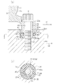
(1)第2〜第4取付脚部41b,41c,41dには挿通孔42を有する取付部43が設けられるとともに、取付部43は、被取付面Bd1の挿入凹部51に挿入されている。挿通孔42とボルトBとの間には第1隙間S1が形成され、取付部43と挿入凹部51との間には第2隙間S2が形成されており、挿入凹部51内には潤滑油60が充填されている。よって、熱膨張によりハウジングHの変形量とボディBdの変形量とに差が生じたとき、ボルトBは、第1隙間S1が設けられている分だけ、挿通孔42内において、ボディBdが熱膨張することに伴う移動が許容され、取付部43は、第1隙間S1及び第2隙間S2が設けられている分だけ挿入凹部51内での移動が許容される。したがって、ハウジングHとボディBdとの変形量に差異が生じても、ボルトBに負荷がかかってしまうことを抑制することができる。その結果、ハウジングHが変形してしまうことを抑制することができ、駆動軸21及び従動軸22を支持するベアリング23a,23b,23cが軸ずれしてしまうことを極力抑えることができる。
○ 実施形態では、ボディBdよりもハウジングHのほうが温度が高く、ハウジングHにおける第1取付脚部41aから離間する方向への変形量が、ボディBdにおける第1取付脚部41aから離間する方向への変形量よりも大きかったが、これに限らない。例えば、図4(a)及び(b)には、ボディBdよりもハウジングHのほうが温度が低く、ハウジングHにおける第1取付脚部41aから離間する方向(図4(a)において矢印X3で示す)への変形量が、ボディBdにおける第1取付脚部41aから離間する方向(図4(a)において矢印X4で示す)への変形量よりも小さい場合を示している。
○ 本発明を電動ルーツ型ポンプ10に具体化したが、これに限らず、その他のポンプ又は圧縮機(例えばスクロール式、スクリュー式、又はピストン式の圧縮機等)に具体化してもよい。
(イ)前記シール部材は、前記取付部に形成される溝部に取り付けられていることを特徴とする請求項1に記載のポンプの取付構造。
(ハ)前記ポンプは、燃料電池自動車に搭載される燃料電池システムを形成するボディに取り付けられていることを特徴とする請求項1及び前記技術的思想(イ)、(ロ)のいずれか一項に記載のポンプの取付構造。
Claims (1)
- 駆動源の駆動により回転する回転軸と、前記回転軸の回転に伴い駆動するポンプ部とがハウジング内に収容されるとともに、前記回転軸がベアリングを介して前記ハウジングに回転可能に支持され、前記ハウジングに設けられる複数の取付脚部にそれぞれ挿通されたボルトが被取付体に締結されることで前記被取付体に前記取付脚部が取り付けられるポンプの取付構造であって、
前記被取付体の被取付面に形成される挿入凹部に挿入される取付部を有する取付脚部が少なくとも一つ設けられるとともに、前記取付部には前記ボルトが挿通される挿通孔を有し、該挿通孔に挿通された前記ボルトが前記被取付体に締結されて前記挿入凹部の底面と前記取付部の底面とが摺動可能に接し、前記挿通孔の内周面と前記ボルトの外周面との間には第1隙間が形成され、前記取付部の外面と前記挿入凹部の内面との間には第2隙間が形成されており、前記挿入凹部内には潤滑油が充填されるとともに、前記第2隙間における前記潤滑油が充填されている領域よりも前記挿入凹部の開口側にはシール部材が配設されていて、前記第1隙間は、前記挿通孔に挿通された前記ボルトの頭部が前記取付部に当接することによって被覆され、前記ボルトの頭部と前記取付部との当接位置は、前記シール部材の配設位置よりも上方にあることを特徴とするポンプの取付構造。
Priority Applications (4)
| Application Number | Priority Date | Filing Date | Title |
|---|---|---|---|
| JP2011067924A JP5252020B2 (ja) | 2011-03-25 | 2011-03-25 | ポンプの取付構造 |
| US13/418,820 US20120244021A1 (en) | 2011-03-25 | 2012-03-13 | Pump mounting structure |
| CN201210073352.0A CN102691662B (zh) | 2011-03-25 | 2012-03-19 | 泵安装结构 |
| EP20120160078 EP2508709A3 (en) | 2011-03-25 | 2012-03-19 | Pump mounting structure |
Applications Claiming Priority (1)
| Application Number | Priority Date | Filing Date | Title |
|---|---|---|---|
| JP2011067924A JP5252020B2 (ja) | 2011-03-25 | 2011-03-25 | ポンプの取付構造 |
Publications (2)
| Publication Number | Publication Date |
|---|---|
| JP2012202305A JP2012202305A (ja) | 2012-10-22 |
| JP5252020B2 true JP5252020B2 (ja) | 2013-07-31 |
Family
ID=45936821
Family Applications (1)
| Application Number | Title | Priority Date | Filing Date |
|---|---|---|---|
| JP2011067924A Expired - Fee Related JP5252020B2 (ja) | 2011-03-25 | 2011-03-25 | ポンプの取付構造 |
Country Status (4)
| Country | Link |
|---|---|
| US (1) | US20120244021A1 (ja) |
| EP (1) | EP2508709A3 (ja) |
| JP (1) | JP5252020B2 (ja) |
| CN (1) | CN102691662B (ja) |
Families Citing this family (5)
| Publication number | Priority date | Publication date | Assignee | Title |
|---|---|---|---|---|
| US9927032B2 (en) | 2014-11-14 | 2018-03-27 | T & E Pumps, Ltd. | Direct drive assembly for pump assembly |
| JP2018201277A (ja) * | 2017-05-25 | 2018-12-20 | トヨタ自動車株式会社 | 車両用電動機格納装置 |
| DE102019100589A1 (de) * | 2019-01-11 | 2020-07-16 | The Bricks Groupe Llc | Pumpenvorrichtung insbesondere für mobile Verkehrsmittel |
| JP7159086B2 (ja) * | 2019-03-12 | 2022-10-24 | ジーエムシーシー アンド ウェリング アプライアンス コンポーネント (タイランド) カンパニー リミテッド | 圧縮機及びこれを備える機器 |
| CN110307156A (zh) * | 2019-07-15 | 2019-10-08 | 烟台菱辰能源有限公司 | 一种氢气循环泵及电机总成 |
Family Cites Families (12)
| Publication number | Priority date | Publication date | Assignee | Title |
|---|---|---|---|---|
| US2130827A (en) * | 1937-01-14 | 1938-09-20 | Clare L Brackett | Lock nut |
| JPH01182585A (ja) * | 1988-01-13 | 1989-07-20 | Komatsu Ltd | プラスチック製ギヤポンプ |
| DE9003770U1 (ja) * | 1990-03-31 | 1990-06-13 | Knf Neuberger Gmbh, 7800 Freiburg, De | |
| JP3046502B2 (ja) * | 1994-08-19 | 2000-05-29 | 矢崎総業株式会社 | ねじ締め式コネクタ |
| JP2921437B2 (ja) * | 1995-04-12 | 1999-07-19 | トヨタ自動車株式会社 | 締結構造 |
| DE19926585B4 (de) * | 1999-06-11 | 2005-07-07 | Deutsches Zentrum für Luft- und Raumfahrt e.V. | Konstruktionselement in Hybridbauweise |
| JP2004360652A (ja) * | 2003-06-06 | 2004-12-24 | Toyota Industries Corp | ルーツ式圧縮機モジュール |
| JP4462430B2 (ja) * | 2005-05-31 | 2010-05-12 | 株式会社不二越 | ポンプユニット |
| JP2007327478A (ja) * | 2006-06-09 | 2007-12-20 | Toyota Motor Corp | オイルポンプ |
| DE202007011491U1 (de) * | 2007-08-16 | 2007-10-18 | Acument Gmbh & Co. Ohg | Vorrichtung zur Befestigung von Kunststoffteilen an einer Kraftfahrzeugkarosserie |
| JP5018450B2 (ja) * | 2007-12-18 | 2012-09-05 | 株式会社豊田自動織機 | 電動圧縮機 |
| US8281603B2 (en) * | 2008-08-11 | 2012-10-09 | United Technologies Corporation | Fastener assembly for connecting rocket engine nozzles |
-
2011
- 2011-03-25 JP JP2011067924A patent/JP5252020B2/ja not_active Expired - Fee Related
-
2012
- 2012-03-13 US US13/418,820 patent/US20120244021A1/en not_active Abandoned
- 2012-03-19 EP EP20120160078 patent/EP2508709A3/en not_active Withdrawn
- 2012-03-19 CN CN201210073352.0A patent/CN102691662B/zh not_active Expired - Fee Related
Also Published As
| Publication number | Publication date |
|---|---|
| CN102691662B (zh) | 2014-12-31 |
| US20120244021A1 (en) | 2012-09-27 |
| JP2012202305A (ja) | 2012-10-22 |
| EP2508709A2 (en) | 2012-10-10 |
| EP2508709A3 (en) | 2014-01-01 |
| CN102691662A (zh) | 2012-09-26 |
Similar Documents
| Publication | Publication Date | Title |
|---|---|---|
| JP5252020B2 (ja) | ポンプの取付構造 | |
| JP4918936B2 (ja) | 電動ポンプ | |
| WO2010109875A1 (ja) | 流体機械 | |
| JP5622033B2 (ja) | 流体ポンプ | |
| JP5502008B2 (ja) | 内接歯車ポンプ | |
| JP5085528B2 (ja) | 回転ピストン機械 | |
| JP2015048872A (ja) | 車輪駆動装置 | |
| JP4935814B2 (ja) | 流体機械 | |
| JP2016053366A (ja) | 内接型ギヤポンプ | |
| CN105416031A (zh) | 车辆用驱动装置 | |
| JPWO2010013351A1 (ja) | スクロール流体機械 | |
| JP6105280B2 (ja) | 電動オイルポンプ | |
| JP4818378B2 (ja) | 電液一体型液圧装置 | |
| JP2010007516A (ja) | 電動オイルポンプ | |
| JP5803183B2 (ja) | ポンプおよび電動ポンプユニット | |
| JP2010242663A (ja) | スクリュー圧縮機 | |
| JP2016038086A (ja) | 車輪駆動装置 | |
| JP5637035B2 (ja) | ポンプ | |
| JP2014501866A (ja) | 流体装置用のバランスプレートアセンブリ | |
| JP2010144576A (ja) | 電動ルーツ型圧縮機 | |
| JP2016217162A (ja) | 燃料ポンプ | |
| JP2013072370A (ja) | オイルポンプ装置 | |
| JP5182197B2 (ja) | タービン発電機 | |
| WO2024060500A1 (zh) | 油泵装置和车辆 | |
| JP2011231687A (ja) | スクロール圧縮機 |
Legal Events
| Date | Code | Title | Description |
|---|---|---|---|
| A977 | Report on retrieval |
Free format text: JAPANESE INTERMEDIATE CODE: A971007 Effective date: 20121214 |
|
| A131 | Notification of reasons for refusal |
Free format text: JAPANESE INTERMEDIATE CODE: A131 Effective date: 20121225 |
|
| A521 | Request for written amendment filed |
Free format text: JAPANESE INTERMEDIATE CODE: A523 Effective date: 20130225 |
|
| TRDD | Decision of grant or rejection written | ||
| A01 | Written decision to grant a patent or to grant a registration (utility model) |
Free format text: JAPANESE INTERMEDIATE CODE: A01 Effective date: 20130319 |
|
| A61 | First payment of annual fees (during grant procedure) |
Free format text: JAPANESE INTERMEDIATE CODE: A61 Effective date: 20130401 |
|
| FPAY | Renewal fee payment (event date is renewal date of database) |
Free format text: PAYMENT UNTIL: 20160426 Year of fee payment: 3 |
|
| LAPS | Cancellation because of no payment of annual fees |