JP5247153B2 - Method for separating a mold from a solidified layer disposed on a substrate - Google Patents
Method for separating a mold from a solidified layer disposed on a substrate Download PDFInfo
- Publication number
- JP5247153B2 JP5247153B2 JP2007553123A JP2007553123A JP5247153B2 JP 5247153 B2 JP5247153 B2 JP 5247153B2 JP 2007553123 A JP2007553123 A JP 2007553123A JP 2007553123 A JP2007553123 A JP 2007553123A JP 5247153 B2 JP5247153 B2 JP 5247153B2
- Authority
- JP
- Japan
- Prior art keywords
- substrate
- force
- template
- region
- separation
- Prior art date
- Legal status (The legal status is an assumption and is not a legal conclusion. Google has not performed a legal analysis and makes no representation as to the accuracy of the status listed.)
- Active
Links
- 239000000758 substrate Substances 0.000 title claims description 84
- 238000000034 method Methods 0.000 title claims description 24
- 238000000926 separation method Methods 0.000 claims description 67
- 238000003825 pressing Methods 0.000 claims description 9
- 238000001459 lithography Methods 0.000 claims description 8
- 238000000465 moulding Methods 0.000 claims 3
- 238000005452 bending Methods 0.000 description 47
- 239000012530 fluid Substances 0.000 description 22
- 239000000463 material Substances 0.000 description 13
- 238000004891 communication Methods 0.000 description 10
- 230000008859 change Effects 0.000 description 7
- 238000004519 manufacturing process Methods 0.000 description 6
- 230000008569 process Effects 0.000 description 6
- 238000007789 sealing Methods 0.000 description 6
- 239000006227 byproduct Substances 0.000 description 5
- 238000012545 processing Methods 0.000 description 4
- VYPSYNLAJGMNEJ-UHFFFAOYSA-N Silicium dioxide Chemical compound O=[Si]=O VYPSYNLAJGMNEJ-UHFFFAOYSA-N 0.000 description 3
- 230000000694 effects Effects 0.000 description 3
- 239000007788 liquid Substances 0.000 description 3
- 230000004044 response Effects 0.000 description 3
- 230000015572 biosynthetic process Effects 0.000 description 2
- 230000001627 detrimental effect Effects 0.000 description 2
- 238000005516 engineering process Methods 0.000 description 2
- 239000007789 gas Substances 0.000 description 2
- 230000001788 irregular Effects 0.000 description 2
- 230000005855 radiation Effects 0.000 description 2
- IJGRMHOSHXDMSA-UHFFFAOYSA-N Atomic nitrogen Chemical compound N#N IJGRMHOSHXDMSA-UHFFFAOYSA-N 0.000 description 1
- 229910052782 aluminium Inorganic materials 0.000 description 1
- XAGFODPZIPBFFR-UHFFFAOYSA-N aluminium Chemical compound [Al] XAGFODPZIPBFFR-UHFFFAOYSA-N 0.000 description 1
- 238000013459 approach Methods 0.000 description 1
- 150000001875 compounds Chemical class 0.000 description 1
- 238000004132 cross linking Methods 0.000 description 1
- 230000007123 defense Effects 0.000 description 1
- 238000011161 development Methods 0.000 description 1
- 239000001307 helium Substances 0.000 description 1
- 229910052734 helium Inorganic materials 0.000 description 1
- SWQJXJOGLNCZEY-UHFFFAOYSA-N helium atom Chemical compound [He] SWQJXJOGLNCZEY-UHFFFAOYSA-N 0.000 description 1
- 230000007246 mechanism Effects 0.000 description 1
- 229910052751 metal Inorganic materials 0.000 description 1
- 239000002184 metal Substances 0.000 description 1
- 239000000203 mixture Substances 0.000 description 1
- 238000012986 modification Methods 0.000 description 1
- 230000004048 modification Effects 0.000 description 1
- 230000003287 optical effect Effects 0.000 description 1
- 238000000059 patterning Methods 0.000 description 1
- 238000005381 potential energy Methods 0.000 description 1
- 230000009467 reduction Effects 0.000 description 1
- 238000011160 research Methods 0.000 description 1
- 238000012827 research and development Methods 0.000 description 1
- 239000004065 semiconductor Substances 0.000 description 1
- 229910052710 silicon Inorganic materials 0.000 description 1
- 239000010703 silicon Substances 0.000 description 1
- 238000007711 solidification Methods 0.000 description 1
- 230000008023 solidification Effects 0.000 description 1
- 229910001220 stainless steel Inorganic materials 0.000 description 1
- 239000010935 stainless steel Substances 0.000 description 1
- 238000013518 transcription Methods 0.000 description 1
- 230000035897 transcription Effects 0.000 description 1
Images


Classifications
-
- H—ELECTRICITY
- H01—ELECTRIC ELEMENTS
- H01L—SEMICONDUCTOR DEVICES NOT COVERED BY CLASS H10
- H01L21/00—Processes or apparatus adapted for the manufacture or treatment of semiconductor or solid state devices or of parts thereof
- H01L21/67—Apparatus specially adapted for handling semiconductor or electric solid state devices during manufacture or treatment thereof; Apparatus specially adapted for handling wafers during manufacture or treatment of semiconductor or electric solid state devices or components ; Apparatus not specifically provided for elsewhere
- H01L21/683—Apparatus specially adapted for handling semiconductor or electric solid state devices during manufacture or treatment thereof; Apparatus specially adapted for handling wafers during manufacture or treatment of semiconductor or electric solid state devices or components ; Apparatus not specifically provided for elsewhere for supporting or gripping
- H01L21/6831—Apparatus specially adapted for handling semiconductor or electric solid state devices during manufacture or treatment thereof; Apparatus specially adapted for handling wafers during manufacture or treatment of semiconductor or electric solid state devices or components ; Apparatus not specifically provided for elsewhere for supporting or gripping using electrostatic chucks
-
- H—ELECTRICITY
- H01—ELECTRIC ELEMENTS
- H01L—SEMICONDUCTOR DEVICES NOT COVERED BY CLASS H10
- H01L21/00—Processes or apparatus adapted for the manufacture or treatment of semiconductor or solid state devices or of parts thereof
- H01L21/67—Apparatus specially adapted for handling semiconductor or electric solid state devices during manufacture or treatment thereof; Apparatus specially adapted for handling wafers during manufacture or treatment of semiconductor or electric solid state devices or components ; Apparatus not specifically provided for elsewhere
- H01L21/683—Apparatus specially adapted for handling semiconductor or electric solid state devices during manufacture or treatment thereof; Apparatus specially adapted for handling wafers during manufacture or treatment of semiconductor or electric solid state devices or components ; Apparatus not specifically provided for elsewhere for supporting or gripping
- H01L21/6838—Apparatus specially adapted for handling semiconductor or electric solid state devices during manufacture or treatment thereof; Apparatus specially adapted for handling wafers during manufacture or treatment of semiconductor or electric solid state devices or components ; Apparatus not specifically provided for elsewhere for supporting or gripping with gripping and holding devices using a vacuum; Bernoulli devices
-
- Y—GENERAL TAGGING OF NEW TECHNOLOGICAL DEVELOPMENTS; GENERAL TAGGING OF CROSS-SECTIONAL TECHNOLOGIES SPANNING OVER SEVERAL SECTIONS OF THE IPC; TECHNICAL SUBJECTS COVERED BY FORMER USPC CROSS-REFERENCE ART COLLECTIONS [XRACs] AND DIGESTS
- Y10—TECHNICAL SUBJECTS COVERED BY FORMER USPC
- Y10T—TECHNICAL SUBJECTS COVERED BY FORMER US CLASSIFICATION
- Y10T29/00—Metal working
- Y10T29/49—Method of mechanical manufacture
- Y10T29/49764—Method of mechanical manufacture with testing or indicating
- Y10T29/49778—Method of mechanical manufacture with testing or indicating with aligning, guiding, or instruction
- Y10T29/4978—Assisting assembly or disassembly
-
- Y—GENERAL TAGGING OF NEW TECHNOLOGICAL DEVELOPMENTS; GENERAL TAGGING OF CROSS-SECTIONAL TECHNOLOGIES SPANNING OVER SEVERAL SECTIONS OF THE IPC; TECHNICAL SUBJECTS COVERED BY FORMER USPC CROSS-REFERENCE ART COLLECTIONS [XRACs] AND DIGESTS
- Y10—TECHNICAL SUBJECTS COVERED BY FORMER USPC
- Y10T—TECHNICAL SUBJECTS COVERED BY FORMER US CLASSIFICATION
- Y10T29/00—Metal working
- Y10T29/49—Method of mechanical manufacture
- Y10T29/49998—Work holding
Description
(関連特許出願の相互引用)
本出願は、出願全体が本願明細書に組入れられる2005年1月31日に提出され、発明者としてDaniel A.Babbs、Byung−Jin ChoiおよびAnshuman Cheralaが掲載された「CHUCKING SYSTEM FOR NANO−MANUFACTURING」という表題の米国特許出願公開第11/047428号の分割特許出願であり、2005年1月31日に提出され、発明者としてByung−Jin Choi、Anshuman CheralaおよびDaniel A.Babbsが掲載された「METHOD OF RETAINING A SUBSTRATE TO A WAFER CHUCK」という表題の米国特許出願公開第11/047428号の分割である。
(Mutual citation of related patent applications)
This application was filed on Jan. 31, 2005, the entire application of which is incorporated herein by reference, and Daniel Ind. US Patent Application Publication No. 11/047428 entitled “CHUCKING SYSTEM FOR NANO-MANUFACTURING” published by Babbs, Byung-Jin Choi and Anshuman Cherala, filed on January 31, 2005, As inventors, Byung-Jin Choi, Anshuman Chelara and Daniel A. This is a division of US Patent Application Publication No. 11/047428 entitled “METHOD OF RETAINING A SUBSTRATE TO A WAFER CHUCK” published by Babbs.
(連邦政府による資金提供を受けた研究開発の記載)
米国政府が本発明の一括払いライセンス、および米国国防総省国防高等研究事業局(DARPA)によって与えられるN66001−01−1−8964とN66001−02−C−8011の条件で提供されるような妥当な条件で他者にライセンスを与えるように特許所有者に要求する権利を限られた状況の中で有する。
(Description of research and development funded by the federal government)
Reasonable conditions as provided by the US Government under the lump sum license of the present invention and the conditions of N66001-01-1-8964 and N66001-02-C-8011 awarded by the Department of Defense Advanced Research Projects Agency (DARPA) In limited circumstances, they have the right to require patent owners to license others.
本発明の分野は概して構造体のナノ加工に関する。さらに特定すると、本発明はインプリント・リソグラフィ工程において基板上に配置された固化層からテンプレートを分離させる方法に向けられる。ナノ加工は極めて小さい構造体、例えばナノメートル以下のオーダーの外観を有する構造体の加工を含む。ナノ加工が大きな影響を与えた1つの分野は集積回路の処理にある。半導体処理工業は基板上の単位面積当たりの回路を増やす一方で、さらに大きな生産収率を得るために努力を続けているため、ナノ加工はますます重要になる。ナノ加工は形成される構造体の最小外観寸法のさらなる減少を可能にする一方でさらに大きな処理制御を提供する。ナノ加工が使用されてきた他の開発の分野はバイオテクノロジー、光技術、機械系などを含む。 The field of the invention relates generally to nanofabrication of structures. More particularly, the present invention is directed to a method for separating a template from a solidified layer disposed on a substrate in an imprint lithography process. Nanofabrication includes the fabrication of very small structures, such as structures having an appearance on the order of nanometers or less. One area where nanofabrication has had a major impact is in the processing of integrated circuits. Nanofabrication becomes increasingly important as the semiconductor processing industry continues to strive for higher production yields while increasing the circuits per unit area on the substrate. Nanofabrication provides greater processing control while allowing further reduction of the minimum appearance dimensions of the formed structure. Other areas of development where nanofabrication has been used include biotechnology, optical technology, mechanical systems, and the like.
ナノ加工技術の一例は一般的にインプリント・リソグラフィと称される。例となるインプリント・リソグラフィは米国特許出願公開第10/264960号として出願された「Method and a Mold to Arrange Features on aSubstrate to Replicate Features having Minimal Dimensional Variability」という表題の米国公開特許出願番号2004/0065976、米国特許出願公開第10/264926号として出願された「Method of Forming a Layer on a Substrate to Facilitate Fabrication of Metrology Standards」という表題の米国公開特許出願番号2004/0065252、米国特許出願公開第10/235314号として出願された「Functional Patterning Material for Imprint Lithography Processes」という表題の米国公開特許出願番号2004/0046271などの多くの公報に詳しく述べられており、これらのすべては本発明の譲受人に譲渡される。 An example of nanofabrication technology is commonly referred to as imprint lithography. An exemplary imprint lithography is "Method and a Mold to Arrange Features on a Substrate to Replicate Featuring Haven Minimal Dimension US Patent Publication No. 6 / US Patent Application No. 10/264960". US Patent Application Publication No. 2004/0065252, entitled “Method of Forming a Layer on a Substrated to Facility Fabrication of Metrology Standards,” filed as US Patent Application Publication No. 10/264926, United States Patent Application Publication No. 2004/0065252, entitled “Method of Forming a Layer on a Substituting to Facility Fabrication of Metrology Standards”. It is described in detail in many publications such as US Published Patent Application No. 2004/0046271 entitled “Functional Patterning Material for Imprint Lithography Processes” filed as 10/235314, all of which are assigned to the present invention. Assigned to.
前述の米国公開特許出願の各々に開示された基本的なインプリント・リソグラフィ技術は重合可能な層の中へのレリーフ・パターンの形成と、その下側の基板へのレリーフ・パターンに対応するパターンの転写を含む。この目的のために、基板から間隔を置いてテンプレートが使用され、成形可能な液体がテンプレートと基板の間でこれらと接触して存在する。この液体が固化させられて固化層を形成する。固化層は、その液体と接触しているテンプレートの面の形状に一致する記録されたパターンを有する。このテンプレートが固化層から分離され、それにより、テンプレートと基板は隔てられる。次いで基板と固化層は、固化層内のパターンに対応するレリーフの像を基板内に転写するための処理を受ける。固化層からテンプレートを分離させる際に、記録されたパターンが損傷を受けることがある。 The basic imprint lithography technique disclosed in each of the aforementioned U.S. published patent applications involves the formation of a relief pattern in the polymerizable layer and a pattern corresponding to the relief pattern on the underlying substrate. Including transcription. For this purpose, a template is used at a distance from the substrate, and a moldable liquid exists between and in contact with the template and the substrate. This liquid is solidified to form a solidified layer. The solidified layer has a recorded pattern that matches the shape of the surface of the template that is in contact with the liquid. This template is separated from the solidified layer, thereby separating the template and the substrate. The substrate and solidified layer are then subjected to a process for transferring a relief image corresponding to the pattern in the solidified layer into the substrate. When separating the template from the solidified layer, the recorded pattern may be damaged.
記録されたパターンへの損傷を最小限にする改善された分離技術を提供することが望まれる。 It would be desirable to provide an improved separation technique that minimizes damage to the recorded pattern.
本発明はテンプレート内に含まれるモールドを基板上に配置された層から分離させる方法に向けられる。この方法はとりわけ、層からテンプレートを分離させるためにテンプレートに分離強制力を印加する工程、および分離を行うために必要とされる分離強制力を小さくするために基板を局所的に変形させる工程を含む。分離強制力を小さくすることによって、記録された層への損傷が最小限にされる。これらの実施形態その他は以下でさらに十分に述べられる。 The present invention is directed to a method of separating a mold contained in a template from a layer disposed on a substrate. This method includes, inter alia, applying a separation force to the template to separate the template from the layer, and locally deforming the substrate to reduce the separation force required to perform the separation. Including. By reducing the separation force, damage to the recorded layer is minimized. These embodiments and others are described more fully below.
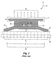
図1を参照すると、テンプレート10がインプリンティング層12と接触して示されている。通常では、テンプレート10は石英ガラスで構成され、インプリンティング層12は当該技術で知られているいずれかの材料から形成されている。インプリンティング材料12に関して例となる組成は、2003年1月24日に提出され、本願明細書に参照で組入れる「Materials and Methods for Imprint Lithography」という表題の米国特許出願公開第10/763885号明細書に開示されている。インプリンティング層12は基板14上に配置され、基板14は厚さ「t」を有する。基板14はシリコン、石英ガラス、金属、または集積回路の製造に通常関連する化合物材料を含めた事実上いずれの材料から形成されてもよい。テンプレート10はその上に配置された複数の特徴構造を有する面16を含み、これら複数の特徴構造は複数の凸部18と凹部20を含む。複数の凸部18と凹部20はインプリンティング層12へと転写されるべきパターンを形成し、レリーフの像を形成する。より具体的には、インプリンティング層12の材料が複数の凹部20内に進入してこれを充填することでテンプレート10の面16全域にわたって隣接する構造を備えたインプリンティング層12を形成するように、テンプレート10がインプリンティング層12に接触する。通常ではテンプレート10とインプリンティング層12を取り巻く雰囲気はヘリウムなどの気体で満たされている。テンプレート10はインプリント・ヘッド11に接続されている。インプリント・ヘッド11はX、Y、および/またはZ軸に沿って動くように構成され、Z軸に沿って基板14から離れる方向にテンプレート10を移動させることによって分離強制力FSを発生させることができる。この目的のために、基板14は通常ではZ軸に対して定位置に留まり、その一方でインプリント・ヘッド11が移動させられる。
Referring to FIG. 1, a
インプリンティング層12は、化学線作用成分に晒されると重合され、架橋させられて固化物質を形成するように光電性材料から形成される。この化学線作用成分は紫外波長、熱エネルギー、電磁エネルギー、可視光などを含む。使用されるこの化学線作用成分は当業者によく知られており、通常ではインプリンティング層12が形成される材料によって決まる。
The
インプリンティング層12の固化は、テンプレート10がこれと接触し、インプリンティング層12が複数の凹部20を充填した後に起こる。その後、テンプレート10がインプリンティング層12から分離される。この方式で、テンプレート10のパターンに対応するパターンでレリーフの像がインプリンティング層12へと記録される。
Solidification of the
固化インプリンティング層12からのテンプレート10の分離はテンプレート10への力FSの適用によって行われる。分離強制力FSはテンプレート10とインプリンティング層12の間の接着力、および曲げ(変形)に対する基板14の抵抗に打ち勝つのに十分な大きさである。基板14の一部の変形は固化インプリンティング層12からのテンプレート10の分離を促すと考えられる。いずれかのよく知られている曲げ力FC、例えば電磁力、磁力、真空力などを使用した分離の際にウェハ・チャック22が基板14を保持する。結果として、分離強制力FSの方向は通常では曲げ力FCの方向と反対である。通常、ウェハ・チャック22はX、Y、および/またはZ軸に沿って移動する試料台23によって支えられる。一例のインプリント・リソグラフィ・システムは商品名IMPRIO(商標)100で販売されており、Molecular Imprints,Inc.,Austin,Texasから入手可能である。
Separation of the
図1に示されるように、基板14の曲げ(変形)の程度は加えられる分離強制力FSの関数であり、通常では、基板14が距離dでウェハ・チャック22から隙間を開けられる曲げ領域24の形成に結果としてつながる。曲げ領域24は通常ではテンプレート10と接触したインプリンティング層12の領域の付近に生成され、処理領域と称される。
As shown in FIG. 1, the degree of bending (deformation) of the
しかしながら、テンプレート10と固化インプリンティング層12の分離を行うために必要な分離強制力FSの大きさを最小にすることが望ましい。例えば、分離強制力FSの大きさの最小化は、テンプレート10と基板14が適切に位置合わせされることを可能にし、同様にテンプレートのパターン面積対全テンプレート面積の増大した比を可能にするように位置合わせ工程を容易にする。付け加えると、テンプレート10と固化インプリンティング層12の分離を行うために必要な分離強制力FSの最小化はテンプレート10、基板14、固化インプリンティング材料12から成る構造の変化が起こるのを小さくする。
However, it is desirable to minimize the magnitude of the separation forcing force F S necessary for separating the
さらに、基板14の変形は曲げ領域24内にポテンシャル・エネルギーを生成し、これは固化インプリンティング層12からテンプレート10の分離の際の運動エネルギーへ変換される。特に、固化インプリンティング層12からのテンプレート10の分離の後、基板14への分離強制力FSはゼロに近くなる。曲げ力FCと、基板14が形成される材料の弾性は、曲げ領域24がチャック22に向かって加速させる原因となり、それにより、曲げ領域24は通常ではウェハ・チャック22と衝突する。ウェハ・チャック22と曲げ領域24の衝突は基板14とその上に形成される固化インプリンティング層12の構造的完全性を危うくする有害な影響を有する。これは、中でも基板14とテンプレート10の間の位置合わせに問題を生じさせる。
Further, the deformation of the
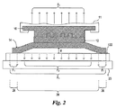
図2を参照すると、本発明は固化インプリンティング層12からのテンプレート10の分離に関連する前述の有害な影響をたとえ阻止しないとしても少なくする。これは、所定の基板14、テンプレート10、固化インプリンティング層12に関してテンプレート10と固化インプリンティング層12の間の分離を行うために必要な分離強制力FSの大きさを小さくすることによって達成される。この目的のために、ウェハ・チャック122は特に分離の際に基板14が受ける曲げ(変形)の程度を制御するように構成される。ウェハ・チャック122は、複数の独立して生成される力F1とF2から曲げ力FCを生成させる。これは基板14全域にわたって方向と大きさで変わることが可能な曲げ力を与える。例えば、可変の力F2の大きさはチャッキング力F1より大幅に小さいことが可能である。結果として、テンプレート10が分離強制力FSを受けると、チャッキング力F1は基板14の非曲げ領域26に関連し、可変の力F2は基板14の曲げ領域24に関連する。
Referring to FIG. 2, the present invention reduces, if not inhibits, the aforementioned detrimental effects associated with the separation of the
この例では、力F1とF2は両方共に分離強制力FSの方向と実質的に反対の方向に沿っている。分離強制力FSは図1に関連して上記で検討されたように、テンプレートが接続されるインプリンティング・ヘッド11の移動によって生成される。付け加えると、図2に示されるウェハ・チャック122は図1に関連して上記で検討されたように試料台23によって支えられている。しかしながら、テンプレート10の位置をZ軸に対して固定して保ち、試料台23を使用して基板14をZ軸に沿ってテンプレート10から離れる方向に移動させることによって分離強制力FSが生成されてもよいことは留意されるべきである。場合によっては、分離強制力FSはZ軸に沿って反対方向に移動するテンプレート10と基板14の組合せから結果として生じてもよい。しかしながらこの検討の目的に関すると、本発明は基板がX軸に対して固定して保持される一方、テンプレート10がZ軸に沿って基板14から離れる方向に移動するように動くインプリント・ヘッド11に関して検討される。
In this example, both forces F 1 and F 2 are along a direction substantially opposite to the direction of the separation forcing force F S. The separation force F S is generated by the movement of the
分離強制力FSを受けるときに曲げ領域24の外側の基板の部分がウェハ・チャック122上に保持される限り、力F1とF2の大きさが事実上いずれの望ましい値を有してもよいことは留意されるべきである。例えば、可変の力F2はゼロに近い大きさを有することもある。チャッキング力F1の大きさより大幅に小さい可変の力F2の大きさの結果として、固化インプリンティング層12からテンプレート10を分離させるために必要とされる分離強制力FSの大きさを小さくすることができる。より具体的には、可変の力F2の大きさは、分離強制力FSに応答してテンプレート10と重なった基板14の部分の曲げ(変形)を促す。
As long as the portion of the substrate outside the bending
図3を参照すると、場合によっては、曲げ力FCは可変の力F2の方向がチャッキング力F1の方向と反対になって分離強制力FSの方向と釣り合うことが可能になるように基板14全域にわたって変えられることもある。可変の力F2の大きさはチャッキング力F1の大きさと同じ、またはこれより大きい、または小さいこともある。この方式では、基板14の局所的変形は、曲げ領域24をウェハ・チャック122から離れる方向に押す可変の力F2によって促される。これは分離強制力FSの存在と無関係であってもなくてもよい。
Referring to FIG. 3, in some cases, the bending force F C can be balanced with the direction of the separation forcing force F S with the direction of the variable force F 2 opposite to the direction of the chucking force F 1. It may be changed over the entire area of the
上述のように、この例ではチャッキング力F1は分離強制力FSを受けるときに基板14をウェハ・チャック122上に保持するように機能する。可変の力F2の方向が分離強制力FSの方向と実質的に同じである結果として、固化インプリンティング層12からテンプレート10を分離させるために必要とされる分離強制力FSの大きさを小さくできる。
As described above, in this example, the chucking force F 1 functions to hold the
さらに、可変の力F2が分離強制力FSの方向と実質的に同じ方向にある結果として、可変の力F2は、たとえ衝突を回避しないとしてもテンプレート10と曲げ領域24の衝撃を減少させることが可能である。より具体的には、第2の可変の力F2は固化インプリンティング層12からのテンプレート10の分離の後に、ウェハ・チャック122に向かって伝播するときの曲げ領域24の速度、したがって運動エネルギーを下げる。この方式で、曲げ領域24はその構造的完全性を危うくすることなく、ウェハ・チャック122に対して静止状態に入る。
Furthermore, as a result a variable force F 2 is in the direction substantially the same direction of the separation force force F S, the variable force F 2 is reduced the impact of the
固化インプリンティング層12からのテンプレート10の分離の後に、可変の力F2の大きさと方向が変えられることもある。例えば、チャッキング力F1と同じ大きさと方向を有するように可変の力F2が供給されることがある。さらに、可変の力F2の大きさと方向の変化は、チャッキング力F1と反対の方向を有する可変の力F2の大きさがゼロに近づくように期間中に直線的に変わることもある。ゼロに到達すると可変の力F2は方向を変え、チャッキング力F1の大きさと方向と釣り合うように徐々に大きくされる。結果として、基板14は可変の力F2の傾きを受け、この傾きは曲げ領域24を徐々に減速させ、ウェハ・チャック122に基板14を定位置で固定するように徐々に増大する。したがって、ウェハ・チャック122との衝撃の力を最小にしながらウェハ・チャック122との接触、すなわち衝突に応答した基板14の急激な減速を回避することが可能となる。
After separation of
固化インプリンティング層12からのテンプレート10の分離の前では、可変の力F2の方向は図2に関連して上記で述べられたように分離強制力FSの方向と実質的に反対であることもある。しかしながら、固化インプリンティング層12からテンプレート10を分離させると、可変の力F2の方向は図3に関連して上記で述べられたように分離強制力FSの方向と実質的に同じである。
Before the separation of
図1および4を参照すると、インプリンティング層12からのテンプレート10をさらに分離しやすくするためにテンプレート10が屈曲力FBを受けることもある。より具体的には、屈曲力FBはテンプレート10の中央領域28に沿って、および図1に示されるような分離強制力FSの方向と反対の方向に沿って加えられる。屈曲力FBは上記で検討されたような曲げ力FCの大きさと方向の変更と併せて、または無関係に加えられることがある。この目的のために、テンプレート10は、2004年11月30日に提出され、本特許出願の譲受人に譲渡され、発明者としてCheralaらで識別され、本願明細書に参照で組入れられる米国特許出願公開第10/999898号明細書に開示されるようにテンプレートチャックに取り付けられてもよい。
Referring to FIGS. 1 and 4, the
このテンプレートチャックは中央に設けられた貫通路33を有する本体31を含み、貫通路の一方の側は石英ガラス・プレート35とガスケット36によって密閉される。貫通路33を取り巻いているものは凹部37とガスケット38である。本体31上にテンプレート10を適切に位置決めして貫通路33を密閉することでチャンバを形成し、同様に凹部を密閉することで中央に位置するチャンバを取り巻く第2のチャンバを形成する。中央に位置するチャンバと第2のチャンバは各々、望ましい加圧用の向かい合った通路40、41をそれぞれ設けられる。第2のチャンバを排気して中央のチャンバを加圧することによって、本体31から取り外すことなくテンプレート10に屈曲力FBが加えられる。
The template chuck includes a
図1、5、6を参照すると、基板14全域にわたって曲げ力FCの大きさと方向を変えるために前述のウェハ・チャック122を使用できる。さらに、以下の実施形態がステップ・アンド・リピート処理で使用されることが可能であり、一例となるステップ・アンド・リピート処理は、本発明の譲受人に譲渡され、本願明細書に参照で組入れられ、米国特許出願公開第10/194414号として出願された米国公開特許出願番号2004/0008334に開示されている。
Referring to FIGS. 1, 5, and 6, the
この目的のために、ウェハ・チャック122は複数の個別真空区画30A〜30Zを設けるように構成されている。本発明の目的に関すると、複数の個別真空区画30A〜30Zの各々は共通した大きさと方向の1つまたは複数のチャッキング力を供給するように区画され、例えば、個別真空区画30A〜30Zまたは複数のチャッキング力のうちの1つに関連する1つの曲げ力FCが存在してもよく、これらの各々は方向と大きさで実質的に同じである。真空区画30A〜30Zの数、サイズ、形状はいくつかの要因に応じて変わってもよい。付け加えると、複数の真空区画30A〜30Zのうちのいずれか1つのサイズと形状が複数の真空区画30A〜30Zのうちの残りの真空区画と異なっていてもよい。例えば、1つまたは複数の真空区画のサイズおよび/または形状が領域24のサイズおよび/または形状と釣り合っていてもよい。結果として、複数の真空区画30A〜30Zの各々は図示された正方形などの多角形の形状、ならびに図6に130で示された円の形状または230で示された環状の形状を含めたいくつかの形状のうちの1つを与えられることが可能である。付け加えると、真空区画は図7に示された不規則な形状のうちの1つまたは複数を含むこともある。
For this purpose,
図5〜7を参照すると、共通のウェハ・チャック122上に区画された複数の真空区画の各々が共通の形状とサイズを有することは可能であるが、これは必要条件ではない。したがって、ウェハ・チャック222は六角形の真空区画430、長方形の真空区画530、円形の真空区画130、環状の真空区画230に加えて不規則な真空区画330を区画することもある。
Referring to FIGS. 5-7, it is possible that each of the plurality of vacuum compartments partitioned on a
図2、5、7、8を参照すると、複数の真空区画30A〜30Zの各々は、異なるチャッキング力が複数の真空区画30A〜30Zに関連するように個別に対処されてもよい。この方式で、所望のチャッキング力、例えばF1および/またはF2の場所が極めて正確に確定される。しかしながら、基板14が基板14の全領域を横切って延びる軸に沿って存在するように複数の真空区画30A〜30Zに関連する曲げ力FCを変えることが望ましい。この目的のために、前記複数の真空区画30A〜30Zの隣り合う横列が曲げ力の差分ΔFCを決める。例えば、真空区画30D、30I、30O、30U、30Z、30J、30P、30Vが可変の力F2を生成し、これが残りの真空区画30A、30B、30C、30E、30F、30G、30H、30K、30L、30M、30N、30Q、30R、30S、30T、30W、30X、30Yによって生成されるチャッキング力F1より小さいこともある。これは基板14が軸Aの周りで曲がることを可能にし、これは真空区画30D、30I、30O、30U、30Zから成る第1の横列と真空区画30C、30H、30N、30T、30Yから成る第2の横列の間の力の差分ΔFCによって促される。
Referring to FIG. 2,5,7,8, each of the plurality of
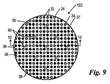
図9、10を参照すると、ウェハ・チャック122および/または222に前述の真空特性を与えるためにウェハ・チャック122、222は、間隔を開けられてそれらの間に複数のチャネル36を区画する複数のピン32、33を備えたステンレス鋼またはアルミニウムから一体で形成される。円形の断面を有して図示されているが、複数のピン32、33の各々は多角形の形状を含めた事実上どのような所望の断面形状を有することも可能であり、通常では3ミリメートルのピッチを有する。複数のピンのうちの1つまたは複数が中空であり、図11に示されるように通路35から延びて基板14に面する開口部で終結する貫通路34を形成している。これらは、重なり合う基板14の部分の屈曲を防止するために約2ミリメートルの直径を有する貫通路を備えたピン32で示されている。
Referring to FIGS. 9 and 10, to provide the aforementioned vacuum characteristics to the wafer chucks 122 and / or 222, the wafer chucks 122, 222 are spaced apart to define a plurality of
ピン32の各々は共有通路35と流体連絡して示されているが、これは必要条件ではない。そうではなく、複数のピン32の各々にある貫通路34は単位時間当たりにこれを通過する流体の量と方向が残りのピン32に関連する貫通路34を通る流体流量と無関係になるように個別に対処されてもよい。これは残りのピン32と流体連絡している通路とは異なる通路と流体連絡している1つまたは複数のピン32を置くことによって達成される。さらなる実施形態では、貫通路34は階段式構造を含むこともある。複数のピン34は基板14が置かれているランド37によって取り囲まれてもよい。チャネル36は通常、開口40を介して共有通路39と流体連絡している。
Although each of the
図10および11を参照すると、基板14はチャネル36および/または貫通路34を通る流体流によって生成される曲げ力FCによってウェハ・チャック122上に保持される。この目的のために、通路35が圧力制御システム41と流体連絡しており、通路39が圧力制御システム43と流体連絡している。両方の圧力制御システム41、43がこれらとデータ通信しているプロセッサ45の制御下で運転される。この目的のために、プロセッサは図2〜11に関連して述べられた流体流を実行するためにプロセッサによって動作されるコンピュータ読み取り可能な符号を含んでいる。ウェハ・チャック122上に配置されると、ウェハ・チャック122に面した基板14の一方の面はピン32、33に相対して載せられる。曲げ力FCの存在下、および分離強制力FSの不在下では、基板14に面する貫通路34の端部はピン32、33に面して載せられた面47によって実質的に密閉されている。面47による密閉の結果として貫通路34とチャネル36の間で流体は流れない。
With reference to FIGS. 10 and 11, the
分離強制力FSが加わると、固化インプリンティング層12と重なっている面47の部分はピン32および/または33から分離される。分離を行うために必要とされる分離強制力FSの大きさを減らすことによってこの分離を促進させるために、ピン32はウェハ・チャック122の領域全域にわたって配置されている。貫通路34を通って流れる流体は可変の力F2がチャッキング力F1より小さくなるように選択される。通常、チャッキング力F1は十分な真空下で圧力制御システム43を動作させることによって生成される。可変の力F2が加圧状態で動作させられるとき、曲げ領域24とウェハ・チャック122の間に配置された容積内で約200キロ・パスカル(kPa)の圧力を生成させると十分な大きさである。これは普通、曲げ領域24で約10ミクロンの基板14の移動が生じる。密閉が破られる結果として、貫通路34はチャネル36と開口40を介して通路39と流体連絡状態に置かれる。これは曲げ領域24と重なっている曲げ力FCの大きさをさらに小さくし、したがって、領域24内の基板14の曲げ/変形が促されるのでインプリンティング層12からテンプレート10を分離させるために必要とされる分離強制力FSを小さくすることができる。
When the separation forcing force F S is applied, the portion of the
図12を参照すると、代替の実施形態において、ウェハ・チャック322はピン32、33の使用を伴わずに前述の真空特性を得ることが可能である。この目的のために、ウェハ・チャック322の面49は複数の開口50、52を含み、これらはこれらを通る流体の流れを有するように構成され、流れの大きさと方向はほかの開口50、52を通る流体の流れと無関係にされる。開口は、これと重なり合う基板14の部分の屈曲の可能性を低減させるのに十分ように、通常では3ミリメートルのピッチと2ミリメートルの直径を有する。
Referring to FIG. 12, in an alternative embodiment, the wafer chuck 322 can obtain the aforementioned vacuum characteristics without the use of
この例では、開口50が共有通路53と流体連絡しており、開口52が共有通路55と流体連絡している。曲げ力FCは間隔を置かれた複数の開口50、52のうちの1つまたは複数を通って流れる流体によって生成される。分離の前に、間隔を置かれた複数の開口50、52の部分は第1の流量、0sccm以上でこれらを通過する流体を有している。分離強制力FSが与えられれば、流体は第1の流量とは異なる流量で開口50、52を通過することが可能となる。特に、開口50、52を通過する流体の流量は分離強制力FSの存在に応答して変わることが可能である。通常では、前述の流量変化は曲げ領域24と重なり合う開口50、52に局所化される。この流量変化は、通常、曲げ力FCの大きさを小さくするのに十分である。それ自体でこの流量変化は、通常、開口52または開口50の一方のみを通過する流体に影響を与える。例えば、曲げ領域24と重なり合う開口52を通る流量は、それにより生成される曲げ力FCが減らされるように変化する。開口50を通る流量は実質的に一定に留まる。
In this example, the
図2を参照すると、インプリンティング層12からのテンプレート10の分離をさらに補助するためにインプリンティング層は本願明細書に参照で組入れられる米国特許第6218316号明細書に開示されるように所定の波長に晒されると気体状の副生成物を生成する材料で構成されてもよい。この気体状の副生成物はインプリンティング層12とモールドの平坦面の間の界面に局所的な圧力を生成させる。この局所的な圧力はインプリンティング層12からのテンプレート10の分離を促進させる。気体状の副生成物を発生させる放射の波長は157nm、248nm、257nm、308nmまたはこれらの組合せといった波長を含む。気体状の副生成物の発生後に、インプリンティング層12への損傷を最小限にするためにテンプレート10の分離を迅速に開始することが望ましい。さらに、テンプレート10とインプリンティング層12の間に位置する気体状の副生成物はテンプレート10とインプリンティング層12の間から漏れ出すことがあり、これは望ましくない。さらに、インプリンティング層12からのテンプレート10の分離はインプリンティング層12の歪みを最小限にするためにインプリンティング層12に対して直角方向であるべきである。
Referring to FIG. 2, in order to further assist in the separation of the
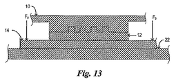
図13を参照すると、インプリンティング層12からのテンプレート10の分離をさらに補助するためにテンプレート10と基板14の間に押し付け力FPが使用されることもある。特に、押し付け力FPはテンプレート10と重なり合わない基板14の領域で基板14の付近に加えられる。この押し付け力FPは基板14をテンプレート10から離れる方向に移動させることによってテンプレート10の分離を促す。この目的のために、押し付け力FPは分離強制力FSに対して反対の方向に沿って向けられ、それにより、分離を行うために必要とされる分離強制力FSは小さくされることが可能である。押し付け力FPは図14に示されるように局所的に配置された複数の空気ノズル62によって、または図15に示されるようにアレイ162として加えられる。複数の空気ノズルの中に使用される気体は、限定はされないが窒素(N2)を含む。押し付け力FPは独立して、または図2〜12に関連して上記で検討されたような曲げ力FCの変化と併せて加えられることが可能である。
Referring to FIG. 13, sometimes pushing force F P between the
図2、16、17を参照すると、インプリンティング層12からのテンプレート10の分離をさらに補助するためにテンプレート10はテンプレート10とインプリンティング層12の間の真空密閉効果を削減するための複数のトレンチ38を含んでもよい。トレンチ66はテンプレート10とインプリンティング層12が接触するときにテンプレート10とインプリンティング層12の間に位置する空気を放出させ、したがってテンプレート10とインプリンティング層12の間の真空密閉効果を下げる。結果として、分離強制力FSの大きさが小さくされ、これは望ましい。
Referring to FIGS. 2, 16, and 17, in order to further assist in separating the
図18、図19を参照すると、さらなる実施形態においてテンプレート10は複数の穴68を含むことも可能であり、これら複数の穴68はトレンチ66と同様に機能し、それにより、穴68はテンプレート10とインプリンティング層12の間の真空密閉効果を下げるように機能する。
18, 19, in a further embodiment, the
上述の本発明の実施形態は範例である。本発明の範囲内に留まりながら多くの変更や改造が上記に引用された開示に為されることが可能である。したがって、本発明の範囲は上記の説明を参照して決定されるべきではなく、添付の特許請求項ならびに同等事項の全範囲を参照して決定されるべきである。 The above-described embodiments of the present invention are exemplary. Many changes and modifications may be made to the above cited disclosure while remaining within the scope of the invention. The scope of the invention should, therefore, be determined not with reference to the above description, but instead should be determined with reference to the appended claims along with their full scope of equivalents.
Claims (6)
前記テンプレートを前記成形層から分離させるために前記テンプレートに分離強制力を印加するステップと、
前記モールドと重ならない部分を含む前記基板の第1の領域に該基板を試料台に保持するための保持力を付与するとともに、前記モールドと重なる部分を含む基板の第2の領域に前記保持力より小さい力を付与して、前記基板の第2の領域をテンプレート方向に局所的に変形させるステップと
を有する方法であって、前記第1の領域は前記モールドと重なる基板の部分は含まず、前記第2の領域は前記第1の領域を含まないことを特徴とする方法。 A method of separating a mold contained in an imprint lithography template from a molding layer disposed on a substrate,
Applying a separation forcing force to the template to separate the template from the molding layer;
A holding force for holding the substrate on the sample stage is applied to the first region of the substrate including a portion not overlapping with the mold, and the holding force is applied to the second region of the substrate including the portion overlapping with the mold. Applying a smaller force to locally deform the second region of the substrate in a template direction , wherein the first region does not include a portion of the substrate that overlaps the mold; The method of claim 2, wherein the second region does not include the first region .
Applications Claiming Priority (7)
| Application Number | Priority Date | Filing Date | Title |
|---|---|---|---|
| US11/047,499 US7636999B2 (en) | 2005-01-31 | 2005-01-31 | Method of retaining a substrate to a wafer chuck |
| US11/047,499 | 2005-01-31 | ||
| US11/047,428 US7798801B2 (en) | 2005-01-31 | 2005-01-31 | Chucking system for nano-manufacturing |
| US11/047,428 | 2005-01-31 | ||
| US11/108,208 | 2005-04-18 | ||
| US11/108,208 US7635445B2 (en) | 2005-01-31 | 2005-04-18 | Method of separating a mold from a solidified layer disposed on a substrate |
| PCT/US2006/001160 WO2006083520A2 (en) | 2005-01-31 | 2006-01-12 | Method of separating a mold from a solidified layer disposed on a substrate |
Publications (3)
| Publication Number | Publication Date |
|---|---|
| JP2008537513A JP2008537513A (en) | 2008-09-18 |
| JP2008537513A5 JP2008537513A5 (en) | 2009-03-05 |
| JP5247153B2 true JP5247153B2 (en) | 2013-07-24 |
Family
ID=39730623
Family Applications (3)
| Application Number | Title | Priority Date | Filing Date |
|---|---|---|---|
| JP2007553123A Active JP5247153B2 (en) | 2005-01-31 | 2006-01-12 | Method for separating a mold from a solidified layer disposed on a substrate |
| JP2007553122A Pending JP2008532263A (en) | 2005-01-31 | 2006-01-12 | Method of holding substrate on wafer chuck |
| JP2007553121A Active JP4648408B2 (en) | 2005-01-31 | 2006-01-12 | Chucking system for nano machining |
Family Applications After (2)
| Application Number | Title | Priority Date | Filing Date |
|---|---|---|---|
| JP2007553122A Pending JP2008532263A (en) | 2005-01-31 | 2006-01-12 | Method of holding substrate on wafer chuck |
| JP2007553121A Active JP4648408B2 (en) | 2005-01-31 | 2006-01-12 | Chucking system for nano machining |
Country Status (4)
| Country | Link |
|---|---|
| US (1) | US7636999B2 (en) |
| JP (3) | JP5247153B2 (en) |
| SG (2) | SG159498A1 (en) |
| TW (1) | TWI327351B (en) |
Cited By (1)
| Publication number | Priority date | Publication date | Assignee | Title |
|---|---|---|---|---|
| JP2017092396A (en) * | 2015-11-16 | 2017-05-25 | キヤノン株式会社 | Imprinting device and article manufacturing method |
Families Citing this family (67)
| Publication number | Priority date | Publication date | Assignee | Title |
|---|---|---|---|---|
| US7162035B1 (en) | 2000-05-24 | 2007-01-09 | Tracer Detection Technology Corp. | Authentication method and system |
| JP4740518B2 (en) | 2000-07-17 | 2011-08-03 | ボード・オブ・リージエンツ,ザ・ユニバーシテイ・オブ・テキサス・システム | Automated liquid dispensing method and system for transfer lithography process |
| US20080160129A1 (en) * | 2006-05-11 | 2008-07-03 | Molecular Imprints, Inc. | Template Having a Varying Thickness to Facilitate Expelling a Gas Positioned Between a Substrate and the Template |
| US7641840B2 (en) * | 2002-11-13 | 2010-01-05 | Molecular Imprints, Inc. | Method for expelling gas positioned between a substrate and a mold |
| FR2869601B1 (en) * | 2004-04-28 | 2006-06-09 | Commissariat Energie Atomique | MOLD FOR NANO-PRINTING, METHOD OF MANUFACTURING SUCH MOLD AND USE OF SUCH A MOLD |
| US8334967B2 (en) * | 2004-05-28 | 2012-12-18 | Board Of Regents, The University Of Texas System | Substrate support system having a plurality of contact lands |
| US7504268B2 (en) * | 2004-05-28 | 2009-03-17 | Board Of Regents, The University Of Texas System | Adaptive shape substrate support method |
| US20060177532A1 (en) * | 2005-02-04 | 2006-08-10 | Molecular Imprints, Inc. | Imprint lithography method to control extrusion of a liquid from a desired region on a substrate |
| US7798801B2 (en) * | 2005-01-31 | 2010-09-21 | Molecular Imprints, Inc. | Chucking system for nano-manufacturing |
| US20060177535A1 (en) * | 2005-02-04 | 2006-08-10 | Molecular Imprints, Inc. | Imprint lithography template to facilitate control of liquid movement |
| JP2007134368A (en) * | 2005-11-08 | 2007-05-31 | Nikon Corp | Pattern transferring apparatus, aligner, and pattern transfer method |
| WO2007067488A2 (en) | 2005-12-08 | 2007-06-14 | Molecular Imprints, Inc. | Method and system for double-sided patterning of substrates |
| US7670530B2 (en) | 2006-01-20 | 2010-03-02 | Molecular Imprints, Inc. | Patterning substrates employing multiple chucks |
| KR100689843B1 (en) * | 2006-01-03 | 2007-03-08 | 삼성전자주식회사 | Wafer stage and chucking method of wafer using the same |
| JP2007250685A (en) * | 2006-03-14 | 2007-09-27 | Engineering System Kk | Die pressing mechanism for nano-imprint device |
| US20070231422A1 (en) * | 2006-04-03 | 2007-10-04 | Molecular Imprints, Inc. | System to vary dimensions of a thin template |
| JP4814682B2 (en) * | 2006-04-18 | 2011-11-16 | 株式会社日立ハイテクノロジーズ | Fine structure pattern transfer method and transfer apparatus |
| JP4854383B2 (en) * | 2006-05-15 | 2012-01-18 | アピックヤマダ株式会社 | Imprint method and nano-imprint apparatus |
| US8215946B2 (en) * | 2006-05-18 | 2012-07-10 | Molecular Imprints, Inc. | Imprint lithography system and method |
| US8377361B2 (en) * | 2006-11-28 | 2013-02-19 | Wei Zhang | Imprint lithography with improved substrate/mold separation |
| TW200902332A (en) * | 2007-03-26 | 2009-01-16 | Hitachi Maxell | Imprinting jig and imprinting apparatus |
| DE102007032608B4 (en) * | 2007-07-11 | 2009-05-07 | Schenck Rotec Gmbh | Method and device for centering and clamping a workpiece in a balancing machine |
| JP5069979B2 (en) * | 2007-09-03 | 2012-11-07 | 東芝機械株式会社 | Release device, supply / discharge system, and release method |
| CN101808808B (en) * | 2007-09-28 | 2013-05-01 | 东丽株式会社 | Method and device for manufacturing sheet having fine shape transferred thereon |
| US8945444B2 (en) * | 2007-12-04 | 2015-02-03 | Canon Nanotechnologies, Inc. | High throughput imprint based on contact line motion tracking control |
| US7995196B1 (en) | 2008-04-23 | 2011-08-09 | Tracer Detection Technology Corp. | Authentication method and system |
| JP5517423B2 (en) * | 2008-08-26 | 2014-06-11 | キヤノン株式会社 | Imprint apparatus and imprint method |
| NL2003380A (en) * | 2008-10-17 | 2010-04-20 | Asml Netherlands Bv | Imprint lithography apparatus and method. |
| US8652393B2 (en) | 2008-10-24 | 2014-02-18 | Molecular Imprints, Inc. | Strain and kinetics control during separation phase of imprint process |
| US8309008B2 (en) * | 2008-10-30 | 2012-11-13 | Molecular Imprints, Inc. | Separation in an imprint lithography process |
| JP5288191B2 (en) * | 2009-03-17 | 2013-09-11 | 大日本印刷株式会社 | Substrate fixing device |
| CN102438841A (en) | 2009-03-23 | 2012-05-02 | 因特瓦克公司 | A process for optimization of island to trench ratio in patterned media |
| JP5363165B2 (en) * | 2009-03-31 | 2013-12-11 | 富士フイルム株式会社 | Method and apparatus for forming fine uneven pattern |
| JP5377053B2 (en) * | 2009-04-17 | 2013-12-25 | 株式会社東芝 | Template, manufacturing method thereof, and pattern forming method |
| CN102648438A (en) * | 2009-08-26 | 2012-08-22 | 分子制模股份有限公司 | Functional nanoparticles |
| US20110084417A1 (en) * | 2009-10-08 | 2011-04-14 | Molecular Imprints, Inc. | Large area linear array nanoimprinting |
| US8747092B2 (en) | 2010-01-22 | 2014-06-10 | Nanonex Corporation | Fast nanoimprinting apparatus using deformale mold |
| JP2013517943A (en) | 2010-01-29 | 2013-05-20 | モレキュラー・インプリンツ・インコーポレーテッド | Nanoimprint lithography process to form nanoparticles |
| JP5438578B2 (en) | 2010-03-29 | 2014-03-12 | 富士フイルム株式会社 | Method and apparatus for forming fine uneven pattern |
| US8968620B2 (en) * | 2010-04-27 | 2015-03-03 | Canon Nanotechnologies, Inc. | Safe separation for nano imprinting |
| JP2014505018A (en) | 2010-11-05 | 2014-02-27 | モレキュラー・インプリンツ・インコーポレーテッド | Nanoimprint lithography of functional nanoparticles using double release layers |
| DE102010063887B4 (en) * | 2010-12-22 | 2012-07-19 | BSH Bosch und Siemens Hausgeräte GmbH | Process for producing a component suitable for pyrolysis of a cooking appliance and pyrolysis-compatible component for a cooking appliance |
| JP5875250B2 (en) * | 2011-04-28 | 2016-03-02 | キヤノン株式会社 | Imprint apparatus, imprint method, and device manufacturing method |
| EP2758227A4 (en) * | 2011-09-23 | 2015-04-29 | 1366 Tech Inc | Methods and apparati for handling, heating and cooling a substrate upon which a pattern is made by a tool in heat flowable material coating, including substrate transport, tool laydown, tool tensioning, and tool retraction |
| JP6086675B2 (en) | 2011-11-30 | 2017-03-01 | 株式会社Screenホールディングス | Printing apparatus and printing method |
| JP5759348B2 (en) | 2011-11-30 | 2015-08-05 | 株式会社Screenホールディングス | Pattern forming apparatus and pattern forming method |
| DE102012111114B4 (en) * | 2012-11-19 | 2018-10-04 | Ev Group E. Thallner Gmbh | Semiconductor processing apparatus and method |
| WO2014145360A1 (en) | 2013-03-15 | 2014-09-18 | Nanonex Corporation | Imprint lithography system and method for manufacturing |
| WO2014145826A2 (en) | 2013-03-15 | 2014-09-18 | Nanonex Corporation | System and methods of mold/substrate separation for imprint lithography |
| JP6242099B2 (en) * | 2013-07-23 | 2017-12-06 | キヤノン株式会社 | Imprint method, imprint apparatus, and device manufacturing method |
| US9771998B1 (en) | 2014-02-13 | 2017-09-26 | Hrl Laboratories, Llc | Hierarchical branched micro-truss structure and methods of manufacturing the same |
| JP6333031B2 (en) * | 2014-04-09 | 2018-05-30 | キヤノン株式会社 | Imprint apparatus and article manufacturing method |
| US9733429B2 (en) * | 2014-08-18 | 2017-08-15 | Hrl Laboratories, Llc | Stacked microlattice materials and fabrication processes |
| CN111496379B (en) * | 2014-08-19 | 2022-08-26 | 亮锐控股有限公司 | Sapphire collector for reducing mechanical damage sustained during die-level laser lift-off |
| JP6553926B2 (en) * | 2015-04-09 | 2019-07-31 | キヤノン株式会社 | Imprint apparatus, imprint method, and article manufacturing method |
| KR102572643B1 (en) * | 2015-05-13 | 2023-08-31 | 루미리즈 홀딩 비.브이. | Sapphire collector to reduce mechanical damage during die-level laser lift-off |
| US11104057B2 (en) * | 2015-12-11 | 2021-08-31 | Canon Kabushiki Kaisha | Imprint apparatus and method of imprinting a partial field |
| JP6700936B2 (en) * | 2016-04-25 | 2020-05-27 | キヤノン株式会社 | Imprint apparatus, imprint method, and article manufacturing method |
| JP6762853B2 (en) * | 2016-11-11 | 2020-09-30 | キヤノン株式会社 | Equipment, methods, and article manufacturing methods |
| TWI620351B (en) * | 2017-04-28 | 2018-04-01 | 光寶光電(常州)有限公司 | Uv led package structure, uv lighting unit, and manufacturing method of uv lighting unit |
| JP6995530B2 (en) * | 2017-08-29 | 2022-01-14 | キヤノン株式会社 | A molding device for molding a composition on a substrate using a mold and a method for manufacturing an article. |
| KR102369694B1 (en) * | 2018-02-20 | 2022-03-04 | 어플라이드 머티어리얼스, 인코포레이티드 | Patterned vacuum chuck for double-sided processing |
| JP7071231B2 (en) * | 2018-06-28 | 2022-05-18 | キヤノン株式会社 | Flattening device, flattening method, article manufacturing method, and method for creating droplet placement pattern data |
| JP7218114B2 (en) * | 2018-07-12 | 2023-02-06 | キヤノン株式会社 | Flattening apparatus, flattening method and article manufacturing method |
| JP7284639B2 (en) | 2019-06-07 | 2023-05-31 | キヤノン株式会社 | Molding apparatus and article manufacturing method |
| JP2022045186A (en) | 2020-09-08 | 2022-03-18 | キヤノン株式会社 | Molding apparatus and method of manufacturing article |
| WO2023107376A1 (en) * | 2021-12-11 | 2023-06-15 | Lam Research Corporation | Soaking and esc clamping sequence for high bow substrates |
Family Cites Families (133)
| Publication number | Priority date | Publication date | Assignee | Title |
|---|---|---|---|---|
| NL7710555A (en) | 1977-09-28 | 1979-03-30 | Philips Nv | METHOD AND DEVICE FOR MANUFACTURING INFORMATION CONTAINING PLATES. |
| DE3110341C2 (en) * | 1980-03-19 | 1983-11-17 | Hitachi, Ltd., Tokyo | Method and apparatus for aligning a thin substrate in the image plane of a copier |
| FR2513934A1 (en) * | 1981-10-06 | 1983-04-08 | Thomson Csf | METHOD FOR DISMANTLING INFORMATION CARRIER DISK AND DEVICE USING SUCH A METHOD |
| US4551192A (en) | 1983-06-30 | 1985-11-05 | International Business Machines Corporation | Electrostatic or vacuum pinchuck formed with microcircuit lithography |
| US4506184A (en) * | 1984-01-10 | 1985-03-19 | Varian Associates, Inc. | Deformable chuck driven by piezoelectric means |
| US4512848A (en) * | 1984-02-06 | 1985-04-23 | Exxon Research And Engineering Co. | Procedure for fabrication of microstructures over large areas using physical replication |
| US4559717A (en) | 1984-02-21 | 1985-12-24 | The United States Of America As Represented By The Secretary Of Commerce | Flexure hinge |
| KR900004269B1 (en) * | 1986-06-11 | 1990-06-18 | 가부시기가이샤 도시바 | Method and device for positioing 1st body and 2nd body |
| FR2604553A1 (en) | 1986-09-29 | 1988-04-01 | Rhone Poulenc Chimie | RIGID POLYMER SUBSTRATE FOR OPTICAL DISC AND OPTICAL DISCS OBTAINED FROM THE SUBSTRATE |
| JPS63131352A (en) * | 1986-11-21 | 1988-06-03 | Canon Inc | Manufacture of substrate for optical recording medium |
| US4731155A (en) * | 1987-04-15 | 1988-03-15 | General Electric Company | Process for forming a lithographic mask |
| US5028361A (en) * | 1987-11-09 | 1991-07-02 | Takeo Fujimoto | Method for molding a photosensitive composition |
| US5028366A (en) * | 1988-01-12 | 1991-07-02 | Air Products And Chemicals, Inc. | Water based mold release compositions for making molded polyurethane foam |
| JP2546350B2 (en) | 1988-09-09 | 1996-10-23 | キヤノン株式会社 | Alignment device |
| JPH02166645A (en) * | 1988-12-21 | 1990-06-27 | Canon Inc | Manufacture of substrate for optical recording medium |
| US5110514A (en) * | 1989-05-01 | 1992-05-05 | Soane Technologies, Inc. | Controlled casting of a shrinkable material |
| US4932358A (en) * | 1989-05-18 | 1990-06-12 | Genus, Inc. | Perimeter wafer seal |
| US5151754A (en) | 1989-10-06 | 1992-09-29 | Kabushiki Kaisha Toshiba | Method and an apparatus for measuring a displacement between two objects and a method and an apparatus for measuring a gap distance between two objects |
| DE4029912A1 (en) * | 1990-09-21 | 1992-03-26 | Philips Patentverwaltung | METHOD FOR FORMING AT LEAST ONE TRENCH IN A SUBSTRATE LAYER |
| US5331371A (en) * | 1990-09-26 | 1994-07-19 | Canon Kabushiki Kaisha | Alignment and exposure method |
| US5362940A (en) | 1990-11-09 | 1994-11-08 | Litel Instruments | Use of Fresnel zone plates for material processing |
| JPH0521584A (en) * | 1991-07-16 | 1993-01-29 | Nikon Corp | Retaining equipment |
| JPH0580530A (en) | 1991-09-24 | 1993-04-02 | Hitachi Ltd | Production of thin film pattern |
| JP2867194B2 (en) | 1992-02-05 | 1999-03-08 | 東京エレクトロン株式会社 | Processing device and processing method |
| US5545367A (en) * | 1992-04-15 | 1996-08-13 | Soane Technologies, Inc. | Rapid prototype three dimensional stereolithography |
| US5371822A (en) | 1992-06-09 | 1994-12-06 | Digital Equipment Corporation | Method of packaging and assembling opto-electronic integrated circuits |
| US5601641A (en) * | 1992-07-21 | 1997-02-11 | Tse Industries, Inc. | Mold release composition with polybutadiene and method of coating a mold core |
| JPH06244269A (en) * | 1992-09-07 | 1994-09-02 | Mitsubishi Electric Corp | Semiconductor manufacturing apparatus, wafer vacuum chuck device thereof, and gas cleaning and nitride film formation therefor |
| DE69405451T2 (en) * | 1993-03-16 | 1998-03-12 | Koninkl Philips Electronics Nv | Method and device for producing a structured relief image from cross-linked photoresist on a flat substrate surface |
| JP2837063B2 (en) * | 1993-06-04 | 1998-12-14 | シャープ株式会社 | Method of forming resist pattern |
| US6776094B1 (en) * | 1993-10-04 | 2004-08-17 | President & Fellows Of Harvard College | Kit For Microcontact Printing |
| US5512131A (en) * | 1993-10-04 | 1996-04-30 | President And Fellows Of Harvard College | Formation of microstamped patterns on surfaces and derivative articles |
| US5776748A (en) * | 1993-10-04 | 1998-07-07 | President And Fellows Of Harvard College | Method of formation of microstamped patterns on plates for adhesion of cells and other biological materials, devices and uses therefor |
| DE4408537A1 (en) * | 1994-03-14 | 1995-09-21 | Leybold Ag | Device for the transport of substrates |
| CN1120683A (en) * | 1994-03-15 | 1996-04-17 | 松下电器产业株式会社 | Exposure method and exposure apparatus |
| US5515167A (en) * | 1994-09-13 | 1996-05-07 | Hughes Aircraft Company | Transparent optical chuck incorporating optical monitoring |
| US5563684A (en) | 1994-11-30 | 1996-10-08 | Sgs-Thomson Microelectronics, Inc. | Adaptive wafer modulator for placing a selected pattern on a semiconductor wafer |
| US5849209A (en) | 1995-03-31 | 1998-12-15 | Johnson & Johnson Vision Products, Inc. | Mold material made with additives |
| GB9509487D0 (en) * | 1995-05-10 | 1995-07-05 | Ici Plc | Micro relief element & preparation thereof |
| US5820769A (en) | 1995-05-24 | 1998-10-13 | Regents Of The University Of Minnesota | Method for making magnetic storage having discrete elements with quantized magnetic moments |
| JP2976862B2 (en) * | 1995-09-28 | 1999-11-10 | 日本電気株式会社 | Polishing equipment |
| US5849222A (en) | 1995-09-29 | 1998-12-15 | Johnson & Johnson Vision Products, Inc. | Method for reducing lens hole defects in production of contact lens blanks |
| US20040036201A1 (en) * | 2000-07-18 | 2004-02-26 | Princeton University | Methods and apparatus of field-induced pressure imprint lithography |
| US6482742B1 (en) | 2000-07-18 | 2002-11-19 | Stephen Y. Chou | Fluid pressure imprint lithography |
| US6518189B1 (en) * | 1995-11-15 | 2003-02-11 | Regents Of The University Of Minnesota | Method and apparatus for high density nanostructures |
| US6309580B1 (en) | 1995-11-15 | 2001-10-30 | Regents Of The University Of Minnesota | Release surfaces, particularly for use in nanoimprint lithography |
| US5772905A (en) * | 1995-11-15 | 1998-06-30 | Regents Of The University Of Minnesota | Nanoimprint lithography |
| US7758794B2 (en) * | 2001-10-29 | 2010-07-20 | Princeton University | Method of making an article comprising nanoscale patterns with reduced edge roughness |
| US20040137734A1 (en) * | 1995-11-15 | 2004-07-15 | Princeton University | Compositions and processes for nanoimprinting |
| US5900062A (en) * | 1995-12-28 | 1999-05-04 | Applied Materials, Inc. | Lift pin for dechucking substrates |
| US5923408A (en) * | 1996-01-31 | 1999-07-13 | Canon Kabushiki Kaisha | Substrate holding system and exposure apparatus using the same |
| US5669303A (en) | 1996-03-04 | 1997-09-23 | Motorola | Apparatus and method for stamping a surface |
| US6355198B1 (en) * | 1996-03-15 | 2002-03-12 | President And Fellows Of Harvard College | Method of forming articles including waveguides via capillary micromolding and microtransfer molding |
| US5942443A (en) * | 1996-06-28 | 1999-08-24 | Caliper Technologies Corporation | High throughput screening assay systems in microscale fluidic devices |
| US5888650A (en) * | 1996-06-03 | 1999-03-30 | Minnesota Mining And Manufacturing Company | Temperature-responsive adhesive article |
| US6074827A (en) * | 1996-07-30 | 2000-06-13 | Aclara Biosciences, Inc. | Microfluidic method for nucleic acid purification and processing |
| US5858580A (en) * | 1997-09-17 | 1999-01-12 | Numerical Technologies, Inc. | Phase shifting circuit manufacture method and apparatus |
| JPH10172897A (en) | 1996-12-05 | 1998-06-26 | Nikon Corp | Substrate adaptor, substrate holder and method for holding substrate |
| US5948470A (en) | 1997-04-28 | 1999-09-07 | Harrison; Christopher | Method of nanoscale patterning and products made thereby |
| US5996415A (en) * | 1997-04-30 | 1999-12-07 | Sensys Instruments Corporation | Apparatus and method for characterizing semiconductor wafers during processing |
| US5812629A (en) | 1997-04-30 | 1998-09-22 | Clauser; John F. | Ultrahigh resolution interferometric x-ray imaging |
| US5974150A (en) | 1997-09-30 | 1999-10-26 | Tracer Detection Technology Corp. | System and method for authentication of goods |
| US6019166A (en) * | 1997-12-30 | 2000-02-01 | Intel Corporation | Pickup chuck with an integral heatsink |
| US6304424B1 (en) * | 1998-04-03 | 2001-10-16 | Applied Materials Inc. | Method and apparatus for minimizing plasma destabilization within a semiconductor wafer processing system |
| US6198616B1 (en) * | 1998-04-03 | 2001-03-06 | Applied Materials, Inc. | Method and apparatus for supplying a chucking voltage to an electrostatic chuck within a semiconductor wafer processing system |
| JP3780700B2 (en) | 1998-05-26 | 2006-05-31 | セイコーエプソン株式会社 | Pattern forming method, pattern forming apparatus, pattern forming plate, pattern forming plate manufacturing method, color filter manufacturing method, conductive film manufacturing method, and liquid crystal panel manufacturing method |
| US6965506B2 (en) * | 1998-09-30 | 2005-11-15 | Lam Research Corporation | System and method for dechucking a workpiece from an electrostatic chuck |
| US6713238B1 (en) * | 1998-10-09 | 2004-03-30 | Stephen Y. Chou | Microscale patterning and articles formed thereby |
| US6726195B1 (en) * | 1998-10-13 | 2004-04-27 | Dek International Gmbh | Method for ensuring planarity when using a flexible, self conforming, workpiece support system |
| US6218316B1 (en) * | 1998-10-22 | 2001-04-17 | Micron Technology, Inc. | Planarization of non-planar surfaces in device fabrication |
| JP4204128B2 (en) * | 1999-01-18 | 2009-01-07 | 東京応化工業株式会社 | Substrate transport apparatus and substrate transport method |
| US6274294B1 (en) * | 1999-02-03 | 2001-08-14 | Electroformed Stents, Inc. | Cylindrical photolithography exposure process and apparatus |
| JP2000243806A (en) * | 1999-02-22 | 2000-09-08 | Tamagawa Machinery Co Ltd | Wafer heat treatment device |
| US6334960B1 (en) * | 1999-03-11 | 2002-01-01 | Board Of Regents, The University Of Texas System | Step and flash imprint lithography |
| US6160430A (en) | 1999-03-22 | 2000-12-12 | Ati International Srl | Powerup sequence artificial voltage supply circuit |
| US6305677B1 (en) | 1999-03-30 | 2001-10-23 | Lam Research Corporation | Perimeter wafer lifting |
| US6220561B1 (en) * | 1999-06-30 | 2001-04-24 | Sandia Corporation | Compound floating pivot micromechanisms |
| WO2001011431A2 (en) * | 1999-08-06 | 2001-02-15 | Applied Materials, Inc. | Method and apparatus of holding semiconductor wafers for lithography and other wafer processes |
| US6809802B1 (en) | 1999-08-19 | 2004-10-26 | Canon Kabushiki Kaisha | Substrate attracting and holding system for use in exposure apparatus |
| JP4298078B2 (en) * | 1999-08-20 | 2009-07-15 | キヤノン株式会社 | Substrate adsorption holding device, exposure apparatus using the substrate adsorption holding device, and device manufacturing method |
| JP2001127145A (en) * | 1999-08-19 | 2001-05-11 | Canon Inc | Method and device for holding substrate with suction and exposing device and device manufacturing method using the device |
| US6589889B2 (en) * | 1999-09-09 | 2003-07-08 | Alliedsignal Inc. | Contact planarization using nanoporous silica materials |
| US6512401B2 (en) | 1999-09-10 | 2003-01-28 | Intel Corporation | Output buffer for high and low voltage bus |
| US6517995B1 (en) * | 1999-09-14 | 2003-02-11 | Massachusetts Institute Of Technology | Fabrication of finely featured devices by liquid embossing |
| US6873087B1 (en) * | 1999-10-29 | 2005-03-29 | Board Of Regents, The University Of Texas System | High precision orientation alignment and gap control stages for imprint lithography processes |
| ATE294648T1 (en) * | 1999-12-23 | 2005-05-15 | Univ Massachusetts | METHOD FOR PRODUCING SUBMICRON PATTERNS ON FILM |
| US6498640B1 (en) | 1999-12-30 | 2002-12-24 | Koninklijke Philips Electronics N.V. | Method to measure alignment using latent image grating structures |
| JP2001239487A (en) * | 2000-02-29 | 2001-09-04 | Nippei Toyama Corp | Vacuum holding device for wafer conveying system and method of releasing vacuum holding condition |
| US6313567B1 (en) | 2000-04-10 | 2001-11-06 | Motorola, Inc. | Lithography chuck having piezoelectric elements, and method |
| US7859519B2 (en) * | 2000-05-01 | 2010-12-28 | Tulbert David J | Human-machine interface |
| JP4640876B2 (en) * | 2000-06-13 | 2011-03-02 | 株式会社アルバック | Substrate transfer device |
| JP2001358056A (en) * | 2000-06-15 | 2001-12-26 | Canon Inc | Exposure apparatus |
| EP2264523A3 (en) * | 2000-07-16 | 2011-11-30 | Board Of Regents, The University Of Texas System | A method of forming a pattern on a substrate in imprint lithographic processes |
| US7211214B2 (en) * | 2000-07-18 | 2007-05-01 | Princeton University | Laser assisted direct imprint lithography |
| US20050037143A1 (en) * | 2000-07-18 | 2005-02-17 | Chou Stephen Y. | Imprint lithography with improved monitoring and control and apparatus therefor |
| US7635262B2 (en) * | 2000-07-18 | 2009-12-22 | Princeton University | Lithographic apparatus for fluid pressure imprint lithography |
| US6326627B1 (en) | 2000-08-02 | 2001-12-04 | Archimedes Technology Group, Inc. | Mass filtering sputtered ion source |
| US6718630B2 (en) * | 2000-09-18 | 2004-04-13 | Matsushita Electric Industrial Co., Ltd. | Apparatus and method for mounting components on substrate |
| AU2001297642A1 (en) * | 2000-10-12 | 2002-09-04 | Board Of Regents, The University Of Texas System | Template for room temperature, low pressure micro- and nano-imprint lithography |
| JP3834469B2 (en) * | 2000-11-15 | 2006-10-18 | 富士写真フイルム株式会社 | Substrate transfer system and substrate transfer method using the same |
| TW525221B (en) * | 2000-12-04 | 2003-03-21 | Ebara Corp | Substrate processing method |
| US6612590B2 (en) | 2001-01-12 | 2003-09-02 | Tokyo Electron Limited | Apparatus and methods for manipulating semiconductor wafers |
| US6387787B1 (en) * | 2001-03-02 | 2002-05-14 | Motorola, Inc. | Lithographic template and method of formation and use |
| US6955767B2 (en) | 2001-03-22 | 2005-10-18 | Hewlett-Packard Development Company, Lp. | Scanning probe based lithographic alignment |
| US6517977B2 (en) * | 2001-03-28 | 2003-02-11 | Motorola, Inc. | Lithographic template and method of formation and use |
| US6964793B2 (en) | 2002-05-16 | 2005-11-15 | Board Of Regents, The University Of Texas System | Method for fabricating nanoscale patterns in light curable compositions using an electric field |
| US6847433B2 (en) * | 2001-06-01 | 2005-01-25 | Agere Systems, Inc. | Holder, system, and process for improving overlay in lithography |
| US6678038B2 (en) * | 2001-08-03 | 2004-01-13 | Nikon Corporation | Apparatus and methods for detecting tool-induced shift in microlithography apparatus |
| US6898064B1 (en) * | 2001-08-29 | 2005-05-24 | Lsi Logic Corporation | System and method for optimizing the electrostatic removal of a workpiece from a chuck |
| WO2003035932A1 (en) * | 2001-09-25 | 2003-05-01 | Minuta Technology Co., Ltd. | Method for forming a micro-pattern on a substrate by using capillary force |
| US20030080472A1 (en) * | 2001-10-29 | 2003-05-01 | Chou Stephen Y. | Lithographic method with bonded release layer for molding small patterns |
| US6771372B1 (en) * | 2001-11-01 | 2004-08-03 | Therma-Wave, Inc. | Rotational stage with vertical axis adjustment |
| US6621960B2 (en) | 2002-01-24 | 2003-09-16 | Oplink Communications, Inc. | Method of fabricating multiple superimposed fiber Bragg gratings |
| US6736408B2 (en) * | 2002-01-25 | 2004-05-18 | Applied Materials Inc. | Rotary vacuum-chuck with venturi formed at base of rotating shaft |
| US6759180B2 (en) | 2002-04-23 | 2004-07-06 | Hewlett-Packard Development Company, L.P. | Method of fabricating sub-lithographic sized line and space patterns for nano-imprinting lithography |
| US6849558B2 (en) * | 2002-05-22 | 2005-02-01 | The Board Of Trustees Of The Leland Stanford Junior University | Replication and transfer of microstructures and nanostructures |
| AU2003232962A1 (en) * | 2002-05-27 | 2003-12-12 | Koninklijke Philips Electronics N.V. | Method and device for transferring a pattern from a stamp to a substrate |
| US7019819B2 (en) * | 2002-11-13 | 2006-03-28 | Molecular Imprints, Inc. | Chucking system for modulating shapes of substrates |
| US6932934B2 (en) * | 2002-07-11 | 2005-08-23 | Molecular Imprints, Inc. | Formation of discontinuous films during an imprint lithography process |
| US6908861B2 (en) * | 2002-07-11 | 2005-06-21 | Molecular Imprints, Inc. | Method for imprint lithography using an electric field |
| US6900881B2 (en) * | 2002-07-11 | 2005-05-31 | Molecular Imprints, Inc. | Step and repeat imprint lithography systems |
| US7077992B2 (en) * | 2002-07-11 | 2006-07-18 | Molecular Imprints, Inc. | Step and repeat imprint lithography processes |
| US6916584B2 (en) * | 2002-08-01 | 2005-07-12 | Molecular Imprints, Inc. | Alignment methods for imprint lithography |
| US6936194B2 (en) | 2002-09-05 | 2005-08-30 | Molecular Imprints, Inc. | Functional patterning material for imprint lithography processes |
| US6980282B2 (en) | 2002-12-11 | 2005-12-27 | Molecular Imprints, Inc. | Method for modulating shapes of substrates |
| US7750059B2 (en) * | 2002-12-04 | 2010-07-06 | Hewlett-Packard Development Company, L.P. | Polymer solution for nanoimprint lithography to reduce imprint temperature and pressure |
| US6951173B1 (en) * | 2003-05-14 | 2005-10-04 | Molecular Imprints, Inc. | Assembly and method for transferring imprint lithography templates |
| US6805054B1 (en) * | 2003-05-14 | 2004-10-19 | Molecular Imprints, Inc. | Method, system and holder for transferring templates during imprint lithography processes |
| JP4090416B2 (en) * | 2003-09-30 | 2008-05-28 | 日東電工株式会社 | Separation method and separation device for workpiece with adhesive tape |
| US7798801B2 (en) * | 2005-01-31 | 2010-09-21 | Molecular Imprints, Inc. | Chucking system for nano-manufacturing |
| US20060177532A1 (en) * | 2005-02-04 | 2006-08-10 | Molecular Imprints, Inc. | Imprint lithography method to control extrusion of a liquid from a desired region on a substrate |
| US20060177535A1 (en) * | 2005-02-04 | 2006-08-10 | Molecular Imprints, Inc. | Imprint lithography template to facilitate control of liquid movement |
| US7670530B2 (en) * | 2006-01-20 | 2010-03-02 | Molecular Imprints, Inc. | Patterning substrates employing multiple chucks |
-
2005
- 2005-01-31 US US11/047,499 patent/US7636999B2/en active Active
-
2006
- 2006-01-12 JP JP2007553123A patent/JP5247153B2/en active Active
- 2006-01-12 JP JP2007553122A patent/JP2008532263A/en active Pending
- 2006-01-12 SG SG201000535-3A patent/SG159498A1/en unknown
- 2006-01-12 JP JP2007553121A patent/JP4648408B2/en active Active
- 2006-01-12 SG SG201000531-2A patent/SG158917A1/en unknown
- 2006-01-19 TW TW095102093A patent/TWI327351B/en not_active IP Right Cessation
Cited By (2)
| Publication number | Priority date | Publication date | Assignee | Title |
|---|---|---|---|---|
| JP2017092396A (en) * | 2015-11-16 | 2017-05-25 | キヤノン株式会社 | Imprinting device and article manufacturing method |
| KR102238990B1 (en) * | 2015-11-16 | 2021-04-13 | 캐논 가부시끼가이샤 | Imprint apparatus, and method of manufacturing article |
Also Published As
| Publication number | Publication date |
|---|---|
| SG158917A1 (en) | 2010-02-26 |
| JP2008537513A (en) | 2008-09-18 |
| JP2008529826A (en) | 2008-08-07 |
| US20060172553A1 (en) | 2006-08-03 |
| JP4648408B2 (en) | 2011-03-09 |
| TWI327351B (en) | 2010-07-11 |
| SG159498A1 (en) | 2010-03-30 |
| US7636999B2 (en) | 2009-12-29 |
| JP2008532263A (en) | 2008-08-14 |
| TW200636901A (en) | 2006-10-16 |
Similar Documents
| Publication | Publication Date | Title |
|---|---|---|
| JP5247153B2 (en) | Method for separating a mold from a solidified layer disposed on a substrate | |
| US7635445B2 (en) | Method of separating a mold from a solidified layer disposed on a substrate | |
| US7462028B2 (en) | Partial vacuum environment imprinting | |
| KR101056505B1 (en) | Chucking system and method for adjusting the shape of the substrate | |
| JP4514754B2 (en) | Imprint technology by capillary action | |
| JP5198282B2 (en) | Method for exhausting a gas located between a substrate and a mold | |
| US7245358B2 (en) | Substrate support system | |
| WO2006083520A2 (en) | Method of separating a mold from a solidified layer disposed on a substrate | |
| US20210129520A1 (en) | Method and device for embossing of a nanostructure | |
| JP2019192821A (en) | Molding apparatus for molding composition on substrate using mold, molding method, and article manufacturing method |
Legal Events
| Date | Code | Title | Description |
|---|---|---|---|
| A521 | Request for written amendment filed |
Free format text: JAPANESE INTERMEDIATE CODE: A523 Effective date: 20090108 |
|
| A621 | Written request for application examination |
Free format text: JAPANESE INTERMEDIATE CODE: A621 Effective date: 20090108 |
|
| A977 | Report on retrieval |
Free format text: JAPANESE INTERMEDIATE CODE: A971007 Effective date: 20110929 |
|
| A131 | Notification of reasons for refusal |
Free format text: JAPANESE INTERMEDIATE CODE: A131 Effective date: 20111011 |
|
| A601 | Written request for extension of time |
Free format text: JAPANESE INTERMEDIATE CODE: A601 Effective date: 20120111 |
|
| A602 | Written permission of extension of time |
Free format text: JAPANESE INTERMEDIATE CODE: A602 Effective date: 20120118 |
|
| A521 | Request for written amendment filed |
Free format text: JAPANESE INTERMEDIATE CODE: A523 Effective date: 20120207 |
|
| A131 | Notification of reasons for refusal |
Free format text: JAPANESE INTERMEDIATE CODE: A131 Effective date: 20121113 |
|
| A601 | Written request for extension of time |
Free format text: JAPANESE INTERMEDIATE CODE: A601 Effective date: 20130213 |
|
| A602 | Written permission of extension of time |
Free format text: JAPANESE INTERMEDIATE CODE: A602 Effective date: 20130220 |
|
| A521 | Request for written amendment filed |
Free format text: JAPANESE INTERMEDIATE CODE: A523 Effective date: 20130226 |
|
| TRDD | Decision of grant or rejection written | ||
| A01 | Written decision to grant a patent or to grant a registration (utility model) |
Free format text: JAPANESE INTERMEDIATE CODE: A01 Effective date: 20130402 |
|
| A61 | First payment of annual fees (during grant procedure) |
Free format text: JAPANESE INTERMEDIATE CODE: A61 Effective date: 20130409 |
|
| R150 | Certificate of patent or registration of utility model |
Free format text: JAPANESE INTERMEDIATE CODE: R150 Ref document number: 5247153 Country of ref document: JP Free format text: JAPANESE INTERMEDIATE CODE: R150 |
|
| FPAY | Renewal fee payment (event date is renewal date of database) |
Free format text: PAYMENT UNTIL: 20160419 Year of fee payment: 3 |
|
| R250 | Receipt of annual fees |
Free format text: JAPANESE INTERMEDIATE CODE: R250 |
|
| R250 | Receipt of annual fees |
Free format text: JAPANESE INTERMEDIATE CODE: R250 |
|
| R250 | Receipt of annual fees |
Free format text: JAPANESE INTERMEDIATE CODE: R250 |
|
| R250 | Receipt of annual fees |
Free format text: JAPANESE INTERMEDIATE CODE: R250 |
|
| R250 | Receipt of annual fees |
Free format text: JAPANESE INTERMEDIATE CODE: R250 |
|
| R250 | Receipt of annual fees |
Free format text: JAPANESE INTERMEDIATE CODE: R250 |
|
| R250 | Receipt of annual fees |
Free format text: JAPANESE INTERMEDIATE CODE: R250 |
|
| R250 | Receipt of annual fees |
Free format text: JAPANESE INTERMEDIATE CODE: R250 |
|
| R250 | Receipt of annual fees |
Free format text: JAPANESE INTERMEDIATE CODE: R250 |