JP5244331B2 - Amorphous oxide semiconductor thin film, manufacturing method thereof, thin film transistor manufacturing method, field effect transistor, light emitting device, display device, and sputtering target - Google Patents
Amorphous oxide semiconductor thin film, manufacturing method thereof, thin film transistor manufacturing method, field effect transistor, light emitting device, display device, and sputtering target Download PDFInfo
- Publication number
- JP5244331B2 JP5244331B2 JP2007078996A JP2007078996A JP5244331B2 JP 5244331 B2 JP5244331 B2 JP 5244331B2 JP 2007078996 A JP2007078996 A JP 2007078996A JP 2007078996 A JP2007078996 A JP 2007078996A JP 5244331 B2 JP5244331 B2 JP 5244331B2
- Authority
- JP
- Japan
- Prior art keywords
- thin film
- oxide semiconductor
- semiconductor thin
- amorphous oxide
- acid
- Prior art date
- Legal status (The legal status is an assumption and is not a legal conclusion. Google has not performed a legal analysis and makes no representation as to the accuracy of the status listed.)
- Expired - Fee Related
Links
Images


Classifications
-
- H—ELECTRICITY
- H10—SEMICONDUCTOR DEVICES; ELECTRIC SOLID-STATE DEVICES NOT OTHERWISE PROVIDED FOR
- H10D—INORGANIC ELECTRIC SEMICONDUCTOR DEVICES
- H10D30/00—Field-effect transistors [FET]
- H10D30/60—Insulated-gate field-effect transistors [IGFET]
- H10D30/67—Thin-film transistors [TFT]
- H10D30/674—Thin-film transistors [TFT] characterised by the active materials
- H10D30/6755—Oxide semiconductors, e.g. zinc oxide, copper aluminium oxide or cadmium stannate
-
- C—CHEMISTRY; METALLURGY
- C04—CEMENTS; CONCRETE; ARTIFICIAL STONE; CERAMICS; REFRACTORIES
- C04B—LIME, MAGNESIA; SLAG; CEMENTS; COMPOSITIONS THEREOF, e.g. MORTARS, CONCRETE OR LIKE BUILDING MATERIALS; ARTIFICIAL STONE; CERAMICS; REFRACTORIES; TREATMENT OF NATURAL STONE
- C04B35/00—Shaped ceramic products characterised by their composition; Ceramics compositions; Processing powders of inorganic compounds preparatory to the manufacturing of ceramic products
- C04B35/01—Shaped ceramic products characterised by their composition; Ceramics compositions; Processing powders of inorganic compounds preparatory to the manufacturing of ceramic products based on oxide ceramics
- C04B35/453—Shaped ceramic products characterised by their composition; Ceramics compositions; Processing powders of inorganic compounds preparatory to the manufacturing of ceramic products based on oxide ceramics based on zinc, tin, or bismuth oxides or solid solutions thereof with other oxides, e.g. zincates, stannates or bismuthates
-
- C—CHEMISTRY; METALLURGY
- C04—CEMENTS; CONCRETE; ARTIFICIAL STONE; CERAMICS; REFRACTORIES
- C04B—LIME, MAGNESIA; SLAG; CEMENTS; COMPOSITIONS THEREOF, e.g. MORTARS, CONCRETE OR LIKE BUILDING MATERIALS; ARTIFICIAL STONE; CERAMICS; REFRACTORIES; TREATMENT OF NATURAL STONE
- C04B35/00—Shaped ceramic products characterised by their composition; Ceramics compositions; Processing powders of inorganic compounds preparatory to the manufacturing of ceramic products
- C04B35/622—Forming processes; Processing powders of inorganic compounds preparatory to the manufacturing of ceramic products
- C04B35/626—Preparing or treating the powders individually or as batches ; preparing or treating macroscopic reinforcing agents for ceramic products, e.g. fibres; mechanical aspects section B
- C04B35/62605—Treating the starting powders individually or as mixtures
- C04B35/6261—Milling
-
- C—CHEMISTRY; METALLURGY
- C23—COATING METALLIC MATERIAL; COATING MATERIAL WITH METALLIC MATERIAL; CHEMICAL SURFACE TREATMENT; DIFFUSION TREATMENT OF METALLIC MATERIAL; COATING BY VACUUM EVAPORATION, BY SPUTTERING, BY ION IMPLANTATION OR BY CHEMICAL VAPOUR DEPOSITION, IN GENERAL; INHIBITING CORROSION OF METALLIC MATERIAL OR INCRUSTATION IN GENERAL
- C23C—COATING METALLIC MATERIAL; COATING MATERIAL WITH METALLIC MATERIAL; SURFACE TREATMENT OF METALLIC MATERIAL BY DIFFUSION INTO THE SURFACE, BY CHEMICAL CONVERSION OR SUBSTITUTION; COATING BY VACUUM EVAPORATION, BY SPUTTERING, BY ION IMPLANTATION OR BY CHEMICAL VAPOUR DEPOSITION, IN GENERAL
- C23C14/00—Coating by vacuum evaporation, by sputtering or by ion implantation of the coating forming material
- C23C14/06—Coating by vacuum evaporation, by sputtering or by ion implantation of the coating forming material characterised by the coating material
- C23C14/08—Oxides
- C23C14/086—Oxides of zinc, germanium, cadmium, indium, tin, thallium or bismuth
-
- C—CHEMISTRY; METALLURGY
- C23—COATING METALLIC MATERIAL; COATING MATERIAL WITH METALLIC MATERIAL; CHEMICAL SURFACE TREATMENT; DIFFUSION TREATMENT OF METALLIC MATERIAL; COATING BY VACUUM EVAPORATION, BY SPUTTERING, BY ION IMPLANTATION OR BY CHEMICAL VAPOUR DEPOSITION, IN GENERAL; INHIBITING CORROSION OF METALLIC MATERIAL OR INCRUSTATION IN GENERAL
- C23C—COATING METALLIC MATERIAL; COATING MATERIAL WITH METALLIC MATERIAL; SURFACE TREATMENT OF METALLIC MATERIAL BY DIFFUSION INTO THE SURFACE, BY CHEMICAL CONVERSION OR SUBSTITUTION; COATING BY VACUUM EVAPORATION, BY SPUTTERING, BY ION IMPLANTATION OR BY CHEMICAL VAPOUR DEPOSITION, IN GENERAL
- C23C14/00—Coating by vacuum evaporation, by sputtering or by ion implantation of the coating forming material
- C23C14/22—Coating by vacuum evaporation, by sputtering or by ion implantation of the coating forming material characterised by the process of coating
- C23C14/34—Sputtering
- C23C14/3407—Cathode assembly for sputtering apparatus, e.g. Target
- C23C14/3414—Metallurgical or chemical aspects of target preparation, e.g. casting, powder metallurgy
-
- C—CHEMISTRY; METALLURGY
- C23—COATING METALLIC MATERIAL; COATING MATERIAL WITH METALLIC MATERIAL; CHEMICAL SURFACE TREATMENT; DIFFUSION TREATMENT OF METALLIC MATERIAL; COATING BY VACUUM EVAPORATION, BY SPUTTERING, BY ION IMPLANTATION OR BY CHEMICAL VAPOUR DEPOSITION, IN GENERAL; INHIBITING CORROSION OF METALLIC MATERIAL OR INCRUSTATION IN GENERAL
- C23C—COATING METALLIC MATERIAL; COATING MATERIAL WITH METALLIC MATERIAL; SURFACE TREATMENT OF METALLIC MATERIAL BY DIFFUSION INTO THE SURFACE, BY CHEMICAL CONVERSION OR SUBSTITUTION; COATING BY VACUUM EVAPORATION, BY SPUTTERING, BY ION IMPLANTATION OR BY CHEMICAL VAPOUR DEPOSITION, IN GENERAL
- C23C14/00—Coating by vacuum evaporation, by sputtering or by ion implantation of the coating forming material
- C23C14/22—Coating by vacuum evaporation, by sputtering or by ion implantation of the coating forming material characterised by the process of coating
- C23C14/34—Sputtering
- C23C14/3492—Variation of parameters during sputtering
-
- H—ELECTRICITY
- H10—SEMICONDUCTOR DEVICES; ELECTRIC SOLID-STATE DEVICES NOT OTHERWISE PROVIDED FOR
- H10D—INORGANIC ELECTRIC SEMICONDUCTOR DEVICES
- H10D64/00—Electrodes of devices having potential barriers
- H10D64/60—Electrodes characterised by their materials
- H10D64/62—Electrodes ohmically coupled to a semiconductor
-
- H—ELECTRICITY
- H10—SEMICONDUCTOR DEVICES; ELECTRIC SOLID-STATE DEVICES NOT OTHERWISE PROVIDED FOR
- H10D—INORGANIC ELECTRIC SEMICONDUCTOR DEVICES
- H10D99/00—Subject matter not provided for in other groups of this subclass
-
- H—ELECTRICITY
- H10—SEMICONDUCTOR DEVICES; ELECTRIC SOLID-STATE DEVICES NOT OTHERWISE PROVIDED FOR
- H10P—GENERIC PROCESSES OR APPARATUS FOR THE MANUFACTURE OR TREATMENT OF DEVICES COVERED BY CLASS H10
- H10P14/00—Formation of materials, e.g. in the shape of layers or pillars
- H10P14/20—Formation of materials, e.g. in the shape of layers or pillars of semiconductor materials
- H10P14/22—Formation of materials, e.g. in the shape of layers or pillars of semiconductor materials using physical deposition, e.g. vacuum deposition or sputtering
-
- H—ELECTRICITY
- H10—SEMICONDUCTOR DEVICES; ELECTRIC SOLID-STATE DEVICES NOT OTHERWISE PROVIDED FOR
- H10P—GENERIC PROCESSES OR APPARATUS FOR THE MANUFACTURE OR TREATMENT OF DEVICES COVERED BY CLASS H10
- H10P14/00—Formation of materials, e.g. in the shape of layers or pillars
- H10P14/20—Formation of materials, e.g. in the shape of layers or pillars of semiconductor materials
- H10P14/34—Deposited materials, e.g. layers
- H10P14/3402—Deposited materials, e.g. layers characterised by the chemical composition
- H10P14/3424—Deposited materials, e.g. layers characterised by the chemical composition being Group IIB-VIA materials
- H10P14/3426—Oxides
-
- H—ELECTRICITY
- H10—SEMICONDUCTOR DEVICES; ELECTRIC SOLID-STATE DEVICES NOT OTHERWISE PROVIDED FOR
- H10P—GENERIC PROCESSES OR APPARATUS FOR THE MANUFACTURE OR TREATMENT OF DEVICES COVERED BY CLASS H10
- H10P14/00—Formation of materials, e.g. in the shape of layers or pillars
- H10P14/20—Formation of materials, e.g. in the shape of layers or pillars of semiconductor materials
- H10P14/34—Deposited materials, e.g. layers
- H10P14/3402—Deposited materials, e.g. layers characterised by the chemical composition
- H10P14/3434—Deposited materials, e.g. layers characterised by the chemical composition being oxide semiconductor materials
-
- H—ELECTRICITY
- H10—SEMICONDUCTOR DEVICES; ELECTRIC SOLID-STATE DEVICES NOT OTHERWISE PROVIDED FOR
- H10P—GENERIC PROCESSES OR APPARATUS FOR THE MANUFACTURE OR TREATMENT OF DEVICES COVERED BY CLASS H10
- H10P14/00—Formation of materials, e.g. in the shape of layers or pillars
- H10P14/20—Formation of materials, e.g. in the shape of layers or pillars of semiconductor materials
- H10P14/34—Deposited materials, e.g. layers
- H10P14/3451—Structure
- H10P14/3452—Microstructure
- H10P14/3454—Amorphous
-
- H—ELECTRICITY
- H10—SEMICONDUCTOR DEVICES; ELECTRIC SOLID-STATE DEVICES NOT OTHERWISE PROVIDED FOR
- H10P—GENERIC PROCESSES OR APPARATUS FOR THE MANUFACTURE OR TREATMENT OF DEVICES COVERED BY CLASS H10
- H10P50/00—Etching of wafers, substrates or parts of devices
- H10P50/60—Wet etching
- H10P50/66—Wet etching of conductive or resistive materials
- H10P50/663—Wet etching of conductive or resistive materials by chemical means only
- H10P50/667—Wet etching of conductive or resistive materials by chemical means only by liquid etching only
-
- C—CHEMISTRY; METALLURGY
- C04—CEMENTS; CONCRETE; ARTIFICIAL STONE; CERAMICS; REFRACTORIES
- C04B—LIME, MAGNESIA; SLAG; CEMENTS; COMPOSITIONS THEREOF, e.g. MORTARS, CONCRETE OR LIKE BUILDING MATERIALS; ARTIFICIAL STONE; CERAMICS; REFRACTORIES; TREATMENT OF NATURAL STONE
- C04B2235/00—Aspects relating to ceramic starting mixtures or sintered ceramic products
- C04B2235/02—Composition of constituents of the starting material or of secondary phases of the final product
- C04B2235/30—Constituents and secondary phases not being of a fibrous nature
- C04B2235/32—Metal oxides, mixed metal oxides, or oxide-forming salts thereof, e.g. carbonates, nitrates, (oxy)hydroxides, chlorides
- C04B2235/3224—Rare earth oxide or oxide forming salts thereof, e.g. scandium oxide
- C04B2235/3227—Lanthanum oxide or oxide-forming salts thereof
-
- C—CHEMISTRY; METALLURGY
- C04—CEMENTS; CONCRETE; ARTIFICIAL STONE; CERAMICS; REFRACTORIES
- C04B—LIME, MAGNESIA; SLAG; CEMENTS; COMPOSITIONS THEREOF, e.g. MORTARS, CONCRETE OR LIKE BUILDING MATERIALS; ARTIFICIAL STONE; CERAMICS; REFRACTORIES; TREATMENT OF NATURAL STONE
- C04B2235/00—Aspects relating to ceramic starting mixtures or sintered ceramic products
- C04B2235/02—Composition of constituents of the starting material or of secondary phases of the final product
- C04B2235/30—Constituents and secondary phases not being of a fibrous nature
- C04B2235/32—Metal oxides, mixed metal oxides, or oxide-forming salts thereof, e.g. carbonates, nitrates, (oxy)hydroxides, chlorides
- C04B2235/3224—Rare earth oxide or oxide forming salts thereof, e.g. scandium oxide
- C04B2235/3229—Cerium oxides or oxide-forming salts thereof
-
- C—CHEMISTRY; METALLURGY
- C04—CEMENTS; CONCRETE; ARTIFICIAL STONE; CERAMICS; REFRACTORIES
- C04B—LIME, MAGNESIA; SLAG; CEMENTS; COMPOSITIONS THEREOF, e.g. MORTARS, CONCRETE OR LIKE BUILDING MATERIALS; ARTIFICIAL STONE; CERAMICS; REFRACTORIES; TREATMENT OF NATURAL STONE
- C04B2235/00—Aspects relating to ceramic starting mixtures or sintered ceramic products
- C04B2235/02—Composition of constituents of the starting material or of secondary phases of the final product
- C04B2235/30—Constituents and secondary phases not being of a fibrous nature
- C04B2235/32—Metal oxides, mixed metal oxides, or oxide-forming salts thereof, e.g. carbonates, nitrates, (oxy)hydroxides, chlorides
- C04B2235/3284—Zinc oxides, zincates, cadmium oxides, cadmiates, mercury oxides, mercurates or oxide forming salts thereof
-
- C—CHEMISTRY; METALLURGY
- C04—CEMENTS; CONCRETE; ARTIFICIAL STONE; CERAMICS; REFRACTORIES
- C04B—LIME, MAGNESIA; SLAG; CEMENTS; COMPOSITIONS THEREOF, e.g. MORTARS, CONCRETE OR LIKE BUILDING MATERIALS; ARTIFICIAL STONE; CERAMICS; REFRACTORIES; TREATMENT OF NATURAL STONE
- C04B2235/00—Aspects relating to ceramic starting mixtures or sintered ceramic products
- C04B2235/02—Composition of constituents of the starting material or of secondary phases of the final product
- C04B2235/30—Constituents and secondary phases not being of a fibrous nature
- C04B2235/32—Metal oxides, mixed metal oxides, or oxide-forming salts thereof, e.g. carbonates, nitrates, (oxy)hydroxides, chlorides
- C04B2235/3286—Gallium oxides, gallates, indium oxides, indates, thallium oxides, thallates or oxide forming salts thereof, e.g. zinc gallate
-
- C—CHEMISTRY; METALLURGY
- C04—CEMENTS; CONCRETE; ARTIFICIAL STONE; CERAMICS; REFRACTORIES
- C04B—LIME, MAGNESIA; SLAG; CEMENTS; COMPOSITIONS THEREOF, e.g. MORTARS, CONCRETE OR LIKE BUILDING MATERIALS; ARTIFICIAL STONE; CERAMICS; REFRACTORIES; TREATMENT OF NATURAL STONE
- C04B2235/00—Aspects relating to ceramic starting mixtures or sintered ceramic products
- C04B2235/02—Composition of constituents of the starting material or of secondary phases of the final product
- C04B2235/30—Constituents and secondary phases not being of a fibrous nature
- C04B2235/32—Metal oxides, mixed metal oxides, or oxide-forming salts thereof, e.g. carbonates, nitrates, (oxy)hydroxides, chlorides
- C04B2235/3293—Tin oxides, stannates or oxide forming salts thereof, e.g. indium tin oxide [ITO]
-
- C—CHEMISTRY; METALLURGY
- C04—CEMENTS; CONCRETE; ARTIFICIAL STONE; CERAMICS; REFRACTORIES
- C04B—LIME, MAGNESIA; SLAG; CEMENTS; COMPOSITIONS THEREOF, e.g. MORTARS, CONCRETE OR LIKE BUILDING MATERIALS; ARTIFICIAL STONE; CERAMICS; REFRACTORIES; TREATMENT OF NATURAL STONE
- C04B2235/00—Aspects relating to ceramic starting mixtures or sintered ceramic products
- C04B2235/65—Aspects relating to heat treatments of ceramic bodies such as green ceramics or pre-sintered ceramics, e.g. burning, sintering or melting processes
- C04B2235/656—Aspects relating to heat treatments of ceramic bodies such as green ceramics or pre-sintered ceramics, e.g. burning, sintering or melting processes characterised by specific heating conditions during heat treatment
- C04B2235/6562—Heating rate
-
- C—CHEMISTRY; METALLURGY
- C04—CEMENTS; CONCRETE; ARTIFICIAL STONE; CERAMICS; REFRACTORIES
- C04B—LIME, MAGNESIA; SLAG; CEMENTS; COMPOSITIONS THEREOF, e.g. MORTARS, CONCRETE OR LIKE BUILDING MATERIALS; ARTIFICIAL STONE; CERAMICS; REFRACTORIES; TREATMENT OF NATURAL STONE
- C04B2235/00—Aspects relating to ceramic starting mixtures or sintered ceramic products
- C04B2235/70—Aspects relating to sintered or melt-casted ceramic products
- C04B2235/74—Physical characteristics
- C04B2235/77—Density
-
- H—ELECTRICITY
- H10—SEMICONDUCTOR DEVICES; ELECTRIC SOLID-STATE DEVICES NOT OTHERWISE PROVIDED FOR
- H10D—INORGANIC ELECTRIC SEMICONDUCTOR DEVICES
- H10D86/00—Integrated devices formed in or on insulating or conducting substrates, e.g. formed in silicon-on-insulator [SOI] substrates or on stainless steel or glass substrates
- H10D86/40—Integrated devices formed in or on insulating or conducting substrates, e.g. formed in silicon-on-insulator [SOI] substrates or on stainless steel or glass substrates characterised by multiple TFTs
- H10D86/421—Integrated devices formed in or on insulating or conducting substrates, e.g. formed in silicon-on-insulator [SOI] substrates or on stainless steel or glass substrates characterised by multiple TFTs having a particular composition, shape or crystalline structure of the active layer
- H10D86/423—Integrated devices formed in or on insulating or conducting substrates, e.g. formed in silicon-on-insulator [SOI] substrates or on stainless steel or glass substrates characterised by multiple TFTs having a particular composition, shape or crystalline structure of the active layer comprising semiconductor materials not belonging to the Group IV, e.g. InGaZnO
-
- H—ELECTRICITY
- H10—SEMICONDUCTOR DEVICES; ELECTRIC SOLID-STATE DEVICES NOT OTHERWISE PROVIDED FOR
- H10D—INORGANIC ELECTRIC SEMICONDUCTOR DEVICES
- H10D86/00—Integrated devices formed in or on insulating or conducting substrates, e.g. formed in silicon-on-insulator [SOI] substrates or on stainless steel or glass substrates
- H10D86/40—Integrated devices formed in or on insulating or conducting substrates, e.g. formed in silicon-on-insulator [SOI] substrates or on stainless steel or glass substrates characterised by multiple TFTs
- H10D86/60—Integrated devices formed in or on insulating or conducting substrates, e.g. formed in silicon-on-insulator [SOI] substrates or on stainless steel or glass substrates characterised by multiple TFTs wherein the TFTs are in active matrices
Landscapes
- Chemical & Material Sciences (AREA)
- Engineering & Computer Science (AREA)
- Organic Chemistry (AREA)
- Materials Engineering (AREA)
- Ceramic Engineering (AREA)
- Manufacturing & Machinery (AREA)
- Metallurgy (AREA)
- Mechanical Engineering (AREA)
- Chemical Kinetics & Catalysis (AREA)
- Structural Engineering (AREA)
- Inorganic Chemistry (AREA)
- Thin Film Transistor (AREA)
- Liquid Crystal (AREA)
- Weting (AREA)
- Physical Vapour Deposition (AREA)
- Shift Register Type Memory (AREA)
- Devices For Indicating Variable Information By Combining Individual Elements (AREA)
- Physical Deposition Of Substances That Are Components Of Semiconductor Devices (AREA)
Description
本発明は、非晶質酸化物半導体薄膜、その製造方法、薄膜トランジスタの製造方法、電界効果型トランジスタ、発光装置、表示装置及びスパッタリングターゲットに関し、特に、キャリア密度が10+18cm−3未満であり、さらに、リン酸系エッチング液に対して不溶であり、かつ、蓚酸系エッチング液に対して可溶である非晶質酸化物半導体薄膜や、その製造方法などに関する。 The present invention relates to an amorphous oxide semiconductor thin film, a method for producing the same, a method for producing a thin film transistor, a field effect transistor, a light emitting device, a display device, and a sputtering target, and in particular, the carrier density is less than 10 +18 cm −3 , Furthermore, the present invention relates to an amorphous oxide semiconductor thin film that is insoluble in a phosphoric acid-based etching solution and soluble in an oxalic acid-based etching solution, a manufacturing method thereof, and the like.
LCD(液晶表示装置)や有機EL(Electro Luminescence)表示装置などのアクティブマトリックス型の画像表示装置は、表示性能、省エネルギー等の理由から広く利用されている。特に、携帯電話やPDA(個人向け携帯情報端末)、パソコンやラップトップパソコン、テレビ等の表示装置として、ほぼ主流を占めるに至っている。これらの表示装置には、一般に、TFT基板が用いられている。 2. Description of the Related Art Active matrix image display devices such as LCD (Liquid Crystal Display) and organic EL (Electro Luminescence) display devices are widely used for reasons such as display performance and energy saving. In particular, it has become almost mainstream as a display device for mobile phones, PDAs (personal personal digital assistants), personal computers, laptop computers, televisions, and the like. In these display devices, a TFT substrate is generally used.
例えば、液晶表示装置は、TFT基板と対向基板との間に液晶などの表示材料を充填し、この表示材料に対して画素ごとに選択的に電圧を印加するように構成されている。ここで、TFT基板とは、非晶質シリコン薄膜や多結晶シリコン薄膜などの半導体薄膜(半導体膜とも呼ばれる)を活性層に用いるTFT(電界効果型薄膜トランジスタ)が配置されている基板をいう。上記画像表示装置は、TFTのアクティブマトリクス回路により駆動される。一般に、TFT基板は、アレイ状にTFTが配置されているので、「TFTアレイ基板」とも呼ばれる。 For example, a liquid crystal display device is configured to fill a display material such as liquid crystal between a TFT substrate and a counter substrate, and to selectively apply a voltage to the display material for each pixel. Here, the TFT substrate refers to a substrate on which a TFT (field effect thin film transistor) using an active layer of a semiconductor thin film (also referred to as a semiconductor film) such as an amorphous silicon thin film or a polycrystalline silicon thin film is disposed. The image display device is driven by an active matrix circuit of TFT. In general, a TFT substrate is also called a “TFT array substrate” because TFTs are arranged in an array.
なお、液晶表示装置などに用いられるTFT基板は、TFTと液晶表示装置の画面の1画素との組(これを1ユニットと呼ぶ)が、ガラス基板上に縦横に配設されている。TFT基板は、ガラス基板上に、ゲート配線が例えば縦方向に等間隔で配置されており、ソース配線又はドレイン配線が横方向に等間隔で配置されている。また、ゲート電極,ソース電極及びドレイン電極が、各画素を構成する上記ユニット中にそれぞれ設けられている。 Note that in a TFT substrate used for a liquid crystal display device or the like, a set of TFTs and one pixel of a screen of the liquid crystal display device (this is called one unit) is arranged vertically and horizontally on a glass substrate. In the TFT substrate, gate wirings are arranged at regular intervals in the vertical direction on a glass substrate, and source wirings or drain wirings are arranged at regular intervals in the horizontal direction. Further, a gate electrode, a source electrode, and a drain electrode are provided in each of the units constituting each pixel.
ところで、上述のシリコン薄膜を用いるトランジスタの製造は、シラン系のガスを用いて製造するため安全性や設備費用の点で問題があった。また、非晶質シリコン薄膜は、TFTとした場合の電子移動度が約0.5cm2/Vs程度と低く、また、バンドギャップが小さいため可視光を吸収し誤動作するおそれがあった。また、多結晶シリコン薄膜は、比較的高温の熱工程を要し、エネルギー費用が高く、さらに、大型のガラス基板上に直接形成することは困難である。さらに、シリコン系半導体は、パターニングする際に、ウェットエッチングが困難であり、設備費用が高く生産性が低いドライエッチングを行う必要があった。 By the way, the manufacture of the transistor using the above-described silicon thin film has a problem in terms of safety and equipment cost because it is manufactured using a silane-based gas. In addition, the amorphous silicon thin film has a low electron mobility of about 0.5 cm 2 / Vs when used as a TFT, and has a small band gap, so that it may absorb visible light and malfunction. In addition, a polycrystalline silicon thin film requires a relatively high temperature thermal process, has high energy costs, and is difficult to form directly on a large glass substrate. Furthermore, when silicon-based semiconductors are patterned, wet etching is difficult, and it is necessary to perform dry etching with high equipment costs and low productivity.
そこで、低温での成膜が可能で、かつ、電子移動度が高い酸化物半導体薄膜を用いたTFTの開発が活発に行われている(例えば、特許文献1〜6参照)。
一般に、酸化物結晶の電子移動度は、金属イオンのs軌道の重なりが大きくなるほど、大きくなり、原子番号の大きなZn,In,Snの酸化物結晶は、0.1〜200cm2/Vsの大きな電子移動度を有する。さらに、酸化物では、酸素と金属イオンとがイオン結合しているために、化学結合の方向性がなく、結合の方向が不均一な非晶質状態でも、結晶状態の移動度に近い電子移動度を有することが可能となる。このことから、Si系半導体と異なり金属酸化物は、非晶質でも電界効果移動度の高いトランジスタを作ることが可能である。すなわち、上記特性を利用して、Zn,In,Snを含む結晶質・非晶質の金属酸化物を用いた半導体デバイスや、それを用いた回路等が様々検討されている。
Therefore, TFTs using oxide semiconductor thin films that can be formed at low temperatures and have high electron mobility are being actively developed (see, for example,
In general, the electron mobility of an oxide crystal increases as the overlap of s orbitals of metal ions increases, and a Zn, In, Sn oxide crystal having a large atomic number has a large value of 0.1 to 200 cm 2 / Vs. Has electron mobility. In addition, in an oxide, since oxygen and metal ions are ionically bonded, there is no direction of chemical bonding, and even in an amorphous state where the bonding direction is not uniform, electron mobility close to the mobility of the crystalline state It is possible to have a degree. Thus, unlike a Si-based semiconductor, a metal oxide can be a transistor with high field-effect mobility even though it is amorphous. That is, using the above characteristics, various studies have been made on semiconductor devices using crystalline and amorphous metal oxides including Zn, In, and Sn, and circuits using the same.
なお、金属酸化物を用いた技術として、In,Ga,Znを含む酸化物薄膜や、Zn,In,Snを含む酸化物薄膜について導電性の検討や蓚酸エッチング性の検討などがなされている(例えば、参考文献1及び特許文献7〜9参照)。
また、透明導電膜に関する技術として、ランタノイド類の添加による選択エッチングの検討がなされている(特許文献10)。
As a technique related to the transparent conductive film, selective etching by adding lanthanoids has been studied (Patent Document 10).
しかしながら、低温での成膜が可能でかつ移動度が高い酸化物半導体の中には、ウェットエッチング可能なものもあるが、ZnOなどのウェットエッチング可能な酸化物半導体は、PANなどの金属電極のエッチング液にも溶解する。したがって、この酸化物半導体を用いた活性層の上に、ウェットエッチングを用いたフォトリソグラフィー法で電極をパターニングすることは困難であった。このため、リフトオフ法などの、工程が多く歩留まりが低いうえ、高精細化、大面積化、量産化が困難な方法を用いる必要があった(特許文献1,6参照)。また、酸化物半導体を結晶化させると、PANなどの金属電極のエッチング液に不溶になるものもあるが、酸化物半導体自体のウェットエッチングが困難であり、また結晶化条件が複雑であった。すなわち、酸化物半導体自体をウェットエッチングし、さらに、この酸化物半導体上にウェットエッチングで電極をパターニングする方法は見出されていなかった。
なお、特許文献8〜10の技術は、あくまでも透明導電膜としての技術であり、薄膜トランジスタの活性層への適用や、蓚酸系エッチング液及びリン酸系エッチング液による選択エッチング性(例えば、リン酸系エッチング液(例えば、PAN(PAN系エッチング液)など)に対して不溶であり、かつ、蓚酸系エッチング液に対して可溶であるといった特性)の可能性については全く検討されていなかった。
However, some oxide semiconductors that can be formed at low temperatures and have high mobility can be wet-etched. However, oxide semiconductors that can be wet-etched such as ZnO can be used for metal electrodes such as PAN. It also dissolves in the etching solution. Therefore, it is difficult to pattern an electrode on the active layer using this oxide semiconductor by a photolithography method using wet etching. For this reason, it has been necessary to use a method such as a lift-off method, which has many processes and low yield, and is difficult to achieve high definition, large area, and mass production (see
Note that the techniques of
本発明は、以上のような従来の技術が有する問題を解決するために提案されたものであり、インジウム、錫、亜鉛の量を適正化することにより、リン酸系エッチング液に不溶であり、かつ、蓚酸系エッチング液に可溶な非晶質酸化物半導体薄膜や、その製造方法などの提供を目的とする。 The present invention has been proposed to solve the problems of the conventional techniques as described above, and is insoluble in a phosphoric acid-based etching solution by optimizing the amounts of indium, tin, and zinc. And it aims at provision of the amorphous oxide semiconductor thin film soluble in an oxalic acid system etching liquid, its manufacturing method, etc.
上記目的を達成するため、本発明の非晶質酸化物半導体薄膜は、キャリア密度が10+18cm−3未満であり、さらに、リン酸系エッチング液に対して不溶であり、かつ、蓚酸系エッチング液に対して可溶である。
このようにすると、蓚酸系エッチング液を用いて非晶質酸化物半導体薄膜自体をウェットエッチングし、さらに、この非晶質酸化物半導体薄膜上に、リン酸系エッチング液を用いたウェットエッチングで電極をパターニングすることができる。これにより、製造原価のコストダウンを図ることができるとともに、生産性などを向上させることができる。
In order to achieve the above object, the amorphous oxide semiconductor thin film of the present invention has a carrier density of less than 10 +18 cm −3 , is insoluble in a phosphoric acid etching solution, and is oxalic acid etching. It is soluble in liquid.
In this case, the amorphous oxide semiconductor thin film itself is wet-etched using the oxalic acid-based etching solution, and the electrode is further formed on the amorphous oxide semiconductor thin film by wet etching using the phosphoric acid-based etching solution. Can be patterned. As a result, the manufacturing cost can be reduced, and the productivity and the like can be improved.
また、好ましくは、前記リン酸系エッチング液による35℃でのエッチング速度が10nm/分未満であり、かつ、前記蓚酸系エッチング液による35℃でのエッチング速度が20nm/分以上であるとよい。
このようにすると、選択エッチング性を効果的に発揮することができるとともに、選択エッチング性を定量的に判断したり管理することができる。
Preferably, the etching rate at 35 ° C. by the phosphoric acid etching solution is less than 10 nm / min, and the etching rate at 35 ° C. by the oxalic acid etching solution is 20 nm / min or more.
In this way, the selective etching property can be effectively exhibited, and the selective etching property can be quantitatively judged and managed.
また、好ましくは、インジウム、錫、亜鉛及び酸素を含有し、インジウムの原子の数(=[In])と錫の原子の数(=[Sn])と亜鉛の原子の数(=[Zn])の合計に対する前記[Sn]の原子比が、0.1を超え0.2未満のときは下記原子比1を満たし、0.2以上0.3未満のときは下記原子比2を満たすとよい。
原子比1
0.1<[In]/([In]+[Sn]+[Zn])<0.5
0.1<[Sn]/([In]+[Sn]+[Zn])<0.2
0.3<[Zn]/([In]+[Sn]+[Zn])<0.8
原子比2
0.01<[In]/([In]+[Sn]+[Zn])<0.3
0.2≦[Sn]/([In]+[Sn]+[Zn])<0.3
0.4<[Zn]/([In]+[Sn]+[Zn])<0.8
このように、インジウム、錫、亜鉛の量を適正化することにより、リン酸系エッチング液に対して不溶であり、かつ、蓚酸系エッチング液に対して可溶な非晶質酸化物半導体膜とすることができる。
Further, it preferably contains indium, tin, zinc and oxygen, the number of indium atoms (= [In]), the number of tin atoms (= [Sn]), and the number of zinc atoms (= [Zn]). When the atomic ratio of [Sn] with respect to the sum of) exceeds 0.1 and less than 0.2, the following
0.1 <[In] / ([In] + [Sn] + [Zn]) <0.5
0.1 <[Sn] / ([In] + [Sn] + [Zn]) <0.2
0.3 <[Zn] / ([In] + [Sn] + [Zn]) <0.8
0.01 <[In] / ([In] + [Sn] + [Zn]) <0.3
0.2 ≦ [Sn] / ([In] + [Sn] + [Zn]) <0.3
0.4 <[Zn] / ([In] + [Sn] + [Zn]) <0.8
Thus, by optimizing the amounts of indium, tin, and zinc, an amorphous oxide semiconductor film that is insoluble in the phosphoric acid-based etching solution and soluble in the oxalic acid-based etching solution can do.
また、好ましくは、前記[Sn]と[Zn]の合計に対する前記[Sn]の原子比が、
0.1<[Sn]/([Sn]+[Zn])<0.3
であるとよい。
このようにすると、オンオフ比の高いトランジスタを作製することができる。
Preferably, the atomic ratio of [Sn] to the sum of [Sn] and [Zn] is
0.1 <[Sn] / ([Sn] + [Zn]) <0.3
It is good to be.
Thus, a transistor with a high on / off ratio can be manufactured.
また、好ましくは、前記インジウム以外のIIIB族(=B、Al、Ga、Tlのうち少なくとも一つ)を含有し、前記[In]と[Sn]と[Zn]とIIIB族の原子の数(=[IIIB])の合計に対する前記[IIIB]の原子比が、
0.0001<[IIIB]/([In]+[Sn]+[Zn]+[IIIB])<0.33
であるとよい。
このようにすると、キャリア密度を下げやすくなる。また、キャリア密度の低い状態が安定化しトランジスタに利用した場合の信頼性が向上する。
Preferably, it contains a group IIIB other than the indium (= at least one of B, Al, Ga, Tl), and the number of atoms of the group [In], [Sn], [Zn], and group IIIB ( = [IIIB]) to the total of [IIIB]
0.0001 <[IIIB] / ([In] + [Sn] + [Zn] + [IIIB]) <0.33
It is good to be.
This makes it easier to lower the carrier density. Further, the state where the carrier density is low is stabilized, and the reliability when used for a transistor is improved.
また、好ましくは、ランタノイド類(Ln=La,Ce,Pr,Nd,Pm,Sm,Eu,Gd,Tb,Dy,Ho,Er,Tm,Yb,Luのうち少なくとも一つ)を含有し、前記[In]と[Sn]と[Zn]とランタノイド類の原子の数(=[Ln])の合計に対する前記[Ln]の原子比が、
0.0001<[Ln]/([In]+[Sn]+[Zn]+[Ln])<0.1
であるとよい。
このようにすると、キャリア密度を下げやすくなる。また、キャリア密度の低い状態が安定化しトランジスタに利用した場合の信頼性が向上する。
なお、[ ]は、[ ]内の原子の数を表し、例えば、[Ln]はランタノイド類の原子の数を表している。
Preferably, it contains a lanthanoid (Ln = La, Ce, Pr, Nd, Pm, Sm, Eu, Gd, Tb, Dy, Ho, Er, Tm, Yb, Lu), The atomic ratio of [Ln] to the sum of [In], [Sn], [Zn] and the number of lanthanoid atoms (= [Ln]) is
0.0001 <[Ln] / ([In] + [Sn] + [Zn] + [Ln]) <0.1
It is good to be.
This makes it easier to lower the carrier density. Further, the state where the carrier density is low is stabilized, and the reliability when used for a transistor is improved.
[] Represents the number of atoms in [], for example, [Ln] represents the number of atoms of the lanthanoid.
上記目的を達成するため、本発明の非晶質酸化物半導体薄膜の製造方法は、上述した非晶質酸化物半導体薄膜の製造方法であって、前記非晶質酸化物半導体薄膜として、前記キャリア密度が10+18cm−3以上の非晶質薄膜を、基板温度150℃未満の条件で成膜する成膜工程と、前記非晶質薄膜に高抵抗化処理を施し、前記キャリア密度を10+18cm−3未満に調整するキャリア密度調整工程とを有する方法としてある。
このようにすると、大面積均一性が得やすく、例えば、大型のTFT基板などの品質を向上させることができる。
In order to achieve the above object, a method for producing an amorphous oxide semiconductor thin film according to the present invention is the above-described method for producing an amorphous oxide semiconductor thin film, wherein the carrier is used as the amorphous oxide semiconductor thin film. A film forming step of forming an amorphous thin film having a density of 10 +18 cm −3 or more under a condition that the substrate temperature is less than 150 ° C., and the amorphous thin film is subjected to a high resistance treatment, and the carrier density is set to 10 +18. and a carrier density adjusting step of adjusting to less than cm −3 .
In this way, large area uniformity can be easily obtained, and for example, the quality of a large TFT substrate can be improved.
また、好ましくは、前記高抵抗化処理が、酸素存在下で150〜650℃、0.5〜12000分の条件で行われる熱処理であるとよい。
このようにすると、品質や生産性を向上させることができる。
Preferably, the high resistance treatment is a heat treatment performed under conditions of 150 to 650 ° C. and 0.5 to 12000 minutes in the presence of oxygen.
In this way, quality and productivity can be improved.
上記目的を達成するため、本発明の薄膜トランジスタの製造方法は、活性層として、上述した非晶質酸化物半導体薄膜を用いた薄膜トランジスタの製造方法であって、前記非晶質酸化物半導体薄膜を用いた活性層を、カルボン酸を含むエッチング液でエッチングする活性層形成工程と、前記活性層より上の層にある電極層を、オキソ酸を含むエッチング液でエッチングする電極層形成工程とを有する方法としてある。
このようにすると、製造原価のコストダウンを図ることができ、また、生産性を向上させることができる。また、簡便で大面積均一性や再現性に優れている。
In order to achieve the above object, a thin film transistor manufacturing method of the present invention is a thin film transistor manufacturing method using the above-described amorphous oxide semiconductor thin film as an active layer, and uses the amorphous oxide semiconductor thin film. A method comprising: an active layer forming step of etching the active layer with an etching solution containing carboxylic acid; and an electrode layer forming step of etching the electrode layer above the active layer with an etching solution containing oxo acid It is as.
If it does in this way, the cost reduction of a manufacturing cost can be aimed at and productivity can be improved. Moreover, it is simple and excellent in large area uniformity and reproducibility.
上記目的を達成するため、本発明の電界効果型トランジスタは、活性層として、上述した非晶質酸化物半導体薄膜を用いた構成としてある。
このようにすると、製造原価のコストダウンを図ることができ、また、生産性を向上させることができる。また、この電界効果型トランジスタは、電界効果移動度が高く、信頼性が高く、活性層が透明で高精細とすることができる。
In order to achieve the above object, the field effect transistor of the present invention has a configuration using the above-described amorphous oxide semiconductor thin film as an active layer.
If it does in this way, the cost reduction of a manufacturing cost can be aimed at and productivity can be improved. In addition, this field effect transistor has high field effect mobility, high reliability, a transparent active layer, and high definition.
また、好ましくは、前記非晶質酸化物半導体薄膜がカルボン酸を含むエッチング液でエッチングされ、さらに、前記非晶質酸化物半導体薄膜上に、オキソ酸を含むエッチング液でエッチングされた電極を備えているとよい。
このようにすると、カルボン酸を含むエッチング液やオキソ酸を含むエッチング液で、非晶質酸化物半導体薄膜や電極をエッチングすることができる。
なお、通常、電極を溶解するオキソ酸を含むエッチング液に対して、非晶質酸化物半導体薄膜は耐性を有している。
また、カルボン酸を含むエッチング液としては、ITO−06N(関東化学(株)製)などの修酸系エッチング液が挙げられ、さらに、オキソ酸を含むエッチング液としては、PAN系エッチング液が挙げられる。
PAN系エッチング液は、リン酸、硝酸、酢酸を含むエッチング液であり、リン酸が約45〜95wt%、硝酸が約0.5〜5wt%、酢酸が約3〜50wt%の範囲にあるものが好ましい。蓚酸系エッチング液は、蓚酸を約0.5〜10wt%含むものが好ましい。
カルボン酸とは、カルボン酸構造(R−COOH)を酸成分とする化合物で下記のもの(例示)が挙げられる。
すなわち、下記のもの(例示)として、乳酸、リンゴ酸、クエン酸、シュウ酸(修酸)、マロン酸、コハク酸、フマル酸、マレイン酸、アコニット酸、グルタル酸、アジピン酸、アミノ酸、ニトロカルボン酸や、ギ酸(メタン酸)、酢酸(エタン酸)、プロピオン酸(プロパン酸)、酪酸(ブタン酸)、吉草酸(ペンタン酸)、カプロン酸(ヘキサン酸)、エナント酸(ヘプタン酸)、カプリル酸(オクタン酸)、ペラルゴン酸(ノナン酸)、カプリン酸(デカン酸)、ラウリン酸(ドデカン酸)、ミリスチン酸(テトラデカン酸)、ペンタデカン酸、パルミチン酸(ヘキサデカン酸、セタン酸)、マルガリン酸(ヘプタデカン酸)、ステアリン酸(オクタデカン酸)、オレイン酸、リノール酸、リノレン酸、アラキドン酸、ドコサヘキサエン酸、エイコサペンタエン酸や、安息香酸、フタル酸、イソフタル酸、テレフタル酸、サリチル酸、没食子酸、メリト酸、ケイ皮酸、ピルビン酸などが挙げられる。
また、オキソ酸(無機オキソ酸)としては、硫酸、亜硫酸、硝酸、亜硝酸、リン酸、亜リン酸、クロム酸、二クロム酸、過マンガン酸などが挙げられる。
Preferably, the amorphous oxide semiconductor thin film is etched with an etching solution containing carboxylic acid, and an electrode etched with an etching solution containing oxo acid is provided on the amorphous oxide semiconductor thin film. It is good to have.
Thus, the amorphous oxide semiconductor thin film and the electrode can be etched with an etching solution containing carboxylic acid or an etching solution containing oxo acid.
In general, the amorphous oxide semiconductor thin film is resistant to an etching solution containing an oxo acid that dissolves the electrode.
Examples of the etching solution containing carboxylic acid include oxalic acid-based etching solutions such as ITO-06N (manufactured by Kanto Chemical Co., Ltd.), and examples of the etching solution containing oxo acid include PAN-based etching solutions. It is done.
The PAN-based etching solution is an etching solution containing phosphoric acid, nitric acid, and acetic acid, and phosphoric acid is about 45 to 95 wt%, nitric acid is about 0.5 to 5 wt%, and acetic acid is about 3 to 50 wt%. Is preferred. The oxalic acid-based etching solution preferably contains about 0.5 to 10 wt% of oxalic acid.
Carboxylic acid is a compound having a carboxylic acid structure (R—COOH) as an acid component, and examples thereof include the following.
That is, the following (examples) include lactic acid, malic acid, citric acid, oxalic acid (oxalic acid), malonic acid, succinic acid, fumaric acid, maleic acid, aconitic acid, glutaric acid, adipic acid, amino acid, nitrocarboxylic acid Acid, formic acid (methanoic acid), acetic acid (ethanoic acid), propionic acid (propanoic acid), butyric acid (butanoic acid), valeric acid (pentanoic acid), caproic acid (hexanoic acid), enanthic acid (heptanoic acid), capryl Acid (octanoic acid), pelargonic acid (nonanoic acid), capric acid (decanoic acid), lauric acid (dodecanoic acid), myristic acid (tetradecanoic acid), pentadecanoic acid, palmitic acid (hexadecanoic acid, cetanoic acid), margaric acid ( (Heptadecanoic acid), stearic acid (octadecanoic acid), oleic acid, linoleic acid, linolenic acid, arachidonic acid, docosahexae Acid, and eicosapentaenoic acid, benzoic acid, phthalic acid, isophthalic acid, terephthalic acid, salicylic acid, gallic acid, mellitic acid, cinnamic acid, and pyruvic acid.
Examples of oxo acids (inorganic oxo acids) include sulfuric acid, sulfurous acid, nitric acid, nitrous acid, phosphoric acid, phosphorous acid, chromic acid, dichromic acid, and permanganic acid.
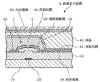
また、好ましくは、前記非晶質酸化物半導体薄膜が、層厚方向に組成が変化しており、ゲート絶縁膜から遠い第一の領域と、前記ゲート絶縁膜に近い第二の領域とを有しており、前記第二の領域の酸素濃度が、前記第一の領域の酸素濃度より濃いとよい。
このようにすると、ゲート絶縁膜側の酸素が多いので、ゲート絶縁膜との界面付近のキャリア密度が低減でき、トランジスタのオンオフ比などを向上させることができる。
Preferably, the amorphous oxide semiconductor thin film has a composition changing in a layer thickness direction, and has a first region far from the gate insulating film and a second region close to the gate insulating film. The oxygen concentration in the second region may be higher than the oxygen concentration in the first region.
In this case, since the amount of oxygen on the gate insulating film side is large, the carrier density near the interface with the gate insulating film can be reduced, and the on / off ratio of the transistor can be improved.
また、好ましくは、前記非晶質酸化物半導体薄膜が、層厚方向に組成が変化しており、ゲート絶縁膜から遠い第一の領域と、前記ゲート絶縁膜に近い第二の領域とを有しており、前記第二の領域のSn濃度が、前記第一の領域のSn濃度より薄いとよい。
このようにすると、ゲート絶縁膜側のSnが少ないので、PAN耐性を維持しつつゲート絶縁膜との界面付近のキャリア密度が低減でき、トランジスタのオンオフ比などを向上させることができる。
Preferably, the amorphous oxide semiconductor thin film has a composition changing in a layer thickness direction, and has a first region far from the gate insulating film and a second region close to the gate insulating film. The Sn concentration of the second region is preferably lower than the Sn concentration of the first region.
Thus, since Sn on the gate insulating film side is small, the carrier density near the interface with the gate insulating film can be reduced while maintaining the PAN resistance, and the on / off ratio of the transistor can be improved.
上記目的を達成するため、本発明の表示装置は、光制御素子と、この光制御素子を駆動するための、上述した電界効果型トランジスタとを備えた構成としてある。
このようにすると、製造原価のコストダウンを図ることができ、また、生産性を向上させることができる。
なお、光制御素子として、液晶を用いた素子や、無機EL、有機ELを用いた発光素子を挙げることができる。また、電界効果型トランジスタを液晶ディスプレイのスイッチング素子に用いてもよい。
In order to achieve the above object, a display device according to the present invention includes a light control element and the above-described field effect transistor for driving the light control element.
If it does in this way, the cost reduction of a manufacturing cost can be aimed at and productivity can be improved.
Note that examples of the light control element include an element using liquid crystal, and a light-emitting element using inorganic EL or organic EL. A field effect transistor may be used as a switching element of a liquid crystal display.
また、好ましくは、前記光制御素子と前記電界効果型トランジスタが一体となった構成としてもよい。
このようにすると、効果的に製造することができる。
Preferably, the light control element and the field effect transistor may be integrated.
If it does in this way, it can manufacture effectively.
上記目的を達成するため、本発明の表示装置は、上述した発光装置を用いた構成としてある。
このようにすると、製造原価のコストダウンを図ることができ、また、生産性を向上させることができる。
なお、表示装置は、画像や文字などを表示する装置である。
In order to achieve the above object, a display device of the present invention has a structure using the above-described light emitting device.
If it does in this way, the cost reduction of a manufacturing cost can be aimed at and productivity can be improved.
The display device is a device that displays images, characters, and the like.
上記目的を達成するため、本発明のスパッタリングターゲットは、インジウム、錫、亜鉛、前記インジウム以外のIIIB族(=B、Al、Ga、Tlのうち少なくとも一つ)及び酸素を含有し、インジウムの原子の数(=[In])と、錫の原子の数(=[Sn])と、亜鉛の原子の数(=[Zn])と、IIIB族の原子の数(=[IIIB])の原子比が、
0.1<[In]/([In]+[Sn]+[Zn])<0.5
0.1<[Sn]/([In]+[Sn]+[Zn])<0.2
0.3<[Zn]/([In]+[Sn]+[Zn])<0.8
0.0001<[IIIB]/([In]+[Sn]+[Zn]+[IIIB])<0.33
であり、さらに、バルク抵抗が10−3〜103mΩ、焼結密度が80%以上である。
このように、本発明は、スパッタリングターゲットとしても有効であり、製造原価のコストダウンを図ることができるとともに、生産性などを向上させることができる非晶質酸化物半導体薄膜を作製することができる。
In order to achieve the above object, the sputtering target of the present invention contains indium, tin, zinc, a group IIIB other than the indium (= at least one of B, Al, Ga, Tl) and oxygen, and an indium atom. Of atoms (= [In]), the number of tin atoms (= [Sn]), the number of zinc atoms (= [Zn]), and the number of group IIIB atoms (= [IIIB]) The ratio is
0.1 <[In] / ([In] + [Sn] + [Zn]) <0.5
0.1 <[Sn] / ([In] + [Sn] + [Zn]) <0.2
0.3 <[Zn] / ([In] + [Sn] + [Zn]) <0.8
0.0001 <[IIIB] / ([In] + [Sn] + [Zn] + [IIIB]) <0.33
Furthermore, the bulk resistance is 10 −3 to 10 3 mΩ, and the sintered density is 80% or more.
As described above, the present invention is also effective as a sputtering target, can reduce the manufacturing cost, and can produce an amorphous oxide semiconductor thin film that can improve productivity and the like. .
上記目的を達成するため、本発明のスパッタリングターゲットは、インジウム、錫、亜鉛、ランタノイド類(Ln=La,Ce,Pr,Nd,Pm,Sm,Eu,Gd,Tb,Dy,Ho,Er,Tm,Yb,Luのうち少なくとも一つ)及び酸素を含有し、インジウムの原子の数(=[In])と、錫の原子の数(=[Sn])と、亜鉛の原子の数(=[Zn])と、ランタノイド類の原子の数(=[Ln])の原子比が、
0.1<[In]/([In]+[Sn]+[Zn])<0.5
0.1<[Sn]/([In]+[Sn]+[Zn])<0.2
0.3<[Zn]/([In]+[Sn]+[Zn])<0.8
0.0001<[Ln]/([In]+[Sn]+[Zn]+[Ln])<0.1
であり、さらに、バルク抵抗が10−3〜103mΩ、焼結密度が80%以上である。
このように、本発明は、スパッタリングターゲットとしても有効であり、製造原価のコストダウンを図ることができるとともに、生産性などを向上させることができる非晶質酸化物半導体薄膜を作製することができる。
In order to achieve the above object, the sputtering target of the present invention comprises indium, tin, zinc, lanthanoids (Ln = La, Ce, Pr, Nd, Pm, Sm, Eu, Gd, Tb, Dy, Ho, Er, Tm. , Yb, Lu) and oxygen, the number of indium atoms (= [In]), the number of tin atoms (= [Sn]), and the number of zinc atoms (= [ Zn]) and the number of lanthanoid atoms (= [Ln])
0.1 <[In] / ([In] + [Sn] + [Zn]) <0.5
0.1 <[Sn] / ([In] + [Sn] + [Zn]) <0.2
0.3 <[Zn] / ([In] + [Sn] + [Zn]) <0.8
0.0001 <[Ln] / ([In] + [Sn] + [Zn] + [Ln]) <0.1
Furthermore, the bulk resistance is 10 −3 to 10 3 mΩ, and the sintered density is 80% or more.
As described above, the present invention is also effective as a sputtering target, can reduce the manufacturing cost, and can produce an amorphous oxide semiconductor thin film that can improve productivity and the like. .
以上のように、本発明によれば、インジウム、錫、亜鉛の量を適正化することにより、蓚酸系エッチング液を用いて非晶質酸化物半導体薄膜自体をウェットエッチングし、さらに、この非晶質酸化物半導体薄膜上に、リン酸系エッチング液を用いたウェットエッチングで電極をパターニングすることができる。これにより、製造原価のコストダウンを図ることができるとともに、生産性などを向上させることができる。 As described above, according to the present invention, the amorphous oxide semiconductor thin film itself is wet-etched using an oxalic acid-based etching solution by optimizing the amounts of indium, tin, and zinc. The electrode can be patterned on the oxide semiconductor thin film by wet etching using a phosphoric acid-based etching solution. As a result, the manufacturing cost can be reduced, and the productivity and the like can be improved.
以下、本発明に係る非晶質酸化物半導体薄膜、その製造方法、薄膜トランジスタの製造方法、電界効果型トランジスタ、画像表示装置及びスパッタリングターゲットの好ましい実施形態について、説明する。 Hereinafter, preferred embodiments of an amorphous oxide semiconductor thin film, a manufacturing method thereof, a manufacturing method of a thin film transistor, a field effect transistor, an image display device, and a sputtering target according to the present invention will be described.
[非晶質酸化物半導体薄膜の一実施形態]
本発明の一実施形態に係る非晶質酸化物半導体薄膜は、インジウム、錫、亜鉛の量を適正化することにより、キャリア密度が10+18cm−3未満であり、さらに、リン酸系エッチング液に対して不溶であり、かつ、蓚酸系エッチング液に対して可溶である構成としてある。このようにすると、蓚酸系エッチング液を用いて非晶質酸化物半導体薄膜自体をウェットエッチングし、さらに、この非晶質酸化物半導体薄膜上に、リン酸系エッチング液を用いたウェットエッチングで電極をパターニングすることができる。
[One Embodiment of Amorphous Oxide Semiconductor Thin Film]
The amorphous oxide semiconductor thin film according to an embodiment of the present invention has a carrier density of less than 10 +18 cm −3 by optimizing the amounts of indium, tin, and zinc. Insoluble and soluble in oxalic acid-based etching solutions. In this case, the amorphous oxide semiconductor thin film itself is wet-etched using the oxalic acid-based etching solution, and the electrode is further formed on the amorphous oxide semiconductor thin film by wet etching using the phosphoric acid-based etching solution. Can be patterned.
また、上記非晶質酸化物半導体薄膜は、室温付近(例えば、0〜40℃)でのキャリア密度が1018cm−3未満であるのが好ましく、より好ましくは2×1017cm−3未満、さらに好ましくは1017cm−3未満、特に好ましくは5×1016cm−3未満である。
この理由は、キャリア密度が1018cm−3以上になると、TFTとして駆動しないおそれがある。また、TFTとして駆動しても、ノーマリーオンになったり、閾値電圧が高くなったり、on−off比が小さくなったり、漏れ電流が大きくなったりするおそれがあるからである。
The amorphous oxide semiconductor thin film preferably has a carrier density of less than 10 18 cm −3 , more preferably less than 2 × 10 17 cm −3 near room temperature (for example, 0 to 40 ° C.). More preferably, it is less than 10 17 cm −3 , particularly preferably less than 5 × 10 16 cm −3 .
This is because if the carrier density is 10 18 cm −3 or more, the TFT may not be driven. Moreover, even if it is driven as a TFT, there is a possibility that it is normally on, the threshold voltage is increased, the on-off ratio is decreased, or the leakage current is increased.
また、非晶質酸化物半導体薄膜は、リン酸系エッチング液に対して不溶であり、かつ、蓚酸系エッチング液に対して可溶であるので、この非晶質酸化物半導体薄膜を用いた薄膜トランジスタなどを、簡便なウェトエッチングにより作製することができる。すなわち、設備費用が高く、エッチング速度が遅く、堆積物などの問題が発生するドライエッチングや、工程が複雑で歩留まりが低いうえ、高精細化、大面積化、量産化が困難なリフトオフなどを用いる必要がなくなる。したがって、製造原価のコストダウンを図ることができるとともに、生産性などを向上させることができる。 Further, since the amorphous oxide semiconductor thin film is insoluble in the phosphoric acid etching solution and soluble in the oxalic acid etching solution, the thin film transistor using the amorphous oxide semiconductor thin film Etc. can be produced by simple wet etching. In other words, the equipment cost is high, the etching rate is slow, dry etching that causes problems such as deposits, and the lift-off process is complicated and the yield is low, and it is difficult to achieve high definition, large area, and mass production. There is no need. Therefore, the manufacturing cost can be reduced, and productivity can be improved.
また、リン酸系エッチング液として、通常、PAN系エッチング液が用いられる。PAN系エッチング液は、リン酸、硝酸、酢酸を含むエッチング液であり、リン酸が約20〜95wt%、硝酸が約0.5〜5wt%、酢酸が約3〜50wt%の範囲にあるものが好ましい。また、液温は約20〜50℃が好ましい。
蓚酸系エッチング液は、蓚酸を約0.5〜10wt%含むものが好ましい。また、液温は20〜50℃が好ましい。
In addition, a PAN-based etching solution is usually used as the phosphoric acid-based etching solution. The PAN-based etching solution is an etching solution containing phosphoric acid, nitric acid, and acetic acid, and phosphoric acid is about 20 to 95 wt%, nitric acid is about 0.5 to 5 wt%, and acetic acid is about 3 to 50 wt%. Is preferred. The liquid temperature is preferably about 20 to 50 ° C.
The oxalic acid-based etching solution preferably contains about 0.5 to 10 wt% of oxalic acid. The liquid temperature is preferably 20 to 50 ° C.
上記非晶質酸化物半導体薄膜の非晶質とは、X線回折でハローパターンが観測され特定の回折線を示さないものをいい、TEM(透過型電子顕微鏡)などの観察により非晶質中に微結晶が確認できるものを含む。ただし、エッチング時の残渣となるおそれがあるため、微結晶は少ないか無い方が好ましい。 The amorphous state of the amorphous oxide semiconductor thin film refers to one in which a halo pattern is observed by X-ray diffraction and does not show a specific diffraction line. Include those in which microcrystals can be confirmed. However, since there is a possibility of becoming a residue at the time of etching, it is preferable that there are few or no microcrystals.
また、非晶質酸化物半導体薄膜の比抵抗は、通常10−2〜108Ωcmである。この理由は、比抵抗が10−2Ωcmより小さいと、電気が容易に流れ半導体薄膜として機能しないおそれがあるからである。一方、比抵抗が108Ωcmより大きいと、強い電界をかけないと半導体として機能しないおそれがあるからである。このような不具合をより有効に回避するには、比抵抗が、約10−1〜107Ωcmであるのが好ましく、より好ましくは1〜106Ωcmであり、10〜105Ωcmであるのが特に好ましい。 Moreover, the specific resistance of the amorphous oxide semiconductor thin film is usually 10 −2 to 10 8 Ωcm. This is because if the specific resistance is smaller than 10 −2 Ωcm, electricity easily flows and the semiconductor thin film may not function. On the other hand, if the specific resistance is larger than 10 8 Ωcm, it may not function as a semiconductor unless a strong electric field is applied. In order to avoid such a defect more effectively, the specific resistance is preferably about 10 −1 to 10 7 Ωcm, more preferably 1 to 10 6 Ωcm, and 10 to 10 5 Ωcm. Is particularly preferred.
また、非晶質酸化物半導体薄膜の結晶化温度は、280℃より高いことが好ましく、300℃より高いとより好ましく、350℃高いとさらに好ましく、400℃より高いと特に好ましい。この理由は、結晶化温度が280℃以下だと、キャリア密度を下げるため高抵抗化処理した際に結晶化してしまい、蓚酸エッチング速度が遅くなったりエッチング残渣が発生してしまうおそれがあるからである。 The crystallization temperature of the amorphous oxide semiconductor thin film is preferably higher than 280 ° C., more preferably higher than 300 ° C., further preferably higher than 350 ° C., and particularly preferably higher than 400 ° C. This is because if the crystallization temperature is 280 ° C. or lower, crystallization occurs when the resistance is increased to lower the carrier density, and the oxalic acid etching rate may be reduced or etching residues may be generated. is there.
また、好ましくは、リン酸系エッチング液による35℃でのエッチング速度が10nm/分未満であり、かつ、蓚酸系エッチング液による35℃でのエッチング速度が20nm/分以上であるとよい。このようにすると、選択エッチング性を効果的に発揮することができる。また、リン酸系エッチング液による35℃でのエッチング速度が10nm/分未満であるとき、リン酸系エッチング液に対して不溶であると判断し、また、蓚酸系エッチング液による35℃でのエッチング速度が20nm/分以上であるとき、蓚酸系エッチング液に対して可溶であると判断してもよい。このようにすると、選択エッチング性を定量的に判断したり管理することができる。
また、リン酸系エッチング液による35℃でのエッチング速度は、5nm/分未満がより好ましく、2nm/分がさらに好ましい。
また、蓚酸系エッチング液による35℃でのエッチング速度は、50nm/分以上がより好ましく、80nm/分以上がさらに好ましく、120nm/分以上が特に好ましい。ただし、蓚酸系エッチング液によるエッチング速度には上限があり、蓚酸系エッチング液による35℃でのエッチング速度の上限は、好ましくは800nm/分以下、より好ましくは500nm/分以下、さらに好ましくは400nm/分である。この理由は、800nm/分より大きいとエッチングの精度の制御が困難となり、ばらつきが大きくなったり耐薬品性が低下するおそれがあるからである。
Preferably, the etching rate at 35 ° C. with the phosphoric acid etching solution is less than 10 nm / min, and the etching rate at 35 ° C. with the oxalic acid etching solution is 20 nm / min or more. If it does in this way, selective etching property can be exhibited effectively. Further, when the etching rate at 35 ° C. with the phosphoric acid-based etching solution is less than 10 nm / min, it is determined that the phosphoric acid-based etching solution is insoluble, and the etching with the oxalic acid-based etching solution at 35 ° C. When the speed is 20 nm / min or more, it may be determined that the oxalic acid-based etching solution is soluble. In this way, the selective etching property can be determined quantitatively and managed.
Further, the etching rate at 35 ° C. with the phosphoric acid-based etching solution is more preferably less than 5 nm / min, and further preferably 2 nm / min.
Further, the etching rate at 35 ° C. with the oxalic acid-based etching solution is more preferably 50 nm / min or more, further preferably 80 nm / min or more, and particularly preferably 120 nm / min or more. However, there is an upper limit for the etching rate with the oxalic acid-based etching solution, and the upper limit of the etching rate at 35 ° C. with the oxalic acid-based etching solution is preferably 800 nm / min or less, more preferably 500 nm / min or less, and even more preferably 400 nm / min. Minutes. The reason for this is that if it is larger than 800 nm / min, it is difficult to control the accuracy of etching, and there is a possibility that the dispersion becomes large or the chemical resistance is lowered.
また、本実施形態の非晶質酸化物半導体薄膜は、インジウム、錫、亜鉛及び酸素を含有し、インジウムの原子の数(=[In])と錫の原子の数(=[Sn])と亜鉛の原子の数(=[Zn])の合計に対する前記[Sn]の原子比が、0.1を超え0.2未満のときは下記原子比1を満たし、0.2以上0.3未満のときは下記原子比2を満たす構成としてある。
原子比1
0.1<[In]/([In]+[Sn]+[Zn])<0.5
0.1<[Sn]/([In]+[Sn]+[Zn])<0.2
0.3<[Zn]/([In]+[Sn]+[Zn])<0.8
原子比2
0.01<[In]/([In]+[Sn]+[Zn])<0.3
0.2≦[Sn]/([In]+[Sn]+[Zn])<0.3
0.4<[Zn]/([In]+[Sn]+[Zn])<0.8
The amorphous oxide semiconductor thin film of this embodiment contains indium, tin, zinc, and oxygen, and includes the number of indium atoms (= [In]) and the number of tin atoms (= [Sn]). When the atomic ratio of [Sn] to the total number of zinc atoms (= [Zn]) is more than 0.1 and less than 0.2, the following
0.1 <[In] / ([In] + [Sn] + [Zn]) <0.5
0.1 <[Sn] / ([In] + [Sn] + [Zn]) <0.2
0.3 <[Zn] / ([In] + [Sn] + [Zn]) <0.8
0.01 <[In] / ([In] + [Sn] + [Zn]) <0.3
0.2 ≦ [Sn] / ([In] + [Sn] + [Zn]) <0.3
0.4 <[Zn] / ([In] + [Sn] + [Zn]) <0.8
上記原子比1において、[In]/([In]+[Sn]+[Zn])は、好ましくは0.1〜0.5、より好ましくは0.18〜0.48、さらに好ましくは0.2〜0.45とするとよい。この理由は、0.1より小さいと、トランジスタを構成した際に移動度が小さくなるおそれがある。また、亜鉛/錫比の変動(これは、[Zn]/[Sn]比の変動をいう。)に敏感になり、大面積におけるトランジスタの特性が不均一になるおそれがある。さらに、ターゲットの抵抗が高くなり、DCスパッタリングでの成膜が困難となるからである。また、0.5より大きいと、キャリア電子が生成しやすくなり、低抵抗化してトランジスタを構成した際に、ノーマリーオンとなったりオンオフ比が小さくなるおそれや結晶化しやすくなるおそれがあるからである。なお、結晶化すると、蓚酸系エッチング液によるエッチング速度が遅くなったりエッチング後に残渣が残るおそれがある。
In the above
また、上記原子比1において、[Sn]/([In]+[Sn]+[Zn])は、好ましくは0.1〜0.2、より好ましくは0.1〜0.19、さらに好ましくは0.11〜0.19、特に好ましくは0.11〜0.18とするとよい。この理由は、0.1より小さいとPAN耐性が失われるおそれがあるからである。また、0.2より大きいと、蓚酸エッチング性が失われたり、面内均一性が低下するおそれがある。また、ターゲットの抵抗が高くなり、DCスパッタができなくなるおそれがあるからである。
Further, in the above
また、上記原子比1において、[Zn]/([In]+[Sn]+[Zn])は、好ましくは0.3〜0.8、より好ましくは0.35〜0.75、さらに好ましくは0.4〜0.7とするとよい。この理由は、0.3より小さいと蓚酸エッチング性が失われるおそれがあるからである。また、0.8より大きいと、PAN耐性、耐熱性、面内均一性が失われるおそれや結晶化しやすくなるおそれがある。なお、結晶化すると、蓚酸系エッチング液でのエッチング速度が遅くなったりエッチング後に残渣が残るおそれがある。さらに、スパッタリングの場合に成膜速度が遅くなるおそれがあるからである。
Moreover, in the said
また、上記原子比2において、[In]/([In]+[Sn]+[Zn])は、好ましくは0.01〜0.3、より好ましくは0.05〜0.25、さらに好ましくは0.1〜0.23とするとよい。この理由は、0.1より小さいと、トランジスタを構成した際に移動度が小さくなるおそれがある。また、亜鉛/錫比の変動(これは、[Zn]/[Sn]比の変動をいう。)に敏感になり、大面積におけるトランジスタの特性が不均一になるおそれがある。さらに、ターゲットの抵抗が高くなり、DCスパッタリングでの成膜が困難となるからである。また、0.3より大きいと、キャリア電子が生成しやすくなり、低抵抗化してトランジスタを構成した際に、ノーマリーオンとなったりオンオフ比が小さくなるおそれや結晶化しやすくなるおそれがあるからである。なお、結晶化すると、蓚酸系エッチング液によるエッチング速度が遅くなったりエッチング後に残渣が残るおそれがある。
Further, in the above
また、上記原子比2において、[Sn]/([In]+[Sn]+[Zn])は、好ましくは0.2以上0.3未満、より好ましくは0.21〜0.29、さらに好ましくは0.22〜0.28とするとよい。この理由は、0.2より小さいとPAN耐性が失われるおそれがあるからである。また、0.3より大きいと、蓚酸エッチング性が失われたり、面内均一性が低下するおそれがある。また、ターゲットの抵抗が高くなり、DCスパッタができなくなるおそれがあるからである。
In the
また、上記原子比2において、[Zn]/([In]+[Sn]+[Zn])は、好ましくは0.4〜0.8、より好ましくは0.45〜0.75、さらに好ましくは0.5〜0.7とするとよい。この理由は、0.4より小さいと蓚酸エッチング性が失われるおそれがあるからである。また、0.8より大きいと、PAN耐性、耐熱性、面内均一性が失われるおそれや結晶化しやすくなるおそれがある。なお、結晶化すると、蓚酸系エッチング液でのエッチング速度が遅くなったりエッチング後に残渣が残るおそれがある。さらに、スパッタリングの場合に成膜速度が遅くなるおそれがあるからである。
このように、原子比1又は2によりインジウム、錫、亜鉛の量を適正化することによって、リン酸系エッチング液に対して不溶であり、かつ、蓚酸系エッチング液に対して可溶な非晶質酸化物半導体膜とすることができる。
In the
Thus, by optimizing the amounts of indium, tin, and zinc with an atomic ratio of 1 or 2, an amorphous material that is insoluble in a phosphoric acid etching solution and soluble in an oxalic acid etching solution. A quality oxide semiconductor film can be obtained.
また、ここで好ましくは、前記[Sn]と[Zn]の合計に対する前記[Sn]の原子比が、
0.1<[Sn]/([Sn]+[Zn])<0.3
であるとよい。すなわち、[Sn]/([Sn]+[Zn])は、0.1〜0.3が好ましく、0.11〜0.29がより好ましく、0.13〜0.27がさらに好ましく、0.15〜0.25が特に好ましい。この理由は、0.1より小さいとPAN耐性が失われるおそれがあるからである。また、0.3より大きいと蓚酸エッチング性が失われるおそれがある。さらに、錫は移動度を低下させずPAN耐性を持たせることに効果があるが、亜鉛に対する錫の比率が高くなりすぎると高抵抗化処理をしてもキャリア密度が下がりにくくなるおそれがあるからである。したがって、オンオフ比の高いトランジスタを作製するには、錫と亜鉛の比率を適性に保つことが好ましい。また、上記範囲を外れるとスパッタリングするための焼結ターゲットの抵抗が高くなるおそれがある。
Also preferably, here, the atomic ratio of [Sn] to the sum of [Sn] and [Zn] is:
0.1 <[Sn] / ([Sn] + [Zn]) <0.3
It is good to be. That is, [Sn] / ([Sn] + [Zn]) is preferably 0.1 to 0.3, more preferably 0.11 to 0.29, still more preferably 0.13 to 0.27, and 0 .15 to 0.25 is particularly preferable. This is because if it is less than 0.1, PAN resistance may be lost. On the other hand, if it exceeds 0.3, the oxalic acid etching property may be lost. Furthermore, tin is effective in imparting PAN resistance without lowering mobility, but if the ratio of tin to zinc is too high, the carrier density may not easily decrease even with high resistance treatment. It is. Therefore, in order to fabricate a transistor with a high on / off ratio, it is preferable to maintain an appropriate ratio of tin and zinc. Moreover, when it is out of the above range, the resistance of the sintering target for sputtering may be increased.
また、好ましくは、本実施形態の非晶質酸化物半導体薄膜は、前記インジウム以外のIIIB族(=B、Al、Ga、Tlのうち少なくとも一つ)を含有し、前記[In]と[Sn]と[Zn]とIIIB族の原子の数(=[IIIB])の合計に対する前記[IIIB]の原子比が、
0.0001<[IIIB]/([In]+[Sn]+[Zn]+[IIIB])<0.33
であるとよい。すなわち、[IIIB]/([In]+[Sn]+[Zn]+[IIIB])は、通常0.0001〜0.5であり、好ましくは0.001〜0.33、より好ましくは0.01〜0.25、さらに好ましくは0.03〜0.2、特に好ましくは0.05〜0.15とするとよい。この理由は、0.0001より小さいと効果が期待できず、また、0.5より大きいと、トランジスタを構成した際の移動度が低下したり、蓚酸エッチング速度が低下するおそれがあるからである。
このようにIn以外のIIIB族を含むと、キャリア密度を下げやすくなる。また、キャリア密度の低い状態が安定化しトランジスタに利用した場合の信頼性が向上する。これはIn以外のIIIB族がInよりも酸素との結合が強く酸素欠損によるキャリアの生成が起きにくいためと思われる。
Preferably, the amorphous oxide semiconductor thin film of this embodiment contains a group IIIB other than the indium (= at least one of B, Al, Ga, and Tl), and the [In] and [Sn ], [Zn], and the atomic ratio of [IIIB] to the total number of group IIIB atoms (= [IIIB])
0.0001 <[IIIB] / ([In] + [Sn] + [Zn] + [IIIB]) <0.33
It is good to be. That is, [IIIB] / ([In] + [Sn] + [Zn] + [IIIB]) is usually 0.0001 to 0.5, preferably 0.001 to 0.33, and more preferably 0. 0.01 to 0.25, more preferably 0.03 to 0.2, and particularly preferably 0.05 to 0.15. The reason is that if it is smaller than 0.0001, the effect cannot be expected, and if it is larger than 0.5, there is a possibility that the mobility when the transistor is constructed may be decreased or the oxalic acid etching rate may be decreased. .
Thus, when IIIB group other than In is included, it becomes easy to lower the carrier density. Further, the state where the carrier density is low is stabilized, and the reliability when used for a transistor is improved. This is presumably because the group IIIB other than In has a stronger bond with oxygen than In, and carriers are not easily generated due to oxygen deficiency.
また、前記IIIB族の中では、Inより原子番号の小さいB、Al、Gaが、キャリア密度の低い状態が安定化しより好ましい。
さらに、前記[In]と[IIIB]の合計に対する前記[In]の原子比が、
0.5<[In]/([In]+[IIIB])
であるとよい。すなわち、[In]/([In]+[IIIB])は、0.5より大きい方が好ましく、0.6より大きい方がより好ましく、0.7より大きい方がさらに好ましい。この理由は、0.5以下だとトランジスタの移動度が低下するおそれがあるからである。
Further, in the group IIIB, B, Al, and Ga having an atomic number smaller than that of In are more preferable because the carrier density is low.
Furthermore, the atomic ratio of [In] to the sum of [In] and [IIIB] is
0.5 <[In] / ([In] + [IIIB])
It is good to be. That is, [In] / ([In] + [IIIB]) is preferably greater than 0.5, more preferably greater than 0.6, and even more preferably greater than 0.7. The reason for this is that the mobility of the transistor may be lowered when it is 0.5 or less.
また、好ましくは、本実施形態の非晶質酸化物半導体薄膜は、ランタノイド類(Ln=La,Ce,Pr,Nd,Pm,Sm,Eu,Gd,Tb,Dy,Ho,Er,Tm,Yb,Luのうち少なくとも一つ)を含有し、前記[In]と[Sn]と[Zn]とランタノイド類の原子の数(=[Ln])の合計に対する前記[Ln]の原子比が、
0.0001<[Ln]/([In]+[Sn]+[Zn]+[Ln])<0.1
であるとよい。すなわち、[Ln]/([In]+[Sn]+[Zn]+[Ln])は、好ましくは0.0001〜0.1、より好ましくは0.001〜0.09、さらに好ましくは0.01〜0.08である。この理由は、0.0001より少ないと下記効果が期待できず、また、0.1より多いとトランジスタを構成した際の移動度が低下するおそれがあるからである。
このようにすると、キャリア密度を下げやすくなる。また、キャリア密度の低い状態が安定化しトランジスタに利用した場合の信頼性が向上する。また、上記ランタノイド類を含むと、非晶質膜の抵抗が安定しやすくトランジスタを構成した際の信頼性が向上するといった効果をも有する。
また、ランタノイド類としては、La,Ce,Pr,Nd,Pm,Sm,Eu,Gd,Tb,Dy,Ho,Er,Tm,Ybが好ましく、Sm,Eu,Gd,Tb,Dy,Ho,Er,Tm,Ybが移動度の低下が少なくより好ましい。
Preferably, the amorphous oxide semiconductor thin film of the present embodiment is made of lanthanoids (Ln = La, Ce, Pr, Nd, Pm, Sm, Eu, Gd, Tb, Dy, Ho, Er, Tm, Yb , Lu), and the atomic ratio of [Ln] to the sum of the [In], [Sn], [Zn] and the number of lanthanoid atoms (= [Ln]) is
0.0001 <[Ln] / ([In] + [Sn] + [Zn] + [Ln]) <0.1
It is good to be. That is, [Ln] / ([In] + [Sn] + [Zn] + [Ln]) is preferably 0.0001 to 0.1, more preferably 0.001 to 0.09, and still more preferably 0. 0.01 to 0.08. This is because if it is less than 0.0001, the following effects cannot be expected, and if it exceeds 0.1, the mobility when the transistor is constructed may be lowered.
This makes it easier to lower the carrier density. Further, the state where the carrier density is low is stabilized, and the reliability when used for a transistor is improved. In addition, the inclusion of the lanthanoids has an effect that the resistance of the amorphous film is easily stabilized and the reliability when a transistor is formed is improved.
As the lanthanoids, La, Ce, Pr, Nd, Pm, Sm, Eu, Gd, Tb, Dy, Ho, Er, Tm, Yb are preferable, and Sm, Eu, Gd, Tb, Dy, Ho, Er. , Tm, Yb are more preferable because of less decrease in mobility.
以上説明したように、本実施形態の非晶質酸化物半導体薄膜によれば、蓚酸系エッチング液を用いて非晶質酸化物半導体薄膜自体をウェットエッチングし、さらに、この非晶質酸化物半導体薄膜上に、リン酸系エッチング液を用いたウェットエッチングで電極をパターニングすることができる。したがって、製造原価のコストダウンを図ることができるとともに、生産性などを向上させることができる。 As described above, according to the amorphous oxide semiconductor thin film of this embodiment, the amorphous oxide semiconductor thin film itself is wet-etched using an oxalic acid-based etchant, and the amorphous oxide semiconductor thin film is further etched. The electrode can be patterned on the thin film by wet etching using a phosphoric acid-based etching solution. Therefore, the manufacturing cost can be reduced, and productivity can be improved.
[非晶質酸化物半導体薄膜の製造方法の一実施形態]
本発明の一実施形態に係る非晶質酸化物半導体薄膜の製造方法は、上記実施形態の非晶質酸化物半導体薄膜の製造方法であって、前記非晶質酸化物半導体薄膜として、キャリア密度が10+18cm−3以上の非晶質薄膜を、基板温度150℃未満の条件で成膜する成膜工程と、前記非晶質薄膜に高抵抗化処理を施し、キャリア密度を10+18cm−3未満に調整するキャリア密度調整工程とを有する方法としてある。
[One Embodiment of Method for Producing Amorphous Oxide Semiconductor Thin Film]
A method for producing an amorphous oxide semiconductor thin film according to an embodiment of the present invention is a method for producing an amorphous oxide semiconductor thin film according to the above embodiment, wherein the amorphous oxide semiconductor thin film has a carrier density. A film forming step of forming an amorphous thin film having a thickness of 10 +18 cm −3 or more under a substrate temperature of less than 150 ° C., a high resistance treatment is applied to the amorphous thin film, and a carrier density of 10 +18 cm − And a carrier density adjusting step of adjusting to less than 3 .
上記成膜には、通常、物理的成膜方法が用いられる。物理的成膜方法としては、例えば、スパッタ法、真空蒸着法、イオンプレーティング法、パルスレーザーディポジション法などを挙げることができるが、工業的には量産性の高いスパッタ法が好ましい。
スパッタ法としては、例えば、DCスパッタ法、RFスパッタ法、ACスパッタ法、ECRスパッタ法、対向ターゲットスパッタ法などが挙げられる。これらのなかでも、工業的に量産性が高く、また、RFスパッタ法よりもキャリア濃度を下げやすいDCスパッタ法や、ACスパッタ法が好ましい。また、成膜による界面の劣化を抑えて、漏れ電流を抑制したり、透明半導体薄膜におけるon−off比などの特性を向上させたりするには、膜質の制御がしやすいECRスパッタ法や、対向ターゲットスパッタ法が好ましい。
For the film formation, a physical film formation method is usually used. Examples of the physical film formation method include a sputtering method, a vacuum deposition method, an ion plating method, and a pulse laser deposition method, but industrially preferred is a sputtering method with high mass productivity.
Examples of the sputtering method include a DC sputtering method, an RF sputtering method, an AC sputtering method, an ECR sputtering method, and a counter target sputtering method. Among these, the DC sputtering method and the AC sputtering method, which are industrially high in mass productivity and can easily lower the carrier concentration than the RF sputtering method, are preferable. Moreover, in order to suppress the deterioration of the interface due to the film formation, to suppress the leakage current, and to improve the characteristics such as the on-off ratio in the transparent semiconductor thin film, Target sputtering is preferred.
また、スパッタ時における基板からターゲットまでの距離(S−T距離)は、通常150mm以下、好ましくは110mm、特に好ましくは80mm以下である。この理由は、S−T距離が短いとスパッタ時に基板がプラズマに曝されることにより、正二価元素の活性化が期待できる。また、150mmより長いと、成膜速度が遅くなり工業化に適さなくなるおそれがあるからである。 Further, the distance from the substrate to the target (ST distance) during sputtering is usually 150 mm or less, preferably 110 mm, and particularly preferably 80 mm or less. This is because if the ST distance is short, the substrate is exposed to plasma during sputtering, and activation of the positive divalent element can be expected. On the other hand, if the length is longer than 150 mm, the film formation rate becomes slow and may not be suitable for industrialization.
また、成膜する際の基板温度は、150℃未満が好ましく、100℃未満がより好ましく、50℃未満がさらに好ましい。この理由は、基板温度が150℃以上だと高抵抗化処理によりキャリ密度を低減させることが困難となるおそれがあるからである。 Further, the substrate temperature during film formation is preferably less than 150 ° C., more preferably less than 100 ° C., and even more preferably less than 50 ° C. This is because if the substrate temperature is 150 ° C. or higher, it may be difficult to reduce the carry density by the high resistance treatment.
次に、上記により成膜された非晶質薄膜に対して、高抵抗化処理を行う。この高抵抗化処理としては、酸素存在下での熱処理、プラズマ処理、オゾン処理、水蒸気処理、RTAなどを用いることができる。
また、高抵抗化処理を行った後のキャリア密度は、10+18cm−3未満が好ましく、2×10+17cm−3未満がより好ましく、10+17cm−3未満がさらに好ましい。このようにすると、非晶質酸化物半導体薄膜を用いた半導体装置の信頼性及び性能(例えば、TFTにおけるノーマリーオフなどの特性)をさらに向上させることができる。
Next, a high resistance treatment is performed on the amorphous thin film formed as described above. As this high resistance treatment, heat treatment in the presence of oxygen, plasma treatment, ozone treatment, water vapor treatment, RTA, or the like can be used.
The carrier density after the high resistance treatment is preferably less than 10 +18 cm −3 , more preferably less than 2 × 10 +17 cm −3 , and even more preferably less than 10 +17 cm −3 . In this case, the reliability and performance (for example, characteristics such as normally-off in a TFT) of a semiconductor device using an amorphous oxide semiconductor thin film can be further improved.
また、好ましくは、上記高抵抗化処理が、酸素存在下で150〜650℃、0.5〜12000分の条件で行われる熱処理であるとよく、このようにすると、品質や生産性を向上させることができる。この温度に関する理由は、熱処理の温度が150℃より低いと処理効果が発現しなかったり、時間がかかりすぎたりするおそれがあるからである。また、650℃より高いとエネルギーコストが高くなったり、タクトタイムが長くなったり、TFTとしたときの閾値電圧が大きくなったり、基板が変形したりするおそれがあるからである。このような不具合をより有効に回避するために、処理温度は、好ましくは180〜450℃、より好ましくは190〜390℃、さらに好ましくは200〜350℃であり、210〜290℃が特に好ましい。 Preferably, the high resistance treatment is a heat treatment performed under conditions of 150 to 650 ° C. and 0.5 to 12000 minutes in the presence of oxygen, and in this way, quality and productivity are improved. be able to. The reason for this temperature is that if the temperature of the heat treatment is lower than 150 ° C., the treatment effect may not be exhibited or it may take too much time. Further, if the temperature is higher than 650 ° C., the energy cost may be increased, the tact time may be increased, the threshold voltage when the TFT is used may be increased, or the substrate may be deformed. In order to avoid such trouble more effectively, the treatment temperature is preferably 180 to 450 ° C, more preferably 190 to 390 ° C, still more preferably 200 to 350 ° C, and particularly preferably 210 to 290 ° C.
また、上記時間に関する理由は、熱処理の時間が0.5分より短いと内部まで加熱する時間が不足し処理が不十分となるおそれがあるからである。また、12000分より長いと処理装置が大きくなり工業的に使用できなかったり、処理中に基板が破損・変形したりするおそれがあるからである。このような不具合をより有効に回避するために、処理時間は、好ましくは1〜600分、より好ましくは5〜360分、さらに好ましくは15〜240分であり、30〜120分が特に好ましい。
さらに、成膜時の基板温度と高抵抗化処理の温度差は50℃以上が好ましく、150℃以上がより好ましく、250℃以上が特に好ましい。この理由は、温度差が50℃未満だと高抵抗化処理の効果が十分にでずキャリア密度が低減しないおそれがあるからである。
The reason for the above time is that if the heat treatment time is shorter than 0.5 minutes, the time for heating to the inside is insufficient and the treatment may be insufficient. Further, if it is longer than 12000 minutes, the processing apparatus becomes large and cannot be used industrially, or the substrate may be damaged or deformed during processing. In order to avoid such problems more effectively, the treatment time is preferably 1 to 600 minutes, more preferably 5 to 360 minutes, still more preferably 15 to 240 minutes, and particularly preferably 30 to 120 minutes.
Furthermore, the temperature difference between the substrate temperature during film formation and the high resistance treatment is preferably 50 ° C. or higher, more preferably 150 ° C. or higher, and particularly preferably 250 ° C. or higher. This is because if the temperature difference is less than 50 ° C., the effect of the high resistance treatment is not sufficient and the carrier density may not be reduced.
以上説明したように、本実施形態の非晶質酸化物半導体薄膜の製造方法によれば、成膜時の酸素分圧でキャリア密度を調整しないので、成膜時のプラズマの分布の影響などで面内均一性が悪くなるといった不具合を回避することができる。したがって、大面積均一性が得やすく、例えば、大型のTFT基板などの品質を向上させることができる。 As described above, according to the method for manufacturing an amorphous oxide semiconductor thin film of the present embodiment, the carrier density is not adjusted by the oxygen partial pressure during film formation. Problems such as in-plane uniformity can be avoided. Therefore, it is easy to obtain large area uniformity, and for example, the quality of a large TFT substrate can be improved.
次に、上記非晶質酸化物半導体薄膜の一実施形態及びその製造方法の一実施形態に係る、実施例1〜20と比較例1〜10について、図面を参照して説明する。
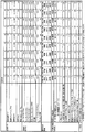
図1は、実施例1〜10に対する、成膜条件、膜組成原子比、高抵抗化処理、半導体薄膜の特性、及び、TFT特性を表した表1を示している。
また、図2は、実施例11〜20に対する、成膜条件、膜組成原子比、高抵抗化処理、半導体薄膜の特性、及び、TFT特性を表した表2を示している。
さらに、図3は、比較例1〜10に対する、成膜条件、膜組成原子比、高抵抗化処理、半導体薄膜の特性、及び、TFT特性を表した表3を示している。
Next, Examples 1 to 20 and Comparative Examples 1 to 10 according to an embodiment of the amorphous oxide semiconductor thin film and an embodiment of the manufacturing method thereof will be described with reference to the drawings.
FIG. 1 shows Table 1 showing film forming conditions, film composition atomic ratios, high resistance treatment, semiconductor thin film characteristics, and TFT characteristics for Examples 1 to 10.
FIG. 2 shows Table 2 showing film formation conditions, film composition atomic ratios, high resistance treatment, semiconductor thin film characteristics, and TFT characteristics for Examples 11 to 20.
Further, FIG. 3 shows Table 3 showing film forming conditions, film composition atomic ratios, high resistance treatment, semiconductor thin film characteristics, and TFT characteristics for Comparative Examples 1 to 10.
[実施例1]
(1)スパッタリングターゲットの製造、及び評価
1.ターゲットの製造
原料として、酸化インジウム粉末と、酸化錫粉末と、酸化亜鉛粉末とを、[In]/([In]+[Sn]+[Zn])が0.20、[Sn]/([In]+[Sn]+[Zn])が0.15、[Zn]/([In]+[Sn]+[Zn])が0.65となるように混合して、これを湿式ボールミルに供給し、72時間混合粉砕して原料微粉末を得た。
得られた原料微粉末を造粒した後、直径10cm、厚さ5mmの寸法にプレス成形して、これを焼成炉に入れ、1400℃,48時間の条件で焼成して、焼結体(ターゲット)を得た。このとき、昇温速度は、3℃/分であった。
2.ターゲットの評価
得られたターゲットにつき、密度、バルク抵抗値を測定した。その結果、理論相対密度は98%であり、四端子法により測定したバルク抵抗値は、80mΩであった。
[Example 1]
(1) Production and evaluation of sputtering target Production of target As raw materials, indium oxide powder, tin oxide powder, and zinc oxide powder, [In] / ([In] + [Sn] + [Zn]) is 0.20, [Sn] / ([[ In] + [Sn] + [Zn]) is 0.15 and [Zn] / ([In] + [Sn] + [Zn]) is 0.65, and this is mixed into a wet ball mill. The raw material fine powder was obtained by mixing and grinding for 72 hours.
After granulating the obtained raw material fine powder, it is press-molded to a size of 10 cm in diameter and 5 mm in thickness, put in a firing furnace, fired at 1400 ° C. for 48 hours, and sintered body (target ) At this time, the rate of temperature increase was 3 ° C./min.
2. Evaluation of target The density and bulk resistance value of the obtained target were measured. As a result, the theoretical relative density was 98%, and the bulk resistance value measured by the four probe method was 80 mΩ.
(2)透明半導体薄膜の成膜
上記(1)で得られたスパッタリングターゲットを、スパッタ法の一つであるRFマグネトロンスパッタリング法の成膜装置に装着し、ガラス基板(コーニング1737)上に透明導電膜を成膜した。
ここでのスパッタ条件としては、基板温度;25℃、到達圧力;5×10⁻⁴Pa、雰囲気ガス;Ar100%、スパッタ圧力(全圧);4×10⁻¹Pa、投入電力100W、成膜時間20分間、S−T距離95mmとした。
この結果、ガラス基板上に、膜厚が約100nmの透明導電性酸化物が形成された透明導電ガラスが得られた。
なお、得られた膜組成をICP法で分析したところ、[In]/([In]+[Sn]+[Zn])が0.20、[Sn]/([In]+[Sn]+[Zn])が0.15、[Zn]/([In]+[Sn]+[Zn])が0.65であった。
(2) Film formation of transparent semiconductor thin film The sputtering target obtained in the above (1) is mounted on a film formation apparatus of an RF magnetron sputtering method which is one of the sputtering methods, and a transparent conductive film is formed on a glass substrate (Corning 1737). A film was formed.
As sputtering conditions here, substrate temperature: 25 ° C., ultimate pressure: 5 × 10 −4 Pa, atmospheric gas:
As a result, a transparent conductive glass in which a transparent conductive oxide having a film thickness of about 100 nm was formed on the glass substrate was obtained.
When the obtained film composition was analyzed by the ICP method, [In] / ([In] + [Sn] + [Zn]) was 0.20, and [Sn] / ([In] + [Sn] + [Zn]) was 0.15, and [Zn] / ([In] + [Sn] + [Zn]) was 0.65.
(3)透明半導体薄膜の高抵抗化処理
上記(2)で得られた透明半導体薄膜に対して、高抵抗化処理を施した。この高抵抗化処理として、大気中(酸素存在下)280℃で2時間加熱(大気下熱処理)する、酸化処理を行った。
(3) High resistance treatment of transparent semiconductor thin film The transparent semiconductor thin film obtained in (2) above was subjected to high resistance treatment. As this high resistance treatment, an oxidation treatment was performed by heating (atmospheric heat treatment) at 280 ° C. for 2 hours in the air (in the presence of oxygen).
(4)透明半導体薄膜の物性の評価
上記(3)で得られた透明半導体薄膜のキャリア濃度、及びホール移動度をホール測定装置により測定した。キャリア濃度は5×1016cm−3、ホール移動度は3cm2/Vsであった。また、比抵抗の値は、42Ωcmであった。さらに、比抵抗の面内均一性(面内の最大値/面内の最小値)は、1.05であった。
(4) Evaluation of physical properties of transparent semiconductor thin film The carrier concentration and hole mobility of the transparent semiconductor thin film obtained in the above (3) were measured with a hole measuring device. The carrier concentration was 5 × 10 16 cm −3 and the hole mobility was 3 cm 2 / Vs. The specific resistance value was 42 Ωcm. Further, the in-plane uniformity (maximum value in the plane / minimum value in the plane) of the specific resistance was 1.05.
ホール測定装置、及びその測定条件は下記のとおりであった、
[ホール測定装置]
東陽テクニカ製:Resi Test8310
[測定条件]
室温(25℃)、0.5[T]、10−4〜10−12A、AC磁場ホール測定
The Hall measuring device and its measurement conditions were as follows:
[Hall measuring device]
Toyo Technica: Resi Test8310
[Measurement condition]
Room temperature (25 ° C.), 0.5 [T], 10 −4 to 10 −12 A, AC magnetic field Hall measurement
さらに、この透明導電性酸化物の透明性については、分光光度計により波長400nmの光線についての光線透過率が85%以上であり、透明性においても優れたものであった。
また、X線結晶構造解析により非晶質であることが確認された。
Further, the transparency of the transparent conductive oxide was excellent in transparency because the light transmittance for light having a wavelength of 400 nm was 85% or more by a spectrophotometer.
Further, it was confirmed to be amorphous by X-ray crystal structure analysis.
また、PAN耐性や蓚酸エッチング速度などについても評価し、上記各表に示した。
[PAN耐性]
PANによるエッチング速度が10nm/分以上のものを×とし、それ以外のものを○とした。ここで、PAN耐性の評価には、35℃のPAN系エッチング液(リン酸91.4wt%、硝酸3.3wt%、酢酸5.3wt%)を用いた。なお、PAN系エッチング液(リン酸、硝酸、酢酸を含むエッチング液)は、通常、リン酸が20〜95wt%、硝酸0.5〜5wt%、酢酸3〜50wt%の範囲にあるものが用いられる。
実施例1の非晶質酸化物半導体薄膜は、上記PAN(PAN系エッチング液)によるエッチング速度が10nm/分未満であり、評価は、○(不溶)であった。
[蓚酸エッチング速度]
蓚酸系エッチング液によるエッチング性として、エッチング速度が20nm/分以上のものを○とし、それ以外のものを×とした。蓚酸系エッチング液として、35℃のITO−06N(関東化学(株))を用いエッチング速度を測定した。なお、150%オーバーエッチング後に顕微鏡観察して残渣の有無を確認した。
実施例1の非晶質酸化物半導体薄膜は、蓚酸系エッチング液によるエッチング速度が400nm/分であり、評価は、○(可溶)であった。また、蓚酸系エッチング後の残渣は、○(残渣無し)であった。
In addition, PAN resistance and oxalic acid etching rate were also evaluated and shown in the above tables.
[PAN resistance]
Those having an etching rate by PAN of 10 nm / min or more were evaluated as x, and those other than that were evaluated as ◯. Here, a PAN-based etching solution (phosphoric acid 91.4 wt%, nitric acid 3.3 wt%, acetic acid 5.3 wt%) at 35 ° C. was used for evaluation of PAN resistance. As the PAN-based etching solution (etching solution containing phosphoric acid, nitric acid, and acetic acid), one having phosphoric acid in the range of 20 to 95 wt%, nitric acid 0.5 to 5 wt%, and
The amorphous oxide semiconductor thin film of Example 1 had an etching rate of less than 10 nm / min with the PAN (PAN-based etching solution), and the evaluation was good (insoluble).
[Succinic acid etching rate]
As etching properties with an oxalic acid-based etching solution, those having an etching rate of 20 nm / min or more were evaluated as ◯, and those other than that were evaluated as ×. The etching rate was measured using ITO-06N (Kanto Chemical Co., Inc.) at 35 ° C. as the oxalic acid-based etching solution. In addition, the presence or absence of the residue was confirmed by microscopic observation after 150% overetching.
The amorphous oxide semiconductor thin film of Example 1 had an etching rate of 400 nm / min with an oxalic acid-based etchant, and the evaluation was good (soluble). Moreover, the residue after the oxalic acid etching was ◯ (no residue).
[実施例2]
実施例2の非晶質酸化物半導体薄膜は、実施例1の作製条件(成膜条件、膜組成原子比、及び、高抵抗化処理)と比べて、膜組成をICP法で分析したところ、[In]/([In]+[Sn]+[Zn])が0.31、[Sn]/([In]+[Sn]+[Zn])が0.11、[Zn]/([In]+[Sn]+[Zn])が0.59であった。なお、この相違点の他は、実施例1の作製条件とほぼ同じとした。
また、上記製作条件にて製作した酸化物半導体薄膜の特性は、図1に示すように、結晶性が非晶質であり、キャリア濃度が9×1016cm−3、ホール移動度は10cm2/Vsであった。四端子法により測定した比抵抗の値は、7Ωcmであり、比抵抗の面内均一性(面内の最大値/面内の最小値)は、1.05であった。さらに、PANによるエッチング速度が10nm/分未満であり、評価は、○(不溶)であった。また、蓚酸系エッチング液によるエッチング速度が400nm/分であり、評価は、○(可溶)であった。また、蓚酸系エッチング後の残渣は、○(残渣無し)であった。
[Example 2]
The amorphous oxide semiconductor thin film of Example 2 was analyzed for the film composition by the ICP method in comparison with the production conditions of Example 1 (film formation conditions, film composition atomic ratio, and high resistance treatment). [In] / ([In] + [Sn] + [Zn]) is 0.31, [Sn] / ([In] + [Sn] + [Zn]) is 0.11, and [Zn] / ([[ In] + [Sn] + [Zn]) was 0.59. Except for this difference, the manufacturing conditions in Example 1 were almost the same.
Further, as shown in FIG. 1, the characteristics of the oxide semiconductor thin film manufactured under the above-described manufacturing conditions are that the crystallinity is amorphous, the carrier concentration is 9 × 10 16 cm −3 , and the hole mobility is 10 cm 2. / Vs. The specific resistance value measured by the four probe method was 7 Ωcm, and the in-plane uniformity (maximum value in the plane / minimum value in the plane) of the specific resistance was 1.05. Furthermore, the etching rate by PAN was less than 10 nm / min, and the evaluation was ○ (insoluble). The etching rate with the oxalic acid-based etching solution was 400 nm / min, and the evaluation was good (soluble). Moreover, the residue after the oxalic acid etching was ◯ (no residue).
[実施例3]
実施例3の非晶質酸化物半導体薄膜は、実施例1の作製条件(成膜条件、膜組成原子比、及び、高抵抗化処理)と比べて、膜組成をICP法で分析したところ、[In]/([In]+[Sn]+[Zn])が0.31、[Sn]/([In]+[Sn]+[Zn])が0.15、[Zn]/([In]+[Sn]+[Zn])が0.54であった。なお、この相違点の他は、実施例1の作製条件とほぼ同じとした。
また、上記製作条件にて製作した酸化物半導体薄膜の特性は、図1に示すように、結晶性が非晶質であり、キャリア濃度が1.2×1017cm−3、ホール移動度は11cm2/Vsであった。四端子法により測定した比抵抗の値は、5Ωcmであり、比抵抗の面内均一性(面内の最大値/面内の最小値)は、1.05であった。さらに、PANによるエッチング速度が10nm/分未満であり、評価は、○(不溶)であった。また、蓚酸系エッチング液によるエッチング速度が300nm/分であり、評価は、○(可溶)であった。また、蓚酸系エッチング後の残渣は、○(残渣無し)であった。
[Example 3]
The amorphous oxide semiconductor thin film of Example 3 was analyzed for the film composition by the ICP method in comparison with the production conditions of Example 1 (film formation conditions, film composition atomic ratio, and high resistance treatment). [In] / ([In] + [Sn] + [Zn]) is 0.31, [Sn] / ([In] + [Sn] + [Zn]) is 0.15, [Zn] / ([[ In] + [Sn] + [Zn]) was 0.54. Except for this difference, the manufacturing conditions in Example 1 were almost the same.
Further, as shown in FIG. 1, the characteristics of the oxide semiconductor thin film manufactured under the above-described manufacturing conditions are that the crystallinity is amorphous, the carrier concentration is 1.2 × 10 17 cm −3 , and the hole mobility is It was 11 cm 2 / Vs. The specific resistance value measured by the four probe method was 5 Ωcm, and the in-plane uniformity of the specific resistance (maximum value in the plane / minimum value in the plane) was 1.05. Furthermore, the etching rate by PAN was less than 10 nm / min, and the evaluation was ○ (insoluble). The etching rate with the oxalic acid-based etching solution was 300 nm / min, and the evaluation was good (soluble). Moreover, the residue after the oxalic acid etching was ◯ (no residue).
[実施例4]
実施例4の非晶質酸化物半導体薄膜は、実施例1の作製条件(成膜条件、膜組成原子比、及び、高抵抗化処理)と比べて、膜組成をICP法で分析したところ、[In]/([In]+[Sn]+[Zn])が0.43、[Sn]/([In]+[Sn]+[Zn])が0.14、[Zn]/([In]+[Sn]+[Zn])が0.43であった。なお、この相違点の他は、実施例1の作製条件とほぼ同じとした。
また、上記製作条件にて製作した酸化物半導体薄膜の特性は、図1に示すように、結晶性が非晶質であり、キャリア濃度が5×1017cm−3、ホール移動度は25cm2/Vsであった。四端子法により測定した比抵抗の値は、1Ωcmであり、比抵抗の面内均一性(面内の最大値/面内の最小値)は、1.05であった。さらに、PANによるエッチング速度が10nm/分未満であり、評価は、○(不溶)であった。また、蓚酸系エッチング液によるエッチング速度が150nm/分であり、評価は、○(可溶)であった。また、蓚酸系エッチング後の残渣は、○(残渣無し)であった。
[Example 4]
The amorphous oxide semiconductor thin film of Example 4 was analyzed for the film composition by the ICP method in comparison with the production conditions of Example 1 (film formation conditions, film composition atomic ratio, and high resistance treatment). [In] / ([In] + [Sn] + [Zn]) is 0.43, [Sn] / ([In] + [Sn] + [Zn]) is 0.14, [Zn] / ([[ In] + [Sn] + [Zn]) was 0.43. Except for this difference, the manufacturing conditions in Example 1 were almost the same.
Further, as shown in FIG. 1, the characteristics of the oxide semiconductor thin film manufactured under the above manufacturing conditions are that the crystallinity is amorphous, the carrier concentration is 5 × 10 17 cm −3 , and the hole mobility is 25 cm 2. / Vs. The specific resistance value measured by the four probe method was 1 Ωcm, and the in-plane uniformity (maximum value in the plane / minimum value in the plane) of the specific resistance was 1.05. Furthermore, the etching rate by PAN was less than 10 nm / min, and the evaluation was ○ (insoluble). Moreover, the etching rate with an oxalic acid-based etching solution was 150 nm / min, and the evaluation was good (soluble). Moreover, the residue after the oxalic acid etching was ◯ (no residue).
[参考例1]
参考例1の非晶質酸化物半導体薄膜は、実施例1の作製条件(成膜条件、膜組成原子比、及び、高抵抗化処理)と比べて、膜組成をICP法で分析したところ、[In]/([In]+[Sn]+[Zn])が0.20、[Sn]/([In]+[Sn]+[Zn])が0.23、[Zn]/([In]+[Sn]+[Zn])が0.57であった。なお、この相違点の他は、実施例1の作製条件とほぼ同じとした。
また、上記製作条件にて製作した酸化物半導体薄膜の特性は、図1に示すように、結晶性が非晶質であり、キャリア濃度が8×1017cm−3、ホール移動度は17cm2/Vsであった。四端子法により測定した比抵抗の値は、0.5Ωcmであり、比抵抗の面内均一性(面内の最大値/面内の最小値)は、1.10であった。さらに、PANによるエッチング速度が10nm/分未満であり、評価は、○(不溶)であった。また、蓚酸系エッチング液によるエッチング速度が100nm/分であり、評価は、○(可溶)であった。また、蓚酸系エッチング後の残渣は、○(残渣無し)であった。
[ Reference Example 1 ]
The amorphous oxide semiconductor thin film of Reference Example 1 was analyzed for the film composition by the ICP method in comparison with the production conditions of Example 1 (film formation conditions, film composition atomic ratio, and high resistance treatment). [In] / ([In] + [Sn] + [Zn]) is 0.20, [Sn] / ([In] + [Sn] + [Zn]) is 0.23, and [Zn] / ([[ In] + [Sn] + [Zn]) was 0.57. Except for this difference, the manufacturing conditions in Example 1 were almost the same.
As shown in FIG. 1, the characteristics of the oxide semiconductor thin film manufactured under the above-described manufacturing conditions are that the crystallinity is amorphous, the carrier concentration is 8 × 10 17 cm −3 , and the hole mobility is 17 cm 2. / Vs. The specific resistance value measured by the four probe method was 0.5 Ωcm, and the in-plane uniformity (maximum value in the plane / minimum value in the plane) of the specific resistance was 1.10. Furthermore, the etching rate by PAN was less than 10 nm / min, and the evaluation was ○ (insoluble). Moreover, the etching rate with an oxalic acid-based etching solution was 100 nm / min, and the evaluation was good (soluble). Moreover, the residue after the oxalic acid etching was ◯ (no residue).
[実施例6]
実施例6の非晶質酸化物半導体薄膜は、実施例1の作製条件(成膜条件、膜組成原子比、及び、高抵抗化処理)と比べて、IIIB族のGaを含有し、膜組成をICP法で分析したところ、[Ga]/([In]+[Sn]+[Zn]+[Ga])が0.10であった。なお、この相違点の他は、実施例1の作製条件とほぼ同じとした。
また、上記製作条件にて製作した酸化物半導体薄膜の特性は、図1に示すように、結晶性が非晶質であり、キャリア濃度が9×1015cm−3、ホール移動度は3cm2/Vsであった。四端子法により測定した比抵抗の値は、233Ωcmであり、比抵抗の面内均一性(面内の最大値/面内の最小値)は、1.05であった。さらに、PANによるエッチング速度が10nm/分未満であり、評価は、○(不溶)であった。また、蓚酸系エッチング液によるエッチング速度が250nm/分であり、評価は、○(可溶)であった。また、蓚酸系エッチング後の残渣は、○(残渣無し)であった。
[Example 6]
The amorphous oxide semiconductor thin film of Example 6 contains IIIB group Ga as compared with the manufacturing conditions of Example 1 (film formation conditions, film composition atomic ratio, and high resistance treatment), and the film composition Was analyzed by ICP method, and [Ga] / ([In] + [Sn] + [Zn] + [Ga]) was 0.10. Except for this difference, the manufacturing conditions in Example 1 were almost the same.
In addition, as shown in FIG. 1, the characteristics of the oxide semiconductor thin film manufactured under the above-described manufacturing conditions are that the crystallinity is amorphous, the carrier concentration is 9 × 10 15 cm −3 , and the hole mobility is 3 cm 2. / Vs. The specific resistance value measured by the four probe method was 233 Ωcm, and the in-plane uniformity (maximum value in the plane / minimum value in the plane) of the specific resistance was 1.05. Furthermore, the etching rate by PAN was less than 10 nm / min, and the evaluation was ○ (insoluble). The etching rate with the oxalic acid-based etching solution was 250 nm / min, and the evaluation was good (soluble). Moreover, the residue after the oxalic acid etching was ◯ (no residue).
[実施例7]
実施例7の非晶質酸化物半導体薄膜は、実施例4の作製条件(成膜条件、膜組成原子比、及び、高抵抗化処理)と比べて、IIIB族のGaを含有し、膜組成をICP法で分析したところ、[Ga]/([In]+[Sn]+[Zn]+[Ga])が0.10であった。なお、この相違点の他は、実施例4の作製条件とほぼ同じとした。
また、上記製作条件にて製作した酸化物半導体薄膜の特性は、図1に示すように、結晶性が非晶質であり、キャリア濃度が1×1017cm−3、ホール移動度は15cm2/Vsであった。四端子法により測定した比抵抗の値は、4Ωcmであり、比抵抗の面内均一性(面内の最大値/面内の最小値)は、1.05であった。さらに、PANによるエッチング速度が10nm/分未満であり、評価は、○(不溶)であった。また、蓚酸系エッチング液によるエッチング速度が120nm/分であり、評価は、○(可溶)であった。また、蓚酸系エッチング後の残渣は、○(残渣無し)であった。
[Example 7]
The amorphous oxide semiconductor thin film of Example 7 contains Group IIIB Ga as compared with the manufacturing conditions of Example 4 (film formation conditions, film composition atomic ratio, and high resistance treatment), and the film composition Was analyzed by ICP method, and [Ga] / ([In] + [Sn] + [Zn] + [Ga]) was 0.10. Other than this difference, the manufacturing conditions of Example 4 were almost the same.
As shown in FIG. 1, the characteristics of the oxide semiconductor thin film manufactured under the above manufacturing conditions are that the crystallinity is amorphous, the carrier concentration is 1 × 10 17 cm −3 , and the hole mobility is 15 cm 2. / Vs. The specific resistance value measured by the four probe method was 4 Ωcm, and the in-plane uniformity of the specific resistance (maximum value in the plane / minimum value in the plane) was 1.05. Furthermore, the etching rate by PAN was less than 10 nm / min, and the evaluation was ○ (insoluble). The etching rate with the oxalic acid-based etching solution was 120 nm / min, and the evaluation was good (soluble). Moreover, the residue after the oxalic acid etching was ◯ (no residue).
[実施例8]
実施例8の非晶質酸化物半導体薄膜は、実施例7の作製条件(成膜条件、膜組成原子比、及び、高抵抗化処理)と比べて、膜組成をICP法で分析したところ、[Ga]/([In]+[Sn]+[Zn]+[Ga])が0.20であった。なお、この相違点の他は、実施例7の作製条件とほぼ同じとした。
また、上記製作条件にて製作した酸化物半導体薄膜の特性は、図1に示すように、結晶性が非晶質であり、キャリア濃度が1×1016cm−3、ホール移動度は2cm2/Vsであった。四端子法により測定した比抵抗の値は、315Ωcmであり、比抵抗の面内均一性(面内の最大値/面内の最小値)は、1.05であった。さらに、PANによるエッチング速度が10nm/分未満であり、評価は、○(不溶)であった。また、蓚酸系エッチング液によるエッチング速度が90nm/分であり、評価は、○(可溶)であった。また、蓚酸系エッチング後の残渣は、○(残渣無し)であった。
[Example 8]
The amorphous oxide semiconductor thin film of Example 8 was analyzed for the film composition by the ICP method compared with the manufacturing conditions of Example 7 (film formation conditions, film composition atomic ratio, and high resistance treatment). [Ga] / ([In] + [Sn] + [Zn] + [Ga]) was 0.20. Except for this difference, the manufacturing conditions of Example 7 were almost the same.
As shown in FIG. 1, the characteristics of the oxide semiconductor thin film manufactured under the above-described manufacturing conditions are that the crystallinity is amorphous, the carrier concentration is 1 × 10 16 cm −3 , and the hole mobility is 2 cm 2. / Vs. The specific resistance value measured by the four probe method was 315 Ωcm, and the in-plane uniformity of the specific resistance (maximum value in the plane / minimum value in the plane) was 1.05. Furthermore, the etching rate by PAN was less than 10 nm / min, and the evaluation was ○ (insoluble). Moreover, the etching rate with an oxalic acid-based etching solution was 90 nm / min, and the evaluation was good (soluble). Moreover, the residue after the oxalic acid etching was ◯ (no residue).
[実施例9]
実施例9の非晶質酸化物半導体薄膜は、実施例8の作製条件(成膜条件、膜組成原子比、及び、高抵抗化処理)と比べて、スパッタ条件として、雰囲気ガス;Ar96容積%+O24容積%、酸素分圧;16×10−3Paとし、高抵抗化処理を行わなかった。なお、この相違点の他は、実施例8の作製条件とほぼ同じとした。
また、上記製作条件にて製作した酸化物半導体薄膜の特性は、図1に示すように、結晶性が非晶質であり、キャリア濃度が1×1016cm−3、ホール移動度は1cm2/Vsであった。四端子法により測定した比抵抗の値は、630Ωcmであり、比抵抗の面内均一性(面内の最大値/面内の最小値)は、2.10であった。さらに、PANによるエッチング速度が10nm/分未満であり、評価は、○(不溶)であった。また、蓚酸系エッチング液によるエッチング速度が90nm/分であり、評価は、○(可溶)であった。また、蓚酸系エッチング後の残渣は、○(残渣無し)であった。
なお、本実施例は、高抵抗化処理を行わずに、成膜時における酸素分圧により高抵抗化を行った例であり、非抵抗の面内均一性が他の実施例より劣っていた。
[Example 9]
The amorphous oxide semiconductor thin film of Example 9 was compared with the production conditions of Example 8 (deposition conditions, film composition atomic ratio, and high resistance treatment) as an sputtering gas atmosphere gas:
In addition, as shown in FIG. 1, the characteristics of the oxide semiconductor thin film manufactured under the above manufacturing conditions are that the crystallinity is amorphous, the carrier concentration is 1 × 10 16 cm −3 , and the hole mobility is 1 cm 2. / Vs. The specific resistance value measured by the four probe method was 630 Ωcm, and the in-plane uniformity of the specific resistance (maximum value in the plane / minimum value in the plane) was 2.10. Furthermore, the etching rate by PAN was less than 10 nm / min, and the evaluation was ○ (insoluble). Moreover, the etching rate with an oxalic acid-based etching solution was 90 nm / min, and the evaluation was good (soluble). Moreover, the residue after the oxalic acid etching was ◯ (no residue).
In this example, the resistance was increased by oxygen partial pressure during film formation without performing the resistance increasing process, and the non-resistance in-plane uniformity was inferior to the other examples. .
[実施例10]
実施例10の非晶質酸化物半導体薄膜は、実施例7の作製条件(成膜条件、膜組成原子比、及び、高抵抗化処理)と比べて、Gaの代わりにAlを含有し、ICP法で分析したところ、[Al]/([In]+[Sn]+[Zn]+[Al])が0.10であった。なお、この相違点の他は、実施例7の作製条件とほぼ同じとした。
また、上記製作条件にて製作した酸化物半導体薄膜の特性は、図1に示すように、結晶性が非晶質であり、キャリア濃度が2×1017cm−3、ホール移動度は17cm2/Vsであった。四端子法により測定した比抵抗の値は、2Ωcmであり、比抵抗の面内均一性(面内の最大値/面内の最小値)は、1.05であった。さらに、PANによるエッチング速度が10nm/分未満であり、評価は、○(不溶)であった。また、蓚酸系エッチング液によるエッチング速度が130nm/分であり、評価は、○(可溶)であった。また、蓚酸系エッチング後の残渣は、○(残渣無し)であった。
[Example 10]
The amorphous oxide semiconductor thin film of Example 10 contains Al instead of Ga as compared with the manufacturing conditions of Example 7 (film formation conditions, film composition atomic ratio, and high resistance treatment), and ICP When analyzed by the method, [Al] / ([In] + [Sn] + [Zn] + [Al]) was 0.10. Except for this difference, the manufacturing conditions of Example 7 were almost the same.
As shown in FIG. 1, the characteristics of the oxide semiconductor thin film manufactured under the above-described manufacturing conditions are that the crystallinity is amorphous, the carrier concentration is 2 × 10 17 cm −3 , and the hole mobility is 17 cm 2. / Vs. The specific resistance value measured by the four probe method was 2 Ωcm, and the in-plane uniformity of the specific resistance (maximum value in the plane / minimum value in the plane) was 1.05. Furthermore, the etching rate by PAN was less than 10 nm / min, and the evaluation was ○ (insoluble). The etching rate with the oxalic acid-based etching solution was 130 nm / min, and the evaluation was good (soluble). Moreover, the residue after the oxalic acid etching was ◯ (no residue).
[実施例11]
実施例11の非晶質酸化物半導体薄膜は、実施例4の作製条件(成膜条件、膜組成原子比、及び、高抵抗化処理)と比べて、ランタノイド類のLaを含有し、膜組成をICP法で分析したところ、[La]/([In]+[Sn]+[Zn]+[La])が0.03
であった。なお、この相違点の他は、実施例4の作製条件とほぼ同じとした。
また、上記製作条件にて製作した酸化物半導体薄膜の特性は、図2に示すように、結晶性が非晶質であり、キャリア濃度が9×1016cm−3、ホール移動度は13cm2/Vsであった。四端子法により測定した比抵抗の値は、5Ωcmであり、比抵抗の面内均一性(面内の最大値/面内の最小値)は、1.05であった。さらに、PANによるエッチング速度が10nm/分未満であり、評価は、○(不溶)であった。また、蓚酸系エッチング液によるエッチング速度が170nm/分であり、評価は、○(可溶)であった。また、蓚酸系エッチング後の残渣は、○(残渣無し)であった。
[Example 11]
The amorphous oxide semiconductor thin film of Example 11 contains La of a lanthanoid compound as compared with the manufacturing conditions of Example 4 (film formation conditions, film composition atomic ratio, and high resistance treatment), and the film composition Of [La] / ([In] + [Sn] + [Zn] + [La]) is 0.03.
Met. Other than this difference, the manufacturing conditions of Example 4 were almost the same.
Further, as shown in FIG. 2, the characteristics of the oxide semiconductor thin film manufactured under the above manufacturing conditions are that the crystallinity is amorphous, the carrier concentration is 9 × 10 16 cm −3 , and the hole mobility is 13 cm 2. / Vs. The specific resistance value measured by the four probe method was 5 Ωcm, and the in-plane uniformity of the specific resistance (maximum value in the plane / minimum value in the plane) was 1.05. Furthermore, the etching rate by PAN was less than 10 nm / min, and the evaluation was ○ (insoluble). The etching rate with the oxalic acid-based etching solution was 170 nm / min, and the evaluation was good (soluble). Moreover, the residue after the oxalic acid etching was ◯ (no residue).
[実施例12]
実施例12の非晶質酸化物半導体薄膜は、実施例4の作製条件(成膜条件、膜組成原子比、及び、高抵抗化処理)と比べて、ランタノイド類のCeを含有し、膜組成をICP法で分析したところ、[Ce]/([In]+[Sn]+[Zn]+[Ce])が0.03
であった。なお、この相違点の他は、実施例4の作製条件とほぼ同じとした。
また、上記製作条件にて製作した酸化物半導体薄膜の特性は、図2に示すように、結晶性が非晶質であり、キャリア濃度が9×1016cm−3、ホール移動度は13cm2/Vsであった。四端子法により測定した比抵抗の値は、5Ωcmであり、比抵抗の面内均一性(面内の最大値/面内の最小値)は、1.05であった。さらに、PANによるエッチング速度が10nm/分未満であり、評価は、○(不溶)であった。また、蓚酸系エッチング液によるエッチング速度が130nm/分であり、評価は、○(可溶)であった。また、蓚酸系エッチング後の残渣は、○(残渣無し)であった。
[Example 12]
The amorphous oxide semiconductor thin film of Example 12 contains Ce of lanthanoids compared to the production conditions of Example 4 (film formation conditions, film composition atomic ratio, and high resistance treatment), and the film composition Was analyzed by the ICP method, and [Ce] / ([In] + [Sn] + [Zn] + [Ce]) was 0.03.
Met. Other than this difference, the manufacturing conditions of Example 4 were almost the same.
Further, as shown in FIG. 2, the characteristics of the oxide semiconductor thin film manufactured under the above manufacturing conditions are that the crystallinity is amorphous, the carrier concentration is 9 × 10 16 cm −3 , and the hole mobility is 13 cm 2. / Vs. The specific resistance value measured by the four probe method was 5 Ωcm, and the in-plane uniformity of the specific resistance (maximum value in the plane / minimum value in the plane) was 1.05. Furthermore, the etching rate by PAN was less than 10 nm / min, and the evaluation was ○ (insoluble). The etching rate with the oxalic acid-based etching solution was 130 nm / min, and the evaluation was good (soluble). Moreover, the residue after the oxalic acid etching was ◯ (no residue).
[実施例13]
実施例13の非晶質酸化物半導体薄膜は、実施例4の作製条件(成膜条件、膜組成原子比、及び、高抵抗化処理)と比べて、ランタノイド類のNdを含有し、膜組成をICP法で分析したところ、[Nd]/([In]+[Sn]+[Zn]+[Nd])が0.03
であった。なお、この相違点の他は、実施例4の作製条件とほぼ同じとした。
また、上記製作条件にて製作した酸化物半導体薄膜の特性は、図2に示すように、結晶性が非晶質であり、キャリア濃度が9×1016cm−3、ホール移動度は13cm2/Vsであった。四端子法により測定した比抵抗の値は、5Ωcmであり、比抵抗の面内均一性(面内の最大値/面内の最小値)は、1.05であった。さらに、PANによるエッチング速度が10nm/分未満であり、評価は、○(不溶)であった。また、蓚酸系エッチング液によるエッチング速度が130nm/分であり、評価は、○(可溶)であった。また、蓚酸系エッチング後の残渣は、○(残渣無し)であった。
[Example 13]
The amorphous oxide semiconductor thin film of Example 13 contains Nd of lanthanoids compared to the production conditions of Example 4 (film formation conditions, film composition atomic ratio, and high resistance treatment), and the film composition Was analyzed by ICP method, and [Nd] / ([In] + [Sn] + [Zn] + [Nd]) was 0.03.
Met. Other than this difference, the manufacturing conditions of Example 4 were almost the same.
Further, as shown in FIG. 2, the characteristics of the oxide semiconductor thin film manufactured under the above manufacturing conditions are that the crystallinity is amorphous, the carrier concentration is 9 × 10 16 cm −3 , and the hole mobility is 13 cm 2. / Vs. The specific resistance value measured by the four probe method was 5 Ωcm, and the in-plane uniformity of the specific resistance (maximum value in the plane / minimum value in the plane) was 1.05. Furthermore, the etching rate by PAN was less than 10 nm / min, and the evaluation was ○ (insoluble). The etching rate with the oxalic acid-based etching solution was 130 nm / min, and the evaluation was good (soluble). Moreover, the residue after the oxalic acid etching was ◯ (no residue).
[実施例14]
実施例14の非晶質酸化物半導体薄膜は、実施例4の作製条件(成膜条件、膜組成原子比、及び、高抵抗化処理)と比べて、ランタノイド類のSmを含有し、膜組成をICP法で分析したところ、[Sm]/([In]+[Sn]+[Zn]+[Sm])が0.03
であった。なお、この相違点の他は、実施例4の作製条件とほぼ同じとした。
また、上記製作条件にて製作した酸化物半導体薄膜の特性は、図2に示すように、結晶性が非晶質であり、キャリア濃度が9×1016cm−3、ホール移動度は13cm2/Vsであった。四端子法により測定した比抵抗の値は、5Ωcmであり、比抵抗の面内均一性(面内の最大値/面内の最小値)は、1.05であった。さらに、PANによるエッチング速度が10nm/分未満であり、評価は、○(不溶)であった。また、蓚酸系エッチング液によるエッチング速度が130nm/分であり、評価は、○(可溶)であった。また、蓚酸系エッチング後の残渣は、○(残渣無し)であった。
[Example 14]
The amorphous oxide semiconductor thin film of Example 14 contains Sm of lanthanoids compared to the production conditions of Example 4 (film formation conditions, film composition atomic ratio, and high resistance treatment), and the film composition Was analyzed by ICP method, and [Sm] / ([In] + [Sn] + [Zn] + [Sm]) was 0.03.
Met. Other than this difference, the manufacturing conditions of Example 4 were almost the same.
Further, as shown in FIG. 2, the characteristics of the oxide semiconductor thin film manufactured under the above manufacturing conditions are that the crystallinity is amorphous, the carrier concentration is 9 × 10 16 cm −3 , and the hole mobility is 13 cm 2. / Vs. The specific resistance value measured by the four probe method was 5 Ωcm, and the in-plane uniformity of the specific resistance (maximum value in the plane / minimum value in the plane) was 1.05. Furthermore, the etching rate by PAN was less than 10 nm / min, and the evaluation was ○ (insoluble). The etching rate with the oxalic acid-based etching solution was 130 nm / min, and the evaluation was good (soluble). Moreover, the residue after the oxalic acid etching was ◯ (no residue).
[実施例15]
実施例15の非晶質酸化物半導体薄膜は、実施例4の作製条件(成膜条件、膜組成原子比、及び、高抵抗化処理)と比べて、ランタノイド類のEuを含有し、膜組成をICP法で分析したところ、[Eu]/([In]+[Sn]+[Zn]+[Eu])が0.03
であった。なお、この相違点の他は、実施例4の作製条件とほぼ同じとした。
また、上記製作条件にて製作した酸化物半導体薄膜の特性は、図2に示すように、結晶性が非晶質であり、キャリア濃度が9×1016cm−3、ホール移動度は13cm2/Vsであった。四端子法により測定した比抵抗の値は、5Ωcmであり、比抵抗の面内均一性(面内の最大値/面内の最小値)は、1.05であった。さらに、PANによるエッチング速度が10nm/分未満であり、評価は、○(不溶)であった。また、蓚酸系エッチング液によるエッチング速度が130nm/分であり、評価は、○(可溶)であった。また、蓚酸系エッチング後の残渣は、○(残渣無し)であった。
[Example 15]
The amorphous oxide semiconductor thin film of Example 15 contains Eu of lanthanoids compared to the manufacturing conditions of Example 4 (film formation conditions, film composition atomic ratio, and high resistance treatment), and the film composition Was analyzed by ICP method, and [Eu] / ([In] + [Sn] + [Zn] + [Eu]) was 0.03.
Met. Other than this difference, the manufacturing conditions of Example 4 were almost the same.
Further, as shown in FIG. 2, the characteristics of the oxide semiconductor thin film manufactured under the above manufacturing conditions are that the crystallinity is amorphous, the carrier concentration is 9 × 10 16 cm −3 , and the hole mobility is 13 cm 2. / Vs. The specific resistance value measured by the four probe method was 5 Ωcm, and the in-plane uniformity of the specific resistance (maximum value in the plane / minimum value in the plane) was 1.05. Furthermore, the etching rate by PAN was less than 10 nm / min, and the evaluation was ○ (insoluble). The etching rate with the oxalic acid-based etching solution was 130 nm / min, and the evaluation was good (soluble). Moreover, the residue after the oxalic acid etching was ◯ (no residue).
[実施例16]
実施例16の非晶質酸化物半導体薄膜は、実施例4の作製条件(成膜条件、膜組成原子比、及び、高抵抗化処理)と比べて、ランタノイド類のGdを含有し、膜組成をICP法で分析したところ、[Gd]/([In]+[Sn]+[Zn]+[Gd])が0.03
であった。なお、この相違点の他は、実施例4の作製条件とほぼ同じとした。
また、上記製作条件にて製作した酸化物半導体薄膜の特性は、図2に示すように、結晶性が非晶質であり、キャリア濃度が9×1016cm−3、ホール移動度は13cm2/Vsであった。四端子法により測定した比抵抗の値は、5Ωcmであり、比抵抗の面内均一性(面内の最大値/面内の最小値)は、1.05であった。さらに、PANによるエッチング速度が10nm/分未満であり、評価は、○(不溶)であった。また、蓚酸系エッチング液によるエッチング速度が130nm/分であり、評価は、○(可溶)であった。また、蓚酸系エッチング後の残渣は、○(残渣無し)であった。
[Example 16]
The amorphous oxide semiconductor thin film of Example 16 contains lanthanoid Gd as compared with the manufacturing conditions of Example 4 (film formation conditions, film composition atomic ratio, and high resistance treatment), and the film composition Was analyzed by ICP method, and [Gd] / ([In] + [Sn] + [Zn] + [Gd]) was 0.03.
Met. Other than this difference, the manufacturing conditions of Example 4 were almost the same.
Further, as shown in FIG. 2, the characteristics of the oxide semiconductor thin film manufactured under the above manufacturing conditions are that the crystallinity is amorphous, the carrier concentration is 9 × 10 16 cm −3 , and the hole mobility is 13 cm 2. / Vs. The specific resistance value measured by the four probe method was 5 Ωcm, and the in-plane uniformity of the specific resistance (maximum value in the plane / minimum value in the plane) was 1.05. Furthermore, the etching rate by PAN was less than 10 nm / min, and the evaluation was ○ (insoluble). The etching rate with the oxalic acid-based etching solution was 130 nm / min, and the evaluation was good (soluble). Moreover, the residue after the oxalic acid etching was ◯ (no residue).
[実施例17]
実施例17の非晶質酸化物半導体薄膜は、実施例4の作製条件(成膜条件、膜組成原子比、及び、高抵抗化処理)と比べて、ランタノイド類のTbを含有し、膜組成をICP法で分析したところ、[Tb]/([In]+[Sn]+[Zn]+[Tb])が0.03
であった。なお、この相違点の他は、実施例4の作製条件とほぼ同じとした。
また、上記製作条件にて製作した酸化物半導体薄膜の特性は、図2に示すように、結晶性が非晶質であり、キャリア濃度が9×1016cm−3、ホール移動度は13cm2/Vsであった。四端子法により測定した比抵抗の値は、5Ωcmであり、比抵抗の面内均一性(面内の最大値/面内の最小値)は、1.05であった。さらに、PANによるエッチング速度が10nm/分未満であり、評価は、○(不溶)であった。また、蓚酸系エッチング液によるエッチング速度が130nm/分であり、評価は、○(可溶)であった。また、蓚酸系エッチング後の残渣は、○(残渣無し)であった。
[Example 17]
The amorphous oxide semiconductor thin film of Example 17 contains Tb of lanthanoids as compared with the manufacturing conditions of Example 4 (film formation conditions, film composition atomic ratio, and high resistance treatment), and the film composition Was analyzed by the ICP method, and [Tb] / ([In] + [Sn] + [Zn] + [Tb]) was 0.03.
Met. Other than this difference, the manufacturing conditions of Example 4 were almost the same.
Further, as shown in FIG. 2, the characteristics of the oxide semiconductor thin film manufactured under the above manufacturing conditions are that the crystallinity is amorphous, the carrier concentration is 9 × 10 16 cm −3 , and the hole mobility is 13 cm 2. / Vs. The specific resistance value measured by the four probe method was 5 Ωcm, and the in-plane uniformity of the specific resistance (maximum value in the plane / minimum value in the plane) was 1.05. Furthermore, the etching rate by PAN was less than 10 nm / min, and the evaluation was ○ (insoluble). The etching rate with the oxalic acid-based etching solution was 130 nm / min, and the evaluation was good (soluble). Moreover, the residue after the oxalic acid etching was ◯ (no residue).
[実施例18]
実施例18の非晶質酸化物半導体薄膜は、実施例4の作製条件(成膜条件、膜組成原子比、及び、高抵抗化処理)と比べて、ランタノイド類のDyを含有し、膜組成をICP法で分析したところ、[Dy]/([In]+[Sn]+[Zn]+[Dy])が0.03
であった。なお、この相違点の他は、実施例4の作製条件とほぼ同じとした。
また、上記製作条件にて製作した酸化物半導体薄膜の特性は、図2に示すように、結晶性が非晶質であり、キャリア濃度が9×1016cm−3、ホール移動度は13cm2/Vsであった。四端子法により測定した比抵抗の値は、5Ωcmであり、比抵抗の面内均一性(面内の最大値/面内の最小値)は、1.05であった。さらに、PANによるエッチング速度が10nm/分未満であり、評価は、○(不溶)であった。また、蓚酸系エッチング液によるエッチング速度が130nm/分であり、評価は、○(可溶)であった。また、蓚酸系エッチング後の残渣は、○(残渣無し)であった。
[Example 18]
The amorphous oxide semiconductor thin film of Example 18 contains Dy of lanthanoids compared to the production conditions of Example 4 (film formation conditions, film composition atomic ratio, and high resistance treatment), and the film composition Was analyzed by ICP method, and [Dy] / ([In] + [Sn] + [Zn] + [Dy]) was 0.03.
Met. Other than this difference, the manufacturing conditions of Example 4 were almost the same.
Further, as shown in FIG. 2, the characteristics of the oxide semiconductor thin film manufactured under the above manufacturing conditions are that the crystallinity is amorphous, the carrier concentration is 9 × 10 16 cm −3 , and the hole mobility is 13 cm 2. / Vs. The specific resistance value measured by the four probe method was 5 Ωcm, and the in-plane uniformity of the specific resistance (maximum value in the plane / minimum value in the plane) was 1.05. Furthermore, the etching rate by PAN was less than 10 nm / min, and the evaluation was ○ (insoluble). The etching rate with the oxalic acid-based etching solution was 130 nm / min, and the evaluation was good (soluble). Moreover, the residue after the oxalic acid etching was ◯ (no residue).
[実施例19]
実施例19の非晶質酸化物半導体薄膜は、実施例4の作製条件(成膜条件、膜組成原子比、及び、高抵抗化処理)と比べて、ランタノイド類のErを含有し、膜組成をICP法で分析したところ、[Er]/([In]+[Sn]+[Zn]+[Er])が0.03
であった。なお、この相違点の他は、実施例4の作製条件とほぼ同じとした。
また、上記製作条件にて製作した酸化物半導体薄膜の特性は、図2に示すように、結晶性が非晶質であり、キャリア濃度が9×1016cm−3、ホール移動度は13cm2/Vsであった。四端子法により測定した比抵抗の値は、5Ωcmであり、比抵抗の面内均一性(面内の最大値/面内の最小値)は、1.05であった。さらに、PANによるエッチング速度が10nm/分未満であり、評価は、○(不溶)であった。また、蓚酸系エッチング液によるエッチング速度が130nm/分であり、評価は、○(可溶)であった。また、蓚酸系エッチング後の残渣は、○(残渣無し)であった。
[Example 19]
The amorphous oxide semiconductor thin film of Example 19 contains Er of a lanthanoid compound as compared with the manufacturing conditions of Example 4 (film formation conditions, film composition atomic ratio, and high resistance treatment), and the film composition Was analyzed by ICP method, and [Er] / ([In] + [Sn] + [Zn] + [Er]) was 0.03.
Met. Other than this difference, the manufacturing conditions of Example 4 were almost the same.
Further, as shown in FIG. 2, the characteristics of the oxide semiconductor thin film manufactured under the above manufacturing conditions are that the crystallinity is amorphous, the carrier concentration is 9 × 10 16 cm −3 , and the hole mobility is 13 cm 2. / Vs. The specific resistance value measured by the four probe method was 5 Ωcm, and the in-plane uniformity of the specific resistance (maximum value in the plane / minimum value in the plane) was 1.05. Furthermore, the etching rate by PAN was less than 10 nm / min, and the evaluation was ○ (insoluble). The etching rate with the oxalic acid-based etching solution was 130 nm / min, and the evaluation was good (soluble). Moreover, the residue after the oxalic acid etching was ◯ (no residue).
[実施例20]
実施例20の非晶質酸化物半導体薄膜は、実施例4の作製条件(成膜条件、膜組成原子比、及び、高抵抗化処理)と比べて、ランタノイド類のYbを含有し、膜組成をICP法で分析したところ、[Yb]/([In]+[Sn]+[Zn]+[Yb])が0.03
であった。なお、この相違点の他は、実施例4の作製条件とほぼ同じとした。
また、上記製作条件にて製作した酸化物半導体薄膜の特性は、図2に示すように、結晶性が非晶質であり、キャリア濃度が2.5×1017cm−3、ホール移動度は12cm2/Vsであった。四端子法により測定した比抵抗の値は、2Ωcmであり、比抵抗の面内均一性(面内の最大値/面内の最小値)は、1.05であった。さらに、PANによるエッチング速度が10nm/分未満であり、評価は、○(不溶)であった。また、蓚酸系エッチング液によるエッチング速度が130nm/分であり、評価は、○(可溶)であった。また、蓚酸系エッチング後の残渣は、○(残渣無し)であった。
[Example 20]
The amorphous oxide semiconductor thin film of Example 20 contains lanthanoids Yb as compared with the manufacturing conditions of Example 4 (film formation conditions, film composition atomic ratio, and high resistance treatment), and the film composition Was analyzed by ICP method, and [Yb] / ([In] + [Sn] + [Zn] + [Yb]) was 0.03.
Met. Other than this difference, the manufacturing conditions of Example 4 were almost the same.
In addition, as shown in FIG. 2, the characteristics of the oxide semiconductor thin film manufactured under the above-described manufacturing conditions are that the crystallinity is amorphous, the carrier concentration is 2.5 × 10 17 cm −3 , and the hole mobility is It was 12 cm 2 / Vs. The specific resistance value measured by the four probe method was 2 Ωcm, and the in-plane uniformity of the specific resistance (maximum value in the plane / minimum value in the plane) was 1.05. Furthermore, the etching rate by PAN was less than 10 nm / min, and the evaluation was ○ (insoluble). The etching rate with the oxalic acid-based etching solution was 130 nm / min, and the evaluation was good (soluble). Moreover, the residue after the oxalic acid etching was ◯ (no residue).
[比較例1]
比較例1の酸化物薄膜は、実施例1の作製条件(成膜条件、膜組成原子比、及び、高抵抗化処理)と比べて、膜組成をICP法で分析したところ、[In]/([In]+[Sn]+[Zn])が0.90、[Sn]/([In]+[Sn]+[Zn])が0.10、[Zn]/([In]+[Sn]+[Zn])が0であった。なお、この相違点の他は、実施例1の作製条件とほぼ同じとした。
また、上記製作条件にて製作した酸化物薄膜の特性は、図3に示すように、結晶性が多結晶であり、キャリア濃度が2×1021cm−3、ホール移動度は15cm2/Vsであった。四端子法により測定した比抵抗の値は、0.00021Ωcmであり、比抵抗の面内均一性(面内の最大値/面内の最小値)は、1.05であった。さらに、PANによるエッチング速度が10nm/分未満であり、評価は、○(不溶)であった。また、蓚酸系エッチング液によるエッチング速度が10nm/分未満であり、評価は、×(不溶)であった。
[Comparative Example 1]
The oxide thin film of Comparative Example 1 was analyzed for the film composition by the ICP method in comparison with the production conditions of Example 1 (deposition conditions, film composition atomic ratio, and high resistance treatment). ([In] + [Sn] + [Zn]) is 0.90, [Sn] / ([In] + [Sn] + [Zn]) is 0.10, [Zn] / ([In] + [ Sn] + [Zn]) was 0. Except for this difference, the manufacturing conditions in Example 1 were almost the same.
Further, as shown in FIG. 3, the oxide thin film manufactured under the above-described manufacturing conditions has polycrystalline characteristics, carrier concentration of 2 × 10 21 cm −3 , and hole mobility of 15 cm 2 / Vs. Met. The specific resistance value measured by the four probe method was 0.00021 Ωcm, and the in-plane uniformity (maximum value in the plane / minimum value in the plane) of the specific resistance was 1.05. Furthermore, the etching rate by PAN was less than 10 nm / min, and the evaluation was ○ (insoluble). Moreover, the etching rate with an oxalic acid-based etching solution was less than 10 nm / min, and the evaluation was x (insoluble).
[比較例2]
比較例1の酸化物薄膜は、比較例1の作製条件(成膜条件、膜組成原子比、及び、高抵抗化処理)と比べて、高抵抗化処理を行わなかった。なお、この相違点の他は、比較例1の作製条件とほぼ同じとした。
また、上記製作条件にて製作した酸化物薄膜の特性は、図3に示すように、結晶性が非晶質であり、キャリア濃度が1×1020cm−3、ホール移動度は20cm2/Vsであった。四端子法により測定した比抵抗の値は、0.00315Ωcmであり、比抵抗の面内均一性(面内の最大値/面内の最小値)は、1.20であった。さらに、PANによるエッチング速度が200nm/分であり、評価は、×(可溶)であった。また、蓚酸系エッチング液によるエッチング速度が50nm/分であり、評価は、○(可溶)であった。また、蓚酸系エッチング後の残渣は、×(残渣有り)であった。
[Comparative Example 2]
The oxide thin film of Comparative Example 1 was not subjected to high resistance treatment as compared with the production conditions of Comparative Example 1 (film formation conditions, film composition atomic ratio, and high resistance treatment). Except for this difference, the manufacturing conditions of Comparative Example 1 were almost the same.
As shown in FIG. 3, the characteristics of the oxide thin film manufactured under the above manufacturing conditions are as follows: the crystallinity is amorphous, the carrier concentration is 1 × 10 20 cm −3 , and the hole mobility is 20 cm 2 / Vs. The specific resistance value measured by the four probe method was 0.00315 Ωcm, and the in-plane uniformity (maximum value in the plane / minimum value in the plane) of the specific resistance was 1.20. Furthermore, the etching rate by PAN was 200 nm / min, and evaluation was x (soluble). Moreover, the etching rate with an oxalic acid-based etching solution was 50 nm / min, and the evaluation was good (soluble). Further, the residue after the oxalic acid-based etching was x (with residue).
[比較例3]
比較例3の酸化物薄膜は、実施例1の作製条件(成膜条件、膜組成原子比、及び、高抵抗化処理)と比べて、膜組成をICP法で分析したところ、[In]/([In]+[Sn]+[Zn])が0.66、[Sn]/([In]+[Sn]+[Zn])が0.34、[Zn]/([In]+[Sn]+[Zn])が0であった。なお、この相違点の他は、実施例1の作製条件とほぼ同じとした。
また、上記製作条件にて製作した酸化物薄膜の特性は、図3に示すように、結晶性が多結晶であり、キャリア濃度が1×1020cm−3、ホール移動度は25cm2/Vsであった。四端子法により測定した比抵抗の値は、0.00252Ωcmであり、比抵抗の面内均一性(面内の最大値/面内の最小値)は、1.10であった。さらに、PANによるエッチング速度が10nm/分未満であり、評価は、○(不溶)であった。また、蓚酸系エッチング液によるエッチング速度が10nm/分未満であり、評価は、×(不溶)であった。
[Comparative Example 3]
The oxide thin film of Comparative Example 3 was analyzed for the film composition by the ICP method in comparison with the production conditions of Example 1 (deposition conditions, film composition atomic ratio, and high resistance treatment). ([In] + [Sn] + [Zn]) is 0.66, [Sn] / ([In] + [Sn] + [Zn]) is 0.34, [Zn] / ([In] + [ Sn] + [Zn]) was 0. Except for this difference, the manufacturing conditions in Example 1 were almost the same.
In addition, as shown in FIG. 3, the oxide thin film manufactured under the above-described manufacturing conditions has polycrystalline characteristics, carrier concentration of 1 × 10 20 cm −3 , and hole mobility of 25 cm 2 / Vs. Met. The specific resistance value measured by the four probe method was 0.00252 Ωcm, and the in-plane uniformity of the specific resistance (maximum value in the plane / minimum value in the plane) was 1.10. Furthermore, the etching rate by PAN was less than 10 nm / min, and the evaluation was ○ (insoluble). Moreover, the etching rate with an oxalic acid-based etching solution was less than 10 nm / min, and the evaluation was x (insoluble).
[比較例4]
比較例4の酸化物薄膜は、実施例1の作製条件(成膜条件、膜組成原子比、及び、高抵抗化処理)と比べて、膜組成をICP法で分析したところ、[In]/([In]+[Sn]+[Zn])が0.90、[Sn]/([In]+[Sn]+[Zn])が0、[Zn]/([In]+[Sn]+[Zn])が0.10であった。なお、この相違点の他は、実施例1の作製条件とほぼ同じとした。
また、上記製作条件にて製作した酸化物薄膜の特性は、図3に示すように、結晶性が非晶質であり、キャリア濃度が3×1020cm−3、ホール移動度は35cm2/Vsであった。四端子法により測定した比抵抗の値は、0.0006Ωcmであり、比抵抗の面内均一性(面内の最大値/面内の最小値)は、1.05であった。さらに、PANによるエッチング速度が250nm/分であり、評価は、×(可溶)であった。また、蓚酸系エッチング液によるエッチング速度が100nm/分であり、評価は、○(可溶)であった。また、蓚酸系エッチング後の残渣は、○(残渣無し)であった。
[Comparative Example 4]
The oxide thin film of Comparative Example 4 was analyzed for the film composition by the ICP method in comparison with the production conditions of Example 1 (deposition conditions, film composition atomic ratio, and high resistance treatment). ([In] + [Sn] + [Zn]) is 0.90, [Sn] / ([In] + [Sn] + [Zn]) is 0, [Zn] / ([In] + [Sn] + [Zn]) was 0.10. Except for this difference, the manufacturing conditions in Example 1 were almost the same.
Further, as shown in FIG. 3, the characteristics of the oxide thin film manufactured under the above-described manufacturing conditions are that the crystallinity is amorphous, the carrier concentration is 3 × 10 20 cm −3 , and the hole mobility is 35 cm 2 / Vs. The specific resistance value measured by the four probe method was 0.0006 Ωcm, and the in-plane uniformity (maximum value in the plane / minimum value in the plane) of the specific resistance was 1.05. Furthermore, the etching rate by PAN was 250 nm / min, and evaluation was x (soluble). Moreover, the etching rate with an oxalic acid-based etching solution was 100 nm / min, and the evaluation was good (soluble). Moreover, the residue after the oxalic acid etching was ◯ (no residue).
[比較例5]
比較例5の酸化物薄膜は、実施例1の作製条件(成膜条件、膜組成原子比、及び、高抵抗化処理)と比べて、膜組成をICP法で分析したところ、[In]/([In]+[Sn]+[Zn])が0.45、[Sn]/([In]+[Sn]+[Zn])が0.50、[Zn]/([In]+[Sn]+[Zn])が0.05であった。なお、この相違点の他は、実施例1の作製条件とほぼ同じとした。
また、上記製作条件にて製作した酸化物薄膜の特性は、図3に示すように、結晶性が非晶質であり、キャリア濃度が8×1019cm−3、ホール移動度は15cm2/Vsであった。四端子法により測定した比抵抗の値は、0.005Ωcmであり、比抵抗の面内均一性(面内の最大値/面内の最小値)は、2.50であった。さらに、PANによるエッチング速度が10nm/分未満であり、評価は、○(不溶)であった。また、蓚酸系エッチング液によるエッチング速度が10nm/分未満であり、評価は、×(不溶)であった。
[Comparative Example 5]
The oxide thin film of Comparative Example 5 was analyzed for the film composition by the ICP method in comparison with the production conditions of Example 1 (deposition conditions, film composition atomic ratio, and high resistance treatment). ([In] + [Sn] + [Zn]) is 0.45, [Sn] / ([In] + [Sn] + [Zn]) is 0.50, [Zn] / ([In] + [ Sn] + [Zn]) was 0.05. Except for this difference, the manufacturing conditions in Example 1 were almost the same.
Further, as shown in FIG. 3, the characteristics of the oxide thin film manufactured under the above manufacturing conditions are that the crystallinity is amorphous, the carrier concentration is 8 × 10 19 cm −3 , and the hole mobility is 15 cm 2 / Vs. The specific resistance value measured by the four probe method was 0.005 Ωcm, and the in-plane uniformity (maximum value in the plane / minimum value in the plane) of the specific resistance was 2.50. Furthermore, the etching rate by PAN was less than 10 nm / min, and the evaluation was ○ (insoluble). Moreover, the etching rate with an oxalic acid-based etching solution was less than 10 nm / min, and the evaluation was x (insoluble).
[比較例6]
比較例6の酸化物薄膜は、実施例1の作製条件(成膜条件、膜組成原子比、及び、高抵抗化処理)と比べて、膜組成をICP法で分析したところ、[In]/([In]+[Sn]+[Zn])が0.20、[Sn]/([In]+[Sn]+[Zn])が0.50、[Zn]/([In]+[Sn]+[Zn])が0.30であった。なお、この相違点の他は、実施例1の作製条件とほぼ同じとした。
また、上記製作条件にて製作した酸化物薄膜の特性は、図3に示すように、結晶性が非晶質であり、キャリア濃度が3×1017cm−3、ホール移動度は3cm2/Vsであった。四端子法により測定した比抵抗の値は、7Ωcmであり、比抵抗の面内均一性(面内の最大値/面内の最小値)は、2.10であった。さらに、PANによるエッチング速度が10nm/分未満であり、評価は、○(不溶)であった。また、蓚酸系エッチング液によるエッチング速度が10nm/分未満であり、評価は、×(不溶)であった。
[Comparative Example 6]
The oxide thin film of Comparative Example 6 was analyzed for the film composition by the ICP method in comparison with the production conditions of Example 1 (deposition conditions, film composition atomic ratio, and high resistance treatment). ([In] + [Sn] + [Zn]) is 0.20, [Sn] / ([In] + [Sn] + [Zn]) is 0.50, [Zn] / ([In] + [ Sn] + [Zn]) was 0.30. Except for this difference, the manufacturing conditions in Example 1 were almost the same.
Further, as shown in FIG. 3, the characteristics of the oxide thin film manufactured under the above manufacturing conditions are that the crystallinity is amorphous, the carrier concentration is 3 × 10 17 cm −3 , and the hole mobility is 3 cm 2 / Vs. The specific resistance value measured by the four probe method was 7 Ωcm, and the in-plane uniformity (maximum value in the plane / minimum value in the plane) of the specific resistance was 2.10. Furthermore, the etching rate by PAN was less than 10 nm / min, and the evaluation was ○ (insoluble). Moreover, the etching rate with an oxalic acid-based etching solution was less than 10 nm / min, and the evaluation was x (insoluble).
[比較例7]
比較例7の酸化物薄膜は、実施例1の作製条件(成膜条件、膜組成原子比、及び、高抵抗化処理)と比べて、膜組成をICP法で分析したところ、[In]/([In]+[Sn]+[Zn])が0.20、[Sn]/([In]+[Sn]+[Zn])が0.05、[Zn]/([In]+[Sn]+[Zn])が0.75であった。なお、この相違点の他は、実施例1の作製条件とほぼ同じとした。
また、上記製作条件にて製作した酸化物薄膜の特性は、図3に示すように、結晶性が非晶質であり、キャリア濃度が4×1016cm−3、ホール移動度は3cm2/Vsであった。四端子法により測定した比抵抗の値は、53Ωcmであり、比抵抗の面内均一性(面内の最大値/面内の最小値)は、1.10であった。さらに、PANによるエッチング速度が600nm/分であり、評価は、×(可溶)であった。また、蓚酸系エッチング液によるエッチング速度が1000nm/分であり、評価は、○(可溶)であった。また、蓚酸系エッチング後の残渣は、○(残渣無し)であった。
[Comparative Example 7]
The oxide thin film of Comparative Example 7 was analyzed for the film composition by the ICP method in comparison with the production conditions of Example 1 (deposition conditions, film composition atomic ratio, and high resistance treatment). ([In] + [Sn] + [Zn]) is 0.20, [Sn] / ([In] + [Sn] + [Zn]) is 0.05, [Zn] / ([In] + [ Sn] + [Zn]) was 0.75. Except for this difference, the manufacturing conditions in Example 1 were almost the same.
Further, as shown in FIG. 3, the characteristics of the oxide thin film manufactured under the above-described manufacturing conditions are that the crystallinity is amorphous, the carrier concentration is 4 × 10 16 cm −3 , and the hole mobility is 3 cm 2 / Vs. The specific resistance value measured by the four probe method was 53 Ωcm, and the in-plane uniformity of the specific resistance (maximum value in the plane / minimum value in the plane) was 1.10. Furthermore, the etching rate by PAN was 600 nm / min, and evaluation was x (soluble). The etching rate with the oxalic acid-based etching solution was 1000 nm / min, and the evaluation was good (soluble). Moreover, the residue after the oxalic acid etching was ◯ (no residue).
[比較例8]
比較例8の酸化物薄膜は、実施例1の作製条件(成膜条件、膜組成原子比、及び、高抵抗化処理)と比べて、IIIB族のGaを含有し、膜組成をICP法で分析したところ、[In]/([In]+[Sn]+[Zn])が0.50、[Sn]/([In]+[Sn]+[Zn])が0、[Zn]/([In]+[Sn]+[Zn])が0.50、[Ga]/([In]+[Sn]+[Zn]+[Ga])が0.33であった。なお、この相違点の他は、実施例1の作製条件とほぼ同じとした。
また、上記製作条件にて製作した酸化物薄膜の特性は、図3に示すように、結晶性が非晶質であり、キャリア濃度が8×1016cm−3、ホール移動度は7cm2/Vsであった。四端子法により測定した比抵抗の値は、11Ωcmであり、比抵抗の面内均一性(面内の最大値/面内の最小値)は、1.20であった。さらに、PANによるエッチング速度が100nm/分であり、評価は、×(可溶)であった。また、蓚酸系エッチング液によるエッチング速度が50nm/分であり、評価は、○(可溶)であった。また、蓚酸系エッチング後の残渣は、○(残渣無し)であった。
[Comparative Example 8]
The oxide thin film of Comparative Example 8 contains IIIB group Ga as compared with the production conditions of Example 1 (deposition conditions, film composition atomic ratio, and high resistance treatment), and the film composition is determined by the ICP method. As a result of analysis, [In] / ([In] + [Sn] + [Zn]) is 0.50, [Sn] / ([In] + [Sn] + [Zn]) is 0, [Zn] / ([In] + [Sn] + [Zn]) was 0.50, and [Ga] / ([In] + [Sn] + [Zn] + [Ga]) was 0.33. Except for this difference, the manufacturing conditions in Example 1 were almost the same.
Further, as shown in FIG. 3, the characteristics of the oxide thin film manufactured under the above manufacturing conditions are that the crystallinity is amorphous, the carrier concentration is 8 × 10 16 cm −3 , and the hole mobility is 7 cm 2 / Vs. The specific resistance value measured by the four probe method was 11 Ωcm, and the in-plane uniformity (maximum value in the plane / minimum value in the plane) of the specific resistance was 1.20. Furthermore, the etching rate by PAN was 100 nm / min, and evaluation was x (soluble). Moreover, the etching rate with an oxalic acid-based etching solution was 50 nm / min, and the evaluation was good (soluble). Moreover, the residue after the oxalic acid etching was ◯ (no residue).
[比較例9]
比較例9の酸化物薄膜は、比較例8の作製条件(成膜条件、膜組成原子比、及び、高抵抗化処理)と比べて、スパッタ条件として、雰囲気ガス;Ar96容積%+O24容積%、酸素分圧;16×10−3Paとし、高抵抗化処理を行わなかった。なお、この相違点の他は、比較例8の作製条件とほぼ同じとした。
また、上記製作条件にて製作した酸化物半導体薄膜の特性は、図3に示すように、結晶性が非晶質であり、キャリア濃度が1×1016cm−3、ホール移動度は1cm2/Vsであった。四端子法により測定した比抵抗の値は、630Ωcmであり、比抵抗の面内均一性(面内の最大値/面内の最小値)は、2.30であった。さらに、PANによるエッチング速度が100nm/分であり、評価は、×(可溶)であった。また、蓚酸系エッチング液によるエッチング速度が50nm/分であり、評価は、○(可溶)であった。また、蓚酸系エッチング後の残渣は、○(残渣無し)であった。
[Comparative Example 9]
The oxide thin film of Comparative Example 9 was compared with the manufacturing conditions of Comparative Example 8 (deposition conditions, film composition atomic ratio, and high resistance treatment) as sputtering conditions: atmospheric gas;
In addition, as shown in FIG. 3, the characteristics of the oxide semiconductor thin film manufactured under the above manufacturing conditions are that the crystallinity is amorphous, the carrier concentration is 1 × 10 16 cm −3 , and the hole mobility is 1 cm 2. / Vs. The specific resistance value measured by the four probe method was 630 Ωcm, and the in-plane uniformity of the specific resistance (maximum value in the plane / minimum value in the plane) was 2.30. Furthermore, the etching rate by PAN was 100 nm / min, and evaluation was x (soluble). Moreover, the etching rate with an oxalic acid-based etching solution was 50 nm / min, and the evaluation was good (soluble). Moreover, the residue after the oxalic acid etching was ◯ (no residue).
[比較例10]
比較例10の酸化物薄膜は、比較例1の作製条件(成膜条件、膜組成原子比、及び、高抵抗化処理)と比べて、ランタノイド類のCeを含有し、膜組成をICP法で分析したところ、[Ce]/([In]+[Sn]+[Zn]+[Ce])が0.04であった。なお、この相違点の他は、比較例1の作製条件とほぼ同じとした。
また、上記製作条件にて製作した酸化物薄膜の特性は、図3に示すように、結晶性が多結晶であり、キャリア濃度が2×1021cm−3、ホール移動度は15cm2/Vsであった。四端子法により測定した比抵抗の値は、0.00021Ωcmであり、比抵抗の面内均一性(面内の最大値/面内の最小値)は、1.05であった。さらに、PANによるエッチング速度が10nm/分未満であり、評価は、○(不溶)であった。また、蓚酸系エッチング液によるエッチング速度が10nm/分未満であり、評価は、×(不溶)であった。
[Comparative Example 10]
The oxide thin film of Comparative Example 10 contains Ce of lanthanoids as compared with the manufacturing conditions of Comparative Example 1 (film formation conditions, film composition atomic ratio, and high resistance treatment), and the film composition is determined by the ICP method. As a result of analysis, [Ce] / ([In] + [Sn] + [Zn] + [Ce]) was 0.04. Except for this difference, the manufacturing conditions of Comparative Example 1 were almost the same.
Further, as shown in FIG. 3, the oxide thin film manufactured under the above-described manufacturing conditions has polycrystalline characteristics, carrier concentration of 2 × 10 21 cm −3 , and hole mobility of 15 cm 2 / Vs. Met. The specific resistance value measured by the four probe method was 0.00021 Ωcm, and the in-plane uniformity (maximum value in the plane / minimum value in the plane) of the specific resistance was 1.05. Furthermore, the etching rate by PAN was less than 10 nm / min, and the evaluation was ○ (insoluble). Moreover, the etching rate with an oxalic acid-based etching solution was less than 10 nm / min, and the evaluation was x (insoluble).
上記実施例1と比較例6,7を比較すると、インジウムの含有量が同じでもSn量によりPAN耐性や蓚酸エッチング速度が大きく変化しており、特定の範囲だけが選択エッチング性を保持していることが分かる。また、Sn量が過剰になると面内の均一性が失われていることも分かる。 Comparing Example 1 with Comparative Examples 6 and 7, even if the indium content is the same, the PAN resistance and the oxalic acid etching rate greatly change depending on the Sn amount, and only a specific range retains the selective etching property. I understand that. It can also be seen that in-plane uniformity is lost when the Sn content is excessive.
[薄膜トランジスタの製造方法の一実施形態]
本発明の一実施形態に係る薄膜トランジスタの製造方法は、活性層として、上記実施形態の非晶質酸化物半導体薄膜を用いた薄膜トランジスタの製造方法であって、前記非晶質酸化物半導体薄膜を用いた活性層を、カルボン酸を含むエッチング液でエッチングする活性層形成工程と、前記活性層より上の層にある電極層を、オキソ酸を含むエッチング液でエッチングする電極層形成工程とを有する方法としてある。
[One Embodiment of Thin Film Transistor Manufacturing Method]
A method of manufacturing a thin film transistor according to an embodiment of the present invention is a method of manufacturing a thin film transistor using the amorphous oxide semiconductor thin film of the above embodiment as an active layer, and uses the amorphous oxide semiconductor thin film. A method comprising: an active layer forming step of etching the active layer with an etching solution containing carboxylic acid; and an electrode layer forming step of etching the electrode layer above the active layer with an etching solution containing oxo acid It is as.
通常、上記カルボン酸として、蓚酸などが用いられ、オキソ酸として、リン酸などが用いられる。また、両エッチング液は、アニオン系又はノニオン系などの界面活性剤を含んでいることが好ましい。このように、界面活性剤を含んでいると、残渣を低減できる場合がある。
また、エッチング液の温度は、20〜50℃が好ましく、30〜45℃がより好ましい。
Usually, oxalic acid or the like is used as the carboxylic acid, and phosphoric acid or the like is used as the oxo acid. Moreover, it is preferable that both etching liquid contains surfactant, such as anionic or nonionic. As described above, when the surfactant is contained, the residue may be reduced.
Moreover, 20-50 degreeC is preferable and the temperature of etching liquid has more preferable 30-45 degreeC.
本実施形態の製造方法によれば、ドライエッチング工程やリフトオフ工程を行わなくても済み、ウェットエッチングによるフォトリソグラフィ法のみで、活性層及び活性層より上の層にある電極層をパターニングすることができる。一般的に、金属酸化物のドライエッチング工程は設備費用がかさむうえ、加工時間が長く、また堆積物による不良が発生しやすく歩留まりが低下するおそれがある。また、リフトオフ工程は、工程が多く歩留まりが低いうえ高精細化・大面積化・量産化となるおそれがある。すなわち、ドライエッチング工程やリフトオフ工程の代わりに、ウェットエッチングによるフォトリソグラフィ法のみで、パターニングすることにより、経済性や生産性を向上させることができる。
以上説明したように、本実施形態の製造方法によれば、製造原価のコストダウンを図ることができ、また、生産性などを大幅に向上させることができる。さらに、本実施形態の製造方法は、簡便で大面積均一性や再現性に優れている。
According to the manufacturing method of this embodiment, it is not necessary to perform a dry etching process or a lift-off process, and it is possible to pattern an active layer and an electrode layer above the active layer only by a photolithography method by wet etching. it can. In general, the metal oxide dry etching process increases the equipment cost, the processing time is long, and defects due to deposits are likely to occur, which may reduce the yield. In addition, the lift-off process has many processes and a low yield, and there is a risk of high definition, large area, and mass production. That is, instead of the dry etching process and the lift-off process, patterning can be performed only by a photolithography method using wet etching, so that economic efficiency and productivity can be improved.
As described above, according to the manufacturing method of the present embodiment, the manufacturing cost can be reduced, and the productivity and the like can be significantly improved. Furthermore, the manufacturing method of the present embodiment is simple and excellent in large area uniformity and reproducibility.
[薄膜トランジスタの一実施形態]
図4は、本発明の一実施形態に係る、絶縁体基板上に作製したボトムゲート型薄膜トランジスタの要部の概略断面図を示している。
図4において、ボトムゲート型薄膜トランジスタ1は、ガラス基板10と、ガラス基板10上に形成されたゲート電極25と、ガラス基板10及びゲート電極25上に形成されたゲート絶縁膜24と、ゲート電極25の上方のゲート絶縁膜24上に形成された、活性層としての非晶質酸化物半導体薄膜2と、非晶質酸化物半導体薄膜2の両端上に形成されたソース電極22及びドレイン電極23とを備えている。また、非晶質酸化物半導体薄膜2は、上記実施形態の非晶質酸化物半導体薄膜を用いてある。
なお、本発明の薄膜トランジスタは、上記構成のボトムゲート型薄膜トランジスタ1に限定されるものではなく、図5に示すボトムゲート型薄膜トランジスタ1aなどの様々な構成であってもよい。
[One Embodiment of Thin Film Transistor]
FIG. 4 shows a schematic cross-sectional view of the main part of a bottom-gate thin film transistor fabricated on an insulator substrate according to an embodiment of the present invention.
In FIG. 4, the bottom gate type
Note that the thin film transistor of the present invention is not limited to the bottom gate type
ゲート電極25、ソ−ス電極22及びドレイン電極23の各電極を形成する材料は、特に制限されるものではなく、本実施形態の効果を失わない範囲で一般に用いられているものを任意に選択できる。例えば、インジウム錫酸化物(ITO),インジウム亜鉛酸化物,ZnO,SnO2などの透明電極や、Al,Ag,Cr,Ni,Mo,Au,Ti,Taなどの金属電極、又はこれらを含む合金の金属電極などを用いることができる。また、それらを2層以上積層して接触抵抗を低減したり、界面強度を向上させてもよい。
The material forming each electrode of the
また、上記各電極層に透明導電膜を用いてもよい。透明導電膜はエッチング時に非晶質酸化物であることが好ましい。例えば、インジウム亜鉛酸化物や、水又は水素により非晶質化したインジウム錫酸化物(ITO)を用いることができる。インジウム錫酸化物(ITO)などの結晶化した透明導電膜は、蓚酸系エッチング液でのエッチングが困難となるおそれがある。
また、非晶質透明導電膜は、エッチング後に熱処理などによって結晶化させてもよく、このようにすると、蓚酸系エッチング液に対して耐性を有するようになるので、選択エッチングの自由度を拡大することができる。すなわち、電極層を透明導電膜とすることで、ウェットエッチングプロセスにより簡便に透明トランジスタを作製することができる。
A transparent conductive film may be used for each of the electrode layers. The transparent conductive film is preferably an amorphous oxide during etching. For example, indium zinc oxide or indium tin oxide (ITO) made amorphous by water or hydrogen can be used. Crystallized transparent conductive films such as indium tin oxide (ITO) may be difficult to etch with an oxalic acid-based etchant.
In addition, the amorphous transparent conductive film may be crystallized by heat treatment or the like after etching. In this case, the amorphous transparent conductive film becomes resistant to the oxalic acid-based etching solution, so that the degree of freedom of selective etching is expanded. be able to. That is, by using a transparent conductive film as the electrode layer, a transparent transistor can be easily produced by a wet etching process.
ゲート絶縁膜24の材料も、特に制限されるものではなく、本実施形態の発明の効果を失わない範囲で一般に用いられているものを任意に選択できる。例えば、SiO2,SiNx,Al2O3,Ta2O5,TiO2,MgO,ZrO2,CeO2,K2O,Li2O,Na2O,Rb2O,Sc2O3,Y2O3,Hf2O3,CaHfO3,PbTi3,BaTa2O6,SrTiO3,AlNなどの酸化物を用いることができる。これらのなかでも、SiO2,SiNx,Al2O3,Y2O3,Hf2O3,CaHfO3を用いるのが好ましく、より好ましくはSiO2,SiNx,Y2O3,Hf2O3,CaHfO3であり、特に好ましくはY2O3である。これらの酸化物の酸素数は、必ずしも化学量論比と一致していなくともよい(例えば、SiO2でもSiOxでもよい)。
このようなゲート絶縁膜24は、図示してないが、異なる2層以上の絶縁膜を積層した構造でもよい。また、ゲート絶縁膜24は、結晶質、多結晶質、非晶質のいずれであってもよいが、工業的に製造しやすい多結晶質か、非晶質であるのが好ましい。
The material of the
Such a
また、上記トップゲート型薄膜トランジスタ1aのチャンネル幅Wとチャンネル長Lの比W/Lは、通常0.1〜100、好ましくは1〜20、特に好ましくは2〜8である。この理由は、W/Lが100を越えると漏れ電流が増えたり、on−off比が低下したりするおそれがあるからである。また、0.1より小さいと電界効果移動度が低下したり、ピンチオフが不明瞭になったりするおそれがあるからである。
さらに、チャンネル長Lは、通常0.1〜1000μm、好ましくは1〜100μm、さらに好ましくは2〜10μmである。この理由は、0.1μmより短いと工業的に製造が難しくまた漏れ電流が大きくなるおそれがあるからである。また、1000μmを超える長さとなると、素子が大きくなりすぎて好ましくないからである。
The ratio W / L of the channel width W to the channel length L of the top gate type thin film transistor 1a is usually 0.1 to 100, preferably 1 to 20, and particularly preferably 2 to 8. This is because if W / L exceeds 100, the leakage current may increase or the on-off ratio may decrease. On the other hand, if it is less than 0.1, the field effect mobility may be lowered, or pinch-off may be unclear.
Furthermore, the channel length L is usually 0.1 to 1000 μm, preferably 1 to 100 μm, more preferably 2 to 10 μm. This is because if it is shorter than 0.1 μm, it is difficult to produce industrially and the leakage current may increase. Further, if the length exceeds 1000 μm, the element becomes too large, which is not preferable.
非晶質酸化物半導体薄膜2の膜厚は、通常0.5〜500nm、好ましくは1〜150nm、より好ましくは3〜80nm、特に好ましくは10〜60nmである。この理由は、0.5nmより薄いと工業的に均一に成膜することが難しいからである。また、500nmより厚いと成膜時間が長くなり工業的に採用できないからである。また、3〜80nmの範囲内にあると、移動度やオンオフ比などTFT特性が特に良好である。
The film thickness of the amorphous oxide semiconductor
ボトムゲート型薄膜トランジスタ1の電界効果移動度は、通常1cm2/Vs以上とする。電界効果移動度が1cm2/Vsより小さいと、スイッチング速度が遅くなるおそれがある。このような不具合をより有効に回避するために、電界効果移動度は、好ましくは5cm2/Vs以上、より好ましくは18cm2/Vs以上、さらに好ましくは30cm2/Vs以上であり、特に好ましくは50cm2/Vs以上である。
また、ボトムゲート型薄膜トランジスタ1のon−off比は、通常103以上とするが、好ましくは104以上、よりより好ましく105以上、さらに好ましくは106以上であり、特に好ましくは107以上である。
The field effect mobility of the bottom-gate
The on-off ratio of the bottom gate type
また、ボトムゲート型薄膜トランジスタ1は、閾値電圧(Vth)がプラスでノーマリーオフとなることが好ましい。閾値電圧(Vth)がマイナスでノーマリーオンとなると、消費電力が大きくなるおそれがある。
さらに、TFT駆動時のゲート電圧やドレイン電圧は、通常100V以下、好ましくは50V以下、より好ましくは20V以下である。100Vより大きいと、消費電力が大きくなり実用性が低下するおそれがある。
また、本発明においては、ゲート電極25と、ソース電極22及びドレイン電極23とが自己整合していてもいなくてもよいが、自己整合していると洩れ電流が低減でき好ましい。
Further, the bottom gate
Furthermore, the gate voltage and drain voltage when driving the TFT are usually 100 V or less, preferably 50 V or less, more preferably 20 V or less. If it is greater than 100 V, the power consumption increases and the utility may be reduced.
In the present invention, the
上記構成のボトムゲート型薄膜トランジスタ1は、非晶質酸化物半導体薄膜2を形成する際、蓚酸系エッチング液によりウェットエッチングされ、ソース電極22及びドレイン電極23を形成する際、リン酸系エッチング液によりウェットエッチングされる。また、リン酸系エッチング液によりウェットエッチングされる際、露出した非晶質酸化物半導体薄膜2は、リン酸系エッチング液に対して不溶である。すなわち、ドライエッチング工程やリフトオフ工程の代わりに、ウェットエッチングによるフォトリソグラフィ法のみで、非晶質酸化物半導体薄膜2、ソース電極22及びドレイン電極23をパターニングすることにより、経済性や生産性を向上させることができる。
The bottom-gate
また、トップゲート型薄膜トランジスタ1aは、ソース電極22及びドレイン電極23を形成する際、リン酸系エッチング液によりウェットエッチングされ、非晶質酸化物半導体薄膜2を形成する際、蓚酸系エッチング液によりウェットエッチングされる。蓚酸系エッチング液によりウェットエッチングされる際、ソース電極22及びドレイン電極23が、上記金属電極や結晶化された透明導電膜からなる電極の場合、蓚酸系エッチング液に対して不溶である。すなわち、ドライエッチング工程やリフトオフ工程の代わりに、ウェットエッチングによるフォトリソグラフィ法のみで、非晶質酸化物半導体薄膜2、ソース電極22及びドレイン電極23をパターニングすることにより、経済性や生産性を向上させることができる。
The top-gate thin film transistor 1a is wet etched with a phosphoric acid etching solution when forming the
また、好ましくは、非晶質酸化物半導体薄膜2がカルボン酸を含むエッチング液でエッチングされ、さらに、非晶質酸化物半導体薄膜2上に、オキソ酸を含むエッチング液でエッチングされたソース電極22及びドレイン電極23を備えているとよい。
このようにすると、カルボン酸を含むエッチング液やオキソ酸を含むエッチング液で、非晶質酸化物半導体薄膜2や各電極22、23をエッチングすることができる。すなわち、非晶質酸化物半導体薄膜2は、リン酸系エッチング液に対して不溶であり、かつ、蓚酸系エッチング液に対して可溶であることから、蓚酸系エッチング液とほぼ同等以上の溶解性能を有するカルボン酸を含むエッチング液を用いても、非晶質酸化物半導体薄膜2を溶解することができる。また、リン酸系エッチング液とほぼ同等以上の溶解性能を有し、かつ、非晶質酸化物半導体薄膜2を溶解しないオキソ酸を含むエッチング液を用いても、ソース電極22及びドレイン電極23を溶解することができる。
なお、PANなどのオキソ酸を含むエッチング液でウェットエッチングするのは、ゲート電極25、ソース電極22、ドレイン電極23の一部でもよい。ただし、工程の簡素化の観点から、ゲート電極25、ソ−ス電極22、ドレイン電極23の全てを同じエッチング液でウェットエッチングすることが好ましい。
また、本発明の薄膜トランジスタは、図4に示すボトムゲート型薄膜トランジスタ1でも、図5に示すトップゲート型薄膜トランジスタ1aでもよく、移動度などのTFT特性の良好なボトムゲート型が好ましい。
Preferably, the
Thus, the amorphous oxide semiconductor
Note that wet etching with an etchant containing oxo acid such as PAN may be performed on part of the
The thin film transistor of the present invention may be the bottom gate type
また、図示してないが、好ましくは、非晶質酸化物半導体薄膜2が、層厚方向に組成が変化しており、ゲート絶縁膜24から遠い第一の領域と、ゲート絶縁膜24に近い第二の領域とを有しており、第二の領域の酸素濃度が、第一の領域の酸素濃度より濃いとよい。
このようにすると、ゲート絶縁膜24側の酸素が多いので、ゲート絶縁膜24との界面付近のキャリア密度が低減でき、トランジスタのオンオフ比などを向上させることができる。
Although not shown, the amorphous oxide semiconductor
In this case, since there is a lot of oxygen on the
また、図示してないが、好ましくは、非晶質酸化物半導体薄膜2が、層厚方向に組成が変化しており、ゲート絶縁膜24から遠い第一の領域と、ゲート絶縁膜24に近い第二の領域とを有しており、第二の領域のSn濃度が、第一の領域のSn濃度より薄いとよい。
このようにすると、ゲート絶縁膜24側のSnが少ないので、PAN耐性を維持しつつゲート絶縁膜24との界面付近のキャリア密度が低減でき、トランジスタのオンオフ比などを向上させることができる。
Although not shown, the amorphous oxide semiconductor
In this way, since Sn on the
以上説明したように、本実施形態のボトムゲート型薄膜トランジスタ1によれば、ドライエッチング工程やリフトオフ工程の代わりに、ウェットエッチングによるフォトリソグラフィ法のみで、非晶質酸化物半導体薄膜2、ソース電極22及びドレイン電極23をパターニングすることができる。したがって、製造原価のコストダウンを図ることができ、また、生産性を大幅に向上させることができる。また、ボトムゲート型薄膜トランジスタ1は、電界効果移動度が高く、信頼性が高く、活性層が透明で高精細とすることができる。
As described above, according to the bottom gate type
次に、上述した実施例及び比較例の非晶質酸化物半導体薄膜を用いて、以下のように薄膜トランジスタを製造して、その評価を行った。これら薄膜トランジスタの実施例及び比較例について、説明する。 Next, using the amorphous oxide semiconductor thin films of Examples and Comparative Examples described above, thin film transistors were manufactured as follows and evaluated. Examples and comparative examples of these thin film transistors will be described.
[実施例A1:ボトムゲート型透明薄膜トランジスタ/絶縁体基板]
まず、図4に示すように、ガラス基板10上にDCマグネトロンスパッタ法によりAl膜を成膜した。次に、フォトレジストの塗布、フォトマスクを用いたゲート電極25および配線のパターンを露光し、現像液で現像した。続いて、35℃のPAN系エッチング液(リン酸91.4wt%、硝酸3.3wt%、酢酸5.3wt%)を用いたエッチングによりゲート電極25および配線パターンを形成した。
次に、CVD法によりゲート絶縁膜24として、SiNx膜300nmを成膜した。
次に、成膜時間以外は上記実施例1と同じ条件で、厚み30nmの非晶質酸化物半導体薄膜2を成膜した。続いて、フォトレジストを塗布し、フォトマスクを用いた活性層パターンを露光し、現像液で現像した。そして、蓚酸系エッチング液として、35℃のITO−06N(関東化学(株))を用いたエッチングにより、非晶質酸化物半導体薄膜2からなる活性層を形成した。
[Example A1: Bottom gate type transparent thin film transistor / insulator substrate]
First, as shown in FIG. 4, an Al film was formed on a
Next, a 300 nm SiNx film was formed as the
Next, an amorphous oxide semiconductor
次に、DCマグネトロンスパッタ法によりMo、Alの順に成膜した。続いて、フォトレジストを塗布し、フォトマスクを用いたソース電極22、ドレイン電極23および配線のパターンを露光し、現像液で現像した。そして、35℃のPAN系エッチング液(リン酸91.4wt%、硝酸3.3wt%、酢酸5.3wt%)を用いたエッチングにより、ソース電極22、ドレイン電極23および配線を形成した。
本実施例のボトムゲート型薄膜トランジスタ1は、チャネル長さL=50μm、チャネル幅W=100μmとした。
このボトムゲート型薄膜トランジスタ1は、電界効果移動度;25cm2/Vs、on−off比;105以上、閾値電圧(Vth);+2.0V(ノーマリーオフ)であり、出力特性は明瞭なピンチオフを示した。すなわち、十分良好なトランジスタ特性を有していた。
Next, films were formed in the order of Mo and Al by a DC magnetron sputtering method. Subsequently, a photoresist was applied, the pattern of the
The bottom-gate
This bottom-gate
[実施例A2:ボトムゲート型透明薄膜トランジスタ/絶縁体基板]
本実施例A2のボトムゲート型薄膜トランジスタ1は、上記実施例A1と比べて、非晶質酸化物半導体薄膜2として上記実施例1の代わりに実施例4,7,8,15などを用いた。なお、この相違点の他は、実施例A1とほぼ同様に薄膜トランジスタを作製した。
実施例4を用いたボトムゲート型薄膜トランジスタ1は、電界効果移動度;35cm2/Vs、on−off比;104以上、閾値電圧(Vth);+1.0V(ノーマリーオフ)であり、出力特性は明瞭なピンチオフを示した。すなわち、十分良好なトランジスタ特性を有していた。
また、実施例7を用いたボトムゲート型薄膜トランジスタ1は、電界効果移動度;30cm2/Vs、on−off比;106以上、閾値電圧(Vth);+1.0V(ノーマリーオフ)であり、出力特性は明瞭なピンチオフを示した。すなわち、十分良好なトランジスタ特性を有していた。
さらに、実施例8を用いたボトムゲート型薄膜トランジスタ1は、電界効果移動度;25cm2/Vs、on−off比;107以上、閾値電圧(Vth);+1.5V(ノーマリーオフ)であり、出力特性は明瞭なピンチオフを示した。すなわち、十分良好なトランジスタ特性を有していた。
また、実施例15を用いたボトムゲート型薄膜トランジスタ1は、電界効果移動度;30cm2/Vs、on−off比;106以上、閾値電圧(Vth);+1.0V(ノーマリーオフ)であり、出力特性は明瞭なピンチオフを示した。すなわち、十分良好なトランジスタ特性を有していた。
すなわち、上記各ボトムゲート型薄膜トランジスタ1は、実施例A1とほぼ同様に、十分良好なトランジスタ特性を有していた。また、IIIB族やランタノイド類を添加したものは、オンオフ比が大幅に向上した。また、伝達特性測定時に発生していたヒステリシスが大幅に減少し、動作の安定性が向上した。
なお、図1,2に示すように、非晶質酸化物半導体薄膜2として、他の実施例を用いて、実施例A1とほぼ同様にボトムゲート型薄膜トランジスタ1を作製したところ、いずれも、TFT特性を確認することができた。
[Example A2: Bottom gate type transparent thin film transistor / insulator substrate]
In the bottom gate type
The bottom-gate
Further, the bottom-gate
Furthermore, the bottom-gate
Further, the bottom-gate
That is, each of the bottom gate type
As shown in FIGS. 1 and 2, when the bottom gate type
[実施例B1:トップゲート型透明薄膜トランジスタ/絶縁体基板]
まず、図5に示すように、ガラス基板10上に、DCマグネトロンスパッタ法によりMo、Alの順に成膜した。続いて、フォトレジストを塗布し、フォトマスクを用いたソース電極22、ドレイン電極23および配線のパターンを露光し、現像液で現像した。そして、35℃のPAN系エッチング液(リン酸91.4wt%、硝酸3.3wt%、酢酸5.3wt%)を用いたエッチングにより、ソース電極22、ドレイン電極23および配線を形成した。本実施例のトップゲート型薄膜トランジスタ1aは、チャネル長さL=50μm、チャネル幅W=100μmとした。
次に、成膜時間以外は上記実施例1と同じ条件で、厚み30nmの非晶質酸化物半導体薄膜2を成膜した。続いて、フォトレジストを塗布し、フォトマスクを用いた活性層パターンを露光し、現像液で現像した。そして、蓚酸系エッチング液として、35℃のITO−06N(関東化学(株))を用いたエッチングにより、非晶質酸化物半導体薄膜2からなる活性層を形成した。
[Example B1: Top gate type transparent thin film transistor / insulator substrate]
First, as shown in FIG. 5, a film of Mo and Al was formed on a
Next, an amorphous oxide semiconductor
次に、CVD法によりゲート絶縁膜24として、SiNx膜300nmを成膜した。
続いて、DCマグネトロンスパッタ法によりAl膜を成膜した。次に、フォトレジストの塗布、フォトマスクを用いたゲート電極25および配線のパターンを露光し、現像液で現像した。続いて、35℃のPAN系エッチング液(リン酸91.4wt%、硝酸3.3wt%、酢酸5.3wt%)を用いたエッチングによりゲート電極25および配線パターンを形成した。
Next, a 300 nm SiNx film was formed as the
Subsequently, an Al film was formed by DC magnetron sputtering. Next, the photoresist coating, the
このトップゲート型薄膜トランジスタ1aは、電界効果移動度;25cm2/Vs、on−off比;105以上、閾値電圧(Vth);+2.0V(ノーマリーオフ)であり、出力特性は明瞭なピンチオフを示した。すなわち、十分良好なトランジスタ特性を有していた。 This top gate type thin film transistor 1a has a field effect mobility; 25 cm 2 / Vs, an on-off ratio; 10 5 or more, a threshold voltage (Vth); showed that. That is, it had sufficiently good transistor characteristics.
[比較例A0:ボトムゲート型透明薄膜トランジスタ/絶縁体基板]
本比較例A0のボトムゲート型薄膜トランジスタ1は、上記実施例A1と比べて、非晶質酸化物半導体薄膜2として上記実施例1の代わりに比較例6を用いた。なお、この相違点の他は、実施例A1とほぼ同様に薄膜トランジスタを作製しようとした。
ところが、活性層をパターニングできず、ボトムゲート型薄膜トランジスタ1を作製できなかった。
なお、図3に示すように、非晶質酸化物半導体薄膜2として、他の比較例を用いて、実施例A1とほぼ同様にボトムゲート型薄膜トランジスタ1を作製したところ、いずれも、TFT特性を確認することができなかった。すなわち、蓚酸系エッチング液に対するエッチング性を有しない比較例1,3,5,6,10をもちいたものは、活性層をパターニングできなかった。また、蓚酸系エッチング液に対するエッチング性を有する比較例2,4,7,8,9をもちいたものは、薄膜トランジスタ特性が得られなかった。確認したところ、PAN耐性を有しないため、活性層が溶解して消失していた。
[Comparative Example A0: Bottom gate type transparent thin film transistor / insulator substrate]
In the bottom gate
However, the active layer could not be patterned and the bottom gate type
As shown in FIG. 3, as the amorphous oxide semiconductor
[比較例B0:トップゲート型透明薄膜トランジスタ/絶縁体基板]
本比較例B0のトップゲート型薄膜トランジスタ1aは、上記実施例B1と比べて、非晶質酸化物半導体薄膜2として上記実施例1の代わりに比較例6を用いたが、活性層をパターニングできず、薄膜トランジスタを作製できなかった。
なお、トップゲート型薄膜トランジスタ1aは、蓚酸系エッチング液に対するエッチング性を有する比較例2,4,7,8,9をもちいると、各比較例のPAN耐性の有無にかかわらず、作製可能であった。また、図示してないが、比較例7,8,9をもちいたトップゲート型薄膜トランジスタ1aについては、TFT特性を確認できた。
[Comparative Example B0: Top Gate Type Transparent Thin Film Transistor / Insulator Substrate]
The top gate type thin film transistor 1a of this comparative example B0 uses the comparative example 6 instead of the above example 1 as the amorphous oxide semiconductor
The top gate type thin film transistor 1a can be manufactured by using Comparative Examples 2, 4, 7, 8, and 9 having etching properties with respect to an oxalic acid-based etching solution regardless of the presence or absence of PAN resistance of each Comparative Example. It was. Although not shown, TFT characteristics were confirmed for the top gate type thin film transistor 1a using Comparative Examples 7, 8, and 9.
[表示装置の一実施形態]
図6は、本発明の一実施形態に係る表示装置の構成を説明するための、要部の概略拡大断面図を示している。
図6において、画像表示装置3は、ガラス基板10、光制御素子としての液晶40、この液晶40を駆動するための、上述したボトムゲート型薄膜トランジスタ1、画素電極30及び対向電極50を備えている。また、電界効果型トランジスタであるボトムゲート型薄膜トランジスタ1は、透明なガラス基板10にマトリックス状に配設されている。
なお、本発明の光制御素子は、液晶を含むものに限定されるものではなく、たとえば、電気泳動粒子を含み、該電気泳動粒子を利用するものや、自ら発光する有機EL素子や無機EL素子などでもよい。なお、自ら発光する有機EL素子や無機EL素子などを用いた装置は、発光装置と呼称してもよい。
また、上記ボトムゲート型薄膜トランジスタ1が形成される基体は、透明なガラス基板10に限定されるものではなく、たとえば、可撓性を有する樹脂フィルムなどであってもよい。
[One Embodiment of Display Device]
FIG. 6 is a schematic enlarged cross-sectional view of the main part for explaining the configuration of the display device according to the embodiment of the present invention.
In FIG. 6, the
The light control element of the present invention is not limited to the one containing liquid crystal. For example, the light control element contains electrophoretic particles and uses the electrophoretic particles, or an organic EL element or inorganic EL element that emits light by itself. Etc. Note that a device using an organic EL element or an inorganic EL element that emits light by itself may be referred to as a light-emitting device.
The base on which the bottom gate type
ボトムゲート型薄膜トランジスタ1は、ガラス基板10上に形成されたゲート電極25と、ゲート電極25及びガラス基板10上に形成されたゲート絶縁膜24と、活性層としての非晶質酸化物半導体薄膜2と、非晶質酸化物半導体薄膜2の両端上に形成されたソース電極22及びドレイン電極23とを備えている。また、ボトムゲート型薄膜トランジスタ1上には、酸化シリコン又は窒化シリコンなどからなる層間絶縁膜26が形成されている。
なお、画像表示装置3は、ボトムゲート型薄膜トランジスタ1に限定されるものではなく、例えば、トップゲート型などの様々な構成のトランジスタであってもよい。さらに、一つの画素に対して、スイッチトランジスタと駆動トランジスタなどを備えた構成としてもよい。
The bottom gate type
The
画素電極30は、ゲート絶縁膜24上に形成され、ドレイン電極23と接続されている。また、画素電極30及び層間絶縁膜26上に、配向膜としての高抵抗膜41、42及び対向電極50(通常、高抵抗膜42と対向電極50は、対向基板(図示せず)に形成されている。)が形成され、高抵抗膜41と高抵抗膜42の間の隙間に、液晶40が注入されている。
The pixel electrode 30 is formed on the
以上説明したように、本実施形態の画像表示装置3によれば、ボトムゲート型薄膜トランジスタ1を作製する際、ドライエッチング工程やリフトオフ工程の代わりに、ウェットエッチングによるフォトリソグラフィ法のみで、非晶質酸化物半導体薄膜2、ソース電極22及びドレイン電極23をパターニングすることができる。したがって、製造原価のコストダウンを図ることができ、また、生産性を大幅に向上させることができる。
As described above, according to the
[スパッタリングターゲットの第一実施形態]
また、本発明は、スパッタリングターゲットの発明としても、有効である。
本実施形態のスパッタリングターゲットは、インジウム、錫、亜鉛、前記インジウム以外のIIIB族(=B、Al、Ga、Tlのうち少なくとも一つ)及び酸素を含有し、インジウムの原子の数(=[In])と、錫の原子の数(=[Sn])と、亜鉛の原子の数(=[Zn])と、IIIB族の原子の数(=[IIIB])の原子比が、
0.1<[In]/([In]+[Sn]+[Zn])<0.5
0.1<[Sn]/([In]+[Sn]+[Zn])<0.2
0.3<[Zn]/([In]+[Sn]+[Zn])<0.8
0.0001<[IIIB]/([In]+[Sn]+[Zn]+[IIIB])<0.33
であり、さらに、バルク抵抗が10−3〜103mΩ、焼結密度が80%以上である。
[First embodiment of sputtering target]
The present invention is also effective as an invention of a sputtering target.
The sputtering target of this embodiment contains indium, tin, zinc, a group IIIB other than the indium (= at least one of B, Al, Ga, Tl) and oxygen, and the number of indium atoms (= [In ]), The number of tin atoms (= [Sn]), the number of zinc atoms (= [Zn]), and the number of group IIIB atoms (= [IIIB])
0.1 <[In] / ([In] + [Sn] + [Zn]) <0.5
0.1 <[Sn] / ([In] + [Sn] + [Zn]) <0.2
0.3 <[Zn] / ([In] + [Sn] + [Zn]) <0.8
0.0001 <[IIIB] / ([In] + [Sn] + [Zn] + [IIIB]) <0.33
Furthermore, the bulk resistance is 10 −3 to 10 3 mΩ, and the sintered density is 80% or more.
本実施形態のスパッタリングターゲットによれば、上述したように、キャリア密度が10+18cm−3未満であり、さらに、リン酸系エッチング液に対して不溶であり、かつ、蓚酸系エッチング液に対して可溶である非晶質酸化物半導体薄膜を製造することができる。さらに、インジウム以外のIIIB族を含有することにより、キャリア密度を下げやすくなり、また、キャリア密度の低い状態が安定化しトランジスタに利用した場合の信頼性が向上する。
また、このスパッタリングターゲットを用いて作製した非晶質酸化物半導体薄膜は、蓚酸系エッチング液を用いてウェットエッチングされ、さらに、この非晶質酸化物半導体薄膜上に、リン酸系エッチング液を用いたウェットエッチングで電極をパターニングすることができる。したがって、製造原価のコストダウンを図ることができるとともに、生産性などを向上させることができる。
According to the sputtering target of the present embodiment, as described above, the carrier density is less than 10 +18 cm −3 , is insoluble in the phosphoric acid-based etching solution, and is incompatible with the oxalic acid-based etching solution. A soluble amorphous oxide semiconductor thin film can be produced. Furthermore, the inclusion of a group IIIB other than indium makes it easy to lower the carrier density, and the state where the carrier density is low is stabilized and the reliability when used in a transistor is improved.
The amorphous oxide semiconductor thin film manufactured using this sputtering target is wet-etched using an oxalic acid-based etching solution, and a phosphoric acid-based etching solution is used on the amorphous oxide semiconductor thin film. The electrode can be patterned by wet etching. Therefore, the manufacturing cost can be reduced, and productivity can be improved.
[スパッタリングターゲットの第二実施形態]
また、本実施形態のスパッタリングターゲットは、インジウム、錫、亜鉛、ランタノイド類(=La,Ce,Pr,Nd,Pm,Sm,Eu,Gd,Tb,Dy,Ho,Er,Tm,Yb,Luのうち少なくとも一つ)及び酸素を含有し、インジウムの原子の数(=[In])と、錫の原子の数(=[Sn])と、亜鉛の原子の数(=[Zn])と、ランタノイド類の原子の数(=[Ln])の原子比が、
0.1<[In]/([In]+[Sn]+[Zn])<0.5
0.1<[Sn]/([In]+[Sn]+[Zn])<0.2
0.3<[Zn]/([In]+[Sn]+[Zn])<0.8
0.0001<[Ln]/([In]+[Sn]+[Zn]+[Ln])<0.1
であり、さらに、バルク抵抗が10−3〜103mΩ、焼結密度が80%以上である。
[Second Embodiment of Sputtering Target]
Further, the sputtering target of this embodiment is composed of indium, tin, zinc, lanthanoids (= La, Ce, Pr, Nd, Pm, Sm, Eu, Gd, Tb, Dy, Ho, Er, Tm, Yb, Lu. At least one of them) and oxygen, the number of indium atoms (= [In]), the number of tin atoms (= [Sn]), the number of zinc atoms (= [Zn]), The atomic ratio of the number of lanthanoid atoms (= [Ln]) is
0.1 <[In] / ([In] + [Sn] + [Zn]) <0.5
0.1 <[Sn] / ([In] + [Sn] + [Zn]) <0.2
0.3 <[Zn] / ([In] + [Sn] + [Zn]) <0.8
0.0001 <[Ln] / ([In] + [Sn] + [Zn] + [Ln]) <0.1
Furthermore, the bulk resistance is 10 −3 to 10 3 mΩ, and the sintered density is 80% or more.
本実施形態のスパッタリングターゲットによれば、上述したように、キャリア密度が10+18cm−3未満であり、さらに、リン酸系エッチング液に対して不溶であり、かつ、蓚酸系エッチング液に対して可溶である非晶質酸化物半導体薄膜を製造することができる。さらに、ランタノイド類を含有することにより、キャリア密度を下げやすくなり、また、キャリア密度の低い状態が安定化しトランジスタに利用した場合の信頼性が向上する。
また、このスパッタリングターゲットを用いて作製した非晶質酸化物半導体薄膜は、蓚酸系エッチング液を用いてウェットエッチングされ、さらに、この非晶質酸化物半導体薄膜上に、リン酸系エッチング液を用いたウェットエッチングで電極をパターニングすることができる。したがって、製造原価のコストダウンを図ることができるとともに、生産性などを向上させることができる。
According to the sputtering target of the present embodiment, as described above, the carrier density is less than 10 +18 cm −3 , is insoluble in the phosphoric acid-based etching solution, and is incompatible with the oxalic acid-based etching solution. A soluble amorphous oxide semiconductor thin film can be produced. Furthermore, the inclusion of lanthanoids makes it easy to lower the carrier density, and the state where the carrier density is low is stabilized and the reliability when used for a transistor is improved.
The amorphous oxide semiconductor thin film manufactured using this sputtering target is wet-etched using an oxalic acid-based etching solution, and a phosphoric acid-based etching solution is used on the amorphous oxide semiconductor thin film. The electrode can be patterned by wet etching. Therefore, the manufacturing cost can be reduced, and productivity can be improved.
以上、本発明の非晶質酸化物半導体薄膜、その製造方法、薄膜トランジスタの製造方法、電界効果型トランジスタ、画像表示装置及びスパッタリングについて、好ましい実施形態を示して説明したが、本発明に係る非晶質酸化物半導体薄膜、その製造方法、薄膜トランジスタの製造方法、電界効果型トランジスタ、画像表示装置及びスパッタリングは、上述した実施形態にのみ限定されるものではなく、本発明の範囲で種々の変更実施が可能であることは言うまでもない。
例えば、画像表示装置は、液晶画像表示装置に限定されるものではなく、EL画像表示装置などであってもよい。
The amorphous oxide semiconductor thin film, the manufacturing method thereof, the thin film transistor manufacturing method, the field effect transistor, the image display device, and the sputtering according to the present invention have been described with reference to the preferred embodiments. The oxide semiconductor thin film, the manufacturing method thereof, the manufacturing method of the thin film transistor, the field effect transistor, the image display device, and the sputtering are not limited to the above-described embodiments, and various modifications can be made within the scope of the present invention. It goes without saying that it is possible.
For example, the image display device is not limited to a liquid crystal image display device, and may be an EL image display device or the like.
本発明に係る非晶質酸化物半導体薄膜は、様々な半導体素子、半導体装置、回路などに広く用いられ、例えば、ICカードやIDタグなどの構成要素としても幅広く応用できる。 The amorphous oxide semiconductor thin film according to the present invention is widely used in various semiconductor elements, semiconductor devices, circuits, and the like, and can be widely applied as components such as IC cards and ID tags.
1 ボトムゲート型薄膜トランジスタ
1a トップゲート型薄膜トランジスタ
2 非晶質酸化物半導体薄膜
3 画像表示装置
10 ガラス基板
22 ソース電極
23 ドレイン電極
24 ゲート絶縁膜
25 ゲート電極
25a 導電性シリコン基板(ゲート電極)
26 層間絶縁膜
30 画素電極
40 液晶
41、42 高抵抗膜
50 対向電極
DESCRIPTION OF
26 Interlayer insulating film 30 Pixel electrode 40
Claims (16)
インジウム、錫、亜鉛及び酸素を含有し、インジウムの原子の数(=[In])と錫の原子の数(=[Sn])と亜鉛の原子の数(=[Zn])の合計に対する前記[Sn]の原子比が、0.1を超え0.2未満のときは下記原子比1を満たし、0.2以上0.3未満のときは下記原子比2を満たし、
原子比1
0.1<[In]/([In]+[Sn]+[Zn])<0.5
0.1<[Sn]/([In]+[Sn]+[Zn])<0.2
0.3<[Zn]/([In]+[Sn]+[Zn])<0.8
原子比2
0.01<[In]/([In]+[Sn]+[Zn])<0.3
0.2≦[Sn]/([In]+[Sn]+[Zn])<0.3
0.4<[Zn]/([In]+[Sn]+[Zn])<0.8
さらに、前記[Sn]と[Zn]の合計に対する前記[Sn]の原子比が、
0.1<[Sn]/([Sn]+[Zn])<0.27
であることを特徴とする非晶質酸化物半導体薄膜。 Carrier density is less than 10 +18 cm -3, further is insoluble in a phosphoric acid-based etching solution, and Ri soluble der in an oxalic acid-based etching solution,
Containing indium, tin, zinc and oxygen, the total number of indium atoms (= [In]), the number of tin atoms (= [Sn]) and the number of zinc atoms (= [Zn]) When the atomic ratio of [Sn] is more than 0.1 and less than 0.2, the following atomic ratio 1 is satisfied, and when it is 0.2 or more and less than 0.3, the following atomic ratio 2 is satisfied.
Atomic ratio 1
0.1 <[In] / ([In] + [Sn] + [Zn]) <0.5
0.1 <[Sn] / ([In] + [Sn] + [Zn]) <0.2
0.3 <[Zn] / ([In] + [Sn] + [Zn]) <0.8
Atomic ratio 2
0.01 <[In] / ([In] + [Sn] + [Zn]) <0.3
0.2 ≦ [Sn] / ([In] + [Sn] + [Zn]) <0.3
0.4 <[Zn] / ([In] + [Sn] + [Zn]) <0.8
Furthermore, the atomic ratio of [Sn] to the sum of [Sn] and [Zn] is
0.1 <[Sn] / ([Sn] + [Zn]) <0.27
An amorphous oxide semiconductor thin film characterized by:
0.0001<[IIIB]/([In]+[Sn]+[Zn]+[IIIB])<0.33
であることを特徴とする請求項1又は2に記載の非晶質酸化物半導体薄膜。 It contains a group IIIB other than the indium (= at least one of B, Al, Ga, Tl), and the number of [In], [Sn], [Zn], and group IIIB atoms (= [IIIB]) The atomic ratio of [IIIB] to the sum of
0.0001 <[IIIB] / ([In] + [Sn] + [Zn] + [IIIB]) <0.33
The amorphous oxide semiconductor thin film according to claim 1 or 2 , wherein:
0.0001<[Ln]/([In]+[Sn]+[Zn]+[Ln])<0.1
であることを特徴とする請求項1〜3のいずれか一項に記載の非晶質酸化物 Containing lanthanoids (Ln = La, Ce, Pr, Nd, Pm, Sm, Eu, Gd, Tb, Dy, Ho, Er, Tm, Yb, Lu), [In] and [ The atomic ratio of [Ln] to the sum of Sn], [Zn] and the number of lanthanoid atoms (= [Ln]) is
0.0001 <[Ln] / ([In] + [Sn] + [Zn] + [Ln]) <0.1
The amorphous oxide according to any one of claims 1 to 3 , wherein
前記非晶質酸化物半導体薄膜として、前記キャリア密度が10+18cm−3以上の非晶質薄膜を、基板温度150℃未満の条件で成膜する成膜工程と、
前記非晶質薄膜に高抵抗化処理を施し、前記キャリア密度を10+18cm−3未満に調整するキャリア密度調整工程と
を有すること特徴とする非晶質酸化物半導体薄膜の製造方法。 A method for producing an amorphous oxide semiconductor thin film according to any one of claims 1 to 4 ,
A film forming step of forming an amorphous thin film having a carrier density of 10 +18 cm −3 or higher as the amorphous oxide semiconductor thin film under a substrate temperature of less than 150 ° C .;
And a carrier density adjusting step of adjusting the carrier density to less than 10 +18 cm −3 by subjecting the amorphous thin film to high resistance treatment.
前記非晶質酸化物半導体薄膜を用いた活性層を、カルボン酸を含むエッチング液でエッチングする活性層形成工程と、
前記活性層より上の層にある電極層を、オキソ酸を含むエッチング液でエッチングする電極層形成工程と
を有することを特徴とする薄膜トランジスタの製造方法。 A method for producing a thin film transistor using the amorphous oxide semiconductor thin film according to any one of claims 1 to 4 as an active layer,
An active layer forming step of etching the active layer using the amorphous oxide semiconductor thin film with an etching solution containing carboxylic acid;
And an electrode layer forming step of etching an electrode layer above the active layer with an etching solution containing oxo acid.
この光制御素子を駆動するための、上記請求項8〜11のいずれかに記載された電界効果型トランジスタと
を備えたことを特徴とする発光装置。 A light control element;
A light emitting device comprising: the field effect transistor according to any one of claims 8 to 11 for driving the light control element.
0.1<[In]/([In]+[Sn]+[Zn])<0.5
0.1<[Sn]/([In]+[Sn]+[Zn])<0.2
0.3<[Zn]/([In]+[Sn]+[Zn])<0.8
0.0001<[IIIB]/([In]+[Sn]+[Zn]+[IIIB])<0.33
であり、さらに、
バルク抵抗が10−3〜103mΩ、焼結密度が80%以上であり、
さらに、前記[Sn]と[Zn]の合計に対する前記[Sn]の原子比が、
0.1<[Sn]/([Sn]+[Zn])<0.27
であることを特徴とするスパッタリングターゲット。 Indium, tin, zinc, group IIIB other than indium (= at least one of B, Al, Ga, Tl) and oxygen, the number of indium atoms (= [In]), and the number of tin atoms The atomic ratio of the number (= [Sn]), the number of zinc atoms (= [Zn]) and the number of group IIIB atoms (= [IIIB]),
0.1 <[In] / ([In] + [Sn] + [Zn]) <0.5
0.1 <[Sn] / ([In] + [Sn] + [Zn]) <0.2
0.3 <[Zn] / ([In] + [Sn] + [Zn]) <0.8
0.0001 <[IIIB] / ([In] + [Sn] + [Zn] + [IIIB]) <0.33
And, moreover,
Bulk resistance is 10 -3 to 10 3 milliohms, Ri der sintered density is 80% or more,
Furthermore, the atomic ratio of [Sn] to the sum of [Sn] and [Zn] is
0.1 <[Sn] / ([Sn] + [Zn]) <0.27
The sputtering target characterized by being.
0.1<[In]/([In]+[Sn]+[Zn])<0.5
0.1<[Sn]/([In]+[Sn]+[Zn])<0.2
0.3<[Zn]/([In]+[Sn]+[Zn])<0.8
0.0001<[Ln]/([In]+[Sn]+[Zn]+[Ln])<0.1
であり、さらに、
バルク抵抗が10−3〜103mΩ、焼結密度が80%以上であり、
さらに、前記[Sn]と[Zn]の合計に対する前記[Sn]の原子比が、
0.1<[Sn]/([Sn]+[Zn])<0.27
であることを特徴とするスパッタリングターゲット。 Contains indium, tin, zinc, lanthanoids (Ln = La, Ce, Pr, Nd, Pm, Sm, Eu, Gd, Tb, Dy, Ho, Er, Tm, Yb, Lu) and oxygen The number of indium atoms (= [In]), the number of tin atoms (= [Sn]), the number of zinc atoms (= [Zn]), and the number of lanthanoid atoms (= [ Ln])
0.1 <[In] / ([In] + [Sn] + [Zn]) <0.5
0.1 <[Sn] / ([In] + [Sn] + [Zn]) <0.2
0.3 <[Zn] / ([In] + [Sn] + [Zn]) <0.8
0.0001 <[Ln] / ([In] + [Sn] + [Zn] + [Ln]) <0.1
And, moreover,
Bulk resistance is 10 -3 to 10 3 milliohms, Ri der sintered density is 80% or more,
Furthermore, the atomic ratio of [Sn] to the sum of [Sn] and [Zn] is
0.1 <[Sn] / ([Sn] + [Zn]) <0.27
The sputtering target characterized by being.
Priority Applications (4)
| Application Number | Priority Date | Filing Date | Title |
|---|---|---|---|
| JP2007078996A JP5244331B2 (en) | 2007-03-26 | 2007-03-26 | Amorphous oxide semiconductor thin film, manufacturing method thereof, thin film transistor manufacturing method, field effect transistor, light emitting device, display device, and sputtering target |
| PCT/JP2008/055634 WO2008117810A1 (en) | 2007-03-26 | 2008-03-26 | Noncrystalline oxide semiconductor thin film, process for producing the noncrystalline oxide semiconductor thin film, process for producing thin-film transistor, field-effect transistor, light emitting device, display device, and sputtering target |
| US12/593,045 US8232552B2 (en) | 2007-03-26 | 2008-03-26 | Noncrystalline oxide semiconductor thin film, process for producing the noncrystalline oxide semiconductor thin film, process for producing thin-film transistor, field-effect-transistor, light emitting device, display device, and sputtering target |
| TW097110753A TWI447914B (en) | 2007-03-26 | 2008-03-26 | An amorphous oxide semiconductor thin film, a method for manufacturing the same, a method for manufacturing a thin film transistor, a field effect transistor, a light emitting device, a display device, and a sputtering target |
Applications Claiming Priority (1)
| Application Number | Priority Date | Filing Date | Title |
|---|---|---|---|
| JP2007078996A JP5244331B2 (en) | 2007-03-26 | 2007-03-26 | Amorphous oxide semiconductor thin film, manufacturing method thereof, thin film transistor manufacturing method, field effect transistor, light emitting device, display device, and sputtering target |
Publications (2)
| Publication Number | Publication Date |
|---|---|
| JP2008243928A JP2008243928A (en) | 2008-10-09 |
| JP5244331B2 true JP5244331B2 (en) | 2013-07-24 |
Family
ID=39788543
Family Applications (1)
| Application Number | Title | Priority Date | Filing Date |
|---|---|---|---|
| JP2007078996A Expired - Fee Related JP5244331B2 (en) | 2007-03-26 | 2007-03-26 | Amorphous oxide semiconductor thin film, manufacturing method thereof, thin film transistor manufacturing method, field effect transistor, light emitting device, display device, and sputtering target |
Country Status (4)
| Country | Link |
|---|---|
| US (1) | US8232552B2 (en) |
| JP (1) | JP5244331B2 (en) |
| TW (1) | TWI447914B (en) |
| WO (1) | WO2008117810A1 (en) |
Families Citing this family (152)
| Publication number | Priority date | Publication date | Assignee | Title |
|---|---|---|---|---|
| JP5395994B2 (en) | 2005-11-18 | 2014-01-22 | 出光興産株式会社 | Semiconductor thin film, manufacturing method thereof, and thin film transistor |
| US7998372B2 (en) * | 2005-11-18 | 2011-08-16 | Idemitsu Kosan Co., Ltd. | Semiconductor thin film, method for manufacturing the same, thin film transistor, and active-matrix-driven display panel |
| JP5244331B2 (en) | 2007-03-26 | 2013-07-24 | 出光興産株式会社 | Amorphous oxide semiconductor thin film, manufacturing method thereof, thin film transistor manufacturing method, field effect transistor, light emitting device, display device, and sputtering target |
| KR101402189B1 (en) * | 2007-06-22 | 2014-06-02 | 삼성전자주식회사 | Oxide thin film transistor and etchant of Zn oxide |
| US7982216B2 (en) * | 2007-11-15 | 2011-07-19 | Fujifilm Corporation | Thin film field effect transistor with amorphous oxide active layer and display using the same |
| US8461583B2 (en) * | 2007-12-25 | 2013-06-11 | Idemitsu Kosan Co., Ltd. | Oxide semiconductor field effect transistor and method for manufacturing the same |
| JP5219529B2 (en) | 2008-01-23 | 2013-06-26 | キヤノン株式会社 | Field effect transistor and display device including the field effect transistor |
| JP2009206508A (en) | 2008-01-31 | 2009-09-10 | Canon Inc | Thin film transistor and display |
| US8410948B2 (en) * | 2008-05-12 | 2013-04-02 | John Vander Horst | Recreational vehicle holding tank sensor probe |
| US8945981B2 (en) | 2008-07-31 | 2015-02-03 | Semiconductor Energy Laboratory Co., Ltd. | Semiconductor device and manufacturing method thereof |
| TWI642113B (en) | 2008-08-08 | 2018-11-21 | 半導體能源研究所股份有限公司 | Semiconductor device manufacturing method |
| CN102132414B (en) * | 2008-08-27 | 2013-05-22 | 出光兴产株式会社 | Field-effect transistor, method for producing same, and sputtering target |
| CN102187467A (en) * | 2008-10-23 | 2011-09-14 | 出光兴产株式会社 | Thin film transistor and manufacturing method thereof |
| KR102251817B1 (en) | 2008-10-24 | 2021-05-12 | 가부시키가이샤 한도오따이 에네루기 켄큐쇼 | Semiconductor device and method for manufacturing the same |
| JP5442234B2 (en) | 2008-10-24 | 2014-03-12 | 株式会社半導体エネルギー研究所 | Semiconductor device and display device |
| TWI633605B (en) * | 2008-10-31 | 2018-08-21 | 半導體能源研究所股份有限公司 | Semiconductor device and method of manufacturing same |
| TW201921700A (en) | 2008-11-07 | 2019-06-01 | 日商半導體能源研究所股份有限公司 | Semiconductor device and manufacturing method thereof |
| JP2010118407A (en) * | 2008-11-11 | 2010-05-27 | Idemitsu Kosan Co Ltd | Thin-film transistor having etching resistance, and production method thereof |
| TWI502739B (en) | 2008-11-13 | 2015-10-01 | Semiconductor Energy Lab | Semiconductor device and method of manufacturing same |
| JP2010153802A (en) | 2008-11-20 | 2010-07-08 | Semiconductor Energy Lab Co Ltd | Semiconductor device and method of manufacturing the same |
| JP2010123836A (en) * | 2008-11-21 | 2010-06-03 | Idemitsu Kosan Co Ltd | Thin-film transistor having in-sn-ln-based semiconductor film |
| TWI616707B (en) * | 2008-11-28 | 2018-03-01 | 半導體能源研究所股份有限公司 | Liquid crystal display device |
| KR101472771B1 (en) * | 2008-12-01 | 2014-12-15 | 가부시키가이샤 한도오따이 에네루기 켄큐쇼 | Semiconductor device and manufacturing method thereof |
| KR101254906B1 (en) | 2008-12-12 | 2013-04-18 | 이데미쓰 고산 가부시키가이샤 | Composite oxide sintered body and sputtering target comprising same |
| JP4844627B2 (en) | 2008-12-24 | 2011-12-28 | ソニー株式会社 | Thin film transistor manufacturing method and display device manufacturing method |
| TWI474408B (en) | 2008-12-26 | 2015-02-21 | 半導體能源研究所股份有限公司 | Semiconductor device and method of manufacturing same |
| JP5606680B2 (en) * | 2009-01-19 | 2014-10-15 | 富士フイルム株式会社 | Thin film transistor manufacturing method and electro-optical device manufacturing method |
| US8174021B2 (en) * | 2009-02-06 | 2012-05-08 | Semiconductor Energy Laboratory Co., Ltd. | Semiconductor device and method of manufacturing the semiconductor device |
| JP5552440B2 (en) * | 2009-02-13 | 2014-07-16 | 株式会社アルバック | Method for manufacturing transistor |
| JP5328414B2 (en) * | 2009-02-25 | 2013-10-30 | 富士フイルム株式会社 | Top gate type field effect transistor, method of manufacturing the same, and display device including the same |
| US20100224878A1 (en) | 2009-03-05 | 2010-09-09 | Semiconductor Energy Laboratory Co., Ltd. | Semiconductor device |
| US8461582B2 (en) | 2009-03-05 | 2013-06-11 | Semiconductor Energy Laboratory Co., Ltd. | Semiconductor device and method for manufacturing the same |
| US20100224880A1 (en) | 2009-03-05 | 2010-09-09 | Semiconductor Energy Laboratory Co., Ltd. | Semiconductor device |
| TWI489628B (en) * | 2009-04-02 | 2015-06-21 | 半導體能源研究所股份有限公司 | Semiconductor device and method of manufacturing same |
| JP5424724B2 (en) * | 2009-06-04 | 2014-02-26 | 富士フイルム株式会社 | Field effect transistor manufacturing method, field effect transistor, display device, and electromagnetic wave detector |
| KR101457837B1 (en) | 2009-06-30 | 2014-11-05 | 가부시키가이샤 한도오따이 에네루기 켄큐쇼 | Method for manufacturing semiconductor device |
| WO2011001881A1 (en) | 2009-06-30 | 2011-01-06 | Semiconductor Energy Laboratory Co., Ltd. | Method for manufacturing semiconductor device |
| CN104576748B (en) | 2009-06-30 | 2019-03-15 | 株式会社半导体能源研究所 | Manufacturing method of semiconductor device |
| KR102096109B1 (en) | 2009-07-03 | 2020-04-01 | 가부시키가이샤 한도오따이 에네루기 켄큐쇼 | Method for manufacturing semiconductor device |
| JP5528734B2 (en) * | 2009-07-09 | 2014-06-25 | 富士フイルム株式会社 | ELECTRONIC DEVICE AND ITS MANUFACTURING METHOD, DISPLAY DEVICE, AND SENSOR |
| KR101422362B1 (en) | 2009-07-10 | 2014-07-22 | 가부시키가이샤 한도오따이 에네루기 켄큐쇼 | Display device, display panel and electronic appliance |
| KR101935752B1 (en) | 2009-07-10 | 2019-01-04 | 가부시키가이샤 한도오따이 에네루기 켄큐쇼 | Method for manufacturing semiconductor device |
| TWI396314B (en) * | 2009-07-27 | 2013-05-11 | Au Optronics Corp | Pixel structure, organic electroluminescent display unit and manufacturing method thereof |
| JP5642447B2 (en) | 2009-08-07 | 2014-12-17 | 株式会社半導体エネルギー研究所 | Semiconductor device |
| TWI596741B (en) | 2009-08-07 | 2017-08-21 | 半導體能源研究所股份有限公司 | Semiconductor device and method of manufacturing same |
| US8115883B2 (en) | 2009-08-27 | 2012-02-14 | Semiconductor Energy Laboratory Co., Ltd. | Display device and method for manufacturing the same |
| KR101460869B1 (en) * | 2009-09-04 | 2014-11-11 | 가부시끼가이샤 도시바 | Thin-film transistor and method for manufacturing the thin-film transistor |
| KR101746198B1 (en) | 2009-09-04 | 2017-06-12 | 가부시키가이샤 한도오따이 에네루기 켄큐쇼 | Display device and electronic device |
| KR101519893B1 (en) * | 2009-09-16 | 2015-05-14 | 가부시키가이샤 한도오따이 에네루기 켄큐쇼 | Transistor |
| KR101608923B1 (en) * | 2009-09-24 | 2016-04-04 | 가부시키가이샤 한도오따이 에네루기 켄큐쇼 | Oxide semiconductor film and semiconductor device |
| KR102219095B1 (en) * | 2009-09-24 | 2021-02-23 | 가부시키가이샤 한도오따이 에네루기 켄큐쇼 | Semiconductor device and method for manufacturing the same |
| KR101820972B1 (en) * | 2009-10-09 | 2018-01-22 | 가부시키가이샤 한도오따이 에네루기 켄큐쇼 | Semiconductor device and manufacturing method thereof |
| KR101832698B1 (en) * | 2009-10-14 | 2018-02-28 | 가부시키가이샤 한도오따이 에네루기 켄큐쇼 | Semiconductor device and manufacturing method thereof |
| EP2497115A4 (en) | 2009-11-06 | 2015-09-02 | Semiconductor Energy Lab | SEMICONDUCTOR DEVICE AND METHOD FOR PRODUCING THE SAME |
| KR101930230B1 (en) * | 2009-11-06 | 2018-12-18 | 가부시키가이샤 한도오따이 에네루기 켄큐쇼 | Method for manufacturing semiconductor device |
| KR102484475B1 (en) * | 2009-11-06 | 2023-01-04 | 가부시키가이샤 한도오따이 에네루기 켄큐쇼 | Semiconductor device and manufacturing method thereof |
| KR101652790B1 (en) | 2009-11-09 | 2016-08-31 | 삼성전자주식회사 | Transistor, method of manufacturing the same and electronic device comprising transistor |
| JP5726752B2 (en) * | 2009-11-19 | 2015-06-03 | 株式会社アルバック | Transparent conductive film manufacturing method, transparent conductive film manufacturing apparatus, sputtering target, and transparent conductive film |
| KR101995704B1 (en) | 2009-11-20 | 2019-07-03 | 가부시키가이샤 한도오따이 에네루기 켄큐쇼 | Method for manufacturing semiconductor device |
| KR101963300B1 (en) | 2009-12-04 | 2019-03-28 | 가부시키가이샤 한도오따이 에네루기 켄큐쇼 | Display device |
| JP5727204B2 (en) | 2009-12-11 | 2015-06-03 | 株式会社半導体エネルギー研究所 | Method for manufacturing semiconductor device |
| KR20110093113A (en) | 2010-02-11 | 2011-08-18 | 삼성전자주식회사 | Thin film transistor substrate and manufacturing method thereof |
| US8617920B2 (en) * | 2010-02-12 | 2013-12-31 | Semiconductor Energy Laboratory Co., Ltd. | Semiconductor device and manufacturing method thereof |
| KR101840617B1 (en) | 2010-02-18 | 2018-03-20 | 가부시키가이샤 한도오따이 에네루기 켄큐쇼 | Display device and electronic device |
| CN102754022B (en) | 2010-02-26 | 2016-11-09 | 株式会社半导体能源研究所 | Liquid crystal display device |
| KR101812467B1 (en) * | 2010-03-08 | 2017-12-27 | 가부시키가이샤 한도오따이 에네루기 켄큐쇼 | Semiconductor device |
| US20110227082A1 (en) * | 2010-03-19 | 2011-09-22 | Semiconductor Energy Laboratory Co., Ltd. | Semiconductor device |
| KR101921047B1 (en) * | 2010-03-26 | 2018-11-23 | 가부시키가이샤 한도오따이 에네루기 켄큐쇼 | Method for manufacturing semiconductor device |
| WO2011122299A1 (en) * | 2010-03-31 | 2011-10-06 | Semiconductor Energy Laboratory Co., Ltd. | Driving method of liquid crystal display device |
| JP2012124446A (en) | 2010-04-07 | 2012-06-28 | Kobe Steel Ltd | Oxide for semiconductor layer of thin film transistor and sputtering target, and thin film transistor |
| JP2012033854A (en) | 2010-04-20 | 2012-02-16 | Kobe Steel Ltd | Oxide for semiconductor layer of thin film transistor, sputtering target, and thin film transistor |
| JP5718072B2 (en) | 2010-07-30 | 2015-05-13 | 三星ディスプレイ株式會社Samsung Display Co.,Ltd. | Thin film transistor oxide for semiconductor layer and sputtering target, and thin film transistor |
| US8728860B2 (en) | 2010-09-03 | 2014-05-20 | Semiconductor Energy Laboratory Co., Ltd. | Method for manufacturing semiconductor device |
| US8558960B2 (en) * | 2010-09-13 | 2013-10-15 | Semiconductor Energy Laboratory Co., Ltd. | Liquid crystal display device and method for manufacturing the same |
| JP5780902B2 (en) * | 2010-10-12 | 2015-09-16 | 出光興産株式会社 | Semiconductor thin film, thin film transistor and manufacturing method thereof |
| US8569754B2 (en) | 2010-11-05 | 2013-10-29 | Semiconductor Energy Laboratory Co., Ltd. | Semiconductor device and manufacturing method thereof |
| JP2013070010A (en) * | 2010-11-26 | 2013-04-18 | Kobe Steel Ltd | Semiconductor layer oxide and spattering target for thin film transistor, and thin film transistor |
| JP2012164963A (en) * | 2010-11-26 | 2012-08-30 | Kobe Steel Ltd | Oxide for semiconductor layer of thin-film transistor and sputtering target, and thin-film transistor |
| US8936965B2 (en) * | 2010-11-26 | 2015-01-20 | Semiconductor Energy Laboratory Co., Ltd. | Semiconductor device and manufacturing method thereof |
| KR101995082B1 (en) | 2010-12-03 | 2019-07-02 | 가부시키가이샤 한도오따이 에네루기 켄큐쇼 | Oxide semiconductor film and semiconductor device |
| KR102181898B1 (en) | 2010-12-17 | 2020-11-23 | 가부시키가이샤 한도오따이 에네루기 켄큐쇼 | Oxde material and semiconductor device |
| KR101761804B1 (en) * | 2011-11-22 | 2017-08-10 | 주성엔지니어링(주) | Thin film transistor and Method of manufacturing the same |
| JP5977523B2 (en) * | 2011-01-12 | 2016-08-24 | 株式会社半導体エネルギー研究所 | Method for manufacturing transistor |
| JP5750064B2 (en) * | 2011-02-10 | 2015-07-15 | 株式会社コベルコ科研 | Oxide sintered body and sputtering target |
| JP5750065B2 (en) * | 2011-02-10 | 2015-07-15 | 株式会社コベルコ科研 | Oxide sintered body and sputtering target |
| JP2013153118A (en) * | 2011-03-09 | 2013-08-08 | Kobe Steel Ltd | Oxide for semiconductor layer of thin-film transistor, semiconductor layer of thin-film transistor having the same, and thin-film transistor |
| JP5645737B2 (en) * | 2011-04-01 | 2014-12-24 | 株式会社神戸製鋼所 | Thin film transistor structure and display device |
| US9331206B2 (en) | 2011-04-22 | 2016-05-03 | Semiconductor Energy Laboratory Co., Ltd. | Oxide material and semiconductor device |
| KR20190044123A (en) | 2011-05-10 | 2019-04-29 | 이데미쓰 고산 가부시키가이샤 | In₂O₃-SnO₂-ZnO SPUTTERING TARGET |
| US9166055B2 (en) * | 2011-06-17 | 2015-10-20 | Semiconductor Energy Laboratory Co., Ltd. | Semiconductor device and method for manufacturing the same |
| US8952377B2 (en) | 2011-07-08 | 2015-02-10 | Semiconductor Energy Laboratory Co., Ltd. | Semiconductor device and manufacturing method thereof |
| JP2013037768A (en) * | 2011-08-03 | 2013-02-21 | Kanazawa Inst Of Technology | Formation method of transparent conductive film |
| KR102304125B1 (en) | 2011-09-29 | 2021-09-17 | 가부시키가이샤 한도오따이 에네루기 켄큐쇼 | Semiconductor device |
| KR20130040706A (en) | 2011-10-14 | 2013-04-24 | 가부시키가이샤 한도오따이 에네루기 켄큐쇼 | Semiconductor device and method of manufacturing semiconductor device |
| SG11201504615UA (en) | 2011-10-14 | 2015-07-30 | Semiconductor Energy Lab | Semiconductor device |
| KR101893992B1 (en) * | 2011-12-15 | 2018-08-31 | 삼성코닝어드밴스드글라스 유한회사 | Thin film transistor having active layer consisting of five component material and display device having the same |
| WO2013108630A1 (en) * | 2012-01-18 | 2013-07-25 | 出光興産株式会社 | Field-effect transistor |
| JP6212869B2 (en) * | 2012-02-06 | 2017-10-18 | 三菱マテリアル株式会社 | Oxide sputtering target |
| JP2013185160A (en) * | 2012-03-06 | 2013-09-19 | Jx Nippon Mining & Metals Corp | Sputtering target |
| US9553201B2 (en) | 2012-04-02 | 2017-01-24 | Samsung Display Co., Ltd. | Thin film transistor, thin film transistor array panel, and manufacturing method of thin film transistor |
| KR20130111874A (en) * | 2012-04-02 | 2013-10-11 | 삼성디스플레이 주식회사 | Thin film transistor, thin film transistor array panel and display device including the same, and manufacturing method of thin film transistor |
| KR20230004930A (en) | 2012-04-13 | 2023-01-06 | 가부시키가이샤 한도오따이 에네루기 켄큐쇼 | Semiconductor device |
| JP6068232B2 (en) * | 2012-05-30 | 2017-01-25 | 株式会社神戸製鋼所 | Thin film transistor oxide for semiconductor layer, thin film transistor, display device and sputtering target |
| US9224820B2 (en) * | 2012-05-31 | 2015-12-29 | Samsung Corning Advanced Glass, Llc | Oxide semiconductor sputtering target, method of manufacturing thin-film transistors using the same, and thin film transistor manufactured using the same |
| JP6002088B2 (en) * | 2012-06-06 | 2016-10-05 | 株式会社神戸製鋼所 | Thin film transistor |
| KR101568631B1 (en) | 2012-06-06 | 2015-11-11 | 가부시키가이샤 고베 세이코쇼 | Thin film transistor |
| JP5965338B2 (en) * | 2012-07-17 | 2016-08-03 | 出光興産株式会社 | Sputtering target, oxide semiconductor thin film, and manufacturing method thereof |
| JP6059460B2 (en) * | 2012-07-20 | 2017-01-11 | 株式会社コベルコ科研 | Target assembly |
| JP6134230B2 (en) | 2012-08-31 | 2017-05-24 | 株式会社神戸製鋼所 | Thin film transistor and display device |
| JP6470352B2 (en) * | 2012-10-18 | 2019-02-13 | 出光興産株式会社 | Oxide semiconductor thin film |
| JP6284710B2 (en) * | 2012-10-18 | 2018-02-28 | 出光興産株式会社 | Sputtering target, oxide semiconductor thin film, and manufacturing method thereof |
| JP5722293B2 (en) | 2012-10-19 | 2015-05-20 | 株式会社神戸製鋼所 | Thin film transistor |
| TWI591197B (en) * | 2012-11-08 | 2017-07-11 | 出光興產股份有限公司 | Sputtering target |
| JP6059513B2 (en) * | 2012-11-14 | 2017-01-11 | 出光興産株式会社 | Sputtering target, oxide semiconductor thin film, and manufacturing method thereof |
| TW201422835A (en) * | 2012-12-03 | 2014-06-16 | Solar Applied Mat Tech Corp | Sputtering target and conductive metal oxide film |
| JP6077978B2 (en) * | 2012-12-28 | 2017-02-08 | 株式会社神戸製鋼所 | Thin film transistor and manufacturing method thereof |
| WO2014104296A1 (en) * | 2012-12-28 | 2014-07-03 | 株式会社神戸製鋼所 | Thin-film transistor and manufacturing method therefor |
| US9178042B2 (en) * | 2013-01-08 | 2015-11-03 | Globalfoundries Inc | Crystalline thin-film transistor |
| JP2014175503A (en) * | 2013-03-08 | 2014-09-22 | Kobe Steel Ltd | Oxide for semiconductor layer of thin film transistor, thin film transistor, and display apparatus |
| JP2014175504A (en) * | 2013-03-08 | 2014-09-22 | Kobe Steel Ltd | Oxide for semiconductor layer of thin film transistor, thin film transistor, and display apparatus |
| JP2014175505A (en) * | 2013-03-08 | 2014-09-22 | Kobe Steel Ltd | Oxide for semiconductor layer of thin film transistor, thin film transistor, and display apparatus |
| JP6120386B2 (en) | 2013-05-09 | 2017-04-26 | 国立研究開発法人物質・材料研究機構 | Thin film transistor and manufacturing method thereof |
| JP2014218706A (en) * | 2013-05-09 | 2014-11-20 | 出光興産株式会社 | Sputtering target, oxide semiconductor thin film, and manufacturing method of them |
| CN110297520A (en) | 2013-08-02 | 2019-10-01 | 株式会社半导体能源研究所 | Display device |
| WO2015108110A1 (en) | 2014-01-15 | 2015-07-23 | 株式会社神戸製鋼所 | Thin-film transistor |
| KR20150105527A (en) * | 2014-03-06 | 2015-09-17 | 삼성디스플레이 주식회사 | Oxide sputtering target, thin film transistor using the same |
| US20150329371A1 (en) * | 2014-05-13 | 2015-11-19 | Semiconductor Energy Laboratory Co., Ltd. | Oxide, semiconductor device, module, and electronic device |
| JP6287635B2 (en) | 2014-06-30 | 2018-03-07 | 日立金属株式会社 | Semiconductor device manufacturing method and semiconductor device |
| CN104241394A (en) * | 2014-08-29 | 2014-12-24 | 京东方科技集团股份有限公司 | A kind of thin film transistor and corresponding preparation method, display substrate and display device |
| WO2016093103A1 (en) * | 2014-12-08 | 2016-06-16 | シャープ株式会社 | Liquid crystal display device |
| CN105655354A (en) * | 2016-01-22 | 2016-06-08 | 京东方科技集团股份有限公司 | Thin film transistor, array substrate and preparation method thereof and display device |
| JP6747247B2 (en) | 2016-01-29 | 2020-08-26 | 日立金属株式会社 | Semiconductor device and method of manufacturing semiconductor device |
| CN109314146B (en) * | 2016-08-03 | 2022-12-27 | 株式会社尼康 | Semiconductor device, pH sensor, biosensor, and method for manufacturing semiconductor device |
| KR101924070B1 (en) * | 2016-09-08 | 2018-11-30 | 한국산업기술대학교산학협력단 | Highly conductive flexible transparent electrodes based lanthanoid doping and method for manufacturing thereof |
| JP6389541B2 (en) * | 2017-03-10 | 2018-09-12 | 出光興産株式会社 | In-Ga-Sn-based oxide sintered body, target, oxide semiconductor film, and semiconductor element |
| CN112582466B (en) * | 2020-11-20 | 2025-07-01 | 华南理工大学 | Metal oxide semiconductor and thin film transistor and their applications |
| CN114975635B (en) | 2017-05-31 | 2026-01-06 | 乐金显示有限公司 | Thin-film transistor, gate driver therein, and display device including the gate driver |
| CN109148592B (en) | 2017-06-27 | 2022-03-11 | 乐金显示有限公司 | Thin film transistor including oxide semiconductor layer, method for manufacturing the same, and display device including the same |
| JP6841184B2 (en) | 2017-08-07 | 2021-03-10 | 日立金属株式会社 | Manufacturing method of semiconductor devices |
| KR102576214B1 (en) | 2018-06-28 | 2023-09-07 | 삼성디스플레이 주식회사 | Wiring substrate and display device including the same |
| CN116240630A (en) * | 2018-08-01 | 2023-06-09 | 出光兴产株式会社 | Crystal compounds, oxide sintered bodies, sputtering targets, crystalline and amorphous oxide thin films, thin film transistors and electronic devices |
| JP6753969B2 (en) * | 2019-02-13 | 2020-09-09 | 株式会社神戸製鋼所 | Oxide semiconductor thin films, thin film transistors and sputtering targets |
| TW202042254A (en) * | 2019-02-22 | 2020-11-16 | 日商日東電工股份有限公司 | Light-transmissive conductive film having good crystallization speed and good preservability when heated |
| JP7378937B2 (en) * | 2019-02-22 | 2023-11-14 | 日東電工株式会社 | Light-transparent conductive film |
| JP7378938B2 (en) * | 2019-02-22 | 2023-11-14 | 日東電工株式会社 | Light-transparent conductive film |
| CN110797395A (en) * | 2019-09-18 | 2020-02-14 | 华南理工大学 | Doped metal oxide semiconductors and thin film transistors and their applications |
| CN110767745A (en) * | 2019-09-18 | 2020-02-07 | 华南理工大学 | Composite metal oxide semiconductor, thin film transistor and application |
| KR102201110B1 (en) * | 2020-01-22 | 2021-01-11 | 삼성디스플레이 주식회사 | Display device |
| CN112992930A (en) * | 2021-02-03 | 2021-06-18 | Tcl华星光电技术有限公司 | Manufacturing method of array substrate, array substrate and display device |
| WO2023199722A1 (en) * | 2022-04-15 | 2023-10-19 | 株式会社神戸製鋼所 | Oxide semiconductor film, thin-film transistor, sputtering target, and oxide sintered body |
| CN119948198A (en) * | 2022-09-16 | 2025-05-06 | 株式会社爱发科 | Sputtering target for forming oxide semiconductor thin film and method for manufacturing the same, oxide semiconductor thin film, thin film semiconductor device and method for manufacturing the same |
| JP2025059955A (en) * | 2023-09-29 | 2025-04-10 | 株式会社ジャパンディスプレイ | Semiconductor device and its manufacturing method |
Family Cites Families (18)
| Publication number | Priority date | Publication date | Assignee | Title |
|---|---|---|---|---|
| JPS60198861A (en) | 1984-03-23 | 1985-10-08 | Fujitsu Ltd | Thin film transistor |
| DE69635107D1 (en) | 1995-08-03 | 2005-09-29 | Koninkl Philips Electronics Nv | SEMICONDUCTOR ARRANGEMENT WITH A TRANSPARENT CIRCUIT ELEMENT |
| JP3163015B2 (en) | 1996-09-06 | 2001-05-08 | グンゼ株式会社 | Transparent conductive film |
| JP4560149B2 (en) | 1999-03-05 | 2010-10-13 | 出光興産株式会社 | Transparent conductive material, transparent conductive glass and transparent conductive film |
| CN1195886C (en) * | 1999-11-25 | 2005-04-06 | 出光兴产株式会社 | Sputtering target, transparent conductive oxide and method for producing the sputtering target |
| US7189992B2 (en) | 2002-05-21 | 2007-03-13 | State Of Oregon Acting By And Through The Oregon State Board Of Higher Education On Behalf Of Oregon State University | Transistor structures having a transparent channel |
| US7339187B2 (en) | 2002-05-21 | 2008-03-04 | State Of Oregon Acting By And Through The Oregon State Board Of Higher Education On Behalf Of Oregon State University | Transistor structures |
| EP1592050A4 (en) | 2003-02-05 | 2007-10-17 | Idemitsu Kosan Co | PROCESS FOR PRODUCING SEMI-TRANSPARENT AND SEMI-REFLECTIVE ELECTRODE SUBSTRATE, SUBSTRATE FOR REFLECTIVE MEMBER, METHOD FOR MANUFACTURING THE SAME, ETCHING COMPOSITION FOR USE IN THE METHOD OF MANUFACTURING REFLECTING ELECTRODE SUBSTRATE |
| JP2004240091A (en) | 2003-02-05 | 2004-08-26 | Idemitsu Kosan Co Ltd | Method for manufacturing transflective electrode substrate |
| US20050017244A1 (en) | 2003-07-25 | 2005-01-27 | Randy Hoffman | Semiconductor device |
| US7262463B2 (en) | 2003-07-25 | 2007-08-28 | Hewlett-Packard Development Company, L.P. | Transistor including a deposited channel region having a doped portion |
| EP1737044B1 (en) * | 2004-03-12 | 2014-12-10 | Japan Science and Technology Agency | Amorphous oxide and thin film transistor |
| RU2358354C2 (en) * | 2004-11-10 | 2009-06-10 | Кэнон Кабусики Кайся | Light-emitting device |
| JP5118810B2 (en) | 2004-11-10 | 2013-01-16 | キヤノン株式会社 | Field effect transistor |
| JP5138163B2 (en) * | 2004-11-10 | 2013-02-06 | キヤノン株式会社 | Field effect transistor |
| JP2006210033A (en) | 2005-01-26 | 2006-08-10 | Idemitsu Kosan Co Ltd | A transparent conductive film laminated circuit board provided with Al wiring and a manufacturing method thereof. |
| CN102337505A (en) | 2005-09-01 | 2012-02-01 | 出光兴产株式会社 | Sputtering target, transparent conductive film, transparent electrode, electrode substrate and manufacturing method thereof |
| JP5244331B2 (en) | 2007-03-26 | 2013-07-24 | 出光興産株式会社 | Amorphous oxide semiconductor thin film, manufacturing method thereof, thin film transistor manufacturing method, field effect transistor, light emitting device, display device, and sputtering target |
-
2007
- 2007-03-26 JP JP2007078996A patent/JP5244331B2/en not_active Expired - Fee Related
-
2008
- 2008-03-26 TW TW097110753A patent/TWI447914B/en not_active IP Right Cessation
- 2008-03-26 US US12/593,045 patent/US8232552B2/en active Active
- 2008-03-26 WO PCT/JP2008/055634 patent/WO2008117810A1/en not_active Ceased
Also Published As
| Publication number | Publication date |
|---|---|
| US8232552B2 (en) | 2012-07-31 |
| WO2008117810A1 (en) | 2008-10-02 |
| JP2008243928A (en) | 2008-10-09 |
| US20100155717A1 (en) | 2010-06-24 |
| TWI447914B (en) | 2014-08-01 |
| TW200845399A (en) | 2008-11-16 |
Similar Documents
| Publication | Publication Date | Title |
|---|---|---|
| JP5244331B2 (en) | Amorphous oxide semiconductor thin film, manufacturing method thereof, thin film transistor manufacturing method, field effect transistor, light emitting device, display device, and sputtering target | |
| JP5386179B2 (en) | Semiconductor device, image display apparatus, thin film transistor manufacturing method, and thin film transistor substrate | |
| TWI442570B (en) | Semiconductor thin film and its manufacturing method and thin film transistor | |
| JP5466939B2 (en) | Semiconductor device, polycrystalline semiconductor thin film, method for manufacturing polycrystalline semiconductor thin film, field effect transistor, and method for manufacturing field effect transistor | |
| JP5466940B2 (en) | FIELD EFFECT TRANSISTOR AND METHOD FOR MANUFACTURING FIELD EFFECT TRANSISTOR | |
| TWI467761B (en) | Field effect transistor, semiconductor device and manufacturing method thereof | |
| CN101309863B (en) | Semiconductor thin film, method for manufacturing the same, thin film transistor, and active matrix display panel | |
| CN101312912B (en) | Semiconductor thin film, method for manufacturing the same, and thin film transistor | |
| TWI525205B (en) | Film forming method | |
| US8932903B2 (en) | Method for forming wiring, semiconductor device, and method for manufacturing semiconductor device | |
| US8207530B2 (en) | Oxide semiconductor and thin film transistor including the same | |
| JPWO2009081885A1 (en) | Oxide semiconductor field effect transistor and manufacturing method thereof | |
| JP5702447B2 (en) | Semiconductor thin film, manufacturing method thereof, and thin film transistor | |
| JP2010073880A (en) | Thin-film field effect transistor and method for manufacturing the same |
Legal Events
| Date | Code | Title | Description |
|---|---|---|---|
| A621 | Written request for application examination |
Free format text: JAPANESE INTERMEDIATE CODE: A621 Effective date: 20091001 |
|
| A131 | Notification of reasons for refusal |
Free format text: JAPANESE INTERMEDIATE CODE: A131 Effective date: 20120814 |
|
| A521 | Request for written amendment filed |
Free format text: JAPANESE INTERMEDIATE CODE: A523 Effective date: 20121012 |
|
| TRDD | Decision of grant or rejection written | ||
| A01 | Written decision to grant a patent or to grant a registration (utility model) |
Free format text: JAPANESE INTERMEDIATE CODE: A01 Effective date: 20130326 |
|
| A61 | First payment of annual fees (during grant procedure) |
Free format text: JAPANESE INTERMEDIATE CODE: A61 Effective date: 20130408 |
|
| FPAY | Renewal fee payment (event date is renewal date of database) |
Free format text: PAYMENT UNTIL: 20160412 Year of fee payment: 3 |
|
| R150 | Certificate of patent or registration of utility model |
Free format text: JAPANESE INTERMEDIATE CODE: R150 Ref document number: 5244331 Country of ref document: JP Free format text: JAPANESE INTERMEDIATE CODE: R150 |
|
| LAPS | Cancellation because of no payment of annual fees |