JP5221857B2 - 時間計測に基づきパラメータ/モードを選択する方法及び装置 - Google Patents
時間計測に基づきパラメータ/モードを選択する方法及び装置 Download PDFInfo
- Publication number
- JP5221857B2 JP5221857B2 JP2006230382A JP2006230382A JP5221857B2 JP 5221857 B2 JP5221857 B2 JP 5221857B2 JP 2006230382 A JP2006230382 A JP 2006230382A JP 2006230382 A JP2006230382 A JP 2006230382A JP 5221857 B2 JP5221857 B2 JP 5221857B2
- Authority
- JP
- Japan
- Prior art keywords
- capacitor
- circuit
- coupled
- terminal
- voltage
- Prior art date
- Legal status (The legal status is an assumption and is not a legal conclusion. Google has not performed a legal analysis and makes no representation as to the accuracy of the status listed.)
- Expired - Fee Related
Links
Images


Classifications
-
- G—PHYSICS
- G01—MEASURING; TESTING
- G01R—MEASURING ELECTRIC VARIABLES; MEASURING MAGNETIC VARIABLES
- G01R27/00—Arrangements for measuring resistance, reactance, impedance, or electric characteristics derived therefrom
- G01R27/02—Measuring real or complex resistance, reactance, impedance, or other two-pole characteristics derived therefrom, e.g. time constant
- G01R27/26—Measuring inductance or capacitance; Measuring quality factor, e.g. by using the resonance method; Measuring loss factor; Measuring dielectric constants ; Measuring impedance or related variables
-
- H—ELECTRICITY
- H02—GENERATION; CONVERSION OR DISTRIBUTION OF ELECTRIC POWER
- H02M—APPARATUS FOR CONVERSION BETWEEN AC AND AC, BETWEEN AC AND DC, OR BETWEEN DC AND DC, AND FOR USE WITH MAINS OR SIMILAR POWER SUPPLY SYSTEMS; CONVERSION OF DC OR AC INPUT POWER INTO SURGE OUTPUT POWER; CONTROL OR REGULATION THEREOF
- H02M3/00—Conversion of dc power input into dc power output
- H02M3/22—Conversion of dc power input into dc power output with intermediate conversion into ac
- H02M3/24—Conversion of dc power input into dc power output with intermediate conversion into ac by static converters
- H02M3/28—Conversion of dc power input into dc power output with intermediate conversion into ac by static converters using discharge tubes with control electrode or semiconductor devices with control electrode to produce the intermediate ac
- H02M3/325—Conversion of dc power input into dc power output with intermediate conversion into ac by static converters using discharge tubes with control electrode or semiconductor devices with control electrode to produce the intermediate ac using devices of a triode or a transistor type requiring continuous application of a control signal
- H02M3/335—Conversion of dc power input into dc power output with intermediate conversion into ac by static converters using discharge tubes with control electrode or semiconductor devices with control electrode to produce the intermediate ac using devices of a triode or a transistor type requiring continuous application of a control signal using semiconductor devices only
- H02M3/33507—Conversion of dc power input into dc power output with intermediate conversion into ac by static converters using discharge tubes with control electrode or semiconductor devices with control electrode to produce the intermediate ac using devices of a triode or a transistor type requiring continuous application of a control signal using semiconductor devices only with automatic control of the output voltage or current, e.g. flyback converters
- H02M3/33523—Conversion of dc power input into dc power output with intermediate conversion into ac by static converters using discharge tubes with control electrode or semiconductor devices with control electrode to produce the intermediate ac using devices of a triode or a transistor type requiring continuous application of a control signal using semiconductor devices only with automatic control of the output voltage or current, e.g. flyback converters with galvanic isolation between input and output of both the power stage and the feedback loop
-
- G—PHYSICS
- G01—MEASURING; TESTING
- G01R—MEASURING ELECTRIC VARIABLES; MEASURING MAGNETIC VARIABLES
- G01R27/00—Arrangements for measuring resistance, reactance, impedance, or electric characteristics derived therefrom
- G01R27/02—Measuring real or complex resistance, reactance, impedance, or other two-pole characteristics derived therefrom, e.g. time constant
- G01R27/26—Measuring inductance or capacitance; Measuring quality factor, e.g. by using the resonance method; Measuring loss factor; Measuring dielectric constants ; Measuring impedance or related variables
- G01R27/2605—Measuring capacitance
-
- H—ELECTRICITY
- H01—ELECTRIC ELEMENTS
- H01L—SEMICONDUCTOR DEVICES NOT COVERED BY CLASS H10
- H01L2924/00—Indexing scheme for arrangements or methods for connecting or disconnecting semiconductor or solid-state bodies as covered by H01L24/00
- H01L2924/0001—Technical content checked by a classifier
- H01L2924/0002—Not covered by any one of groups H01L24/00, H01L24/00 and H01L2224/00
-
- H—ELECTRICITY
- H02—GENERATION; CONVERSION OR DISTRIBUTION OF ELECTRIC POWER
- H02M—APPARATUS FOR CONVERSION BETWEEN AC AND AC, BETWEEN AC AND DC, OR BETWEEN DC AND DC, AND FOR USE WITH MAINS OR SIMILAR POWER SUPPLY SYSTEMS; CONVERSION OF DC OR AC INPUT POWER INTO SURGE OUTPUT POWER; CONTROL OR REGULATION THEREOF
- H02M1/00—Details of apparatus for conversion
- H02M1/0003—Details of control, feedback or regulation circuits
- H02M1/0025—Arrangements for modifying reference values, feedback values or error values in the control loop of a converter
Landscapes
- Engineering & Computer Science (AREA)
- Power Engineering (AREA)
- Physics & Mathematics (AREA)
- General Physics & Mathematics (AREA)
- Dc-Dc Converters (AREA)
- Semiconductor Integrated Circuits (AREA)
- Tests Of Electronic Circuits (AREA)
Description
時間計測を使用してパラメータ/モードを設定する集積回路の実施形態が開示される。以下の説明において、幾つかの特定の詳細が本発明を完全に理解するために説明される。しかしながら、本発明を実施するために特定の詳細を用いる必要がない点は当業者には明らかであろう。本発明を曖昧にするのを回避するために実装に関する既知の方法は詳細には説明していない。
Claims (30)
- 集積回路の初期化期間中に前記集積回路に結合された多機能キャパシタの容量値を推定するステップと、
推定された前記容量値に応じて前記集積回路のパラメータ/モードを選択するステップと、
前記初期化期間の後に前記多機能キャパシタからバイアス電流を受け取るステップと、
前記集積回路を動作させるための電力を提供するために前記多機能キャパシタから受け取った前記バイアス電流を利用しながら前記集積回路を動作させるステップとを備える、方法。 - 前記容量値を推定するステップは、
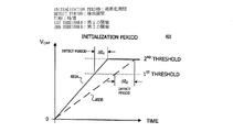
前記集積回路の前記初期化期間中に前記多機能キャパシタを充電するステップと、
前記多機能キャパシタの電圧が第1の値から第2の値に変化する時間期間を計測する
ステップとを備える、請求項1に記載の方法。 - 前記多機能キャパシタの前記電圧が前記第1の値から前記第2の値に変化する前記時間期間を計測するステップは、前記時間期間中に前記多機能キャパシタの前記電圧を高めるために所定の電流で前記多機能キャパシタを充電するステップを備える、請求項2に記載の方法。
- 前記多機能キャパシタの前記電圧が前記第1の値から前記第2の値に変化する前記時間期間を計測するステップは、前記時間期間中に前記多機能キャパシタの前記電圧を低くするために所定の電流で前記多機能キャパシタを放電するステップを備える、請求項2に記載の方法。
- 前記集積回路の前記パラメータ/モードを選択するステップは、前記多機能キャパシタの前記電圧が前記第1の値から前記第2の値に変化する計測された前記時間期間に応じて前記集積回路の前記パラメータ/モードを選択するステップを備える、請求項2に記載の方法。
- 前記集積回路を動作させるステップは、電源装置の入力から前記電源装置の出力へのエ
ネルギーの伝達を前記集積回路で調整するステップを備える、請求項1に記載の方法。 - 電源装置であって、
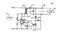
電源装置の入力と出力との間に結合されるエネルギー伝達素子と、
前記エネルギー伝達素子の入力に結合されるスイッチと、
前記スイッチの切替を制御して前記電源装置の前記入力から前記電源装置の前記出力へのエネルギー伝達を調整するように前記スイッチに結合されるコントローラと、
前記コントローラに結合される多機能キャパシタとを備え、
前記コントローラは、前記コントローラの初期化期間中に前記多機能キャパシタの容量値を推定し、推定された前記容量値に応じて前記コントローラのパラメータ/モードを設定し、前記コントローラを動作させるための電力を提供するために前記初期化期間の後に前記多機能キャパシタからバイアス電流を受け取る、電源装置。 - 前記コントローラは、
前記多機能キャパシタからの信号を計測するように結合される閾値検出及びタイミング回路と、
前記多機能キャパシタからの計測された前記信号に応じて前記コントローラの前記パラメータ/モードを選択するように前記閾値検出及びタイミング回路に結合される選択回路とを備える、請求項7に記載の電源装置。 - 前記閾値検出及びタイミング回路によって計測された前記信号は、前記多機能キャパシタの両端の電圧が第1の電圧から第2の電圧に変化する時間を備える、請求項8に記載の電源装置。
- 前記コントローラは、前記時間の計測に応じて前記コントローラの前記パラメータ/モードを設定するように結合される、請求項9に記載の電源装置。
- 前記第1の電圧は前記第2の電圧よりも大きい、請求項9に記載の電源装置。
- 電源装置の集積制御回路であって、
電源装置のキャパシタに結合されることになる端子と、
時間期間中に前記キャパシタの容量値を決定するように前記端子に結合される閾値検出及びタイミング回路と、
前記容量値に応じて前記時間期間中に集積回路の複数のパラメータ/モードの1つを決定するように前記閾値検出及びタイミング回路に結合されるパラメータ/モード選択回路とを備え、
前記集積制御回路は、前記時間期間が終了した後に前記集積回路を動作させるための電力を提供するために前記キャパシタから前記端子においてバイアス電流を選択的に受け取る、集積制御回路。 - 前記キャパシタは、前記集積制御回路の電源デカップリング機能を提供する、請求項12に記載の集積制御回路。
- 前記キャパシタは、前記集積制御回路のループ補償機能を提供する、請求項12に記載の集積制御回路。
- 前記端子は第1の端子であり、
前記時間期間中に前記パラメータ/モード選択回路によって決定される前記パラメータ/モードは、前記集積回路の第2の端子と第3の端子との間に結合されるスイッチにおいてピーク電流制限レベルを備える、請求項12に記載の集積制御回路。 - 前記キャパシタは前記第1の端子と前記第3の端子との間に結合されることになる、請求項15に記載の集積制御回路。
- 前記時間期間中に前記パラメータ/モード選択回路によって決定される前記パラメータ/モードは、前記集積回路の動作周波数を備える、請求項12に記載の集積制御回路。
- 前記集積制御回路の前記動作周波数は、前記集積回路の最大動作周波数である、請求項17に記載の集積制御回路。
- 前記端子に結合され、前記時間期間中に前記端子に結合される前記キャパシタを充電するための調整回路を更に備える、請求項12に記載の集積制御回路。
- 前記調整回路は、所定の電流で前記キャパシタを充電するための電流源を備える、請求項19に記載の集積制御回路。
- 前記時間期間中に前記キャパシタ内の電荷を低減するように結合される放電回路を更に備える、請求項19に記載の集積制御回路。
- 前記閾値検出及びタイミング回路は、前記端子における電圧が第1の電圧から第2の電圧に変化する時間の計測に応じて前記キャパシタの前記容量値を決定する、請求項12に記載の集積制御回路。
- 前記第1の電圧は前記第2の電圧よりも小さい、請求項22に記載の集積制御回路。
- 電源装置の集積制御回路であって、
電源装置のフィードバックループのキャパシタに結合されることになる端子と、
時間期間中に前記キャパシタの容量値を決定するように前記端子に結合される閾値検出及びタイミング回路と、
前記容量値に応じて前記時間期間中に集積回路の複数のパラメータ/モードの1つを決定するように前記閾値検出及びタイミング回路に結合されるパラメータ/モード選択回路とを備え、
前記集積制御回路は、前記時間期間が終了した後に前記キャパシタから前記端子においてフィードバックループ補償を受け取る、集積制御回路。 - 前記端子は第1の端子であり、
前記時間期間中に前記パラメータ/モード選択回路によって決定される前記パラメータ/モードは、前記集積回路の第2の端子と第3の端子との間に結合されるスイッチにおいてピーク電流制限レベルを備える、請求項24に記載の集積制御回路。 - 前記キャパシタは前記第1の端子と前記第3の端子との間に結合されることになる、請求項25に記載の集積制御回路。
- 前記時間期間中に前記パラメータ/モード選択回路によって決定される前記パラメータ/モードは、前記集積回路の動作周波数を備える、請求項24に記載の集積制御回路。
- 前記端子に結合され、前記時間期間中に所定の電流で前記キャパシタを充電するための電流源をさらに備える、請求項24に記載の集積制御回路。
- 前記時間期間中に前記キャパシタ内の電荷を低減するように結合される放電回路を更に
備える、請求項28に記載の集積制御回路。 - 前記閾値検出及びタイミング回路は、前記端子における電圧が第1の電圧から第2の電圧に変化する時間の計測に応じて前記キャパシタの前記容量値を決定する、請求項24に記載の集積制御回路。
Applications Claiming Priority (2)
| Application Number | Priority Date | Filing Date | Title |
|---|---|---|---|
| US11/213,252 | 2005-08-26 | ||
| US11/213,252 US7425834B2 (en) | 2005-08-26 | 2005-08-26 | Method and apparatus to select a parameter/mode based on a time measurement |
Related Child Applications (1)
| Application Number | Title | Priority Date | Filing Date |
|---|---|---|---|
| JP2012253113A Division JP5632441B2 (ja) | 2005-08-26 | 2012-11-19 | 集積制御回路 |
Publications (3)
| Publication Number | Publication Date |
|---|---|
| JP2007073954A JP2007073954A (ja) | 2007-03-22 |
| JP2007073954A5 JP2007073954A5 (ja) | 2009-10-01 |
| JP5221857B2 true JP5221857B2 (ja) | 2013-06-26 |
Family
ID=37451236
Family Applications (2)
| Application Number | Title | Priority Date | Filing Date |
|---|---|---|---|
| JP2006230382A Expired - Fee Related JP5221857B2 (ja) | 2005-08-26 | 2006-08-28 | 時間計測に基づきパラメータ/モードを選択する方法及び装置 |
| JP2012253113A Expired - Fee Related JP5632441B2 (ja) | 2005-08-26 | 2012-11-19 | 集積制御回路 |
Family Applications After (1)
| Application Number | Title | Priority Date | Filing Date |
|---|---|---|---|
| JP2012253113A Expired - Fee Related JP5632441B2 (ja) | 2005-08-26 | 2012-11-19 | 集積制御回路 |
Country Status (4)
| Country | Link |
|---|---|
| US (3) | US7425834B2 (ja) |
| EP (1) | EP1758234A3 (ja) |
| JP (2) | JP5221857B2 (ja) |
| CN (2) | CN102790529B (ja) |
Families Citing this family (25)
| Publication number | Priority date | Publication date | Assignee | Title |
|---|---|---|---|---|
| US7453709B2 (en) * | 2005-07-08 | 2008-11-18 | Power Integrations, Inc. | Method and apparatus for increasing the power capability of a power supply |
| US7425834B2 (en) * | 2005-08-26 | 2008-09-16 | Power Integrations, Inc. | Method and apparatus to select a parameter/mode based on a time measurement |
| JP5018781B2 (ja) * | 2006-09-29 | 2012-09-05 | 日本電気株式会社 | 信号選択装置、回路修正装置、回路シミュレータ、回路エミュレータ、信号選択方法およびプログラム |
| US7502236B2 (en) | 2006-10-04 | 2009-03-10 | Power Integrations, Inc. | Power supply controller responsive to a feedforward signal |
| US7518885B2 (en) * | 2006-10-04 | 2009-04-14 | Power Integrations, Inc. | Method and apparatus for a control circuit with multiple operation modes |
| US7576528B2 (en) * | 2006-10-04 | 2009-08-18 | Power Integrations, Inc. | Control circuit responsive to an impedance |
| GB0722519D0 (en) * | 2007-11-16 | 2007-12-27 | Univ Strathclyde | Active network management |
| US8116106B2 (en) * | 2008-09-19 | 2012-02-14 | Power Integrations, Inc. | Method and apparatus to select a parameter/mode based on a measurement during an initialization period |
| WO2010104172A1 (ja) * | 2009-03-13 | 2010-09-16 | 富士電機システムズ株式会社 | スイッチング電源装置、集積回路およびスイッチング電源装置の動作状態設定方法 |
| CN101562397B (zh) * | 2009-05-27 | 2014-02-12 | 成都芯源系统有限公司 | 基于第三绕组检测的双模式恒电流控制方法及其电路 |
| JP5170117B2 (ja) | 2010-01-18 | 2013-03-27 | 株式会社村田製作所 | スイッチング制御回路及びスイッチング電源装置 |
| US8098503B2 (en) * | 2010-02-09 | 2012-01-17 | Power Integrations, Inc. | Method and apparatus to control a power converter having a low loop bandwidth |
| WO2011129185A1 (ja) | 2010-04-16 | 2011-10-20 | 株式会社村田製作所 | スイッチング制御回路及びスイッチング電源装置 |
| WO2011155246A1 (ja) | 2010-06-10 | 2011-12-15 | 株式会社村田製作所 | スイッチング制御回路及びスイッチング電源装置 |
| JP5488274B2 (ja) | 2010-07-08 | 2014-05-14 | 富士電機株式会社 | 半導体集積回路およびスイッチング電源装置 |
| CN102971953B (zh) | 2010-07-26 | 2015-07-01 | 株式会社村田制作所 | 开关控制电路及开关电源装置 |
| JP5633535B2 (ja) * | 2012-04-16 | 2014-12-03 | 株式会社村田製作所 | スイッチング制御回路及びスイッチング電源装置 |
| CN103474963A (zh) * | 2013-09-13 | 2013-12-25 | 上海斐讯数据通信技术有限公司 | 开关电源输出过压保护电路 |
| US10056834B2 (en) * | 2015-09-17 | 2018-08-21 | Infineon Technologies Austria Ag | Output capacitance calculation and control in a power supply |
| US10088854B2 (en) * | 2016-09-15 | 2018-10-02 | Power Integrations, Inc. | Modulating jitter frequency as switching frequency approaches jitter frequency |
| US10651844B2 (en) * | 2018-06-15 | 2020-05-12 | Texas Instruments Incorporated | Multiple chip synchronization via single pin monitoring of an external timing capacitor |
| US11128224B2 (en) * | 2018-07-30 | 2021-09-21 | Texas Instruments Incorporated | Methods and apparatus for adaptive synchronous rectifier control |
| US11418121B2 (en) | 2019-12-30 | 2022-08-16 | Power Integrations, Inc | Auxiliary converter to provide operating power for a controller |
| US11258369B2 (en) | 2020-02-19 | 2022-02-22 | Power Integrations, Inc. | Inductive charging circuit to provide operative power for a controller |
| CN116400175B (zh) * | 2023-02-14 | 2024-02-02 | 山东电工电气集团数字科技有限公司 | 一种电力变压器线圈绝缘在线监测装置及方法 |
Family Cites Families (44)
| Publication number | Priority date | Publication date | Assignee | Title |
|---|---|---|---|---|
| US4823070A (en) | 1986-11-18 | 1989-04-18 | Linear Technology Corporation | Switching voltage regulator circuit |
| US5287086A (en) * | 1990-01-02 | 1994-02-15 | Raptor, Inc. | Proximity detection system and oscillator |
| DE69314079T2 (de) * | 1992-04-03 | 1998-03-26 | Jeol Ltd | Stromversorgung mit Speicherkondensator |
| US5313381A (en) | 1992-09-01 | 1994-05-17 | Power Integrations, Inc. | Three-terminal switched mode power supply integrated circuit |
| US5585733A (en) * | 1992-09-10 | 1996-12-17 | David Sarnoff Research Center | Capacitive sensor and method of measuring changes in capacitance |
| US5335162A (en) | 1993-01-15 | 1994-08-02 | Toko America, Inc. | Primary side controller for regulated power converters |
| US5576628A (en) * | 1994-09-30 | 1996-11-19 | Telcom Semiconductor, Inc. | Method and apparatus to measure capacitance |
| JPH1014097A (ja) | 1996-06-18 | 1998-01-16 | Hitachi Ltd | 電力変換器のコンデンサ容量判定装置 |
| US5864473A (en) | 1996-07-03 | 1999-01-26 | Operating Technical Electronics, Inc. | Dual stage AC to DC switching power supply with high voltage, low current intermediate DC and low voltage, high current regulated DC output |
| JP3753492B2 (ja) * | 1997-01-29 | 2006-03-08 | ローム株式会社 | 電源監視ic及び電池パック |
| US5859768A (en) | 1997-06-04 | 1999-01-12 | Motorola, Inc. | Power conversion integrated circuit and method for programming |
| JPH1132431A (ja) * | 1997-07-10 | 1999-02-02 | Citizen Watch Co Ltd | パワーオンリセット回路 |
| US5812383A (en) * | 1997-07-31 | 1998-09-22 | Philips Electronics North North America Corporation | Low power stand-by for switched-mode power supply circuit with burst mode operation |
| DE19805927A1 (de) | 1998-02-13 | 1999-10-28 | Thomson Brandt Gmbh | Schaltnetzteil |
| US6147883A (en) | 1998-11-16 | 2000-11-14 | Power Integrations, Inc. | Output feedback and under-voltage detection |
| US6462971B1 (en) | 1999-09-24 | 2002-10-08 | Power Integrations, Inc. | Method and apparatus providing a multi-function terminal for a power supply controller |
| US6388853B1 (en) | 1999-09-28 | 2002-05-14 | Power Integrations, Inc. | Method and apparatus providing final test and trimming for a power supply controller |
| JP3475887B2 (ja) * | 2000-01-11 | 2003-12-10 | 株式会社村田製作所 | スイッチング電源装置 |
| US6339338B1 (en) * | 2000-01-18 | 2002-01-15 | Formfactor, Inc. | Apparatus for reducing power supply noise in an integrated circuit |
| US6657455B2 (en) | 2000-01-18 | 2003-12-02 | Formfactor, Inc. | Predictive, adaptive power supply for an integrated circuit under test |
| JP3391774B2 (ja) | 2000-10-20 | 2003-03-31 | Smk株式会社 | 間欠動作型スイッチング電源回路 |
| JP4846107B2 (ja) | 2001-02-23 | 2011-12-28 | セミコンダクター・コンポーネンツ・インダストリーズ・リミテッド・ライアビリティ・カンパニー | 電源制御器およびその構成 |
| JP4849723B2 (ja) | 2001-02-23 | 2012-01-11 | 大亜真空株式会社 | 圧力測定装置 |
| GB2374135A (en) * | 2001-04-02 | 2002-10-09 | Autoflame Eng Ltd | Pressurised steam boilers and their control |
| JP2003152083A (ja) * | 2001-11-09 | 2003-05-23 | Hitachi Ltd | 半導体集積回路 |
| JP3816396B2 (ja) | 2001-12-05 | 2006-08-30 | Tdk株式会社 | スイッチング電源装置 |
| US7112978B1 (en) * | 2002-04-16 | 2006-09-26 | Transmeta Corporation | Frequency specific closed loop feedback control of integrated circuits |
| JP3610964B2 (ja) * | 2002-05-13 | 2005-01-19 | 松下電器産業株式会社 | スイッチング電源装置 |
| DE10224354C1 (de) * | 2002-05-29 | 2003-10-02 | Siemens Metering Ag Zug | Schaltungsanordnung und Verfahren zur Kompensation von Änderungen eines Übertragungsfaktors einer Magnetfeldsensoranordnung |
| US6788074B2 (en) * | 2002-06-21 | 2004-09-07 | Texas Instruments Incorporated | System and method for using a capacitance measurement to monitor the manufacture of a semiconductor |
| JP4183551B2 (ja) | 2003-04-28 | 2008-11-19 | 富士通株式会社 | 半導体集積回路内電圧変動波形測定装置および電圧変動波形測定機能を有する半導体集積回路 |
| US7170381B2 (en) | 2003-07-09 | 2007-01-30 | Power Integrations, Inc. | Method and apparatus for transferring energy in a power converter circuit |
| US7055387B2 (en) * | 2003-07-25 | 2006-06-06 | The Charles Stark Draper Laboratory, Inc. | Apparatus for and method of sensing a measured input |
| US7157813B2 (en) | 2003-10-03 | 2007-01-02 | Power Integrations, Inc. | Method and apparatus for mode selection for high voltage integrated circuits |
| US7005855B2 (en) * | 2003-12-17 | 2006-02-28 | Visteon Global Technologies, Inc. | Device to provide a regulated power supply for in-cylinder ionization detection by using the ignition coil fly back energy and two-stage regulation |
| US7173402B2 (en) | 2004-02-25 | 2007-02-06 | O2 Micro, Inc. | Low dropout voltage regulator |
| US7148697B2 (en) * | 2004-06-04 | 2006-12-12 | Doljack Frank A | System and method for measuring electrical characteristics of a capacitor |
| US7002398B2 (en) | 2004-07-08 | 2006-02-21 | Power Integrations, Inc. | Method and apparatus for controlling a circuit with a high voltage sense device |
| JP4485337B2 (ja) | 2004-12-08 | 2010-06-23 | 株式会社日立製作所 | 電流検出回路、電源制御回路、電源装置、電源システム、および電子装置 |
| US7339359B2 (en) | 2005-03-18 | 2008-03-04 | Fairchild Semiconductor Corporation | Terminal for multiple functions in a power supply |
| US7310048B2 (en) | 2005-05-04 | 2007-12-18 | Power Integrations, Inc. | Method and apparatus for sensing a current in a circuit |
| US7245510B2 (en) | 2005-07-07 | 2007-07-17 | Power Integrations, Inc. | Method and apparatus for conditional response to a fault condition in a switching power supply |
| US7425834B2 (en) | 2005-08-26 | 2008-09-16 | Power Integrations, Inc. | Method and apparatus to select a parameter/mode based on a time measurement |
| US8116106B2 (en) | 2008-09-19 | 2012-02-14 | Power Integrations, Inc. | Method and apparatus to select a parameter/mode based on a measurement during an initialization period |
-
2005
- 2005-08-26 US US11/213,252 patent/US7425834B2/en active Active
-
2006
- 2006-08-25 CN CN201210203493.XA patent/CN102790529B/zh not_active Expired - Fee Related
- 2006-08-25 CN CN2006101463769A patent/CN101039071B/zh active Active
- 2006-08-25 EP EP06254462A patent/EP1758234A3/en not_active Withdrawn
- 2006-08-28 JP JP2006230382A patent/JP5221857B2/ja not_active Expired - Fee Related
-
2008
- 2008-07-31 US US12/183,931 patent/US7804305B2/en not_active Expired - Fee Related
-
2010
- 2010-08-24 US US12/862,654 patent/US8742771B2/en not_active Expired - Fee Related
-
2012
- 2012-11-19 JP JP2012253113A patent/JP5632441B2/ja not_active Expired - Fee Related
Also Published As
| Publication number | Publication date |
|---|---|
| CN102790529A (zh) | 2012-11-21 |
| JP2013055882A (ja) | 2013-03-21 |
| US20100321039A1 (en) | 2010-12-23 |
| EP1758234A3 (en) | 2010-03-03 |
| CN101039071A (zh) | 2007-09-19 |
| EP1758234A8 (en) | 2007-07-04 |
| US20070046294A1 (en) | 2007-03-01 |
| US8742771B2 (en) | 2014-06-03 |
| US20090021298A1 (en) | 2009-01-22 |
| JP5632441B2 (ja) | 2014-11-26 |
| CN101039071B (zh) | 2012-07-18 |
| CN102790529B (zh) | 2014-12-24 |
| US7804305B2 (en) | 2010-09-28 |
| JP2007073954A (ja) | 2007-03-22 |
| EP1758234A2 (en) | 2007-02-28 |
| US7425834B2 (en) | 2008-09-16 |
Similar Documents
| Publication | Publication Date | Title |
|---|---|---|
| JP5221857B2 (ja) | 時間計測に基づきパラメータ/モードを選択する方法及び装置 | |
| US11095226B2 (en) | Switching power supply device having failure protection function, and method for controlling the same | |
| US7116564B2 (en) | Switching power supply unit and semiconductor device for switching power supply | |
| KR101365873B1 (ko) | 파워 컨버터, 컨트롤러 ic 및 그 동작 방법 | |
| US8531163B2 (en) | Switching power supply device, integrated circuit, and switching power supply device operation condition setting method | |
| KR101055340B1 (ko) | 스위칭 레귤레이터 및 그 동작 제어 방법 | |
| US8427850B2 (en) | Switching power supply device with a switching control circuit | |
| JP6424644B2 (ja) | 電源制御用半導体装置 | |
| KR101739550B1 (ko) | 열 차단부, 이를 포함하는 스위치 제어부, 및 열 차단 보호 동작 제어 방법 | |
| US20080278134A1 (en) | Switching power supply device | |
| US7388763B2 (en) | Switching power supply | |
| JP5457117B2 (ja) | 集積回路、電源制御回路、方法、および電源 | |
| US20110002068A1 (en) | Switching regulator with fault protection and method thereof | |
| EP2164149A2 (en) | Charge controlling semiconductor integrated circuit | |
| US9106140B2 (en) | DC/DC converter | |
| JP4889421B2 (ja) | スイッチング電源装置、半導体装置、および制御方法 | |
| JP2011229279A (ja) | 充電制御装置 | |
| JP2021090234A (ja) | スイッチング制御回路、電源回路 |
Legal Events
| Date | Code | Title | Description |
|---|---|---|---|
| RD03 | Notification of appointment of power of attorney |
Free format text: JAPANESE INTERMEDIATE CODE: A7423 Effective date: 20090306 |
|
| A521 | Request for written amendment filed |
Free format text: JAPANESE INTERMEDIATE CODE: A821 Effective date: 20090501 |
|
| RD04 | Notification of resignation of power of attorney |
Free format text: JAPANESE INTERMEDIATE CODE: A7424 Effective date: 20090501 |
|
| A521 | Request for written amendment filed |
Free format text: JAPANESE INTERMEDIATE CODE: A523 Effective date: 20090814 |
|
| A621 | Written request for application examination |
Free format text: JAPANESE INTERMEDIATE CODE: A621 Effective date: 20090814 |
|
| A977 | Report on retrieval |
Free format text: JAPANESE INTERMEDIATE CODE: A971007 Effective date: 20120627 |
|
| A131 | Notification of reasons for refusal |
Free format text: JAPANESE INTERMEDIATE CODE: A131 Effective date: 20120821 |
|
| TRDD | Decision of grant or rejection written | ||
| A01 | Written decision to grant a patent or to grant a registration (utility model) |
Free format text: JAPANESE INTERMEDIATE CODE: A01 Effective date: 20130305 |
|
| A61 | First payment of annual fees (during grant procedure) |
Free format text: JAPANESE INTERMEDIATE CODE: A61 Effective date: 20130308 |
|
| FPAY | Renewal fee payment (event date is renewal date of database) |
Free format text: PAYMENT UNTIL: 20160315 Year of fee payment: 3 |
|
| R150 | Certificate of patent or registration of utility model |
Ref document number: 5221857 Country of ref document: JP Free format text: JAPANESE INTERMEDIATE CODE: R150 Free format text: JAPANESE INTERMEDIATE CODE: R150 |
|
| R250 | Receipt of annual fees |
Free format text: JAPANESE INTERMEDIATE CODE: R250 |
|
| R250 | Receipt of annual fees |
Free format text: JAPANESE INTERMEDIATE CODE: R250 |
|
| R250 | Receipt of annual fees |
Free format text: JAPANESE INTERMEDIATE CODE: R250 |
|
| R250 | Receipt of annual fees |
Free format text: JAPANESE INTERMEDIATE CODE: R250 |
|
| R250 | Receipt of annual fees |
Free format text: JAPANESE INTERMEDIATE CODE: R250 |
|
| LAPS | Cancellation because of no payment of annual fees |