JP5216468B2 - Vertical wall planting device and wall greening structure using this - Google Patents
Vertical wall planting device and wall greening structure using thisInfo
- Publication number
- JP5216468B2 JP5216468B2 JP2008204181A JP2008204181A JP5216468B2 JP 5216468 B2 JP5216468 B2 JP 5216468B2 JP 2008204181 A JP2008204181 A JP 2008204181A JP 2008204181 A JP2008204181 A JP 2008204181A JP 5216468 B2 JP5216468 B2 JP 5216468B2
- Authority
- JP
- Japan
- Prior art keywords
- plant
- wall
- concave space
- vegetation
- guide
- Prior art date
- Legal status (The legal status is an assumption and is not a legal conclusion. Google has not performed a legal analysis and makes no representation as to the accuracy of the status listed.)
- Expired - Fee Related
Links
Images


Description
本願発明は、建造物の壁面に沿って設置し、あるいは従来の街路樹に替えて街路の障壁として設置したり、また道路の分離帯として使用したり、さらには室内の区画壁として使用する等、さまざまな利用が可能な立壁状植栽装置と、これを用いた壁面緑化構造に関するものである。 The present invention is installed along the wall surface of a building, or installed as a street barrier instead of a conventional street tree, used as a road separation zone, and further used as an indoor partition wall, etc. The present invention relates to a standing wall-like planting device that can be used in various ways, and a wall surface greening structure using the device.
景観の向上といわゆるヒートアイランド現象の緩和策として建造物の屋上のみならず、今日では、壁面の緑化が提唱され、この壁面緑化のための様々な技術が提供されている。
壁面を緑化した場合、壁面からの日射熱の伝達量を軽減することで、建物内部に構成された居住空間の上昇温度を低減させることが可能となり、冷房負荷を軽減することが出来る。従って、建物の壁面緑化を実現することは、ヒートアイランド現象の緩和に寄与することになる。 また、壁面の緑化は無機質な壁面をヒトの眼に優しい景観に変えて自然の和みをあたえてくれる。
Today, not only the rooftop of buildings but also the greening of walls is being proposed as a measure to improve the landscape and the so-called heat island phenomenon, and various techniques for greening the walls are being offered.
When the wall surface is greened, by reducing the amount of solar heat transmitted from the wall surface, it is possible to reduce the rising temperature of the living space configured inside the building and to reduce the cooling load. Therefore, realizing wall greening of the building contributes to mitigating the heat island phenomenon. In addition, the greening of the wall gives a natural harmony by changing the inorganic wall surface to a human-friendly landscape.
壁面緑化技術の一例として、金属材などで形成された10cm程度の格子を有するネッ
トを壁面から離して取り付け、このネットに沿ってワイヤーなどを垂直方向に設けて蔓性植物を登坂させるようにしていた。この場合、植物の支持体が格子状ネットと直立するワイヤーであるため、登坂適性を有する植物には大幅な制限があった。
As an example of wall greening technology, a net having a lattice of about 10 cm formed of a metal material or the like is attached away from the wall surface, and a wire or the like is provided along the net in a vertical direction to climb a vine plant. It was. In this case, since the plant support is a wire that stands upright with the grid-like net, there was a significant limitation on plants having climbability.
また、他の壁面緑化技術として、壁面に、椰子殻繊維などのシートと金属ネットを組み合わせたマットを直接貼付し、蔓性植物や付着根タイプの植物を植生させるシステムもあるが、マットの耐久性、マットの彩色、壁面の通気性、壁面の汚染などの問題が発生する。 Another wall greening technology is a system that directly attaches a mat made of sheet metal such as coconut shell fiber and a metal net to the wall surface to vegetate vine plants and attached root type plants. Problems, such as property, mat coloration, wall air permeability, and wall surface contamination.
なお、本願発明と関連する技術が次の文献において開示されている。
本願発明は、植物の登坂、自立が容易で、広範囲にわたる植物に適応できる立壁状植栽装置とこれを用いた壁面緑化構造を提供して、設置の容易性、コストの低廉性、設置対象である壁面等の清浄性等を実現することを目的としている。 The present invention provides a standing wall-like planting device that is easy to climb up and stand by a plant, and can be applied to a wide range of plants, and a wall greening structure using the same, and is easy to install, low in cost, The purpose is to achieve cleanliness of certain wall surfaces.
本願発明は、植物の上方向への生育を幇助する植物伸長路と、植物伸長路の一側面ならびに複数の植物伸長路間に張設され植物の展張繁茂を可能とする植物支持壁とを具え、前記植物伸長路には植生による柱状部を、また前記植物支持壁には植生による立壁が形成されるようになっている立壁状植栽装置であって、前記植物伸長路は植物を囲繞しその進行方向を上方に収束する誘導壁を具えてなり、前記植物支持壁は格子又はメッシュ状その他の多孔体で構成され、前記誘導壁により上下方向に伸びる凹空間が形成されていて、この凹空間には付着根を有する常緑性の植生による柱状部が、また前記植物支持壁には蔓性の植物の繁茂展張により立壁が形成され、前記凹空間の内側面には植物根の付着を容易にするために粒体を含有する塗料の塗布により多数の凹凸部が形成されてなる立壁状植栽装置を提供して、上記従来の課題を解決しようとするものである。 The present invention comprises a plant extension path that supports the upward growth of plants, and a plant support wall that is stretched between one side of the plant extension path and a plurality of plant extension paths to enable the plant to grow and grow. The plant extending path is a standing wall-shaped planting device in which a columnar portion by vegetation is formed on the plant extending path, and a standing wall by vegetation is formed on the plant supporting wall, wherein the plant extending path surrounds the plant The plant support wall is composed of a lattice or mesh-like porous body, and a concave space extending in the vertical direction is formed by the guide wall. Columnar parts of evergreen vegetation with attached roots are formed in the space, and standing walls are formed on the plant support wall by the growth of vines, and plant roots are easily attached to the inner surface of the recessed space. Of paint containing granules to Provides a number of uneven portions is formed upright wall shaped planting device by a cloth, it is intended to solve the conventional problems described above.
また、上記段落0007の立壁状植栽装置において、前記誘導壁の両側端部には誘導壁内の植物の外部への進出を防止するための見切り縁部を形成するとともに植物支持壁の下部には、下端から所定高さを有する登攀防止部を形成し、この登攀防止部は植物支持壁を構成する格子又はメッシュ状その他の多孔体の各孔部を幼児の足先を係合できない程度の大きさに形成して、幼児の登攀を防止するように構成することがある。Moreover, in the standing wall-like planting apparatus of the above paragraph 0007, a parting edge for preventing the plant in the guide wall from entering the outside is formed at both side ends of the guide wall, and at the lower part of the plant support wall. Forms a climbing prevention part having a predetermined height from the lower end, and this climbing prevention part is such that each of the holes of a lattice or mesh-like porous body constituting the plant support wall cannot be engaged with an infant's foot. The size may be configured to prevent the infant from climbing.
さらに、上記段落0008の立壁状植栽装置において、前記凹空間には通気口を形成して空気の流通により植栽植物のいわゆる根焼けを防止するとともに、凹空間を形成する前記誘導壁の両端には植物伸長路内の植物を凹空間内に整然と植生させるためのフランジ部を設ける構成となすことがある。Furthermore, in the standing wall-like planting apparatus of the above paragraph 0008, both ends of the guide wall forming a concave space while forming a vent hole in the concave space to prevent so-called root burning of the planted plant by air circulation. In some cases, a flange portion is provided for ordering plants in the plant extension path to orderly vegetation in the concave space.
さらにまた、上記段落0008の立壁状植栽装置において、前記誘導壁は、その断面形状がコ字形状、半円形状又は半楕円形状のいずれかで構成することがある。Furthermore, in the standing wall-shaped planting apparatus according to paragraph 0008, the guide wall may be configured to have a U-shaped, semicircular or semi-elliptical cross section.
また、上記段落0008の立壁状植栽装置において、前記各誘導壁はその断面形状がコ字形状、半円形状又は半楕円形状のものの適宜組み合わせで配設した構成となすことがある。 Moreover, in the standing wall-shaped planting apparatus according to Paragraph 0008, each guide wall may have a configuration in which the cross-sectional shape is appropriately combined with a U shape, a semicircular shape, or a semielliptical shape .
本願発明はまた、建造物壁面に沿って立壁状植栽装置を構築してなる壁面緑化構造であって、植物の上方向への生育を幇助する植物伸長路と、植物伸長路の一側面ならびに複数の植物伸長路間に張設され植物の展張繁茂を可能とする植物支持壁とを具え、前記植物伸長路には植生による柱状部を、また前記植物支持壁には植生による立壁が形成されるようになっている立壁状植栽装置であって、前記植物伸長路は植物を囲繞しその進行方向を上方に収束する誘導壁を具えてなり、前記植物支持壁は格子又はメッシュ状その他の多孔体で構成され、前記誘導壁により上下方向に伸びる凹空間が形成されていて、この凹空間には付着根を有する常緑性の植生による柱状部が、また前記植物支持壁には蔓性の植物の繁茂展張により立壁が形成され、前記凹空間の内側面には植物根の付着を容易にするために粒体を含有する塗料の塗布により多数の凹凸部が形成されてなる壁面緑化構造を提供して、上記従来の課題を解決しようとするものである。The invention of the present application is also a wall surface greening structure formed by constructing a standing wall-like planting device along a building wall surface, a plant extension path that assists the upward growth of the plant, one side surface of the plant extension path, and A plant support wall that is stretched between a plurality of plant extension roads to enable the plant to grow and grow, and a columnar portion formed by vegetation is formed on the plant extension path, and a standing wall formed by vegetation is formed on the plant support wall. A vertical wall-like planting device, wherein the plant extension path comprises a guide wall that surrounds the plant and converges its traveling direction upward, and the plant support wall is a lattice or mesh-like or other It is composed of a porous body, and a concave space extending in the vertical direction is formed by the guide wall. In this concave space, a columnar portion made of evergreen vegetation having attached roots is formed. A standing wall is formed by the extension of the plant. A wall greening structure in which a large number of irregularities are formed on the inner surface of the concave space by applying a paint containing granules to facilitate the attachment of plant roots, thereby solving the above-mentioned conventional problems It is something to try.
また、上記段落0012の立壁状植栽装置において、前記誘導壁の両側端部には誘導壁内の植物の外部への進出を防止するための見切り縁部を形成するとともに植物支持壁の下部には、下端から所定高さを有する登攀防止部を形成し、この登攀防止部は植物支持壁を構成する格子又はメッシュ状その他の多孔体の各孔部を幼児の足先を係合できない程度の大きさに形成して、幼児の登攀を防止するように構成することがある。Moreover, in the standing wall-like planting apparatus of the above paragraph 0012, a parting edge for preventing the plant in the guide wall from entering the outside is formed at both side ends of the guide wall, and at the lower part of the plant support wall. Forms a climbing prevention part having a predetermined height from the lower end, and this climbing prevention part is such that each of the holes of a lattice or mesh-like porous body constituting the plant support wall cannot be engaged with an infant's foot. The size may be configured to prevent the infant from climbing.
さらに、上記段落0013の壁面緑化構造において、前記凹空間には通気口を形成して空気の流通により植栽植物のいわゆる根焼けを防止するとともに、凹空間を形成する前記誘導壁の両端には植物伸長路内の植物を凹空間内に整然と植生させるためのフランジ部を設ける構成となすことがある。Furthermore, in the wall greening structure of the above paragraph 0013, a vent is formed in the concave space to prevent so-called root burning of the planted plant by air circulation, and at both ends of the guide wall forming the concave space. There may be a configuration in which a flange portion is provided for orderly planting the plants in the plant extension path in the concave space.
また、上記段落0014の壁面緑化構造において、前記誘導壁は、その断面形状がコ字形状、半円形状又は半楕円形状のいずれかで構成することがある。 Also, in the green wall structure of the paragraph 0014, the guide wall is sometimes sectional shape is constituted by a U-shaped, or semicircular or semi-elliptical shape.
そして、上記段落0014の壁面緑化構造において、前記各誘導壁はその断面形状がコ字形状、半円形状又は半楕円形状のものの適宜組み合わせで配設する構成となすことがある。And in the wall surface greening structure of the above paragraph 0014, each guide wall may have a configuration in which the cross-sectional shape is appropriately combined with a U shape, a semicircular shape, or a semielliptical shape.
本願発明は、次のような効果を奏する。
(1) 建造物の内外において、迅速容易に壁面を緑化できる。
(2) 大掛かりな工事を要しないので設置コスト、管理コストあるいは撤去コストも低廉である。
(3) 本願発明では、立壁緑化面はその表裏において植物が繁茂しているので、衝立のような使用が可能であり、室内外での区画材として多方面に使用できる。
(4) 街路樹に替えてあるいは目印としてガードレール代わりに使用することもできる。
(5) 本願発明を、夏季の窓辺に設置することによりカーテン代わりに使用して暑熱を有効に遮断できる。
(6) 広い範囲の植物に対応できる。特に、従来技術では登攀できなかった蔓性植物、付着根植物を植栽することができる。
The present invention has the following effects.
(1) The wall surface can be greened quickly and easily inside and outside the building.
(2) Since large-scale construction is not required, installation cost, management cost or removal cost is low.
(3) In the present invention, the standing wall greening surface is planted on both sides, so it can be used like a partition, and can be used in many directions as a partition material indoors and outdoors.
(4) It can be used instead of a guardrail instead of a roadside tree or as a landmark.
(5) By installing the present invention on a window in summer, it can be used in place of a curtain to effectively block heat.
(6) Applicable to a wide range of plants. In particular, it is possible to plant vines and sticky root plants that could not be climbed by the prior art.
立壁状植栽装置において、植物伸長路としての植物誘導壁は金属材又は樹脂材で形成し、その断面形状は半円、半楕円形状、凹形状が好ましい。その形状において、両端壁部とこれに挟まれる壁部すなわち断面凹形状空間で植物を囲繞しその進行方向を上方に誘導する。 In the standing wall planting device, the plant guide wall as the plant extension path is formed of a metal material or a resin material, and the cross-sectional shape is preferably a semicircle, a semi-elliptical shape, or a concave shape. In that shape, the plant is surrounded by both end wall portions and the wall portions sandwiched between the wall portions, that is, the cross-sectional concave shape space, and the traveling direction thereof is guided upward.
立壁状植栽装置は、複数の植物伸長路を並立させ、この植物伸長路を構成する植物誘導壁の開口面側に植物支持壁を張設して構成されるが、この植物支持壁は、金属材または樹脂材によるネットで形成する。 植栽される植物は、ネットに絡み合って生育し、あるいは前記植物誘導壁とネットで囲繞される空間を情報に向かって伸長する。 The standing wall-shaped planting device is configured by juxtaposing a plurality of plant extension paths and extending a plant support wall on the opening surface side of the plant guide wall constituting the plant extension path. It is made of a net made of metal or resin material. The plant to be planted grows intertwined with the net, or extends toward the information in the space surrounded by the plant guide wall and the net.
この立壁状植栽装置に植栽する植物は、基本的にはつる植物が適している。つる植物は大きく分けて、巻きつる型植物と吸着型植物に分かれる。本願の立壁状植栽装置において、上下方向に立設される植物導路は植物を囲繞しその進行方向を上方に誘導する制御壁を有しおり、植物は四方の制御壁への当接を繰り返す結果、上方への進出を誘導されるので、植物の種類に特に限定されないが、植物導路の壁部や植物支持体への定着性の見地から、吸着型植物が好ましく、特に常緑性を有するヘデラ・カナリエンシスやヘデラ・へリックス等のヘデラ類が適しており、これらは耐暑性も高く屋内、屋外の設置に最も適している。 As a plant to be planted in this standing wall planting device, a vine plant is basically suitable. Vine plants can be broadly divided into winding vines and adsorption plants. In the standing wall-like planting device of the present application, the plant guide erected in the vertical direction has a control wall that surrounds the plant and guides its traveling direction upward, and the plant repeats contact with the control walls on all sides. As a result, since it is guided to advance upward, it is not particularly limited to the type of plant, but from the standpoint of the fixing property to the wall portion of the plant channel and the plant support, an adsorptive plant is preferable, and particularly has an evergreen nature. Hedera such as Hedera canariensis and Hedera helix are suitable, and they are highly heat resistant and are most suitable for indoor and outdoor installations.
上下方向に立設される植物伸長路としての植物誘導壁の内壁には前記植物特にヘデラ類の付着根の自着を容易にするため凹凸部を形成する。この凹凸部は、材料自体に凹凸部を形成しても良いが、内壁に粒体を含有する塗料を塗布して形成するのが、コスト上からも、また、多数の凹凸を容易に得られることからも好ましい。そして、植物誘導壁の内壁にはさらに、通気口を設けて、付着する植物の根焼けを防止するようにする。 An uneven portion is formed on the inner wall of the plant guide wall as a plant extension path erected in the vertical direction in order to facilitate self-adhesion of the attached root of the plant, particularly Hedera. Although this uneven part may form an uneven part in the material itself, it is easy to obtain a large number of uneven parts from the viewpoint of cost because it is formed by applying a paint containing granules on the inner wall. This is also preferable. Further, the inner wall of the plant guide wall is further provided with a vent so as to prevent root burning of the adhering plant.
本願に係る壁面緑化装置は、前記立壁状植栽装置を建造物の壁面に沿って設置して構成される。この際、植物伸長路の背面すなわち植物誘導壁の開口面の反対面は、建造物の外壁に直付けしてもよいが、外壁から離開させれば、通気性も確保でき外壁も汚れることがない。 また、幼児などが植物誘導壁の足を掛けて登って転落する事故を防止するために、植物誘導壁の下部に登攀防止部を形成し、この登攀防止部は植物支持壁を構成する格子又はメッシュ状その他の多孔体の各孔部を幼児の足先を係合できない程度の大きさに形成して、幼児の登攀を防止するようにする。 The wall surface greening apparatus according to the present application is configured by installing the standing wall-shaped planting apparatus along the wall surface of a building. At this time, the back surface of the plant extension path, that is, the surface opposite to the opening surface of the plant guide wall may be directly attached to the outer wall of the building, but if it is separated from the outer wall, the air permeability can be ensured and the outer wall can become dirty. Absent. In addition, in order to prevent an accident that an infant or the like climbs on the plant guide wall and falls, a climbing prevention part is formed in the lower part of the plant guide wall, and this climbing prevention part is a lattice or The holes of the mesh or other porous body are formed to a size that does not allow the infant's feet to engage with each other, thereby preventing the infant from climbing.
なお、立壁状植栽装置の植物伸長路には常緑性の吸着根タイプの植物を植栽する一方、植物支持壁には落葉性の蔓性植物を植栽するようにすれば、冬季の落葉時には植物支持壁において建物に日差しが得られるなどの効果がある。 In addition, planting the evergreen adsorbate root type plant on the plant extension path of the standing wall planting device, while planting the deciduous vine plant on the plant support wall, Sometimes, there is an effect that sunlight is obtained in the building on the plant support wall.
図面に基づいて本願発明の実施例を説明する。
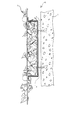
図1は、立壁状植栽装置Aの斜視図である。 図において、Aは立壁状植栽装置であり、この立壁状植栽装置Aは、植物の上方向への生育を幇助する植物伸長路1とこの植物伸長路1,1間に張設され植物の展張繁茂を可能とする植物支持壁2とを具えていて、前記植物伸長路には植生による柱状部を、また前記植物支持壁には植生による立壁が形成されるようになっている。前記植物伸長路1は植物を囲繞しその進行方向を上方に収束する誘導壁3を具えてなり、前記植物支持壁2は格子又はメッシュ状その他の多孔体で構成されていて、該実施例では金属材による格子状の多孔体となっている。そして、植物伸長路1における前記誘導壁3は、図2に示すように、断面コ字形状を有していて、上下方向に伸びる断面凹形状空間3aが形成され、この断面凹形状空間3aには、例えば、付着根を有する常緑性のヘデラなどが植生による柱状部が、また前記植物支持壁2にも、蔓性の植物の繁茂展張により立壁2aが形成されている。 なお、図2において、4は、前記誘導壁3の両側端部には誘導壁3内の植物の外部への進出を防止するために設けられた見切り縁部であり、これにより、特定の誘導壁3に植栽した植物の他への侵出が防止でき、植物相互の混生を防ぎ、植生の管理を容易にする。 また、図1に示すように、植物支持壁2の下部には、下端から所定高さを有する登攀防止部Fを形成し、この登攀防止部Fは植物支持壁を構成する格子又はメッシュ状その他の多孔体の各孔部を幼児の足先を係合できない程度の大きさに形成して、幼児の登攀を防止するようにする。 さらに、図2に示すように、植物伸長路3には常緑性の吸着根タイプの植物を植栽する一方、植物支持壁2には落葉性の蔓性植物を植栽して、落葉期には植物支持壁2において建物に日差しを得られるように構成する。
Embodiments of the present invention will be described with reference to the drawings.
FIG. 1 is a perspective view of a standing wall-shaped planting apparatus A. FIG. In the figure, A is a standing wall-like planting device, and this standing wall-like planting device A is a plant stretched between the
図3は、図1、2に示す前記誘導壁3の斜視図であり、前記断面凹形状空間3aの内側面には植物根の付着を容易にするために多数の凹凸部5が形成されており、この実施例では、前記凹凸部5は、粒体を含有する塗料を塗布して形成されている。さらに、前記断面凹形状空間3aには通気口6が形成され、空気の流通により植栽植物のいわゆる根焼けを防止するようになっている。
FIG. 3 is a perspective view of the
図4は、誘導壁3の他の実施例を示す図で、同図(a)は、断面形状が半円形のもの、同図(b)は、断面形状が半楕円形状のものを示している。 図5は、誘導壁3のさらに他の実施例を示す図でなお、この実施例で、フランジ部Jは内側に形成され、このため、植物伸長路1内の植物はその空間3a内に整然と植生される。
4A and 4B are diagrams showing another embodiment of the
図6は、本願発明にかかる壁面緑化構造の一実施例を示す横断面図である。 この壁面緑化構造Bは、建造物壁面7に沿って前述した実施例に係る立壁状植栽装置Aを構築してなるものである。 すなわち、壁面緑化構造Bにおいて、前記立壁状植栽装置Aは、壁面に取り付けられて植物の上方向への生育を幇助する植物伸長路1と、この植物伸長路間1に張設され植物の展張繁茂を可能とする植物支持壁2とを具え、前記植物伸長路1には植生による柱状部を、また前記植物支持壁には植生による立壁が形成されてなり、前記植物伸長路は1植物を囲繞しその進行方向を上方に収束教導する誘導壁3を具え、前記植物支持壁2は格子又はメッシュ状その他の多孔体で構成されている。
FIG. 6 is a cross-sectional view showing an embodiment of the wall surface greening structure according to the present invention. This wall greening structure B is constructed by building the standing wall-shaped planting apparatus A according to the above-described embodiment along the building wall 7. That is, in the wall surface greening structure B, the standing wall-shaped planting apparatus A is attached to the wall surface and extends between the
図6に示す壁面緑化構造Bでは、立壁状植栽装置Aはアンカーボルト8により、建造物壁面7との間に空間を設けて固定されているが、壁面に直付けすることもできる。 In the wall surface greening structure B shown in FIG. 6, the standing wall-shaped planting apparatus A is fixed with a space between the building wall surface 7 by the anchor bolts 8, but can be directly attached to the wall surface.
立壁状植栽装置Aは、植物を繁茂させてから所望の場所に設置してもよいし、予め所定の場所に設置し、その場所で植物の生育を待つようにしてもよく、ケース・バイ・ケースで対処することになる。 また生育させる植物としては、常緑型はカロライナジャスミン、ピグノニア・カプレオラータ、ムベ、テイカカズラ、ニシキテイカ、アメリカツルマサキ類から葉の形状、繁茂状態、匂い、耐候性、成長の速さ等を勘案して選択する。 植物がいわゆる吸着登攀タイプのものでない場合は、植物は前記植物支持壁2を寄る辺として生育することになる。 The standing wall-shaped planting device A may be installed in a desired place after the plant has grown, or may be installed in a predetermined place in advance and wait for the plant to grow.・ We will deal with cases. As for the plants to be grown, the evergreen type is selected from Carolina Jasmine, Pignonia Capreolata, Mube, Teika Kazura, Nishiki Teika, and American Crested Beetle taking into consideration the leaf shape, overgrowth state, odor, weather resistance, growth speed, etc. . When the plant is not of the so-called adsorption climbing type, the plant grows as a side approaching the plant support wall 2.
立壁状植栽装置Aは窓辺の日除けとして使用できることは勿論であるが、日光を完全に遮蔽してしまうことはなく木洩れ日的に光を通すうえ風通しも良好であるから、日差し、通気に微妙な条件を要する植物や動物の成育の場で使用することができる。 また、温泉等の露天風呂の目隠しなどにも最適であり、さらには、駐車場の区画に藻使用でき、その利用範囲は種々様々である。 Of course, the standing wall-shaped planting device A can be used as a sunshade on the windowsill, but it does not completely block the sunlight, it leaks through the trees, and it has good ventilation, so it is sensitive to sunlight and ventilation. It can be used in growing plants and animals that require conditions. It is also ideal for blinding open-air baths such as hot springs. Furthermore, it can be used as algae for parking lots, and its range of use varies.
A..............立壁状植栽装置
B..............壁面緑化構造
F..............登攀防止部
J..............フランジ部
1..............植物伸長路
2..............植物支持壁
3..............誘導壁
3a.............凹空間
4..............見切り縁部
5..............凹凸部
6..............通気口
A. . . . . . . . . . . . . . Vertical wall planting equipment B. . . . . . . . . . . . . . Wall greening structure . . . . . . . . . . . . . Climbing prevention department . . . . . . . . . . . . .
Claims (10)
Priority Applications (1)
| Application Number | Priority Date | Filing Date | Title |
|---|---|---|---|
| JP2008204181A JP5216468B2 (en) | 2008-08-07 | 2008-08-07 | Vertical wall planting device and wall greening structure using this |
Applications Claiming Priority (1)
| Application Number | Priority Date | Filing Date | Title |
|---|---|---|---|
| JP2008204181A JP5216468B2 (en) | 2008-08-07 | 2008-08-07 | Vertical wall planting device and wall greening structure using this |
Publications (3)
| Publication Number | Publication Date |
|---|---|
| JP2010035512A JP2010035512A (en) | 2010-02-18 |
| JP2010035512A5 JP2010035512A5 (en) | 2010-09-02 |
| JP5216468B2 true JP5216468B2 (en) | 2013-06-19 |
Family
ID=42008697
Family Applications (1)
| Application Number | Title | Priority Date | Filing Date |
|---|---|---|---|
| JP2008204181A Expired - Fee Related JP5216468B2 (en) | 2008-08-07 | 2008-08-07 | Vertical wall planting device and wall greening structure using this |
Country Status (1)
| Country | Link |
|---|---|
| JP (1) | JP5216468B2 (en) |
Families Citing this family (4)
| Publication number | Priority date | Publication date | Assignee | Title |
|---|---|---|---|---|
| JP5783382B2 (en) * | 2012-11-21 | 2015-09-24 | フルタ鉄塔建設株式会社 | Multi-function fence and method for erecting a multi-function fence |
| JP6248450B2 (en) * | 2013-07-24 | 2017-12-20 | 株式会社大林組 | Vertical greening structure and vertical greening method |
| JP5960881B2 (en) * | 2014-11-25 | 2016-08-02 | 孝己 伊藤 | Support pillar for climbing plant and method for installing plant |
| CN113795143A (en) * | 2019-05-07 | 2021-12-14 | 大岛造园土木株式会社 | Method for cultivating attached sprawling plant and auxiliary cultivating device |
Family Cites Families (13)
| Publication number | Priority date | Publication date | Assignee | Title |
|---|---|---|---|---|
| JPS5457156U (en) * | 1977-09-29 | 1979-04-20 | ||
| JPH05316880A (en) * | 1992-05-15 | 1993-12-03 | Onoda Cement Co Ltd | Material for raising winder |
| JP3602948B2 (en) * | 1997-09-19 | 2004-12-15 | 日本道路公団 | Revegetation method and revegetation device using adsorptive vine plants |
| JP2001090176A (en) * | 1999-09-24 | 2001-04-03 | Daiwa House Ind Co Ltd | Seeding and planting structure of balcony |
| JP2003070361A (en) * | 2001-08-31 | 2003-03-11 | Tenchion:Kk | Vegetation gear and method of greening using the same |
| JP4480430B2 (en) * | 2004-03-18 | 2010-06-16 | トヨタT&S建設株式会社 | Precast concrete greening block |
| JP4492861B2 (en) * | 2004-09-07 | 2010-06-30 | 大島造園土木株式会社 | Greening panel |
| JP2006262741A (en) * | 2005-03-23 | 2006-10-05 | Matsushita Electric Ind Co Ltd | Greening device |
| JP4302655B2 (en) * | 2005-03-29 | 2009-07-29 | 中国電力株式会社 | Greening method of building and cultivation area for greening used therefor |
| JP2006345716A (en) * | 2005-06-13 | 2006-12-28 | Shimizu Corp | Greening structure of building |
| JP2007306862A (en) * | 2006-05-19 | 2007-11-29 | Toho Leo Co | Wall surface greening panel, and wall surface greening method of construction using the same |
| JP2008079519A (en) * | 2006-09-26 | 2008-04-10 | Misawa Homes Co Ltd | Wall-surface greening structure |
| JP5448294B2 (en) * | 2006-11-17 | 2014-03-19 | 田島ルーフィング株式会社 | Standing wall planting equipment and standing wall planting structure |
-
2008
- 2008-08-07 JP JP2008204181A patent/JP5216468B2/en not_active Expired - Fee Related
Also Published As
| Publication number | Publication date |
|---|---|
| JP2010035512A (en) | 2010-02-18 |
Similar Documents
| Publication | Publication Date | Title |
|---|---|---|
| JP4472774B1 (en) | Vertical wall planting device and wall greening structure using this | |
| JP2006262712A (en) | Greening structure and greening method | |
| JP2009528827A (en) | Vertical planting system | |
| JP5216468B2 (en) | Vertical wall planting device and wall greening structure using this | |
| JP2010035512A5 (en) | ||
| JP2007215516A (en) | Wall surface greening structure | |
| JP5448294B2 (en) | Standing wall planting equipment and standing wall planting structure | |
| US20170273254A1 (en) | A multi-stacking decorative flowerpot unit | |
| JP5191721B2 (en) | Wall greening structure | |
| JP2008125389A5 (en) | ||
| KR101399110B1 (en) | ecology column assembly | |
| JP2015149970A (en) | Vine plant cultivation device | |
| KR102167311B1 (en) | Tunnel house type ginseng cultivation facility | |
| JP5042930B2 (en) | Veranda greening method and greening device | |
| JP3609401B2 (en) | Plant unit, plant storage method in plant unit | |
| JP2011041533A (en) | Panel-attached cultivation container and method for greening building | |
| JP4568684B2 (en) | Vertical wall planting equipment | |
| JP3831713B2 (en) | Climbing guide for vine plants on the wall of a house | |
| JP2004097144A (en) | Panel member for plant culture and plant culture apparatus | |
| JP3109861U (en) | Vegetation planting equipment with support net | |
| JP4326550B2 (en) | Countermeasures against strong winds by raising soil platform and raising soil platform | |
| JP2007189948A5 (en) | ||
| JP4866032B2 (en) | Tree planting structure | |
| JP5261329B2 (en) | Vine plant growing equipment | |
| JPH09140267A (en) | Climbing guide for vine plant installed at wall of house |
Legal Events
| Date | Code | Title | Description |
|---|---|---|---|
| A621 | Written request for application examination |
Free format text: JAPANESE INTERMEDIATE CODE: A621 Effective date: 20100126 |
|
| A521 | Request for written amendment filed |
Free format text: JAPANESE INTERMEDIATE CODE: A523 Effective date: 20100217 |
|
| A521 | Request for written amendment filed |
Free format text: JAPANESE INTERMEDIATE CODE: A523 Effective date: 20100716 |
|
| A977 | Report on retrieval |
Free format text: JAPANESE INTERMEDIATE CODE: A971007 Effective date: 20111129 |
|
| A131 | Notification of reasons for refusal |
Free format text: JAPANESE INTERMEDIATE CODE: A131 Effective date: 20120221 |
|
| A521 | Request for written amendment filed |
Free format text: JAPANESE INTERMEDIATE CODE: A523 Effective date: 20120417 |
|
| TRDD | Decision of grant or rejection written | ||
| A01 | Written decision to grant a patent or to grant a registration (utility model) |
Free format text: JAPANESE INTERMEDIATE CODE: A01 Effective date: 20130205 |
|
| A61 | First payment of annual fees (during grant procedure) |
Free format text: JAPANESE INTERMEDIATE CODE: A61 Effective date: 20130304 |
|
| R150 | Certificate of patent or registration of utility model |
Free format text: JAPANESE INTERMEDIATE CODE: R150 |
|
| FPAY | Renewal fee payment (event date is renewal date of database) |
Free format text: PAYMENT UNTIL: 20160308 Year of fee payment: 3 |
|
| LAPS | Cancellation because of no payment of annual fees |