JP5180959B2 - 燃料噴射システム - Google Patents
燃料噴射システム Download PDFInfo
- Publication number
- JP5180959B2 JP5180959B2 JP2009521331A JP2009521331A JP5180959B2 JP 5180959 B2 JP5180959 B2 JP 5180959B2 JP 2009521331 A JP2009521331 A JP 2009521331A JP 2009521331 A JP2009521331 A JP 2009521331A JP 5180959 B2 JP5180959 B2 JP 5180959B2
- Authority
- JP
- Japan
- Prior art keywords
- fuel
- injector
- pump
- fuel injection
- injection system
- Prior art date
- Legal status (The legal status is an assumption and is not a legal conclusion. Google has not performed a legal analysis and makes no representation as to the accuracy of the status listed.)
- Active
Links
- 239000000446 fuel Substances 0.000 title claims abstract description 351
- 238000002347 injection Methods 0.000 title claims abstract description 109
- 239000007924 injection Substances 0.000 title claims abstract description 109
- 238000004891 communication Methods 0.000 claims abstract description 17
- 238000002485 combustion reaction Methods 0.000 claims abstract description 4
- 230000033001 locomotion Effects 0.000 claims description 12
- 238000011144 upstream manufacturing Methods 0.000 claims description 4
- 238000005086 pumping Methods 0.000 abstract description 34
- 230000008901 benefit Effects 0.000 description 22
- 238000004519 manufacturing process Methods 0.000 description 6
- 238000012986 modification Methods 0.000 description 6
- 230000004048 modification Effects 0.000 description 6
- 230000007246 mechanism Effects 0.000 description 5
- 230000000694 effects Effects 0.000 description 4
- 238000000034 method Methods 0.000 description 4
- 238000009434 installation Methods 0.000 description 3
- 230000009471 action Effects 0.000 description 2
- 230000001174 ascending effect Effects 0.000 description 2
- 230000009286 beneficial effect Effects 0.000 description 2
- 238000010586 diagram Methods 0.000 description 2
- 238000005516 engineering process Methods 0.000 description 2
- KJFBVJALEQWJBS-XUXIUFHCSA-N maribavir Chemical compound CC(C)NC1=NC2=CC(Cl)=C(Cl)C=C2N1[C@H]1O[C@@H](CO)[C@H](O)[C@@H]1O KJFBVJALEQWJBS-XUXIUFHCSA-N 0.000 description 2
- 230000001133 acceleration Effects 0.000 description 1
- 230000002411 adverse Effects 0.000 description 1
- 230000002238 attenuated effect Effects 0.000 description 1
- 230000005540 biological transmission Effects 0.000 description 1
- 230000008859 change Effects 0.000 description 1
- 230000007423 decrease Effects 0.000 description 1
- 230000001419 dependent effect Effects 0.000 description 1
- 239000012530 fluid Substances 0.000 description 1
- 239000012528 membrane Substances 0.000 description 1
- 230000008569 process Effects 0.000 description 1
Images


Classifications
-
- F—MECHANICAL ENGINEERING; LIGHTING; HEATING; WEAPONS; BLASTING
- F02—COMBUSTION ENGINES; HOT-GAS OR COMBUSTION-PRODUCT ENGINE PLANTS
- F02M—SUPPLYING COMBUSTION ENGINES IN GENERAL WITH COMBUSTIBLE MIXTURES OR CONSTITUENTS THEREOF
- F02M57/00—Fuel-injectors combined or associated with other devices
- F02M57/02—Injectors structurally combined with fuel-injection pumps
- F02M57/022—Injectors structurally combined with fuel-injection pumps characterised by the pump drive
- F02M57/023—Injectors structurally combined with fuel-injection pumps characterised by the pump drive mechanical
-
- F—MECHANICAL ENGINEERING; LIGHTING; HEATING; WEAPONS; BLASTING
- F02—COMBUSTION ENGINES; HOT-GAS OR COMBUSTION-PRODUCT ENGINE PLANTS
- F02M—SUPPLYING COMBUSTION ENGINES IN GENERAL WITH COMBUSTIBLE MIXTURES OR CONSTITUENTS THEREOF
- F02M55/00—Fuel-injection apparatus characterised by their fuel conduits or their venting means; Arrangements of conduits between fuel tank and pump F02M37/00
- F02M55/04—Means for damping vibrations or pressure fluctuations in injection pump inlets or outlets
-
- F—MECHANICAL ENGINEERING; LIGHTING; HEATING; WEAPONS; BLASTING
- F02—COMBUSTION ENGINES; HOT-GAS OR COMBUSTION-PRODUCT ENGINE PLANTS
- F02M—SUPPLYING COMBUSTION ENGINES IN GENERAL WITH COMBUSTIBLE MIXTURES OR CONSTITUENTS THEREOF
- F02M59/00—Pumps specially adapted for fuel-injection and not provided for in groups F02M39/00 -F02M57/00, e.g. rotary cylinder-block type of pumps
- F02M59/20—Varying fuel delivery in quantity or timing
- F02M59/36—Varying fuel delivery in quantity or timing by variably-timed valves controlling fuel passages to pumping elements or overflow passages
- F02M59/366—Valves being actuated electrically
-
- F—MECHANICAL ENGINEERING; LIGHTING; HEATING; WEAPONS; BLASTING
- F02—COMBUSTION ENGINES; HOT-GAS OR COMBUSTION-PRODUCT ENGINE PLANTS
- F02M—SUPPLYING COMBUSTION ENGINES IN GENERAL WITH COMBUSTIBLE MIXTURES OR CONSTITUENTS THEREOF
- F02M63/00—Other fuel-injection apparatus having pertinent characteristics not provided for in groups F02M39/00 - F02M57/00 or F02M67/00; Details, component parts, or accessories of fuel-injection apparatus, not provided for in, or of interest apart from, the apparatus of groups F02M39/00 - F02M61/00 or F02M67/00; Combination of fuel pump with other devices, e.g. lubricating oil pump
- F02M63/0003—Fuel-injection apparatus having a cyclically-operated valve for connecting a pressure source, e.g. constant pressure pump or accumulator, to an injection valve held closed mechanically, e.g. by springs, and automatically opened by fuel pressure
- F02M63/0007—Fuel-injection apparatus having a cyclically-operated valve for connecting a pressure source, e.g. constant pressure pump or accumulator, to an injection valve held closed mechanically, e.g. by springs, and automatically opened by fuel pressure using electrically actuated valves
-
- F—MECHANICAL ENGINEERING; LIGHTING; HEATING; WEAPONS; BLASTING
- F02—COMBUSTION ENGINES; HOT-GAS OR COMBUSTION-PRODUCT ENGINE PLANTS
- F02M—SUPPLYING COMBUSTION ENGINES IN GENERAL WITH COMBUSTIBLE MIXTURES OR CONSTITUENTS THEREOF
- F02M63/00—Other fuel-injection apparatus having pertinent characteristics not provided for in groups F02M39/00 - F02M57/00 or F02M67/00; Details, component parts, or accessories of fuel-injection apparatus, not provided for in, or of interest apart from, the apparatus of groups F02M39/00 - F02M61/00 or F02M67/00; Combination of fuel pump with other devices, e.g. lubricating oil pump
- F02M63/02—Fuel-injection apparatus having several injectors fed by a common pumping element, or having several pumping elements feeding a common injector; Fuel-injection apparatus having provisions for cutting-out pumps, pumping elements, or injectors; Fuel-injection apparatus having provisions for variably interconnecting pumping elements and injectors alternatively
- F02M63/0225—Fuel-injection apparatus having a common rail feeding several injectors ; Means for varying pressure in common rails; Pumps feeding common rails
- F02M63/0265—Pumps feeding common rails
- F02M63/027—More than one high pressure pump feeding a single common rail
Description
既知のハイブリッド型コモンレール−EUIシステムに勝る更なる利点は、ポンプ室と絞り弁が、ポンピングストロークの殆どの期間中、高圧燃料源(コモンレール)から切り離されるため、(例えば、プランジャー内径部及び絞り弁を介した)高圧燃料の漏出が低減されることである。
別の例として、システムは、燃料通路から燃料を受け取り、中を通して燃料を噴射器まで送るための、噴射器への供給通路を備えており、同構成では、絞りは供給通路と燃料通路との相互接続部間近の上流側に設置されている。
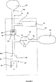
図2の燃料噴射システムは、噴射器流入通路42を経由して燃料が供給される噴射器40を含んでいる。噴射器流入通路42は、一端44aが、コモンレール46の形態をしたアキュミュレータ容積部と連通している燃料通路44から、燃料を受け取る。当業者には理解頂けるように、コモンレールという語句は、限定を課すことを意図しているのではなく、細長い(即ち、或る長さのパイプ)形状、円筒形状、球形状、又は他のどの様な形状であろうと関わりなく、燃料を貯めておくためのあらゆる容積部を記述するのに使われている。
使用時、ポンププランジャー48は、エンジンカムシャフト72によって、プランジャー48が内径部50から引き出されてポンプ室52の容積が拡張する戻りストロークと、ポンププランジャー48が内径部50の中へ進められポンプ室52の容積が減少するポンピングストロークから成るポンピングサイクルを行うように駆動される。プランジャー戻りストロークの開始時(即ち、ポンピングストロークの終了直後)には、ポンププランジャー48は、そのストロークの最上位置にあると言え、ポンプ室容積は最小になっており、また、戻りストロークの終了時(即ち、ポンピングストローク開始直前)には、ポンププランジャー48は、そのストロークの最下位置にあると言え、ポンプ室容積は最大になっている。
燃料噴射事象が燃料ポンプから独立しているため、燃料をエンジンサイクル当たり数回の割で吸入することが可能である。従って、幾つかの実施形態では、カムは、エンジン回転当たり2又はそれ以上のポンピングストロークを提供できるように多ローブカムであってもよい。その様な多ローブカムは、適切には2つ、3つ、又は4つのローブ、更に適切には2つ又は3つのローブ、最適には2つのローブを備えていてもよい。
Claims (15)
- 内燃機関の燃料噴射システムにおいて、
ハウジングユニット(38)内に配置されている第1燃料噴射器(40)と、
前記第1燃料噴射器(40)に燃料を供給するためのアキュミュレータ容積部(46)と、
使用時、第1ポンプ室(52)内に燃料の昇圧を生じさせるように駆動されるポンププランジャー(48)を備えている第1燃料ポンプ装置(68)と、
前記第1ポンプ室(52)に流入する燃料の流れを制御する働きをする第1絞り弁(66)と、
前記第1ポンプ室(52)と前記アキュミュレータ容積部(46)の間に連通を提供している第1燃料通路(44)と、
前記第1ポンプ室(52)と前記アキュミュレータ容積部(46)の間の前記第1燃料通路(44)に設置された第1逆止め弁(54)と、を備えており、
前記第1燃料噴射器(40)は、前記第1逆止め弁(54)と前記アキュミュレータ容積部(46)の間の或る位置で前記第1燃料通路(44)と連通しており、前記第1燃料噴射器(40)と前記アキュミュレータ容積部(46)の間の燃料通路(42、44)には、燃料の流れを制御又は阻止する役目を果たす液圧装置が含まれておらず、前記第1燃料噴射器は電子制御式噴射器(40)である、燃料噴射システム。 - 前記電子制御式噴射器(40)は、エンジンへの燃料噴射を制御するため、噴射器弁針の運動を制御するための三方向制御弁を含んでいる、請求項1に記載の燃料噴射システム。
- 前記電子制御式噴射器(40)は、エンジンへの燃料噴射を制御するため、噴射器弁針の運動を制御するための二方向制御弁を含んでいる、請求項1に記載の燃料噴射システム。
- 使用時、燃料噴射事象中、前記第1逆止め弁(54)は、前記第1燃料噴射器(40)が、燃料をアキュミュレータ容積部(46)から受け取り、前記第1ポンプ室(52)からは受け取らないように閉鎖される、請求項1から3の何れかに記載の燃料噴射システム。
- 第2燃料噴射器(40)と第2燃料通路(44)を更に備えており、前記第2燃料噴射器(40)は前記第2燃料通路(44)を介して前記アキュミュレータ容積部(46)と連通しており、前記第2燃料噴射器は電子制御式噴射器(40)である、請求項1から4の何れかに記載の燃料噴射システム。
- 前記第2燃料噴射器(40)と前記アキュミュレータ容積部(46)の間の連通は遮られていない、請求項5に記載の燃料噴射システム。
- 前記第2の電子制御式噴射器(40)は、エンジンへの燃料噴射を制御するため、噴射器弁針の運動を制御するための三方向制御弁を含んでいる、請求項5に記載の燃料噴射システム。
- 前記第2の電子制御式噴射器(40)は、エンジンへの燃料噴射を制御するため、噴射器弁針の運動を制御するための二方向制御弁を含んでいる、請求項5に記載の燃料噴射システム。
- 前記第2燃料噴射器(40)と前記アキュミュレータ容積部(46)の間に、少なくとも1つの絞り(70a、70b)を更に備えている、請求項5から8の何れかに記載の燃料噴射システム。
- 前記絞り(70a、70b)は、前記アキュミュレータ容積部の出口位置に設置されている、請求項9に記載の燃料噴射システム。
- 前記第2燃料通路(44)から燃料を受け取り、中を通して燃料を前記第2燃料噴射器(40)まで送るための、前記第2燃料噴射器(40)への第2供給通路(42)を更に備えており、前記絞り(70b)は、前記第2供給通路(42)と前記第2燃料通路(44)との相互接続部間近の上流側に設置されている、請求項9又は10に記載の燃料噴射システム。
- 使用時、前記第2燃料噴射器(40)は、燃料を、アキュミュレータ容積部(46)から受け取り、前記第1ポンプ室(52)からは受け取らない、請求項5から11の何れかに記載の燃料噴射システム。
- 複数の燃料噴射器(40)を備えており、前記燃料噴射器より少ない個数の燃料ポンプ装置(68)を備えている、請求項1から12の何れかに記載の燃料噴射システム。
- 最多6個までの燃料噴射器(40)と最多3個までの燃料ポンプ装置(68)を備えている、請求項13に記載の燃料噴射システム。
- 6個の燃料噴射器(40)と、
(i)1個の燃料ポンプ装置(68)又は
(ii)2個の燃料ポンプ装置(68)又は、
(iii)3個の燃料ポンプ装置(68)、を備えている、請求項13又は14に記載の燃料噴射システム。
Applications Claiming Priority (3)
| Application Number | Priority Date | Filing Date | Title |
|---|---|---|---|
| GB0614537.9 | 2006-07-21 | ||
| GBGB0614537.9A GB0614537D0 (en) | 2006-07-21 | 2006-07-21 | Fuel Injection System |
| PCT/GB2007/002795 WO2008009974A2 (en) | 2006-07-21 | 2007-07-20 | Fuel injection system |
Publications (2)
| Publication Number | Publication Date |
|---|---|
| JP2009544892A JP2009544892A (ja) | 2009-12-17 |
| JP5180959B2 true JP5180959B2 (ja) | 2013-04-10 |
Family
ID=36998511
Family Applications (1)
| Application Number | Title | Priority Date | Filing Date |
|---|---|---|---|
| JP2009521331A Active JP5180959B2 (ja) | 2006-07-21 | 2007-07-20 | 燃料噴射システム |
Country Status (7)
| Country | Link |
|---|---|
| US (1) | US8113175B2 (ja) |
| EP (1) | EP2044321B1 (ja) |
| JP (1) | JP5180959B2 (ja) |
| AT (1) | ATE507388T1 (ja) |
| DE (1) | DE602007014212D1 (ja) |
| GB (1) | GB0614537D0 (ja) |
| WO (1) | WO2008009974A2 (ja) |
Families Citing this family (8)
| Publication number | Priority date | Publication date | Assignee | Title |
|---|---|---|---|---|
| GB2460825A (en) | 2008-06-06 | 2009-12-16 | Delphi Tech Inc | Reagent dosing system |
| US9745937B2 (en) * | 2011-10-06 | 2017-08-29 | Toyota Jidosha Kabushiki Kaisha | Control device for internal combustion engine |
| US9429124B2 (en) | 2013-02-12 | 2016-08-30 | Ford Global Technologies, Llc | Direct injection fuel pump |
| US9599082B2 (en) * | 2013-02-12 | 2017-03-21 | Ford Global Technologies, Llc | Direct injection fuel pump |
| SE540744C2 (en) * | 2015-11-27 | 2018-10-30 | Scania Cv Ab | Method and system for determining pressure in a fuel accumulator tank of an engine |
| JP2017172561A (ja) * | 2016-03-25 | 2017-09-28 | 三桜工業株式会社 | 燃料分配管 |
| US10830194B2 (en) * | 2016-10-07 | 2020-11-10 | Caterpillar Inc. | Common rail fuel system having pump-accumulator injectors |
| US11536233B2 (en) | 2020-09-15 | 2022-12-27 | Delphi Technologies Ip Limited | Fuel system for an internal combustion engine |
Family Cites Families (10)
| Publication number | Priority date | Publication date | Assignee | Title |
|---|---|---|---|---|
| JPS56132456A (en) * | 1980-03-19 | 1981-10-16 | Mitsubishi Heavy Ind Ltd | Fuel injector |
| JPS6079157A (ja) * | 1983-10-05 | 1985-05-04 | Mitsubishi Heavy Ind Ltd | 燃料噴射装置 |
| JP3508359B2 (ja) | 1995-12-27 | 2004-03-22 | 株式会社デンソー | 蓄圧式燃料噴射装置 |
| US6494182B1 (en) * | 1999-02-17 | 2002-12-17 | Stanadyne Automotive Corp. | Self-regulating gasoline direct injection system |
| DE10132732A1 (de) * | 2001-07-05 | 2003-01-23 | Bosch Gmbh Robert | Kraftstoffeinspritzeinrichtung |
| EP1826397A3 (en) * | 2002-05-03 | 2009-08-05 | Delphi Technologies, Inc. | Fuel injection system |
| DE10301194A1 (de) * | 2003-01-15 | 2004-07-29 | Robert Bosch Gmbh | Kraftstoffeinspritzeinrichtung für eine Brennkraftmaschine |
| FR2871197B1 (fr) * | 2004-06-04 | 2006-07-28 | Renault V I Sa | Injecteur pompe |
| DE102004028886A1 (de) * | 2004-06-15 | 2006-01-05 | Robert Bosch Gmbh | Kraftstoffeinspritzeinrichtung |
| GB0621742D0 (en) * | 2006-10-31 | 2006-12-13 | Delphi Tech Inc | Fuel injection apparatus |
-
2006
- 2006-07-21 GB GBGB0614537.9A patent/GB0614537D0/en not_active Ceased
-
2007
- 2007-07-20 US US12/374,534 patent/US8113175B2/en active Active
- 2007-07-20 EP EP07789037A patent/EP2044321B1/en active Active
- 2007-07-20 DE DE602007014212T patent/DE602007014212D1/de active Active
- 2007-07-20 AT AT07789037T patent/ATE507388T1/de not_active IP Right Cessation
- 2007-07-20 JP JP2009521331A patent/JP5180959B2/ja active Active
- 2007-07-20 WO PCT/GB2007/002795 patent/WO2008009974A2/en active Application Filing
Also Published As
| Publication number | Publication date |
|---|---|
| WO2008009974A3 (en) | 2008-03-06 |
| EP2044321A2 (en) | 2009-04-08 |
| DE602007014212D1 (de) | 2011-06-09 |
| ATE507388T1 (de) | 2011-05-15 |
| WO2008009974A2 (en) | 2008-01-24 |
| GB0614537D0 (en) | 2006-08-30 |
| JP2009544892A (ja) | 2009-12-17 |
| US8113175B2 (en) | 2012-02-14 |
| EP2044321B1 (en) | 2011-04-27 |
| US20100050989A1 (en) | 2010-03-04 |
Similar Documents
| Publication | Publication Date | Title |
|---|---|---|
| JP5180959B2 (ja) | 燃料噴射システム | |
| US6439202B1 (en) | Hybrid electronically controlled unit injector fuel system | |
| US7574995B2 (en) | Fuel injection system | |
| US6447273B1 (en) | Variable-delivery high-pressure fuel pump | |
| EP1701031B1 (en) | An electromagnetic drive mechanism of a high-pressure fuel supply pump | |
| US6843053B2 (en) | Fuel system | |
| US6619263B1 (en) | Fuel injection system for an internal combustion engine | |
| US20070086899A1 (en) | Fuel system with variable discharge pump | |
| US8910882B2 (en) | Fuel injector having reduced armature cavity pressure | |
| JP2001193602A (ja) | 電子制御式ディーゼル燃料噴射システム | |
| US6675773B1 (en) | Method and apparatus for performing a fuel injection | |
| JP2009133306A (ja) | 燃料噴射システム | |
| JP3028471B2 (ja) | 燃料圧作動式エンジン圧縮ブレーキシステム | |
| JP4551399B2 (ja) | コモンレール燃料供給システム | |
| JP3887583B2 (ja) | 燃料噴射装置 | |
| JP2003113758A (ja) | 例えば直噴式である内燃機関を作動させるための、方法、コンピュータプログラム、開ループ制御及び/又は閉ループ制御式制御装置、ならびに燃料システム | |
| EP2241744A1 (en) | Common Rail Fuel Pump and Control Method for a Common Rail Fuel Pump | |
| JP3555588B2 (ja) | コモンレール式燃料噴射装置 | |
| JP2000073905A (ja) | 内燃機関用燃料噴射装置 | |
| RU2302550C2 (ru) | Система впрыска топлива (варианты) | |
| JP4861958B2 (ja) | 高圧燃料ポンプ | |
| JP3846917B2 (ja) | 燃料噴射装置 | |
| JP2001073900A (ja) | 内燃機関のための燃料噴射法および燃料噴射系 | |
| US20040099246A1 (en) | Fuel injector with multiple control valves | |
| US7451743B2 (en) | Fuel injection system with accumulator fill valve assembly |
Legal Events
| Date | Code | Title | Description |
|---|---|---|---|
| A711 | Notification of change in applicant |
Free format text: JAPANESE INTERMEDIATE CODE: A711 Effective date: 20100907 |
|
| A131 | Notification of reasons for refusal |
Free format text: JAPANESE INTERMEDIATE CODE: A131 Effective date: 20110602 |
|
| A601 | Written request for extension of time |
Free format text: JAPANESE INTERMEDIATE CODE: A601 Effective date: 20110831 |
|
| A602 | Written permission of extension of time |
Free format text: JAPANESE INTERMEDIATE CODE: A602 Effective date: 20110912 |
|
| A521 | Request for written amendment filed |
Free format text: JAPANESE INTERMEDIATE CODE: A523 Effective date: 20111201 |
|
| A02 | Decision of refusal |
Free format text: JAPANESE INTERMEDIATE CODE: A02 Effective date: 20120611 |
|
| A521 | Request for written amendment filed |
Free format text: JAPANESE INTERMEDIATE CODE: A523 Effective date: 20121010 |
|
| A911 | Transfer to examiner for re-examination before appeal (zenchi) |
Free format text: JAPANESE INTERMEDIATE CODE: A911 Effective date: 20121017 |
|
| TRDD | Decision of grant or rejection written | ||
| A01 | Written decision to grant a patent or to grant a registration (utility model) |
Free format text: JAPANESE INTERMEDIATE CODE: A01 Effective date: 20121214 |
|
| A61 | First payment of annual fees (during grant procedure) |
Free format text: JAPANESE INTERMEDIATE CODE: A61 Effective date: 20130111 |
|
| R150 | Certificate of patent or registration of utility model |
Ref document number: 5180959 Country of ref document: JP Free format text: JAPANESE INTERMEDIATE CODE: R150 |
|
| S111 | Request for change of ownership or part of ownership |
Free format text: JAPANESE INTERMEDIATE CODE: R313111 |
|
| R350 | Written notification of registration of transfer |
Free format text: JAPANESE INTERMEDIATE CODE: R350 |
|
| R250 | Receipt of annual fees |
Free format text: JAPANESE INTERMEDIATE CODE: R250 |
|
| R250 | Receipt of annual fees |
Free format text: JAPANESE INTERMEDIATE CODE: R250 |
|
| R250 | Receipt of annual fees |
Free format text: JAPANESE INTERMEDIATE CODE: R250 |
|
| R250 | Receipt of annual fees |
Free format text: JAPANESE INTERMEDIATE CODE: R250 |
|
| R250 | Receipt of annual fees |
Free format text: JAPANESE INTERMEDIATE CODE: R250 |
|
| R250 | Receipt of annual fees |
Free format text: JAPANESE INTERMEDIATE CODE: R250 |
|
| R250 | Receipt of annual fees |
Free format text: JAPANESE INTERMEDIATE CODE: R250 |
|
| R250 | Receipt of annual fees |
Free format text: JAPANESE INTERMEDIATE CODE: R250 |
|
| R250 | Receipt of annual fees |
Free format text: JAPANESE INTERMEDIATE CODE: R250 |