EP2241744A1 - Common Rail Fuel Pump and Control Method for a Common Rail Fuel Pump - Google Patents
Common Rail Fuel Pump and Control Method for a Common Rail Fuel Pump Download PDFInfo
- Publication number
- EP2241744A1 EP2241744A1 EP09157959A EP09157959A EP2241744A1 EP 2241744 A1 EP2241744 A1 EP 2241744A1 EP 09157959 A EP09157959 A EP 09157959A EP 09157959 A EP09157959 A EP 09157959A EP 2241744 A1 EP2241744 A1 EP 2241744A1
- Authority
- EP
- European Patent Office
- Prior art keywords
- pump
- fuel
- valve
- elements
- pumping
- Prior art date
- Legal status (The legal status is an assumption and is not a legal conclusion. Google has not performed a legal analysis and makes no representation as to the accuracy of the status listed.)
- Withdrawn
Links
Images


Classifications
-
- F—MECHANICAL ENGINEERING; LIGHTING; HEATING; WEAPONS; BLASTING
- F02—COMBUSTION ENGINES; HOT-GAS OR COMBUSTION-PRODUCT ENGINE PLANTS
- F02M—SUPPLYING COMBUSTION ENGINES IN GENERAL WITH COMBUSTIBLE MIXTURES OR CONSTITUENTS THEREOF
- F02M59/00—Pumps specially adapted for fuel-injection and not provided for in groups F02M39/00 -F02M57/00, e.g. rotary cylinder-block type of pumps
- F02M59/02—Pumps specially adapted for fuel-injection and not provided for in groups F02M39/00 -F02M57/00, e.g. rotary cylinder-block type of pumps of reciprocating-piston or reciprocating-cylinder type
-
- F—MECHANICAL ENGINEERING; LIGHTING; HEATING; WEAPONS; BLASTING
- F02—COMBUSTION ENGINES; HOT-GAS OR COMBUSTION-PRODUCT ENGINE PLANTS
- F02M—SUPPLYING COMBUSTION ENGINES IN GENERAL WITH COMBUSTIBLE MIXTURES OR CONSTITUENTS THEREOF
- F02M59/00—Pumps specially adapted for fuel-injection and not provided for in groups F02M39/00 -F02M57/00, e.g. rotary cylinder-block type of pumps
- F02M59/20—Varying fuel delivery in quantity or timing
- F02M59/36—Varying fuel delivery in quantity or timing by variably-timed valves controlling fuel passages to pumping elements or overflow passages
- F02M59/366—Valves being actuated electrically
- F02M59/368—Pump inlet valves being closed when actuated
-
- F—MECHANICAL ENGINEERING; LIGHTING; HEATING; WEAPONS; BLASTING
- F02—COMBUSTION ENGINES; HOT-GAS OR COMBUSTION-PRODUCT ENGINE PLANTS
- F02M—SUPPLYING COMBUSTION ENGINES IN GENERAL WITH COMBUSTIBLE MIXTURES OR CONSTITUENTS THEREOF
- F02M59/00—Pumps specially adapted for fuel-injection and not provided for in groups F02M39/00 -F02M57/00, e.g. rotary cylinder-block type of pumps
- F02M59/44—Details, components parts, or accessories not provided for in, or of interest apart from, the apparatus of groups F02M59/02 - F02M59/42; Pumps having transducers, e.g. to measure displacement of pump rack or piston
- F02M59/46—Valves
- F02M59/462—Delivery valves
-
- F—MECHANICAL ENGINEERING; LIGHTING; HEATING; WEAPONS; BLASTING
- F02—COMBUSTION ENGINES; HOT-GAS OR COMBUSTION-PRODUCT ENGINE PLANTS
- F02M—SUPPLYING COMBUSTION ENGINES IN GENERAL WITH COMBUSTIBLE MIXTURES OR CONSTITUENTS THEREOF
- F02M63/00—Other fuel-injection apparatus having pertinent characteristics not provided for in groups F02M39/00 - F02M57/00 or F02M67/00; Details, component parts, or accessories of fuel-injection apparatus, not provided for in, or of interest apart from, the apparatus of groups F02M39/00 - F02M61/00 or F02M67/00; Combination of fuel pump with other devices, e.g. lubricating oil pump
- F02M63/0012—Valves
- F02M63/0031—Valves characterized by the type of valves, e.g. special valve member details, valve seat details, valve housing details
- F02M63/0033—Lift valves, i.e. having a valve member that moves perpendicularly to the plane of the valve seat
- F02M63/0035—Poppet valves, i.e. having a mushroom-shaped valve member that moves perpendicularly to the plane of the valve seat
-
- F—MECHANICAL ENGINEERING; LIGHTING; HEATING; WEAPONS; BLASTING
- F02—COMBUSTION ENGINES; HOT-GAS OR COMBUSTION-PRODUCT ENGINE PLANTS
- F02M—SUPPLYING COMBUSTION ENGINES IN GENERAL WITH COMBUSTIBLE MIXTURES OR CONSTITUENTS THEREOF
- F02M63/00—Other fuel-injection apparatus having pertinent characteristics not provided for in groups F02M39/00 - F02M57/00 or F02M67/00; Details, component parts, or accessories of fuel-injection apparatus, not provided for in, or of interest apart from, the apparatus of groups F02M39/00 - F02M61/00 or F02M67/00; Combination of fuel pump with other devices, e.g. lubricating oil pump
- F02M63/0012—Valves
- F02M63/0031—Valves characterized by the type of valves, e.g. special valve member details, valve seat details, valve housing details
- F02M63/0054—Check valves
-
- F—MECHANICAL ENGINEERING; LIGHTING; HEATING; WEAPONS; BLASTING
- F02—COMBUSTION ENGINES; HOT-GAS OR COMBUSTION-PRODUCT ENGINE PLANTS
- F02D—CONTROLLING COMBUSTION ENGINES
- F02D41/00—Electrical control of supply of combustible mixture or its constituents
- F02D41/30—Controlling fuel injection
- F02D41/38—Controlling fuel injection of the high pressure type
- F02D41/3809—Common rail control systems
- F02D41/3836—Controlling the fuel pressure
- F02D41/3845—Controlling the fuel pressure by controlling the flow into the common rail, e.g. the amount of fuel pumped
-
- F—MECHANICAL ENGINEERING; LIGHTING; HEATING; WEAPONS; BLASTING
- F02—COMBUSTION ENGINES; HOT-GAS OR COMBUSTION-PRODUCT ENGINE PLANTS
- F02M—SUPPLYING COMBUSTION ENGINES IN GENERAL WITH COMBUSTIBLE MIXTURES OR CONSTITUENTS THEREOF
- F02M2200/00—Details of fuel-injection apparatus, not otherwise provided for
- F02M2200/50—Arrangements of springs for valves used in fuel injectors or fuel injection pumps
- F02M2200/502—Springs biasing the valve member to the open position
Definitions
- the present invention relates to a common rail fuel pump for use in a fuel injection system of an internal combustion engine.
- the invention also relates to a control method for such a pump.
- fuel is pressurised by means of a high-pressure fuel pump, which is supplied with fuel from a fuel tank by a low-pressure transfer pump.
- the high-pressure fuel pump comprises a main pump housing supporting multiple pump elements. Each pump element includes a plunger, which is driven in a reciprocating motion by a camshaft to generate high fuel pressure. Fuel at high pressure is then stored in a common fuel rail for delivery to fuel injectors.
- the pump elements typically have a maximum pumping capacity that is in excess of the fuel requirements for a steady-state operation of the engine. An excess pumping capacity is only required when the engine is operated under high loads and during transient engine conditions where it is necessary to rapidly raise the pressure in the common fuel rail. Additional pumping capacity may also be provided to allow for degradation of the pump elements over their operational life. Accordingly, the pump elements operate at less than full pumping capacity over a significant proportion of their operational life.
- a single inlet metering valve is used to meter the fuel entering the pump elements.
- Fuel in the pump elements becomes pressurised during a pumping stroke of a pump cycle.
- the provision of the inlet metering valve means that, throughout the operational range of the engine, the pumping duty of the high-pressure fuel pump is distributed equally between the pump elements, regardless of whether or not the pump elements are being operated at less than their maximum pumping capacity. Accordingly, the frequency with which each pump element is required to perform a pumping stroke is a maximum.
- Each pump element is subject to fatigue when a pumping stroke is carried out, and therefore the frequency with which a pump element performs a pumping stroke is directly related to its life cycle. Furthermore, it has been recognised that due to clearances between components of the pump elements, the pump elements are subject to high-pressure fuel leakages during the pumping stroke.
- the high-pressure fuel leakages represent a reduction in pump efficiency as the pressurised fuel is not entirely displaced to the common fuel rail.
- a control method for a high-pressure fuel pump comprising a plurality of pump elements, each of which comprises a plunger having a pumping stroke during which fuel within a pump chamber is pressurised and a filling stroke during which fuel is supplied to the pump chamber for pressurisation, and a valve for controlling fuel flow into and/or out of the pump chamber.
- the high-pressure fuel pump has a maximum pump capacity corresponding to all of the pump elements pumping at maximum capacity.
- the method further comprises reducing the pump capacity of the high-pressure fuel pump by reducing the pump duty of at least one of the pump elements to less than its maximum capacity.
- the control method may further comprise holding the valve of at least one of the pump elements in the open position throughout both the filling stroke and the pumping stroke so as to disable said pump element.
- control method further comprises, for a least one of the pump elements, holding the valve in a closed position throughout both the filling stroke and the pumping stroke so as to disable said pump element.
- the pumping duty of at least one of the pump elements is removed, meaning it is not exposed to a pressurising phase of the pumping stroke. Therefore, the frequency with which at least one of the pump elements is subject to a pumping stroke is reduced, along with the possibility of fatigue failure.
- the pump capacity of the high-pressure fuel pump is unevenly distributed across the pump elements.
- the overall pumping duty of the high-pressure fuel pump can be distributed and re-distributed over the pump elements, thereby reducing the frequency with which the pump elements are subject to a pressurising phase of the pumping stroke, thus reducing the possibility of fatigue failure.
- the pumping duty of the high-pressure fuel pump can be re-distributed so that it is provided by one pump element for one pumping stroke and by another pump element for a subsequent pumping stroke.
- the control method further comprises, for at least one of the pump elements, holding the valve in an open position during a filling stroke of the plunger to permit fuel to be supplied to the pump chamber, and holding the valve in the open position for one or more periods of a pumping stroke of the plunger so as to dispel a proportion of fuel that is supplied to the pump chamber during the filling stroke back through the valve.
- the one or more periods of the pumping stroke of one of the pump elements is different from that of the other elements.
- the valve for controlling fuel flow into and/or out of the pump chamber takes the form of a latching valve.
- a high-pressure fuel pump comprising a plurality of pump elements, each of which comprises a plunger having a pumping stroke during which fuel within a pump chamber is pressurised and a filling stroke during which fuel is supplied to the pump chamber for pressurisation, and a valve for controlling fuel flow into and/or out of the pump chamber.
- the high-pressure fuel pump has a maximum pump capacity corresponding to all of the pump elements pumping at maximum capacity.
- the high-pressure fuel pump further comprises means for reducing the pump capacity of the high-pressure fuel pump by reducing the pump duty of at least one of the pump elements to less than its maximum capacity.
- the valve for controlling fuel flow into and/or out of the pump chamber takes the form of a latching valve.
- the high-pressure fuel pump further comprises means for holding the valve of at least one of the pump elements in the open position throughout both the filling stroke and the pumping stroke so as to disable said pump element.
- the pumping duty of at least one of the pump elements is removed, meaning it is not exposed to a pressurising phase of the pumping stroke. Therefore, the frequency with which at least one of the pump elements is subject to a pumping stroke is reduced, along with the possibility of fatigue failure.
- the high-pressure fuel pump includes means for holding the valve of at least one of the pump elements in a closed position throughout both the filling stroke and the pumping stroke so as to disable said pump element.
- the high-pressure fuel pump further comprises a common pump-housing block, wherein the plurality of pump elements are housed within the common pump-housing block.
- the valve for controlling fuel flow into and/or out of the pump chamber is preferably a latching valve.
- the pump capacity of the high-pressure fuel pump is unevenly distributed across the pump elements.
- the overall pumping duty of the high-pressure fuel pump can be distributed and re-distributed over the pump elements, thereby reducing the frequency with which the pump elements are subject to a pressurising phase of a pumping stroke, thus reducing the possibility of fatigue failure.
- the high-pressure fuel pump further comprises, for at least one of the pump elements, means for holding the valve in an open position during a filling stroke of the plunger to permit fuel to be supplied to the pump chamber, and means for holding the valve in the open position for one or more periods of a pumping stroke of the plunger so as to dispel a proportion of fuel that is supplied to the pump chamber during the filling stroke back through the valve.
- the or each period of the pumping stroke for which the valve is held in the open position is different from the or each period of the pumping stroke of the other pump elements for which the valves of those elements are held open.
- a control method for a high-pressure fuel pump comprising a plurality of pump elements, each of which comprises a plunger for pressurising fuel within a pump chamber and a valve for controlling fuel delivery into and/or out of the pump chamber.
- the method further comprises holding the valve in an open position during a filling stroke of the plunger to permit fuel to be supplied to the pump chamber, and maintaining the valve in the open position for at least one selected stage of a pumping stroke of the plunger so as to dispel a proportion of fuel that is supplied to the pump chamber during the filling stroke back through the valve, and closing the valve during the pumping stroke, other than during the at least one selected stage, so as to permit pressurisation of the fuel within the pump chamber.
- the at least one selected stage includes that period of the pumping stroke for which the plunger either accelerates from and/or decelerates to zero velocity.
- the pump element During pressurisation of the fuel in the pump chamber, the pump element is subject to high-pressure fuel leakages due to clearances between, for example, the plunger and the pumping chamber, which reduce the pumping efficiency of the pump element.
- the overall velocity of the plunger is increased through said phase. Accordingly, the duration over which the pump element is subject to high-pressure fuel leakages is reduced, thereby leading to an increase in the pumping efficiency of the pump element.
- the at least one selected stage includes the initial and/or latter stages of the pumping stroke.
- a known high-pressure fuel pump of a common rail fuel system of a compression ignition internal combustion engine (referred to as the engine) has multiple pump elements operating in a phased cyclical manner.
- Each pump element is identical and, as shown in Figure 1 , comprises a plunger, which is used to pressurise fuel within the pump element for delivery to a fuel rail common to each of the other pump elements.
- the plungers are driven by means of a cam mounted on an engine driven shaft.
- the pump element 2 includes a pump chamber 6 and an inlet passage 4 to the pump chamber 6.
- the inlet passage 4 is in communication with a low-pressure transfer pump (not shown) usually via a single inlet metering valve (not shown).
- the transfer pump serves to supply fuel from a low pressure fuel reservoir (not shown) to the inlet passage 4.
- the inlet passage 4 is isolated from the pump chamber 6 by means of a hydraulically operated non-return inlet valve 8 (referred to as the inlet valve).
- the inlet valve 8 is biased into a closed position by means of a first spring 9 and fuel pressure within the pump chamber 6.
- a plunger 10 is housed within the pump chamber 6 and is driven, in a reciprocating motion, by a camshaft (not shown).
- the plunger 10 is in a bottom-dead-centre position when at a lowermost position (i.e. when the volume/capacity of the pump chamber 6 is a maximum) and in a top-dead-centre position when at an uppermost position (i.e. when the volume/capacity of the pump chamber 6 is a minimum).
- a pump cycle is said to have occurred when the plunger 10 has moved from the top-dead-centre position to the bottom-dead-centre position, and back to the top-dead-centre position.
- the inlet valve 8 responds automatically to the motion of the plunger 10: as the plunger 10 moves from the bottom-dead-centre position to the top-dead-centre position, the increasing pressure in the pump chamber 6, in combination with the biasing force of the first spring 9, forces the inlet valve 8 into the closed position. As the plunger 10 returns to the bottom-dead-centre position, the decreasing pressure in the pump chamber 6, in combination with the pressure of the fuel in the inlet passage 4, urges the inlet valve 8 into an open position, against the force of the first spring 9.
- An outlet passage 12 from the pump chamber 6 is isolated from the pump chamber 6 by means of a hydraulically operated non-return outlet valve 14 (referred to as the outlet valve).
- the outlet passage 12 is in direct communication with a common fuel rail (not shown), so that pressure in both is substantially equal.
- the common rail receives pressurised fuel from the outlet passage 12 from each pump element 2 of the pump.
- the outlet valve 14 is biased into a closed position by high pressure fuel in the common rail, acting in combination with a second spring 16. It will be appreciated that, in practice, the biasing forces provided by the first and second springs 9, 16 are relatively low and provide a much less significant force than the pressure of the fuel.
- the inlet valve 8 is caused to open, thereby permitting fuel delivery from the inlet passage 4 to the pump chamber 6.
- This part of the pump cycle is referred to as a filling stroke.
- the outlet valve 14 is biased into the closed position throughout the filling stroke due to the high pressure fuel in the common rail and the force from the second spring 16. Fuel delivery to the pump chamber 6 terminates at the end of the filling stroke, when the plunger 10 reaches the bottom-dead-centre position.
- the plunger 10 moves to the top-dead-centre position.
- This part of the pump cycle is referred to as a pumping stroke, during which the motion of the plunger 10 serves to increase the fuel pressure in the pump chamber 6.
- the fuel pressure in the pump chamber 6 can increase to several thousand atmospheres.
- the outlet valve 14 is caused to open to permit high pressure fuel delivery from the pump chamber 6 through the outlet passage 12 and, hence, to the common rail.
- the provision of the outlet valve 14 ensures that the high-pressure fuel remains trapped in the common rail and cannot return to the pump chamber 6. A point will be reached nearing a latter stage of the pumping stroke when the outlet valve 14 is caused to close under the high fuel pressure in the common rail, thus terminating the supply of fuel through the outlet passage 12.
- the pump element 2 receives and displaces a maximum amount of fuel, which corresponds to the maximum volume/capacity of the pump chamber 6. It has been recognised that maximum fuel displacement from the high-pressure fuel pump is necessary when, for example, the engine is operating under a high load or during transient engine conditions where it is necessary to rapidly increase the fuel pressure in the common rail.
- the inlet metering valve regulates the amount of fuel delivered by the transfer pump to the inlet passage 4 of the pumping element 2.
- the provision of the inlet metering valve means that the pumping duty of the high-pressure fuel pump is distributed substantially equally between the multiple pump elements.
- each pump element 2 completes a pumping cycle, or more particularly, a pumping stroke of a pumping cycle.
- the degree of fatigue a pump element 2 is subject to is dependent on the frequency with which it is subject to a pressurising phase and not the duration of the pressurising phase.
- the present invention improves on the above-described pump element 2 by replacing the inlet valve 8 with a valve that does not respond automatically to the motion of the plunger 10.
- the construction of the pump element 17 in the present invention is substantially the same as described previously, in terms of the inlet and outlet passages 4, 12, the plunger 10 and the outlet valve 14, but differs in a key respect.
- the inlet valve 8 of the known pump element 2 is replaced by an inlet metering valve in the form of a solenoid latching valve 18 (referred to as the latching valve 18) which is controlled by an Engine Control Unit (ECU).
- ECU Engine Control Unit
- the provision of the latching valve 18 means that the fuel displaced by the pump element 17 can be metered independently of the motion of the plunger 10, i.e. the latching valve 18 does not respond automatically to the motion of the plunger 10.
- the latching valve 18 includes an armature 20 coupled to a valve head 22 via a valve stem 24.
- the valve head 22 is engageable with a seating surface 26 defined at an inlet port 28 to the pump chamber 6, which communicates with the inlet passage 4.
- Activation of the latching valve 18 causes the valve head 22 of the latching valve 18 to move into engagement with the seating surface 26, thereby isolating the pump chamber 6 from the inlet passage 4.
- Deactivation of the latching valve 18 causes the valve head 22 of the latching valve 18 to move away from the seating surface 26, thus providing communication between the inlet passage 4 and the pump chamber 6.
- FIG 2 shows the pump element 17 during the filling stroke of the plunger 10: when the latching valve 18 is deactivated, fuel is supplied, by means of the transfer pump, to the pump chamber 6 through the inlet passage 4.
- the latching valve 18 is activated to move the valve head 22 into contact with the seating surface 26, thereby trapping the fuel in the pump chamber 6 and preventing further filling through the inlet passage 4.
- the outlet valve 14 remains closed (as shown in Figure 3 ).
- the fuel pressure in the pump chamber 6 is increased during the subsequent pumping stroke of the plunger 10 as it moves from the bottom-dead-centre position to the top-dead-centre position.
- the outlet valve 14 is caused to open. Pressurised fuel within the pump chamber 6 is therefore able to flow through the outlet passage 12 into the common rail. Once it has been activated, the latching valve 18 remains closed throughout the remainder of the pumping stroke.
- the pump cycle displaces a maximum amount of fuel, which corresponds to the maximum volume/capacity of the pump chamber 6. It will be appreciated that the maximum pump capacity of the pump is therefore achieved when all pump elements are operated in the aforementioned manner (i.e. maximum capacity).
- the latching valve 18 can be used to meter the amount of fuel displaced by the plunger 10 during the pumping stroke to precisely meet the demands of the engine at any given time.
- the pre-pumping phase is terminated when the latching valve 18 is activated, causing the valve head 22 of the latching valve 18 to contact the seating surface 26 of the pump chamber 6.
- the latching valve 18 is activated, fuel that remains trapped in the pump chamber 6 is pressurised under the motion of the plunger 10 moving to the top-dead-centre position. This phase of the pumping stroke is referred to as the "metering phase” or “pressurising phase".
- the latching valve 18 remains closed throughout the remainder of the pumping stroke.
- the outlet valve 14 is caused to open to permit high pressure fuel delivery from the pump chamber 6 through the outlet passage 12 and, hence, to the common rail.
- the capacity of the pump chamber 6, and hence the amount of fuel displaced by the plunger 10 can be selected according to the pumping requirements.
- the overall pumping duty of the high-pressure pump can be, evenly or unevenly, distributed over the pump elements collectively.
- the latching valve 18 can be controlled so as to decrease the leakage of fuel during the pumping stroke of the pump cycle.
- Known pump elements 2 are subject to high pressure fuel leakages during the pumping stroke due to clearances between, for example, the plunger 10 and the pump chamber 6, which reduce the pump efficiency of the pump element 2.
- it is desirable to minimise the duration of the pumping stroke by maximising the average speed of the plunger 10 during the pumping stroke.
- the shape of the cam driving the plunger 10 results in phases of the pumping stroke during which the plunger is subject to periods of substantial acceleration and deceleration.
- the plunger 10 accelerates from a zero velocity at the bottom-dead-centre position to a maximum velocity in a middle phase of the pumping stroke, and decelerates from the maximum velocity to a zero velocity at the top-dead-centre position. It will be appreciated that a significant proportion of the plunger's 10 acceleration and deceleration occurs in the initial and latter stages of the pumping stroke, respectively. Accordingly, the average speed of the plunger 10 in the initial and latter stages of the pumping stroke is relatively low compared to the maximum speed of the plunger 10.
- the full pumping stroke of the known pump element 2 occurs over, for example, a camshaft angle range of 120 degrees to 180 degrees i.e. the plunger 10 is at the bottom-dead-centre position at a camshaft angle of 120 degrees and is at the top-dead-centre position at a camshaft angle of 180 degrees.
- This camshaft angle range constitutes the pressurising phase of the pumping stroke of the pump element 2, and is inclusive of the initial and latter stages of the pumping stroke, during which the average speed of the plunger 10 is relatively low.
- the latching valve 18 is deactivated to allow the fuel to flow from the pump chamber 6 through the inlet passage 4 during the initial stage of the pumping stroke, and is only activated at a camshaft angle of, for example, 135 degrees.
- the cam shaft angle of 135 degrees represents the start of the pressurising phase of the pumping stroke.
- the pressurising phase excludes the initial stage of the pumping stroke during which the average speed of the plunger 10 is relatively low. Accordingly, the average speed of the plunger 10 during the pressurising phase is increased, when compared to the average speed of the plunger 10 of the known pump element 2 during the corresponding pressuring phase i.e. from a cam shaft angle of 120 degrees to 180 degrees. Therefore, the duration over which the pump element 17 of the present invention is subject to high-pressure fuel leakages is reduced and pump efficiency is increased.
- the overall pumping duty of the high-pressure fuel pump can be unevenly distributed over multiple pump elements by removing the pumping duty of one or more pump elements, subject to pumping requirements.
- the pumping duty of any one of the multiple pump elements can be removed by keeping the latching valve 18 of that pump element 17 deactivated throughout the pump cycle.
- fuel is supplied to the pump chamber 6 from the inlet passage 4 during the filling stroke. With the latching valve 18 still deactivated, continued movement of the plunger 10 through the pumping stroke causes the fuel in the pump chamber 6 to be displaced back through the inlet passage 4 into the transfer gallery.
- the fuel in the pump chamber 6 is prevented from being pressurised to a level sufficient to overcome the fuel pressure in the outlet passage 12 and the outlet valve 14 remains closed.
- the pumping duty of this pump element 17 is therefore effectively disabled.
- the pumping stroke is effectively a "spill" stroke where fuel is spilled back to the low-pressure fuel reservoir.
- the pumping duty of the pump element 17 can be removed by keeping the latching valve 18 activated throughout the entire pump cycle. Referring to Figures 7a to 7d , with the latching valve 18 activated, the valve head 22 of the latching valve 18 remains seated on the seating surface 26 of the pump chamber 6 and, in so doing, prevents the supply of fuel from the inlet passage 4 to the pump chamber 6. In this operation, the continued movement of the plunger 10 through the pump cycle serves only to draw a cavity in the pump chamber 6 during the filling stroke, and compress the cavity in the pumping stroke. Accordingly, the pumping duty of the pump element 17 is disabled.
- the third and the fourth modes of operation have the advantage of removing the pressurising phase of the pumping stroke of the pump element 17, thereby reducing the total number of pressurising phases that the pump element 17 is subjected to. Therefore, the possibility of fatigue failure is reduced.
- the fourth mode of operation offers a further benefit as the fuel is prevented from entering the pump chamber 6 and so the pump element 17 is not subject to any low-pressure pumping losses, for example at high plunger 10 speeds where energy is wasted as fuel in the pump chamber 6 is displaced back through the inlet passage 4 due to the pressure rise in overcoming flow restrictions across the valve 18.
- the latching valve may be replaced with a valve which can be opened against pressurised fuel in the pump chamber 6 so that it is possible to exclude both the initial and latter stages of the pumping stroke in order to further increase the average speed of the plunger 10 during the pressurising phase.
- a valve which can be opened against pressurised fuel in the pump chamber 6 so that it is possible to exclude both the initial and latter stages of the pumping stroke in order to further increase the average speed of the plunger 10 during the pressurising phase.
- the ECU controls independently the valves of each of the pump elements to meter the fuel flow into each pump chamber 6, whilst ensuring that the pump elements collectively displace a sufficient amount of fuel according to the pumping requirements.
- Removing, increasing or decreasing the pressurising phase of the pumping stroke of the pump elements means that the overall pumping duty of the high-pressure fuel pump can be evenly or unevenly distributed across the pump elements collectively.
- a high-pressure fuel pump comprising three pump elements, each the same as the known pumping element 2, will have three pumping strokes.
- the overall pumping duty of the high-pressure fuel pump is substantially evenly distributed over the three pump elements. Therefore, if the high-pressure fuel pump is required to deliver, for example, 660 mm 3 of pressurised fuel to the common rail, each pump element 2 must displace 220 mm 3 of fuel. Accordingly, each pump element 2 will be subject to a pressurising phase over the last 25 degrees of its pumping stroke.
- a high-pressure fuel pump comprising three pump elements 17 is required to displace 660 mm 3 of pressurised fuel to the common rail
- the second and third pump elements could be disabled and the first pump element 17 only could pressurise the fuel within the pump chamber 6 starting from a cam shaft angle of approximately 130 degrees.
- only the first pump element 17 is subject to a pressurising phase of the pumping stroke.
- the overall pumping duty of the high-pressure fuel pump could then subsequently be re-distributed over only the second pump element, for example, leaving the first and third pump elements disabled.
- the overall pump duty could be re-distributed over individual pump elements sequentially, thereby reducing the frequency with which the pump elements are subject to a pressurising phase and, hence, reducing the possibility of fatigue failure.
- a known high-pressure fuel pump having three pump elements 2 such as those in Figure 1 would use all three pump elements, each pumping over 25 degrees of the pump cycle (i.e. a total of 75 degrees per pump cycle during which the pump elements are exposed to a pressurising phase)
- in this example of the present invention only one of the pump elements 17 pumps for just 50 degrees per pump cycle.
- Re-distributing the overall pumping duty of the high-pressure fuel pump between pump elements avoids some of the pump elements becoming hotter than other pump elements, which is desirable to increase the durability of the pump elements.
Abstract
A control method for a high-pressure fuel pump comprising a plurality of pump elements (17), each of which comprises a plunger (10) having a pumping stroke during which fuel within a pump chamber (6) is pressurised and a filling stroke during which fuel is supplied to the pump chamber (6) for pressurisation, and a valve (18) for controlling fuel flow into and/or out of the pump chamber (6). The high-pressure fuel pump has a maximum pump capacity corresponding to all of the pump elements pumping at maximum capacity. The method comprises reducing the pump capacity of the high-pressure fuel pump by reducing the pump duty of at least one of the pump elements to less than its maximum capacity.
Description
- The present invention relates to a common rail fuel pump for use in a fuel injection system of an internal combustion engine. The invention also relates to a control method for such a pump.
- In common rail fuel systems for compression ignition internal combustion engines, fuel is pressurised by means of a high-pressure fuel pump, which is supplied with fuel from a fuel tank by a low-pressure transfer pump. Typically, the high-pressure fuel pump comprises a main pump housing supporting multiple pump elements. Each pump element includes a plunger, which is driven in a reciprocating motion by a camshaft to generate high fuel pressure. Fuel at high pressure is then stored in a common fuel rail for delivery to fuel injectors.
- The pump elements typically have a maximum pumping capacity that is in excess of the fuel requirements for a steady-state operation of the engine. An excess pumping capacity is only required when the engine is operated under high loads and during transient engine conditions where it is necessary to rapidly raise the pressure in the common fuel rail. Additional pumping capacity may also be provided to allow for degradation of the pump elements over their operational life. Accordingly, the pump elements operate at less than full pumping capacity over a significant proportion of their operational life.
- Typically, a single inlet metering valve is used to meter the fuel entering the pump elements. Fuel in the pump elements becomes pressurised during a pumping stroke of a pump cycle. The provision of the inlet metering valve means that, throughout the operational range of the engine, the pumping duty of the high-pressure fuel pump is distributed equally between the pump elements, regardless of whether or not the pump elements are being operated at less than their maximum pumping capacity. Accordingly, the frequency with which each pump element is required to perform a pumping stroke is a maximum.
- Each pump element is subject to fatigue when a pumping stroke is carried out, and therefore the frequency with which a pump element performs a pumping stroke is directly related to its life cycle. Furthermore, it has been recognised that due to clearances between components of the pump elements, the pump elements are subject to high-pressure fuel leakages during the pumping stroke. The high-pressure fuel leakages represent a reduction in pump efficiency as the pressurised fuel is not entirely displaced to the common fuel rail.
- It would be desirable to provide a high-pressure fuel pump and a control method for its pump elements that overcomes or at least alleviates at least one of the above-mentioned problems and disadvantages in the prior art.
- Thus, in accordance with a first aspect of the present invention there is provided a control method for a high-pressure fuel pump comprising a plurality of pump elements, each of which comprises a plunger having a pumping stroke during which fuel within a pump chamber is pressurised and a filling stroke during which fuel is supplied to the pump chamber for pressurisation, and a valve for controlling fuel flow into and/or out of the pump chamber. The high-pressure fuel pump has a maximum pump capacity corresponding to all of the pump elements pumping at maximum capacity. The method further comprises reducing the pump capacity of the high-pressure fuel pump by reducing the pump duty of at least one of the pump elements to less than its maximum capacity.
- The control method may further comprise holding the valve of at least one of the pump elements in the open position throughout both the filling stroke and the pumping stroke so as to disable said pump element.
- Alternatively, the control method further comprises, for a least one of the pump elements, holding the valve in a closed position throughout both the filling stroke and the pumping stroke so as to disable said pump element.
- Accordingly, the pumping duty of at least one of the pump elements is removed, meaning it is not exposed to a pressurising phase of the pumping stroke. Therefore, the frequency with which at least one of the pump elements is subject to a pumping stroke is reduced, along with the possibility of fatigue failure.
- In addition to the advantages gained from disabling at least one of the pump elements, holding the valve in a closed position throughout both the filling stroke and the pumping stroke has the added advantage of removing the possibility of low-pressure pumping losses, for example at high plunger speeds where energy is wasted as fuel in the pump chamber is displaced back through an inlet to the pump chamber due to the pressure rise in overcoming flow restrictions across the valve.
- Preferably, the pump capacity of the high-pressure fuel pump is unevenly distributed across the pump elements.
- During a steady state engine operation, for example, the overall pumping duty of the high-pressure fuel pump can be distributed and re-distributed over the pump elements, thereby reducing the frequency with which the pump elements are subject to a pressurising phase of the pumping stroke, thus reducing the possibility of fatigue failure.
- Furthermore, frequent re-distribution of the overall pumping duty of the high-pressure fuel pump over the individual pump elements avoids some of the pump elements becoming hotter than other pump elements, which is desirable to increase the durability of the pump elements. In other words, the pumping duty of the high-pressure fuel pump can be re-distributed so that it is provided by one pump element for one pumping stroke and by another pump element for a subsequent pumping stroke.
- The control method further comprises, for at least one of the pump elements, holding the valve in an open position during a filling stroke of the plunger to permit fuel to be supplied to the pump chamber, and holding the valve in the open position for one or more periods of a pumping stroke of the plunger so as to dispel a proportion of fuel that is supplied to the pump chamber during the filling stroke back through the valve. The one or more periods of the pumping stroke of one of the pump elements is different from that of the other elements.
- Preferably, the valve for controlling fuel flow into and/or out of the pump chamber takes the form of a latching valve.
- In accordance with a second aspect of the invention there is provided a high-pressure fuel pump comprising a plurality of pump elements, each of which comprises a plunger having a pumping stroke during which fuel within a pump chamber is pressurised and a filling stroke during which fuel is supplied to the pump chamber for pressurisation, and a valve for controlling fuel flow into and/or out of the pump chamber. The high-pressure fuel pump has a maximum pump capacity corresponding to all of the pump elements pumping at maximum capacity. The high-pressure fuel pump further comprises means for reducing the pump capacity of the high-pressure fuel pump by reducing the pump duty of at least one of the pump elements to less than its maximum capacity.
- Preferably, the valve for controlling fuel flow into and/or out of the pump chamber takes the form of a latching valve.
- In one embodiment the high-pressure fuel pump further comprises means for holding the valve of at least one of the pump elements in the open position throughout both the filling stroke and the pumping stroke so as to disable said pump element.
- Accordingly, the pumping duty of at least one of the pump elements is removed, meaning it is not exposed to a pressurising phase of the pumping stroke. Therefore, the frequency with which at least one of the pump elements is subject to a pumping stroke is reduced, along with the possibility of fatigue failure.
- Alternatively, in another embodiment, the high-pressure fuel pump includes means for holding the valve of at least one of the pump elements in a closed position throughout both the filling stroke and the pumping stroke so as to disable said pump element.
- Preferably, the high-pressure fuel pump further comprises a common pump-housing block, wherein the plurality of pump elements are housed within the common pump-housing block. The valve for controlling fuel flow into and/or out of the pump chamber is preferably a latching valve.
- Preferably, the pump capacity of the high-pressure fuel pump is unevenly distributed across the pump elements.
- During a steady state engine operation, for example, the overall pumping duty of the high-pressure fuel pump can be distributed and re-distributed over the pump elements, thereby reducing the frequency with which the pump elements are subject to a pressurising phase of a pumping stroke, thus reducing the possibility of fatigue failure.
- Furthermore, frequent re-distribution of the overall pumping duty of the high-pressure fuel pump over the individual pump elements avoids some of the pump elements becoming hotter than other pump elements, which is desirable to increase the durability of the pump elements.
- The high-pressure fuel pump further comprises, for at least one of the pump elements, means for holding the valve in an open position during a filling stroke of the plunger to permit fuel to be supplied to the pump chamber, and means for holding the valve in the open position for one or more periods of a pumping stroke of the plunger so as to dispel a proportion of fuel that is supplied to the pump chamber during the filling stroke back through the valve. For one of the pump elements, the or each period of the pumping stroke for which the valve is held in the open position is different from the or each period of the pumping stroke of the other pump elements for which the valves of those elements are held open.
- In accordance with a third aspect of the present invention there is provided a control method for a high-pressure fuel pump comprising a plurality of pump elements, each of which comprises a plunger for pressurising fuel within a pump chamber and a valve for controlling fuel delivery into and/or out of the pump chamber. The method further comprises holding the valve in an open position during a filling stroke of the plunger to permit fuel to be supplied to the pump chamber, and maintaining the valve in the open position for at least one selected stage of a pumping stroke of the plunger so as to dispel a proportion of fuel that is supplied to the pump chamber during the filling stroke back through the valve, and closing the valve during the pumping stroke, other than during the at least one selected stage, so as to permit pressurisation of the fuel within the pump chamber. The at least one selected stage includes that period of the pumping stroke for which the plunger either accelerates from and/or decelerates to zero velocity.
- During pressurisation of the fuel in the pump chamber, the pump element is subject to high-pressure fuel leakages due to clearances between, for example, the plunger and the pumping chamber, which reduce the pumping efficiency of the pump element. By excluding the at least one selected stage from the pressurising phase of the pumping stroke, the overall velocity of the plunger is increased through said phase. Accordingly, the duration over which the pump element is subject to high-pressure fuel leakages is reduced, thereby leading to an increase in the pumping efficiency of the pump element.
- Preferably, the at least one selected stage includes the initial and/or latter stages of the pumping stroke.
- It will be appreciated that preferred and/or optional feature of the first aspect of the invention may be incorporated within the second, third and fourth aspects of the invention, alone or in appropriate combination.
- The invention will now be described, by way of example only, with reference to the accompanying drawings, in which:
-
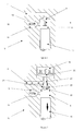
Figure 1 is a sectional view of a known pump element for use in a high-pressure fuel pump of a common rail fuel system; -
Figure 2 is a sectional view of a pump element of a high-pressure fuel pump of the present invention, including an inlet metering valve; -
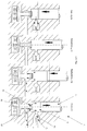
Figure 3 is a sectional view of the pump element ofFigure 2 , operating during an initial stage of a pressurising phase of a pumping stroke; -
Figures 4a to 4d are sectional views of the pump element ofFigure 3 , illustrating four phases of a metered pumping cycle; -
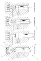
Figure 5 is a graphical illustration of the cyclic motion with respect to a camshaft angle of a plunger of the pump element ofFigure 3 operating off a three-lobe cam; -
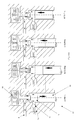
Figures 6a to 6d are sectional views of the pump element ofFigure 3 , operating with the inlet metering valve deactivated; -
Figure 7a to 7d are sectional views of the pump element ofFigure 3 , operating with the inlet metering valve activated; -
Figure 8 is an illustration of the pumping element ofFigure 1 starting the pressurising phase of the pumping stroke at a camshaft angle of 155 degrees; and, -
Figure 9 is an illustration of the pumping element ofFigure 7 starting the pressurising phase of the pumping stroke at a camshaft angle of 130 degrees. - Typically, a known high-pressure fuel pump of a common rail fuel system of a compression ignition internal combustion engine (referred to as the engine) has multiple pump elements operating in a phased cyclical manner. Each pump element is identical and, as shown in
Figure 1 , comprises a plunger, which is used to pressurise fuel within the pump element for delivery to a fuel rail common to each of the other pump elements. The plungers are driven by means of a cam mounted on an engine driven shaft. - The
pump element 2 includes apump chamber 6 and aninlet passage 4 to thepump chamber 6. Theinlet passage 4 is in communication with a low-pressure transfer pump (not shown) usually via a single inlet metering valve (not shown). The transfer pump serves to supply fuel from a low pressure fuel reservoir (not shown) to theinlet passage 4. Theinlet passage 4 is isolated from thepump chamber 6 by means of a hydraulically operated non-return inlet valve 8 (referred to as the inlet valve). Theinlet valve 8 is biased into a closed position by means of afirst spring 9 and fuel pressure within thepump chamber 6. Aplunger 10 is housed within thepump chamber 6 and is driven, in a reciprocating motion, by a camshaft (not shown). Theplunger 10 is in a bottom-dead-centre position when at a lowermost position (i.e. when the volume/capacity of thepump chamber 6 is a maximum) and in a top-dead-centre position when at an uppermost position (i.e. when the volume/capacity of thepump chamber 6 is a minimum). A pump cycle is said to have occurred when theplunger 10 has moved from the top-dead-centre position to the bottom-dead-centre position, and back to the top-dead-centre position. Theinlet valve 8 responds automatically to the motion of the plunger 10: as theplunger 10 moves from the bottom-dead-centre position to the top-dead-centre position, the increasing pressure in thepump chamber 6, in combination with the biasing force of thefirst spring 9, forces theinlet valve 8 into the closed position. As theplunger 10 returns to the bottom-dead-centre position, the decreasing pressure in thepump chamber 6, in combination with the pressure of the fuel in theinlet passage 4, urges theinlet valve 8 into an open position, against the force of thefirst spring 9. - An
outlet passage 12 from thepump chamber 6 is isolated from thepump chamber 6 by means of a hydraulically operated non-return outlet valve 14 (referred to as the outlet valve). Theoutlet passage 12 is in direct communication with a common fuel rail (not shown), so that pressure in both is substantially equal. The common rail receives pressurised fuel from theoutlet passage 12 from eachpump element 2 of the pump. Theoutlet valve 14 is biased into a closed position by high pressure fuel in the common rail, acting in combination with asecond spring 16. It will be appreciated that, in practice, the biasing forces provided by the first andsecond springs - In use, when the motion of the
plunger 10 serves to decrease the pressure in the pump chamber 6 (i.e. when theplunger 10 moves from the top-dead-centre position to the bottom-dead-centre position), theinlet valve 8 is caused to open, thereby permitting fuel delivery from theinlet passage 4 to thepump chamber 6. This part of the pump cycle is referred to as a filling stroke. Theoutlet valve 14 is biased into the closed position throughout the filling stroke due to the high pressure fuel in the common rail and the force from thesecond spring 16. Fuel delivery to thepump chamber 6 terminates at the end of the filling stroke, when theplunger 10 reaches the bottom-dead-centre position. - From the bottom-dead-centre position, the
plunger 10 moves to the top-dead-centre position. This part of the pump cycle is referred to as a pumping stroke, during which the motion of theplunger 10 serves to increase the fuel pressure in thepump chamber 6. During a pumping stroke, the fuel pressure in thepump chamber 6 can increase to several thousand atmospheres. When the fuel pressure in thepump chamber 6 exceeds an amount sufficient to overcome the fuel pressure in the outlet passage 12 (acting in combination with the second spring 16), theoutlet valve 14 is caused to open to permit high pressure fuel delivery from thepump chamber 6 through theoutlet passage 12 and, hence, to the common rail. The provision of theoutlet valve 14 ensures that the high-pressure fuel remains trapped in the common rail and cannot return to thepump chamber 6. A point will be reached nearing a latter stage of the pumping stroke when theoutlet valve 14 is caused to close under the high fuel pressure in the common rail, thus terminating the supply of fuel through theoutlet passage 12. - Throughout its operation, the
pump element 2 receives and displaces a maximum amount of fuel, which corresponds to the maximum volume/capacity of thepump chamber 6. It has been recognised that maximum fuel displacement from the high-pressure fuel pump is necessary when, for example, the engine is operating under a high load or during transient engine conditions where it is necessary to rapidly increase the fuel pressure in the common rail. When the engine conditions are such that maximum fuel delivery is not required, for example during a steady state engine condition, the inlet metering valve regulates the amount of fuel delivered by the transfer pump to theinlet passage 4 of thepumping element 2. The provision of the inlet metering valve means that the pumping duty of the high-pressure fuel pump is distributed substantially equally between the multiple pump elements. Therefore, regardless of the pumping requirements, eachpump element 2 completes a pumping cycle, or more particularly, a pumping stroke of a pumping cycle. The more pumping strokes apump element 2 completes, the greater the possibility that it will be subject to fatigue failure due to frequent exposure to high fuel pressure in thepump chamber 6. - It will be appreciated that the degree of fatigue a
pump element 2 is subject to is dependent on the frequency with which it is subject to a pressurising phase and not the duration of the pressurising phase. - The present invention improves on the above-described
pump element 2 by replacing theinlet valve 8 with a valve that does not respond automatically to the motion of theplunger 10. The construction of thepump element 17 in the present invention is substantially the same as described previously, in terms of the inlet andoutlet passages plunger 10 and theoutlet valve 14, but differs in a key respect. - Referring to
Figure 2 , in thepump element 17 of the present invention theinlet valve 8 of the knownpump element 2 is replaced by an inlet metering valve in the form of a solenoid latching valve 18 (referred to as the latching valve 18) which is controlled by an Engine Control Unit (ECU). The provision of the latchingvalve 18 means that the fuel displaced by thepump element 17 can be metered independently of the motion of theplunger 10, i.e. the latchingvalve 18 does not respond automatically to the motion of theplunger 10. - The latching
valve 18 includes anarmature 20 coupled to avalve head 22 via avalve stem 24. Thevalve head 22 is engageable with aseating surface 26 defined at aninlet port 28 to thepump chamber 6, which communicates with theinlet passage 4. Activation of the latchingvalve 18 causes thevalve head 22 of the latchingvalve 18 to move into engagement with theseating surface 26, thereby isolating thepump chamber 6 from theinlet passage 4. Deactivation of the latchingvalve 18 causes thevalve head 22 of the latchingvalve 18 to move away from theseating surface 26, thus providing communication between theinlet passage 4 and thepump chamber 6. -
Figure 2 shows thepump element 17 during the filling stroke of the plunger 10: when the latchingvalve 18 is deactivated, fuel is supplied, by means of the transfer pump, to thepump chamber 6 through theinlet passage 4. In one mode of operation, prior to beginning the pumping stroke, the latchingvalve 18 is activated to move thevalve head 22 into contact with theseating surface 26, thereby trapping the fuel in thepump chamber 6 and preventing further filling through theinlet passage 4. As the pressure of fuel in thepump chamber 6 is lower than the pressure of the fuel in the common rail, theoutlet valve 14 remains closed (as shown inFigure 3 ). The fuel pressure in thepump chamber 6 is increased during the subsequent pumping stroke of theplunger 10 as it moves from the bottom-dead-centre position to the top-dead-centre position. When the fuel pressure in thepump chamber 6 exceeds an amount sufficient to overcome the fuel pressure in theoutlet passage 12, theoutlet valve 14 is caused to open. Pressurised fuel within thepump chamber 6 is therefore able to flow through theoutlet passage 12 into the common rail. Once it has been activated, the latchingvalve 18 remains closed throughout the remainder of the pumping stroke. - Similar to the known
pump element 2, when thepump element 17 of the present invention is operated in this manner, the pump cycle displaces a maximum amount of fuel, which corresponds to the maximum volume/capacity of thepump chamber 6. It will be appreciated that the maximum pump capacity of the pump is therefore achieved when all pump elements are operated in the aforementioned manner (i.e. maximum capacity). - In other embodiments, however, the latching
valve 18 can be used to meter the amount of fuel displaced by theplunger 10 during the pumping stroke to precisely meet the demands of the engine at any given time. - Referring to
Figures 4a to 4d , fuel is supplied to thepump chamber 6 during the filling stroke of the plunger as previously described. During the initial stages of the pumping stroke, as theplunger 10 moves away from the bottom-dead-centre position, thevalve head 22 of the latchingvalue 18 is held away from theseating surface 26, thus allowing fuel to return from thepump chamber 6 through theinlet passage 4 into a transfer gallery (not shown). The transfer gallery is in communication with the low pressure fuel reservoir. This part of the pumping stroke is referred to as the "pre-pumping phase". The duration of the pre-pumping phase is determined by the ECU and is dependent on the engine load: the ECU increases and decreases the duration of the pre-pumping phase under lower and higher pumping requirements respectively. The pre-pumping phase is terminated when the latchingvalve 18 is activated, causing thevalve head 22 of the latchingvalve 18 to contact theseating surface 26 of thepump chamber 6. When the latchingvalve 18 is activated, fuel that remains trapped in thepump chamber 6 is pressurised under the motion of theplunger 10 moving to the top-dead-centre position. This phase of the pumping stroke is referred to as the "metering phase" or "pressurising phase". Once it has been activated, the latchingvalve 18 remains closed throughout the remainder of the pumping stroke. When the fuel pressure in thepump chamber 6 exceeds an amount sufficient to overcome the fuel pressure in theoutlet passage 12, theoutlet valve 14 is caused to open to permit high pressure fuel delivery from thepump chamber 6 through theoutlet passage 12 and, hence, to the common rail. - When the
pump element 17 is operated in this manner, the capacity of thepump chamber 6, and hence the amount of fuel displaced by theplunger 10, can be selected according to the pumping requirements. Thus, the overall pumping duty of the high-pressure pump can be, evenly or unevenly, distributed over the pump elements collectively. - In a second, alternative mode of operation, the latching
valve 18 can be controlled so as to decrease the leakage of fuel during the pumping stroke of the pump cycle. Knownpump elements 2 are subject to high pressure fuel leakages during the pumping stroke due to clearances between, for example, theplunger 10 and thepump chamber 6, which reduce the pump efficiency of thepump element 2. In order to increase the pump efficiency and thereby reduce energy losses, it is desirable to minimise the duration of the pumping stroke by maximising the average speed of theplunger 10 during the pumping stroke. The shape of the cam driving theplunger 10 results in phases of the pumping stroke during which the plunger is subject to periods of substantial acceleration and deceleration. During the pumping stroke, theplunger 10 accelerates from a zero velocity at the bottom-dead-centre position to a maximum velocity in a middle phase of the pumping stroke, and decelerates from the maximum velocity to a zero velocity at the top-dead-centre position. It will be appreciated that a significant proportion of the plunger's 10 acceleration and deceleration occurs in the initial and latter stages of the pumping stroke, respectively. Accordingly, the average speed of theplunger 10 in the initial and latter stages of the pumping stroke is relatively low compared to the maximum speed of theplunger 10. - By way of comparison, with reference to
Figure 5 , the full pumping stroke of the knownpump element 2 occurs over, for example, a camshaft angle range of 120 degrees to 180 degrees i.e. theplunger 10 is at the bottom-dead-centre position at a camshaft angle of 120 degrees and is at the top-dead-centre position at a camshaft angle of 180 degrees. This camshaft angle range constitutes the pressurising phase of the pumping stroke of thepump element 2, and is inclusive of the initial and latter stages of the pumping stroke, during which the average speed of theplunger 10 is relatively low. - In the present invention, the latching
valve 18 is deactivated to allow the fuel to flow from thepump chamber 6 through theinlet passage 4 during the initial stage of the pumping stroke, and is only activated at a camshaft angle of, for example, 135 degrees. In this instance, the cam shaft angle of 135 degrees represents the start of the pressurising phase of the pumping stroke. Once the latchingvalve 18 is activated, the pressurised fuel in the pump chamber 6 (acting in combination with latching valve 18) ensures that thevalve head 22 remains latched in the closed position, in contact with theseating surface 26 of thepump chamber 6, through the remainder of the pumping stroke i.e. until a cam shaft angle of 180 degrees. Therefore, the pressurising phase excludes the initial stage of the pumping stroke during which the average speed of theplunger 10 is relatively low. Accordingly, the average speed of theplunger 10 during the pressurising phase is increased, when compared to the average speed of theplunger 10 of the knownpump element 2 during the corresponding pressuring phase i.e. from a cam shaft angle of 120 degrees to 180 degrees. Therefore, the duration over which thepump element 17 of the present invention is subject to high-pressure fuel leakages is reduced and pump efficiency is increased. - In a third alternative mode of operation, the overall pumping duty of the high-pressure fuel pump can be unevenly distributed over multiple pump elements by removing the pumping duty of one or more pump elements, subject to pumping requirements. Referring to
Figures 6a to 6d , the pumping duty of any one of the multiple pump elements can be removed by keeping the latchingvalve 18 of thatpump element 17 deactivated throughout the pump cycle. As previously described, fuel is supplied to thepump chamber 6 from theinlet passage 4 during the filling stroke. With the latchingvalve 18 still deactivated, continued movement of theplunger 10 through the pumping stroke causes the fuel in thepump chamber 6 to be displaced back through theinlet passage 4 into the transfer gallery. Accordingly, the fuel in thepump chamber 6 is prevented from being pressurised to a level sufficient to overcome the fuel pressure in theoutlet passage 12 and theoutlet valve 14 remains closed. The pumping duty of thispump element 17 is therefore effectively disabled. In this operation, the pumping stroke is effectively a "spill" stroke where fuel is spilled back to the low-pressure fuel reservoir. - In a fourth alternative mode of operation, the pumping duty of the
pump element 17 can be removed by keeping the latchingvalve 18 activated throughout the entire pump cycle. Referring toFigures 7a to 7d , with the latchingvalve 18 activated, thevalve head 22 of the latchingvalve 18 remains seated on theseating surface 26 of thepump chamber 6 and, in so doing, prevents the supply of fuel from theinlet passage 4 to thepump chamber 6. In this operation, the continued movement of theplunger 10 through the pump cycle serves only to draw a cavity in thepump chamber 6 during the filling stroke, and compress the cavity in the pumping stroke. Accordingly, the pumping duty of thepump element 17 is disabled. - The third and the fourth modes of operation have the advantage of removing the pressurising phase of the pumping stroke of the
pump element 17, thereby reducing the total number of pressurising phases that thepump element 17 is subjected to. Therefore, the possibility of fatigue failure is reduced. - Despite the pumping duty of the
pump element 17 being disabled in both the third and the fourth modes of operation, the fourth mode of operation offers a further benefit as the fuel is prevented from entering thepump chamber 6 and so thepump element 17 is not subject to any low-pressure pumping losses, for example athigh plunger 10 speeds where energy is wasted as fuel in thepump chamber 6 is displaced back through theinlet passage 4 due to the pressure rise in overcoming flow restrictions across thevalve 18. - In another embodiment (not shown), the latching valve may be replaced with a valve which can be opened against pressurised fuel in the
pump chamber 6 so that it is possible to exclude both the initial and latter stages of the pumping stroke in order to further increase the average speed of theplunger 10 during the pressurising phase. In another mode of operation it would be possible to exclude the latter stage of the pumping stroke only from the pressurising phase, while the valve remains closed for the initial stage of the pumping stroke. - It will be appreciated that the ECU controls independently the valves of each of the pump elements to meter the fuel flow into each
pump chamber 6, whilst ensuring that the pump elements collectively displace a sufficient amount of fuel according to the pumping requirements. - Removing, increasing or decreasing the pressurising phase of the pumping stroke of the pump elements means that the overall pumping duty of the high-pressure fuel pump can be evenly or unevenly distributed across the pump elements collectively.
- By way of comparison, with reference to
Figure 8 , a high-pressure fuel pump comprising three pump elements, each the same as the knownpumping element 2, will have three pumping strokes. The overall pumping duty of the high-pressure fuel pump is substantially evenly distributed over the three pump elements. Therefore, if the high-pressure fuel pump is required to deliver, for example, 660 mm3 of pressurised fuel to the common rail, eachpump element 2 must displace 220 mm3 of fuel. Accordingly, eachpump element 2 will be subject to a pressurising phase over the last 25 degrees of its pumping stroke. - Alternatively, with reference to
Figure 9 , if a high-pressure fuel pump comprising threepump elements 17 is required to displace 660 mm3 of pressurised fuel to the common rail, the second and third pump elements could be disabled and thefirst pump element 17 only could pressurise the fuel within thepump chamber 6 starting from a cam shaft angle of approximately 130 degrees. In such circumstances, only thefirst pump element 17 is subject to a pressurising phase of the pumping stroke. The overall pumping duty of the high-pressure fuel pump could then subsequently be re-distributed over only the second pump element, for example, leaving the first and third pump elements disabled. Accordingly, during a steady state engine operation, for example, the overall pump duty could be re-distributed over individual pump elements sequentially, thereby reducing the frequency with which the pump elements are subject to a pressurising phase and, hence, reducing the possibility of fatigue failure. Whereas in a known high-pressure fuel pump having threepump elements 2 such as those inFigure 1 would use all three pump elements, each pumping over 25 degrees of the pump cycle (i.e. a total of 75 degrees per pump cycle during which the pump elements are exposed to a pressurising phase), in this example of the present invention only one of thepump elements 17 pumps for just 50 degrees per pump cycle. - Re-distributing the overall pumping duty of the high-pressure fuel pump between pump elements avoids some of the pump elements becoming hotter than other pump elements, which is desirable to increase the durability of the pump elements.
Claims (15)
- A control method for a high-pressure fuel pump comprising a plurality of pump elements (17), each of which comprises a plunger (10) having a pumping stroke during which fuel within a pump chamber (6) is pressurised and a filling stroke during which fuel is supplied to the pump chamber (6) for pressurisation, and a valve (18) for controlling fuel flow into and/or out of the pump chamber (6), the high-pressure fuel pump having a maximum pump capacity corresponding to all of the pump elements pumping at maximum capacity, the method comprising reducing the pump capacity of the high-pressure fuel pump by reducing the pump duty of at least one of the pump elements to less than its maximum capacity.
- The control method of Claim 1, wherein the pump capacity of the high-pressure fuel pump is unevenly distributed across the pump elements (17).
- The control method of Claim 2, wherein the valve (18) for controlling fuel flow into and/or out of the pump chamber (6) is a latching valve (18).
- The control method of Claim 2 or 3, comprising, for at least one of the pump elements (17),
holding the valve (18) in an open position during a filling stroke of the plunger (10) to permit fuel to be supplied to the pump chamber (6); and
holding the valve (18) in the open position for the one or more periods of a pumping stroke of the plunger (10) so as to dispel a proportion of fuel that is supplied to the pump chamber (6) during the filling stroke back through the valve (18),
wherein the one or more periods of the pumping stroke of one of the pump elements (17) is different from that of the other elements (17). - The control method of any one of Claims 1 to 3, including holding the valve (18) of at least one of the pump elements in the open position throughout both the filling stroke and the pumping stroke so as to disable said pump element (17).
- The control method of any one of Claims 1 to 3, including, for at least one of the pump elements (17), holding the valve (18) in a closed position throughout both the filling stroke and the pumping stroke so as to disable said pump element (17).
- A high-pressure fuel pump comprising a plurality of pump elements (17), each of which comprises a plunger (10) having a pumping stroke during which fuel within a pump chamber (6) is pressurised and a filling stroke during which fuel is supplied to the pump chamber (6) for pressurisation, and a valve (18) for controlling fuel flow into and/or out of the pump chamber (6), the high-pressure fuel pump having a maximum pump capacity corresponding to all of the pump elements pumping at maximum capacity, the high-pressure fuel pump comprising means for reducing the pump capacity of the high-pressure fuel pump by reducing the pump duty of at least one of the pump elements to less than its maximum capacity.
- The high-pressure fuel pump as claimed in Claim 7, wherein the valve (18) for controlling fuel flow into and/or out of the pump chamber (6) is a latching valve (18).
- The high-pressure fuel pump as claimed in Claim 7 or 8, comprising a common pump housing block, wherein the plurality of pump elements (17) are housed within the common housing block.
- The high-pressure fuel pump as claimed in any one of Claims 7 to 9, wherein the pump capacity of the high-pressure fuel pump is unevenly distributed across the pump elements (17).
- The high-pressure fuel pump as claimed in Claim 10, comprising, for at least one of the pump elements (17),
means for holding the valve (18) in an open position during a filling stroke of the plunger (10) to permit fuel to be supplied to the pump chamber (6); and
means for holding the valve (18) in the open position for one or more periods of a pumping stroke of the plunger (10) so as to dispel a proportion of fuel that is supplied to the pump chamber (6) during the filling stroke back through the valve (18);
wherein the one or more periods of the pumping stroke of one of the pump elements (17) is different from that of the other elements (17). - The high-pressure fuel pump as claimed in any one of Claims 7 to 10, including holding the valve (18) of at least one of the pump elements in the open position throughout both the filling stroke and the pumping stroke so as to disable said pump element (17).
- The high-pressure fuel pump as claimed in any one of Claims 7 to 10, including, for at least one of the pump elements (17), holding the valve (18) in a closed position throughout both the filling stroke and the pumping stroke so as to disable said pump element (17).
- A control method for a high-pressure fuel pump comprising a plurality of pump elements (17), each of which comprises a plunger (10) for pressurising fuel within a pump chamber (6) and a valve (18) for controlling fuel delivery into and/or out of the pump chamber (6), the method comprising;
holding the valve (18) in an open position during a filling stroke of the plunger (10) to permit fuel to be supplied to the pump chamber (6);
maintaining the valve (18) in the open position for at least one selected stage of a pumping stroke of the plunger so as to dispel a proportion of fuel that is supplied to the pump chamber (6) during the filling stroke back through the valve (18); and,
closing the valve (18) during the pumping stroke, other than during the at least one selected stage, so as to permit pressurisation of the fuel within the pump chamber (6),
wherein the at least one selected stage includes that period of the pumping stroke for which the plunger (10) either accelerates from and/or decelerates to zero velocity. - The control method of Claim 14, wherein the at least one selected stage includes the initial and/or latter stages of the pumping stroke.
Priority Applications (2)
| Application Number | Priority Date | Filing Date | Title |
|---|---|---|---|
| EP09157959A EP2241744A1 (en) | 2009-04-15 | 2009-04-15 | Common Rail Fuel Pump and Control Method for a Common Rail Fuel Pump |
| PCT/EP2010/054933 WO2010119086A1 (en) | 2009-04-15 | 2010-04-15 | Common rail fuel pump and control method for a common rail fuel pump |
Applications Claiming Priority (1)
| Application Number | Priority Date | Filing Date | Title |
|---|---|---|---|
| EP09157959A EP2241744A1 (en) | 2009-04-15 | 2009-04-15 | Common Rail Fuel Pump and Control Method for a Common Rail Fuel Pump |
Publications (1)
| Publication Number | Publication Date |
|---|---|
| EP2241744A1 true EP2241744A1 (en) | 2010-10-20 |
Family
ID=41066210
Family Applications (1)
| Application Number | Title | Priority Date | Filing Date |
|---|---|---|---|
| EP09157959A Withdrawn EP2241744A1 (en) | 2009-04-15 | 2009-04-15 | Common Rail Fuel Pump and Control Method for a Common Rail Fuel Pump |
Country Status (2)
| Country | Link |
|---|---|
| EP (1) | EP2241744A1 (en) |
| WO (1) | WO2010119086A1 (en) |
Cited By (4)
| Publication number | Priority date | Publication date | Assignee | Title |
|---|---|---|---|---|
| WO2013053794A1 (en) * | 2011-10-14 | 2013-04-18 | Continental Automotive Gmbh | Pump arrangement |
| WO2013076095A1 (en) * | 2011-11-24 | 2013-05-30 | Continental Automotive Gmbh | Method for operating an injection system |
| WO2015007446A1 (en) * | 2013-07-18 | 2015-01-22 | Continental Automotive Gmbh | Method for operating a fuel injection system of an internal combustion engine |
| CN104389709A (en) * | 2014-08-20 | 2015-03-04 | 南岳电控(衡阳)工业技术有限公司 | High-pressure fuel feed pump for high-pressure common rail fuel injection system |
Families Citing this family (3)
| Publication number | Priority date | Publication date | Assignee | Title |
|---|---|---|---|---|
| EP2706222B1 (en) | 2012-09-06 | 2016-07-13 | Delphi International Operations Luxembourg S.à r.l. | Pump unit |
| DE102014225982A1 (en) * | 2014-12-16 | 2016-06-16 | Robert Bosch Gmbh | Pump, in particular high-pressure fuel pump |
| CN105952561B (en) * | 2016-06-18 | 2023-11-14 | 常州博瑞油泵油嘴有限公司 | Common rail pump component of high-pressure common rail pump of single-cylinder diesel engine |
Citations (5)
| Publication number | Priority date | Publication date | Assignee | Title |
|---|---|---|---|---|
| US5697343A (en) * | 1996-07-08 | 1997-12-16 | Mitsubishi Denki Kabushiki Kaisha | Fuel injector system |
| FR2805861A1 (en) * | 2000-03-01 | 2001-09-07 | Mitsubishi Electric Corp | Fuel feed for motor vehicle internal combustion engine has fuel pump passing inlet valve through reciprocating movement of piston to discharge valve across outlet valve |
| EP1281860A2 (en) * | 2001-08-02 | 2003-02-05 | Siemens Aktiengesellschaft | Injection System for an Internal Combustion Engine and Method for Operating the Same |
| EP1306553A2 (en) * | 2001-10-27 | 2003-05-02 | Robert Bosch Gmbh | Fuel pump, fuel system and method for operating a fuel system and an internal combustion engine |
| DE102004023962A1 (en) * | 2004-05-14 | 2005-12-01 | Robert Bosch Gmbh | Fuel high pressure pump and injection system controlling method, involves reducing number of discharge strokes of fuel high-pressure pump relative to number of injections, if injection quantity is smaller than minimum output |
Family Cites Families (2)
| Publication number | Priority date | Publication date | Assignee | Title |
|---|---|---|---|---|
| US4884549A (en) * | 1986-04-21 | 1989-12-05 | Stanadyne Automotive Corp. | Method and apparatus for regulating fuel injection timing and quantity |
| DE102005031253A1 (en) * | 2005-07-05 | 2007-01-18 | Dr.Ing.H.C. F. Porsche Ag | Method and device for controlling a fuel injection system for an internal combustion engine of a vehicle |
-
2009
- 2009-04-15 EP EP09157959A patent/EP2241744A1/en not_active Withdrawn
-
2010
- 2010-04-15 WO PCT/EP2010/054933 patent/WO2010119086A1/en active Application Filing
Patent Citations (6)
| Publication number | Priority date | Publication date | Assignee | Title |
|---|---|---|---|---|
| US5697343A (en) * | 1996-07-08 | 1997-12-16 | Mitsubishi Denki Kabushiki Kaisha | Fuel injector system |
| FR2805861A1 (en) * | 2000-03-01 | 2001-09-07 | Mitsubishi Electric Corp | Fuel feed for motor vehicle internal combustion engine has fuel pump passing inlet valve through reciprocating movement of piston to discharge valve across outlet valve |
| US6343588B1 (en) * | 2000-03-01 | 2002-02-05 | Mitsubishi Denki Kabushiki Kaisha | Variable delivery fuel supply device |
| EP1281860A2 (en) * | 2001-08-02 | 2003-02-05 | Siemens Aktiengesellschaft | Injection System for an Internal Combustion Engine and Method for Operating the Same |
| EP1306553A2 (en) * | 2001-10-27 | 2003-05-02 | Robert Bosch Gmbh | Fuel pump, fuel system and method for operating a fuel system and an internal combustion engine |
| DE102004023962A1 (en) * | 2004-05-14 | 2005-12-01 | Robert Bosch Gmbh | Fuel high pressure pump and injection system controlling method, involves reducing number of discharge strokes of fuel high-pressure pump relative to number of injections, if injection quantity is smaller than minimum output |
Cited By (10)
| Publication number | Priority date | Publication date | Assignee | Title |
|---|---|---|---|---|
| WO2013053794A1 (en) * | 2011-10-14 | 2013-04-18 | Continental Automotive Gmbh | Pump arrangement |
| WO2013076095A1 (en) * | 2011-11-24 | 2013-05-30 | Continental Automotive Gmbh | Method for operating an injection system |
| CN103958883A (en) * | 2011-11-24 | 2014-07-30 | 欧陆汽车有限责任公司 | Method for operating an injection system |
| US9086029B2 (en) | 2011-11-24 | 2015-07-21 | Continental Automotive Gmbh | Method for operating an injection system |
| CN103958883B (en) * | 2011-11-24 | 2017-03-08 | 欧陆汽车有限责任公司 | Method for making spraying system work |
| WO2015007446A1 (en) * | 2013-07-18 | 2015-01-22 | Continental Automotive Gmbh | Method for operating a fuel injection system of an internal combustion engine |
| CN105593500A (en) * | 2013-07-18 | 2016-05-18 | 大陆汽车有限公司 | Method for operating a fuel injection system of an internal combustion engine |
| US9739209B2 (en) | 2013-07-18 | 2017-08-22 | Continental Automotive Gmbh | Method for operating a fuel injection system of an internal combustion engine |
| CN104389709A (en) * | 2014-08-20 | 2015-03-04 | 南岳电控(衡阳)工业技术有限公司 | High-pressure fuel feed pump for high-pressure common rail fuel injection system |
| CN104389709B (en) * | 2014-08-20 | 2017-02-01 | 南岳电控(衡阳)工业技术股份有限公司 | High-pressure fuel feed pump for high-pressure common rail fuel injection system |
Also Published As
| Publication number | Publication date |
|---|---|
| WO2010119086A1 (en) | 2010-10-21 |
Similar Documents
| Publication | Publication Date | Title |
|---|---|---|
| JP4165572B2 (en) | Fuel supply device for internal combustion engine | |
| US7179060B2 (en) | Variable discharge pump with two pumping plungers and shared shuttle member | |
| JP4353288B2 (en) | Fuel pump | |
| EP2241744A1 (en) | Common Rail Fuel Pump and Control Method for a Common Rail Fuel Pump | |
| US8136508B2 (en) | Selective displacement control of multi-plunger fuel pump | |
| US7574995B2 (en) | Fuel injection system | |
| JP2009133306A (en) | Fuel injection system | |
| CN1699736A (en) | Method and system of holding fuel directly spray into internal-combustion engine | |
| JP2006207451A (en) | Fuel pump and delivery valve equipped in fuel pump | |
| EP2044321B1 (en) | Fuel injection system | |
| US7350505B2 (en) | Common rail fuel pump | |
| US6901911B2 (en) | Pump and hydraulic system with low pressure priming and over pressurization avoidance features | |
| US7517200B2 (en) | Variable discharge fuel pump | |
| KR101514464B1 (en) | Fuel injection system having high-pressure pumps with magnetically operative suction valve | |
| CN114382599A (en) | Fuel system management during cylinder deactivation operation | |
| CN112805469B (en) | Water injection pump | |
| JP2004156574A (en) | Fluid loss/oil pressure fluctuation reducing structure for common rail (cr) fuel injection system | |
| EP0962650A2 (en) | Accumulator-type fuel injection apparatus and control method for the same | |
| EP1361360A1 (en) | High pressure fuel pump | |
| EP0992675A2 (en) | Fuel system | |
| CN107939574B (en) | Common rail fuel system with pump-accumulator injector | |
| EP2568156B1 (en) | Fuel injection system for an internal combustion engine, method for injecting fuel, as well as an internal combustion engine | |
| CN110685825B (en) | Method for operating a fuel delivery device for cryogenic fuels and fuel delivery device | |
| EP2495429A1 (en) | Fuel pump for delivering fuel to a fuel injector and system comprising a multitude of such fuel pumps | |
| CN113994090A (en) | Pump, in particular high-pressure fuel pump |
Legal Events
| Date | Code | Title | Description |
|---|---|---|---|
| PUAI | Public reference made under article 153(3) epc to a published international application that has entered the european phase |
Free format text: ORIGINAL CODE: 0009012 |
|
| AK | Designated contracting states |
Kind code of ref document: A1 Designated state(s): AT BE BG CH CY CZ DE DK EE ES FI FR GB GR HR HU IE IS IT LI LT LU LV MC MK MT NL NO PL PT RO SE SI SK TR |
|
| AX | Request for extension of the european patent |
Extension state: AL BA RS |
|
| STAA | Information on the status of an ep patent application or granted ep patent |
Free format text: STATUS: THE APPLICATION IS DEEMED TO BE WITHDRAWN |
|
| 18D | Application deemed to be withdrawn |
Effective date: 20110421 |