JP4353288B2 - Fuel pump - Google Patents
Fuel pump Download PDFInfo
- Publication number
- JP4353288B2 JP4353288B2 JP2007206185A JP2007206185A JP4353288B2 JP 4353288 B2 JP4353288 B2 JP 4353288B2 JP 2007206185 A JP2007206185 A JP 2007206185A JP 2007206185 A JP2007206185 A JP 2007206185A JP 4353288 B2 JP4353288 B2 JP 4353288B2
- Authority
- JP
- Japan
- Prior art keywords
- fuel
- valve
- opening
- pressurizing chamber
- pressure
- Prior art date
- Legal status (The legal status is an assumption and is not a legal conclusion. Google has not performed a legal analysis and makes no representation as to the accuracy of the status listed.)
- Expired - Fee Related
Links
Images


Classifications
-
- F—MECHANICAL ENGINEERING; LIGHTING; HEATING; WEAPONS; BLASTING
- F02—COMBUSTION ENGINES; HOT-GAS OR COMBUSTION-PRODUCT ENGINE PLANTS
- F02M—SUPPLYING COMBUSTION ENGINES IN GENERAL WITH COMBUSTIBLE MIXTURES OR CONSTITUENTS THEREOF
- F02M59/00—Pumps specially adapted for fuel-injection and not provided for in groups F02M39/00 -F02M57/00, e.g. rotary cylinder-block type of pumps
- F02M59/20—Varying fuel delivery in quantity or timing
- F02M59/34—Varying fuel delivery in quantity or timing by throttling of passages to pumping elements or of overflow passages, e.g. throttling by means of a pressure-controlled sliding valve having liquid stop or abutment
-
- F—MECHANICAL ENGINEERING; LIGHTING; HEATING; WEAPONS; BLASTING
- F02—COMBUSTION ENGINES; HOT-GAS OR COMBUSTION-PRODUCT ENGINE PLANTS
- F02M—SUPPLYING COMBUSTION ENGINES IN GENERAL WITH COMBUSTIBLE MIXTURES OR CONSTITUENTS THEREOF
- F02M59/00—Pumps specially adapted for fuel-injection and not provided for in groups F02M39/00 -F02M57/00, e.g. rotary cylinder-block type of pumps
- F02M59/20—Varying fuel delivery in quantity or timing
- F02M59/36—Varying fuel delivery in quantity or timing by variably-timed valves controlling fuel passages to pumping elements or overflow passages
- F02M59/366—Valves being actuated electrically
-
- F—MECHANICAL ENGINEERING; LIGHTING; HEATING; WEAPONS; BLASTING
- F02—COMBUSTION ENGINES; HOT-GAS OR COMBUSTION-PRODUCT ENGINE PLANTS
- F02M—SUPPLYING COMBUSTION ENGINES IN GENERAL WITH COMBUSTIBLE MIXTURES OR CONSTITUENTS THEREOF
- F02M59/00—Pumps specially adapted for fuel-injection and not provided for in groups F02M39/00 -F02M57/00, e.g. rotary cylinder-block type of pumps
- F02M59/44—Details, components parts, or accessories not provided for in, or of interest apart from, the apparatus of groups F02M59/02 - F02M59/42; Pumps having transducers, e.g. to measure displacement of pump rack or piston
- F02M59/46—Valves
- F02M59/462—Delivery valves
-
- F—MECHANICAL ENGINEERING; LIGHTING; HEATING; WEAPONS; BLASTING
- F04—POSITIVE - DISPLACEMENT MACHINES FOR LIQUIDS; PUMPS FOR LIQUIDS OR ELASTIC FLUIDS
- F04B—POSITIVE-DISPLACEMENT MACHINES FOR LIQUIDS; PUMPS
- F04B1/00—Multi-cylinder machines or pumps characterised by number or arrangement of cylinders
- F04B1/04—Multi-cylinder machines or pumps characterised by number or arrangement of cylinders having cylinders in star- or fan-arrangement
- F04B1/0404—Details or component parts
- F04B1/0448—Sealing means, e.g. for shafts or housings
-
- F—MECHANICAL ENGINEERING; LIGHTING; HEATING; WEAPONS; BLASTING
- F04—POSITIVE - DISPLACEMENT MACHINES FOR LIQUIDS; PUMPS FOR LIQUIDS OR ELASTIC FLUIDS
- F04B—POSITIVE-DISPLACEMENT MACHINES FOR LIQUIDS; PUMPS
- F04B1/00—Multi-cylinder machines or pumps characterised by number or arrangement of cylinders
- F04B1/04—Multi-cylinder machines or pumps characterised by number or arrangement of cylinders having cylinders in star- or fan-arrangement
- F04B1/0404—Details or component parts
- F04B1/0452—Distribution members, e.g. valves
- F04B1/0456—Cylindrical
-
- F—MECHANICAL ENGINEERING; LIGHTING; HEATING; WEAPONS; BLASTING
- F04—POSITIVE - DISPLACEMENT MACHINES FOR LIQUIDS; PUMPS FOR LIQUIDS OR ELASTIC FLUIDS
- F04B—POSITIVE-DISPLACEMENT MACHINES FOR LIQUIDS; PUMPS
- F04B53/00—Component parts, details or accessories not provided for in, or of interest apart from, groups F04B1/00 - F04B23/00 or F04B39/00 - F04B47/00
- F04B53/10—Valves; Arrangement of valves
- F04B53/1085—Valves; Arrangement of valves having means for limiting the opening height
-
- Y—GENERAL TAGGING OF NEW TECHNOLOGICAL DEVELOPMENTS; GENERAL TAGGING OF CROSS-SECTIONAL TECHNOLOGIES SPANNING OVER SEVERAL SECTIONS OF THE IPC; TECHNICAL SUBJECTS COVERED BY FORMER USPC CROSS-REFERENCE ART COLLECTIONS [XRACs] AND DIGESTS
- Y10—TECHNICAL SUBJECTS COVERED BY FORMER USPC
- Y10T—TECHNICAL SUBJECTS COVERED BY FORMER US CLASSIFICATION
- Y10T137/00—Fluid handling
- Y10T137/7722—Line condition change responsive valves
- Y10T137/7738—Pop valves
Abstract
Description
本発明は、例えば筒内直噴型エンジン等の内燃機関に適用され、燃料噴射弁(インジェクタ)に向けて高圧燃料を供給するための燃料ポンプに係る。特に、本発明は、燃料ポンプの吐出効率を向上させるための対策に関する。 The present invention is applied to an internal combustion engine such as an in-cylinder direct injection engine, for example, and relates to a fuel pump for supplying high-pressure fuel toward a fuel injection valve (injector). In particular, the present invention relates to measures for improving the discharge efficiency of a fuel pump.
従来より、例えば筒内直噴型エンジンのようにインジェクタへ供給する燃料に高い圧力が要求されるエンジンにあっては、燃料タンクから送られてきた燃料を高圧燃料ポンプで加圧してインジェクタに向けて供給するようになっている。 2. Description of the Related Art Conventionally, in an engine where high pressure is required for fuel supplied to an injector, such as an in-cylinder direct injection engine, the fuel sent from the fuel tank is pressurized with a high-pressure fuel pump and directed to the injector. To supply.
具体的に、この種のエンジンにおける燃料供給システムの構成としては、下記の特許文献1にも開示されているように、燃料タンクから燃料を送り出すフィードポンプ、このフィードポンプによって送り出された燃料を加圧する高圧燃料ポンプを備えている。そして、この高圧燃料ポンプによって加圧された燃料を、複数のインジェクタが接続されたデリバリパイプに貯留するようになっている。これにより、インジェクタの開弁動作に伴って、デリバリパイプに貯留されている高圧燃料が、その開弁されたインジェクタから燃焼室に向けて噴射されることになる。
Specifically, as disclosed in
また、この種のエンジンの燃料供給系に備えられる上記高圧燃料ポンプは、シリンダ内で往復移動するプランジャと、そのプランジャ及びシリンダによって区画形成される加圧室と、この加圧室の吐出側に配設された吐出弁(チェック弁)とを備えている。そして、シリンダ内でのプランジャの往復移動により加圧室の容積が変化し、この容積の拡大時には加圧室に燃料が吸入される一方、この容積の縮小時の所定タイミングで吐出弁が開放してデリバリパイプに向けて高圧燃料が圧送されるようになっている。 The high-pressure fuel pump provided in the fuel supply system of this type of engine includes a plunger that reciprocates in a cylinder, a pressurization chamber that is defined by the plunger and the cylinder, and a discharge side of the pressurization chamber. And a discharge valve (check valve) arranged. The volume of the pressurizing chamber changes due to the reciprocating movement of the plunger in the cylinder, and when the volume is increased, fuel is sucked into the pressurizing chamber, while the discharge valve is opened at a predetermined timing when the volume is reduced. The high-pressure fuel is pumped toward the delivery pipe.
より具体的に、この高圧燃料ポンプには、加圧室とその吸入側の低圧燃料配管とを連通・遮断する電磁スピル弁が設けられており、加圧行程では、シリンダ内でのプランジャの移動により加圧室が縮小していく。そして、この加圧行程中において電磁スピル弁が開弁されている間は、加圧室から低圧燃料配管へ燃料が流出(フィードポンプ側へ流出)するため、デリバリパイプに向けての燃料圧送は行われない。これに対し、この加圧行程中に電磁スピル弁が閉弁されると、この加圧室内の圧力(燃料圧力)が上昇していき、この圧力が、吐出弁の弁体(以下、バルブ体という)を閉鎖方向に付勢しているコイルスプリングの付勢力とデリバリパイプ内の燃料圧力とを足し合わせた合力を上回ると吐出弁が開動作を開始し、電磁スピル弁の閉弁期間中にデリバリパイプに向けての燃料圧送が行われる。このように、加圧行程中における電磁スピル弁の閉弁期間を制御することによって、高圧燃料ポンプからデリバリパイプへの燃料圧送量が調整されるようになっている。 More specifically, the high-pressure fuel pump is provided with an electromagnetic spill valve that communicates and shuts off the pressurizing chamber and the low-pressure fuel pipe on the suction side. During the pressurization stroke, the plunger moves in the cylinder. As a result, the pressurizing chamber shrinks. While the electromagnetic spill valve is open during this pressurization stroke, fuel flows out from the pressurization chamber to the low-pressure fuel pipe (flows out to the feed pump side). Not done. On the other hand, when the electromagnetic spill valve is closed during the pressurization stroke, the pressure (fuel pressure) in the pressurization chamber increases, and this pressure is increased by the valve body of the discharge valve (hereinafter referred to as the valve body). When the combined force of the biasing force of the coil spring biasing in the closing direction and the fuel pressure in the delivery pipe is exceeded, the discharge valve starts to open and the electromagnetic spill valve is closed. Fuel is pumped toward the delivery pipe. In this way, by controlling the closing period of the electromagnetic spill valve during the pressurization stroke, the fuel pumping amount from the high-pressure fuel pump to the delivery pipe is adjusted.
ところで、この種の高圧燃料ポンプを備えた燃料供給系にあっては、エンジンが停止された際には、それまで上記高圧燃料ポンプによってデリバリパイプ内に向けて高圧燃料が圧送されていたために、このデリバリパイプ内圧が高圧状態となっている可能性が高い。そして、エンジン停止状態で、デリバリパイプ内圧が高圧状態のまま維持される状況では、このデリバリパイプ内圧が作用するインジェクタ内部空間の圧力とインジェクタの噴射口が臨む気筒の内圧との差が大きくなっていることなどが原因で、インジェクタの噴射口から気筒内に向けて燃料が漏れ出してしまう可能性がある。このような状況では、この気筒内に漏れ出した燃料の存在が、次回のエンジン始動に悪影響を及ぼしてしまうことが懸念される。 By the way, in the fuel supply system equipped with this type of high-pressure fuel pump, when the engine was stopped, the high-pressure fuel was pumped by the high-pressure fuel pump into the delivery pipe until then, This delivery pipe internal pressure is likely to be in a high pressure state. In a situation where the internal pressure of the delivery pipe is maintained in a high pressure state while the engine is stopped, the difference between the pressure in the injector internal space where the internal pressure of the delivery pipe acts and the internal pressure of the cylinder facing the injector injection port becomes large. For example, fuel may leak from the injector injection port into the cylinder. In such a situation, there is a concern that the presence of fuel leaking into the cylinder may adversely affect the next engine start.
この点に鑑み、例えば下記の特許文献2や特許文献3では、上記加圧室の吐出側に配設された上記チェック弁に微小孔を形成しておき、エンジン停止後には、この微小孔から高圧燃料ポンプ側に燃料を徐々に戻していくことによってデリバリパイプ内圧を低下させ、これにより、上記インジェクタからの燃料漏れを防止するようにしている。
しかしながら、上述した特許文献2や特許文献3の構成では以下に述べる課題があった。 However, the configurations of Patent Document 2 and Patent Document 3 described above have the following problems.
上述した如く特許文献2や特許文献3の構成では、エンジンの停止時にデリバリパイプ内圧を低下させることによりインジェクタからの燃料漏れを防止できるものの、その後のエンジン始動時にあっては、プランジャの下降動作に伴う吸入行程時に、上記チェック弁の微小孔から比較的大量の燃料が高速度で逆流する可能性がある。このような燃料の逆流が発生すると、燃料タンク側からの燃料導入量が少なくなり、燃料ポンプの吐出効率を低下させてしまうことに繋がる。 As described above, in the configurations of Patent Document 2 and Patent Document 3, fuel leakage from the injector can be prevented by reducing the internal pressure of the delivery pipe when the engine is stopped. However, when the engine is subsequently started, the plunger is lowered. During the accompanying intake stroke, a relatively large amount of fuel may flow backward at a high speed from the microhole of the check valve. If such a backflow of fuel occurs, the amount of fuel introduced from the fuel tank side decreases, leading to a decrease in the discharge efficiency of the fuel pump.
また、上記微小孔を経て高速度で逆流する燃料にキャビテーション・エロージョン(高速度で流れる燃料中に生じる気泡の破裂に伴う衝撃力)が発生し、高圧燃料ポンプに悪影響を及ぼしてしまう可能性もある。 In addition, cavitation erosion (impact force accompanying burst of bubbles generated in fuel flowing at high speed) may occur in the fuel that flows backward at high speed through the micropores, which may adversely affect the high-pressure fuel pump. is there.
本発明は、かかる点に鑑みてなされたものであり、その目的とするところは、停止時に吐出側の燃料圧力を低下させるための微小な隙間をチェック弁に備えた燃料ポンプに対し、吸入行程時に、この微小な隙間からの燃料逆流を防止し、吐出効率の向上を図ることができる構成を提供することにある。 The present invention has been made in view of the above points, and an object of the present invention is to provide an intake stroke to a fuel pump having a check valve with a minute gap for reducing the fuel pressure on the discharge side when stopped. In some cases, the present invention provides a configuration capable of preventing the fuel backflow from the minute gap and improving the discharge efficiency.
−課題の解決原理−
上記の目的を達成するために講じられた本発明の解決原理は、ポンプ停止時にポンプ吐出側の燃料圧力を低下させるために設けられる微小隙間を閉塞可能な構成とし、燃料ポンプの吸入行程ではこの微小隙間を閉塞することで、この微小隙間からの燃料の逆流を防止できるようにしている。特に、スピル弁を備えた燃料ポンプにおいては、このスピル弁の開閉動作と微小隙間を開閉するための機構部とを連結することで、スピル弁を開閉作動させるための駆動源を、微小隙間を開閉するための駆動源として利用可能な構成としている。
-Solving principle-
The solution principle of the present invention taken in order to achieve the above-described object is that the minute gap provided for reducing the fuel pressure on the pump discharge side can be closed when the pump is stopped. By closing the minute gap, the backflow of fuel from the minute gap can be prevented. In particular, in a fuel pump equipped with a spill valve, a drive source for opening and closing the spill valve is connected by connecting the opening and closing operation of the spill valve and a mechanism for opening and closing the minute gap. The structure can be used as a drive source for opening and closing.
−解決手段−
具体的に、本発明は、燃料を加圧するための加圧室と、この加圧室の吐出側に配設され且つ閉弁方向への付勢力が与えられた吐出弁体とを備え、吸入行程で上記加圧室に燃料を吸入し、加圧行程において加圧室内の圧力が所定圧力以上に達した場合に上記付勢力に抗して吐出弁体が開弁方向へ移動し加圧室から燃料噴射弁に向けて燃料を吐出する構成とされた燃料ポンプを前提とする。この燃料ポンプに対し、ポンプ駆動状態からポンプ停止状態になった際に吐出弁体下流側空間と上記加圧室とを微小隙間によって連通させる一方、ポンプ駆動時における少なくとも上記吸入行程ではこの微小隙間を閉塞する微小隙間開閉手段を備えさせている。また、上記吐出弁体に、吐出弁体下流側空間と加圧室とを連通可能とする開口を形成する。一方、上記微小隙間開閉手段に進退移動可能な微小隙間開閉体を設ける。この微小隙間開閉体は、上記吐出弁体の開口から後退し、この開口を開放させて吐出弁体下流側空間と加圧室とを連通させる第1の進退位置と、上記吐出弁体の開口に向けて前進し、この開口を閉塞させて吐出弁体下流側空間と加圧室とを遮断する第2の進退位置との間で進退移動可能となっている。そして、この微小隙間開閉体を、電磁ソレノイドを駆動源としてこの電磁ソレノイドの通電/非通電によって上記第1の進退位置と第2の進退位置との間で移動させて上記開口の内縁部と微小隙間開閉体との間で形成される微小隙間を開閉する構成としている。ここでいう「所定圧力」とは、燃料ポンプの設定吐出圧力であって、燃料噴射弁に要求される噴射圧力などに応じて任意に設定される。
-Solution-
Specifically, the present invention includes a pressurizing chamber for pressurizing fuel, and a discharge valve body disposed on the discharge side of the pressurizing chamber and provided with a biasing force in the valve closing direction. The fuel is sucked into the pressurizing chamber in the stroke, and when the pressure in the pressurizing chamber reaches a predetermined pressure or more in the pressurizing stroke, the discharge valve body moves in the valve opening direction against the biasing force. It is assumed that the fuel pump is configured to discharge fuel toward the fuel injection valve. To the fuel pump, while communicating through the small gap and a discharge valve body downstream space and said pressurizing chamber when changed from pump drive state to a pump stopped state, the Yoko at least the intake stroke during pump driving A minute gap opening / closing means for closing the minute gap is provided. The discharge valve body is formed with an opening that allows the discharge valve body downstream space and the pressurizing chamber to communicate with each other. On the other hand, a minute gap opening / closing body capable of moving back and forth is provided in the minute gap opening / closing means. The minute gap opening / closing body retracts from the opening of the discharge valve body, opens the opening to communicate the discharge valve body downstream space and the pressurizing chamber, and the opening of the discharge valve body. It advances forward and backward, and can move forward and backward between a second forward and backward position that closes the opening and closes the discharge valve body downstream space and the pressurizing chamber. Then, the minute gap opening / closing body is moved between the first advance / retreat position and the second advance / retreat position by energization / non-energization of the electromagnetic solenoid with the electromagnetic solenoid as a drive source, and the inner edge of the opening and the minute It is set as the structure which opens and closes the micro clearance gap formed between clearance gap opening / closing bodies. Here, the “predetermined pressure” is a set discharge pressure of the fuel pump, and is arbitrarily set according to an injection pressure required for the fuel injection valve.
この特定事項により、燃料ポンプが駆動状態から停止状態になると、それまで高圧燃料が吐出されていたために、燃料ポンプの吐出側の空間(例えば筒内直噴型内燃機関の場合にはデリバリパイプの内部空間)は高圧状態となっている。このような状況で、上記微小隙間開閉体は、吐出弁体の開口から後退して上記第1の進退位置となり、吐出弁体の開口を開放し、吐出弁体下流側空間と加圧室とを連通させる。これにより、吐出弁体の開口の縁部と微小隙間開閉体との間に形成された微小隙間を利用して燃料ポンプ側に燃料を徐々に戻していくことになり燃料ポンプの吐出側空間の圧力が低下していく。その結果、上記燃料噴射弁から気筒内への燃料漏れを防止することができる。 Due to this specific matter, when the fuel pump is switched from the drive state to the stop state, high pressure fuel has been discharged until then, so the space on the discharge side of the fuel pump (for example, in the case of a direct injection type internal combustion engine, the delivery pipe The internal space is in a high pressure state. In such a situation, the minute gap opening / closing body moves backward from the opening of the discharge valve body to the first advance / retreat position, opens the opening of the discharge valve body, and the discharge valve body downstream space, the pressurizing chamber, To communicate. As a result, the fuel is gradually returned to the fuel pump side by utilizing the minute gap formed between the edge of the opening of the discharge valve body and the minute gap opening / closing body. Pressure decreases. As a result, fuel leakage from the fuel injection valve into the cylinder can be prevented.
一方、燃料ポンプが始動されて、その吸入行程が行われる際には、上記微小隙間開閉体は、吐出弁体の開口に向けて前進して上記第2の進退位置となり、この開口を閉塞し、吐出弁体下流側空間と加圧室とを遮断する。これにより、吸入行程時に、吐出弁体下流側空間から加圧室に向けての燃料の逆流が阻止され、燃料ポンプの吐出効率の向上が図れ、また、キャビテーション・エロージョンが発生することもない。尚、吸入行程にあっては、加圧室内の圧力は低くなっている(例えば上流側に配設されたフィードポンプの吐出圧程度の低圧になっている)ため吐出弁体が開弁方向へ移動することはなく、吐出弁体下流側空間と加圧室との遮断状態は吐出弁体によっても維持されている。 On the other hand, when the fuel pump is started and its intake stroke is performed, the minute gap opening / closing body moves forward toward the opening of the discharge valve body to the second forward / backward position, and closes the opening. The discharge valve body downstream space and the pressurizing chamber are shut off. As a result, during the intake stroke, the backflow of fuel from the space downstream of the discharge valve body toward the pressurizing chamber is prevented, the discharge efficiency of the fuel pump can be improved, and cavitation erosion does not occur. In the intake stroke, the pressure in the pressurizing chamber is low (for example, the pressure is about the discharge pressure of the feed pump disposed on the upstream side), so that the discharge valve body moves in the valve opening direction. It does not move, and the shutoff state between the discharge valve body downstream space and the pressurizing chamber is maintained by the discharge valve body.
このように、本解決手段によれば、燃料ポンプの停止後における燃料噴射弁からの燃料漏れを防止可能としながらも、吸入行程時における燃料の逆流を阻止して高い吐出効率を有する燃料ポンプを実現することが可能である。 Thus, according to the present solution, a fuel pump having high discharge efficiency by preventing fuel backflow during the intake stroke while preventing fuel leakage from the fuel injection valve after the fuel pump is stopped. It is possible to realize.
燃料ポンプの具体構成及び微小隙間開閉体を進退移動させるためのより具体的な構成としては以下のものが挙げられる。先ず、上記加圧室を、シリンダとこのシリンダ内を往復動するプランジャとにより区画形成する。また、上記加圧室の吸入側に上記電磁ソレノイドの作動により開閉動作が可能なスピル弁を備えさせ、上記加圧室の容積を縮小する方向にプランジャが移動する加圧行程時にスピル弁の開閉動作を制御することによりポンプ圧送量の調量を行う構成とする。そして、上記微小隙間開閉手段の微小隙間開閉体を、上記スピル弁に連結させ、この微小隙間開閉体が、スピル弁の開放動作に連動して上記第2の進退位置となり、スピル弁の閉鎖動作に連動して上記第1の進退位置となる構成としている。 Specific configurations of the fuel pump and more specific configurations for moving the micro gap opening / closing body forward and backward include the following. First, the pressurizing chamber is defined by a cylinder and a plunger that reciprocates in the cylinder. In addition, a spill valve that can be opened and closed by the operation of the electromagnetic solenoid is provided on the suction side of the pressurizing chamber, and the spill valve is opened and closed during a pressurizing stroke in which the plunger moves in a direction to reduce the volume of the pressurizing chamber. The pump pressure feed amount is adjusted by controlling the operation. Then, the minute gap opening / closing body of the minute gap opening / closing means is connected to the spill valve, and the minute gap opening / closing body is moved to the second forward / backward position in conjunction with the opening operation of the spill valve, thereby closing the spill valve. The first forward / backward position is set in conjunction with this.
上記スピル弁は、加圧室の容積を縮小する方向にプランジャが移動する際の閉鎖タイミングが制御されることにより、ポンプ圧送量を調量する。つまり、スピル弁の閉鎖タイミングが早いほど加圧室での加圧動作が早期に開始され、ポンプ圧送量が多く得られることになる。そして、本解決手段では、微小隙間開閉手段の微小隙間開閉体はスピル弁に連結されており、スピル弁が開放されている場合には上記第2の進退位置となって吐出弁体の開口を閉鎖する。つまり、上記微小隙間を閉塞して吐出弁体下流側空間と加圧室とを遮断する。つまり、スピル弁が開放されているタイミングでは、吸入行程が行われているか、若しくは、加圧室の容積を縮小する方向にプランジャが移動しているが加圧室内の燃料を吸入側へ排出する非加圧動作が行われている状況にある。この場合に、微小隙間開閉体が第2の進退位置にあることにより、上記吸入行程時や非加圧動作時に、吐出弁体下流側空間から加圧室に向けて燃料が逆流してしまうことを阻止し、燃料ポンプの吐出効率の向上を図っている。一方、スピル弁が閉鎖されている場合、微小隙間開閉手段の微小隙間開閉体は上記第1の進退位置となって吐出弁体の開口を開放する。つまり、加圧室の容積を縮小する方向にプランジャが移動しており燃料の加圧動作を開始するべくスピル弁が閉鎖されるのと略同時に上記吐出弁体の開口を開放し、この加圧室内の圧力が所定圧力以上に達した場合には、吐出弁体の開弁方向への移動により得られる吐出通路ばかりでなく、吐出弁体に形成されている開口をも利用して高圧燃料の吐出が可能な状態となる。 The spill valve regulates the pumping amount by controlling the closing timing when the plunger moves in the direction of reducing the volume of the pressurizing chamber. That is, as the closing timing of the spill valve is earlier, the pressurizing operation in the pressurizing chamber is started earlier, and a larger pumping amount can be obtained. In the present solution, the minute gap opening / closing body of the minute gap opening / closing means is connected to the spill valve, and when the spill valve is opened, the opening of the discharge valve body becomes the second forward / backward position. Close. That is, the minute gap is closed to block the discharge valve body downstream space and the pressurizing chamber. That is, at the timing when the spill valve is opened, the intake stroke is being performed, or the plunger is moving in the direction of reducing the volume of the pressurizing chamber, but the fuel in the pressurizing chamber is discharged to the suction side. It is in the state where non-pressurization operation is performed. In this case, when the minute gap opening / closing body is in the second advance / retreat position, fuel flows backward from the discharge valve body downstream space toward the pressurizing chamber during the suction stroke or non-pressurizing operation. And the discharge efficiency of the fuel pump is improved. On the other hand, when the spill valve is closed, the minute gap opening / closing body of the minute gap opening / closing means becomes the first forward / backward position to open the opening of the discharge valve body. In other words, the plunger moves in the direction of reducing the volume of the pressurizing chamber and the spill valve is closed to start the fuel pressurizing operation. When the pressure in the chamber reaches a predetermined pressure or higher, not only the discharge passage obtained by the movement of the discharge valve body in the valve opening direction but also the opening formed in the discharge valve body is used for the high-pressure fuel. The discharge is possible.
また、このようなスピル弁を設けた場合において、仮に、燃料ポンプの停止時にスピル弁が開弁状態となる所謂ノーマルオープンタイプであった際、従来の構成では、圧力低下用の微小隙間が常時存在しているために、燃料ポンプ吐出側空間と燃料タンクとが連通する状態となってしまい、この状態が長期間に亘って継続した場合には、燃料ポンプ吐出側空間の圧力(例えばデリバリパイプ内圧)が必要以上に低下してしまって(上記燃料噴射弁からの燃料漏れを防止するのに十分な圧力降下量よりも更に大幅に圧力が降下してしまって)、内燃機関の始動性に悪影響を与えてしまう可能性があった。本解決手段においては、燃料ポンプが駆動状態から停止状態になった時点ではスピル弁を閉弁状態とし、これに伴って微小隙間開閉体を第1の進退位置として吐出弁体下流側空間と加圧室とを連通させている。つまり、スピル弁を閉弁状態としていることで、燃料ポンプ吐出側空間と燃料タンクとが連通する状態は生じない。また、その後、仮に、スピル弁を開弁状態とした場合であっても、これに伴って微小隙間開閉体は第2の進退位置となり吐出弁体に形成されている開口は閉塞されることになる。この場合、上記微小隙間は存在しなくなるため、燃料ポンプ吐出側空間と燃料タンクとが連通する状態は生じることがない。このため、燃料ポンプ吐出側空間の圧力が必要以上に低下してしまうといった状況を回避することが可能な構成となっている。 In addition, when such a spill valve is provided, if the spill valve is a so-called normal open type that is opened when the fuel pump is stopped, the conventional configuration always has a small gap for pressure reduction. Therefore, if the fuel pump discharge side space and the fuel tank are in communication with each other, and this state continues for a long period of time, the pressure in the fuel pump discharge side space (for example, the delivery pipe) (Internal pressure) has decreased more than necessary (the pressure has dropped much more than the amount of pressure drop sufficient to prevent fuel leakage from the fuel injection valve). There was a possibility of adverse effects. In the present solution, the spill valve is closed when the fuel pump is stopped from the driving state, and accordingly, the minute gap opening / closing body is set to the first advancing / retreating position to the discharge valve body downstream space. It communicates with the pressure chamber. That is, since the spill valve is closed, the fuel pump discharge side space and the fuel tank do not communicate with each other. Further, after that, even if the spill valve is opened, the opening and closing of the minute gap opening / closing body becomes the second forward / backward position, and the opening formed in the discharge valve body is closed. Become. In this case, since the minute gap does not exist, the fuel pump discharge side space and the fuel tank do not communicate with each other. For this reason, it is the structure which can avoid the situation where the pressure of the fuel pump discharge side space falls more than necessary.
上記吐出弁体及び微小隙間開閉体に関するより具体的な構成としては以下のものが挙げられる。先ず、上記吐出弁体を、加圧室吐出側の吐出通路に形成された弁座部に対して付勢手段の付勢力を受けて当接されて吐出通路を閉鎖可能とすると共に、加圧行程において加圧室内の圧力が所定圧力以上に達した場合に上記付勢手段の付勢力に抗して弁座部から後退移動することにより吐出通路を開放して加圧室から燃料が吐出されるようにする。そして、上記吸入行程において、微小隙間開閉体が上記第2の進退位置にあって吐出弁体の開口が閉塞されている状態から、上記加圧行程となって微小隙間開閉体が上記第1の進退位置となり、加圧室内の圧力が所定圧力以上に達して、吐出弁体が、弁座部から後退移動するのに伴って微小隙間開閉体から後退し、これによって吐出弁体の開口からも燃料が吐出される構成としている。 The following is mentioned as a more concrete structure regarding the said discharge valve body and a micro clearance gap opening / closing body. First, the discharge valve body is brought into contact with the valve seat formed in the discharge passage on the discharge side of the pressurizing chamber by receiving the urging force of the urging means so that the discharge passage can be closed and the pressure is increased. In the stroke, when the pressure in the pressurizing chamber reaches a predetermined pressure or more, the discharge passage is opened by retreating from the valve seat portion against the biasing force of the biasing means, and fuel is discharged from the pressurizing chamber. So that Then, in the suction stroke, from the state in which the minute gap opening / closing body is in the second forward / backward position and the opening of the discharge valve body is closed, the minute gap opening / closing body is moved to the first stroke in the pressure stroke. When the pressure in the pressurizing chamber reaches a predetermined pressure or more and the discharge valve body moves backward from the valve seat portion, the discharge valve body moves backward from the minute gap opening / closing body. The fuel is discharged.
この構成によっても、加圧行程時に加圧室内の圧力が所定圧力以上に達した場合には、吐出弁体の開弁動作により得られる吐出通路ばかりでなく、吐出弁体に形成されている開口をも利用して高圧燃料の吐出が可能な状態となる。 Even with this configuration, when the pressure in the pressurizing chamber reaches a predetermined pressure or higher during the pressurizing stroke, not only the discharge passage obtained by the valve opening operation of the discharge valve body, but also the opening formed in the discharge valve body This also makes it possible to discharge high-pressure fuel.
本発明では、燃料ポンプの停止時にポンプ吐出側の燃料圧力を低下させるために設けられる微小隙間を閉塞可能な構成とし、ポンプの吸入行程ではこの微小隙間を閉塞することで、この微小隙間からの燃料の逆流を防止できるようにしている。このため、燃料ポンプの停止後における燃料噴射弁からの燃料漏れを防止可能としながらも、吸入行程時における燃料の逆流を阻止して高い吐出効率を有する燃料ポンプを実現することが可能である。 In the present invention, when the fuel pump is stopped, the minute gap provided to reduce the fuel pressure on the pump discharge side can be closed, and the minute gap is closed during the suction stroke of the pump. The fuel backflow can be prevented. For this reason, it is possible to realize a fuel pump having high discharge efficiency by preventing fuel backflow during the intake stroke while preventing fuel leakage from the fuel injection valve after the fuel pump is stopped.
以下、本発明の実施の形態を図面に基づいて説明する。本実施形態では、自動車に搭載された筒内直噴型多気筒(例えば4気筒)ガソリンエンジンにおける燃料供給システムに本発明に係る燃料ポンプを適用した場合について説明する。 Hereinafter, embodiments of the present invention will be described with reference to the drawings. In the present embodiment, a case will be described in which the fuel pump according to the present invention is applied to a fuel supply system in an in-cylinder direct injection multi-cylinder (for example, four cylinders) gasoline engine mounted on an automobile.
<第1実施形態>
−燃料供給システム−
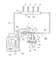
図1は本実施形態における燃料供給システム100の構造を模式的に示す図である。この図1に示すように、燃料供給システム100は、燃料タンク101から燃料を送り出す電動ポンプで成るフィードポンプ102と、そのフィードポンプ102によって送り出された燃料を加圧して各気筒(4気筒)のインジェクタ(燃料噴射弁)4,4,…に向けて吐出する高圧燃料ポンプ1とを備えている。
<First Embodiment>
-Fuel supply system-
FIG. 1 is a diagram schematically showing the structure of a
上記高圧燃料ポンプ1の概略構成としては(具体構成については、後で図3を用いて説明する)、シリンダ21、プランジャ23、加圧室22及び電磁スピル弁30を備えている。プランジャ23は、エンジンの排気カムシャフト110に取り付けられた駆動カム111の回転によって駆動され、シリンダ21内を往復移動する。このプランジャ23の往復移動により加圧室22の容積が拡大または縮小する。本実施形態では排気カムシャフト110の回転軸回りに180°の角度間隔をもって2つのカム山(カムノーズ)112,112が駆動カム111に形成されている。そして、このカムノーズ112,112によってプランジャ23が押し上げられて、このプランジャ23がシリンダ21内で移動するようになっている。尚、本実施形態に係るエンジンは4気筒型であるため、エンジンの1サイクル中、つまりクランクシャフトが2回転する間に、気筒毎に設けられたインジェクタ4から各1回ずつ、合計4回の燃料噴射が行われることになる。また、このエンジンでは、クランクシャフトが2回転する度に排気カムシャフト110は1回転する。よって、インジェクタ4からの燃料噴射は4回ずつ、高圧燃料ポンプ1からの吐出動作は2回ずつ、エンジンの1サイクル毎に行われるようになっている。
As a schematic configuration of the high-pressure fuel pump 1 (the specific configuration will be described later with reference to FIG. 3), a
上記加圧室22はプランジャ23及びシリンダ21によって区画されている。この加圧室22は、低圧燃料配管104を介してフィードポンプ102に連通しており、また、高圧燃料配管105を介してデリバリパイプ(蓄圧容器)106内に連通している。
The pressurizing
このデリバリパイプ106には、上記インジェクタ4,4,…が接続されていると共に、デリバリパイプ106内の燃料圧力(実燃圧)を検出する燃圧センサ161が配設されている。また、このデリバリパイプ106には、リリーフバルブ171を介してリターン配管172が接続されている。このリリーフバルブ171は、デリバリパイプ106内の燃料圧力が所定圧(例えば13MPa)を越えたときに開弁する。この開弁により、デリバリパイプ106に蓄えられた燃料の一部をリターン配管172を介して燃料タンク101に戻すようになっている。これにより、デリバリパイプ106内の燃料圧力の過上昇が防止される。また、上記リターン配管172と高圧燃料ポンプ1とは、燃料排出配管108(図1では破線で示している)によって接続されており、プランジャ23とシリンダ21との間隙から漏出した燃料がシールユニット5の上部の燃料収容室6に蓄積され、その後、この燃料収容室6に接続された上記燃料排出配管108に戻されるようになっている。
The
尚、低圧燃料配管104には、フィルタ141及びプレッシャレギュレータ142が設けられている。このプレッシャレギュレータ142は、低圧燃料配管104内の燃料圧力が所定圧(例えば0.4MPa)を越えたときに低圧燃料配管104内の燃料を燃料タンク101に戻すことによって、この低圧燃料配管104内の燃料圧力を所定圧以下に維持している。また、低圧燃料配管104には、パルセーションダンパ7が備えられており、このパルセーションダンパ7によって高圧燃料ポンプ1の作動時における低圧燃料配管104内の燃圧脈動が抑制されるようになっている。
Note that the low-
上記高圧燃料ポンプ1には、低圧燃料配管104と加圧室22との間を連通または遮断するための上記電磁スピル弁30が設けられている。この電磁スピル弁30は、駆動源となる電磁ソレノイド31を備えており、その電磁ソレノイド31への通電を制御することにより開閉動作する。電磁スピル弁30は、電磁ソレノイド31への通電が停止されているときにはコイルスプリング37の付勢力によって開弁する所謂ノーマルオープンタイプのものである。以下、この電磁スピル弁30の開閉動作について図2を参照しながら説明する。
The high-
先ず、電磁ソレノイド31に対する通電が停止された状態のときには、電磁スピル弁30がコイルスプリング37の付勢力によって開弁し、低圧燃料配管104と加圧室22とが連通した状態になる(図1に示す状態を参照)。この状態において、加圧室22の容積が増大する方向にプランジャ23が移動するとき(吸入行程)には、フィードポンプ102から送り出された燃料が低圧燃料配管104を経て加圧室22内に吸入される。
First, when the energization of the
一方、加圧室22の容積が収縮する方向にプランジャ23が移動するとき(加圧行程)において、電磁ソレノイド31への通電により電磁スピル弁30がコイルスプリング37の付勢力に抗して閉弁すると、低圧燃料配管104と加圧室22との間が遮断され、加圧室22内の燃料圧力が所定値に達した時点でチェック弁40が開放して、高圧の燃料が高圧燃料配管105を通じてデリバリパイプ106に向けて吐出される(このチェック弁40の構成については後述する)。
On the other hand, when the
そして、高圧燃料ポンプ1における燃料吐出量の調整は、加圧行程での電磁スピル弁30の閉弁期間を制御することによって行われる。即ち、電磁スピル弁30の閉弁開始時期を早めて閉弁期間を長くすると燃料吐出量が増加し、電磁スピル弁30の閉弁開始時期を遅らせて閉弁期間を短くすると燃料吐出量が減少するようになる。このように、高圧燃料ポンプ1の燃料吐出量を調整することにより、デリバリパイプ106内の燃料圧力が制御される。
The fuel discharge amount in the high-
ここで、高圧燃料ポンプ1の燃料吐出量(電磁スピル弁30の閉弁開始時期)を制御するための制御量であるポンプデューティDTについて説明する。 Here, the pump duty DT which is a control amount for controlling the fuel discharge amount of the high-pressure fuel pump 1 (the valve closing start timing of the electromagnetic spill valve 30) will be described.
このポンプデューティDTは、0〜100%という値の間で変化するものであって、電磁スピル弁30の閉弁期間に対応する排気カムシャフト110の駆動カム111のカム角度に関係した値である。
The pump duty DT varies between 0 and 100%, and is a value related to the cam angle of the
具体的には、駆動カム111のカム角度に関して、図2に示すように、電磁スピル弁30の最大閉弁期間に対応したカム角度(最大カム角度)をθ0とし、その最大閉弁期間の目標燃圧に対応するカム角度(目標カム角度)をθとすると、ポンプデューティDTは、最大カム角度θ0に対する目標カム角度θの割合(DT=θ/θ0)で表される。従って、ポンプデューティDTは、目標とする電磁スピル弁30の閉弁期間(閉弁開始時期)が最大閉弁期間に近づくほど100%に近い値となり、目標とする閉弁期間が「0」に近づくほど0%に近い値となる。
Specifically, with respect to the cam angle of the
そして、ポンプデューティDTが100%に近づくほど、ポンプデューティDTに基づいて調整される電磁スピル弁30の閉弁開始時期は早められ、電磁スピル弁30の閉弁期間は長くなる。その結果、高圧燃料ポンプ1の燃料吐出量が増加して実燃圧が上昇するようになる。また、ポンプデューティDTが0%に近づくほど、ポンプデューティDTに基づいて調整される電磁スピル弁30の閉弁開始時期は遅らされ、電磁スピル弁30の閉弁期間は短くなる。その結果、高圧燃料ポンプ1の燃料吐出量が減少して実燃圧が低下するようになる。尚、上記ポンプデューティDTの算出手順の詳細についてはここでは説明を省略する。
And as the pump duty DT approaches 100%, the valve closing start timing of the
−高圧燃料ポンプ1の具体構成−
次に、上記高圧燃料ポンプ1の具体構成について図3を用いて説明する。図3は高圧燃料ポンプ1の縦断面図である。この図3に示すように、本実施形態の高圧燃料ポンプ1は、ハウジング10内にポンプ部20、上記電磁スピル弁30及びチェック弁40を備えた構成となっている。
-Specific configuration of high-pressure fuel pump 1-
Next, a specific configuration of the high-
(ポンプ部20)
上記ポンプ部20は、上記シリンダ21、加圧室22、プランジャ23、リフタ24及びリフタガイド25を備えている。シリンダ21はハウジング10の中央部に形成され、その先端側(図3における上端側)に加圧室22が形成される。プランジャ23は円柱状であって、シリンダ21内にその軸線方向の摺動が可能に挿入されている。リフタ24は有底円筒状に形成されており、その内部に、プランジャ23の基端部、後述するリテーナ26及びコイルスプリング27等が収容される。リフタガイド25はハウジング10の下側に取り付けられた円筒状の部材であって、その内部に上記リフタ24が軸線方向へ摺動可能に収納されている。
(Pump unit 20)
The
上記プランジャ23の基端部にはリテーナ26が係合されている。具体的には、プランジャ23の基端部に小径部23aが設けられており、リテーナ26にはこの小径部23aの外径寸法に略一致する幅を有する溝26aが形成されていて、この溝26aに小径部23aが嵌め込まれることによってプランジャ23の基端部がリテーナ26に往復移動一体に係合されている。そして、上記ハウジング10の下面とリテーナ26との間にコイルスプリング27が圧縮状態で配置されている。つまり、このコイルスプリング27により、プランジャ23に対して下方への付勢力が付与されていると共に、リフタ24が駆動カム111に向けて付勢されている。尚、駆動カム111の外周面の中心位置(駆動カム111の回転軸方向の中心位置)とリフタ24の下面の中心点とは駆動カム111の回転軸方向に沿ってずらされ(偏心され)ており、これら両者は所謂オフセット配置されている。また、このオフセットの方向としては、駆動カム111の外周面とリフタ24の下面との間の摩擦力を利用してリフタ24が平面視において時計回り方向に回転するようにされている。
A
(電磁スピル弁30)
上記電磁スピル弁30は加圧室22に対向して配設され、上記電磁ソレノイド31、ボビン32、コア33、アーマチャ34、吸入弁35、ガイド部材36及びバルブシート部材13を備えている。電磁ソレノイド31はボビン32にリング状に巻装されたコイルで成り、コア33はボビン32の中心貫通孔に嵌合固定されている。アーマチャ34は吸入弁35の一端に固定された状態で、その一部がコア33と同軸上でボビン32の中心貫通孔に進入可能に配置されている。コア33及びアーマチャ34の各対向面には凹部がそれぞれ形成されており、それら凹部間にはコイルスプリング37が圧縮状態で収容されている。そして、このコイルスプリング37により、アーマチャ34が加圧室22側に向かって付勢されている。
(Electromagnetic spill valve 30)
The
上記吸入弁35はガイド部材36内の貫通孔に摺動可能に挿入されていると共に円板状の弁体35aが形成されている。
The
また、上記バルブシート部材13は、略円筒形状の部材であって、上記ハウジング10において加圧室22に連通する空間である燃料吸入空間14に嵌め込まれている。また、このバルブシート部材13には、上記ガイド部材36に対向し且つ中央部に燃料導入開口13bが形成された円板部13aと、この円板部13aに形成されている燃料導入開口13bの周縁から加圧室22側に向けてスリーブ形状(円筒形状)に突出したバルブシート13cとを備えている。そして、上記吸入弁35の弁体35aは、このバルブシート13cと対向するように上記バルブシート部材13の内部に位置している。
The
これにより、電磁ソレノイド31の非通電時には、コイルスプリング37の付勢力により、吸入弁35の弁体35aがバルブシート13cから離間されて、上記円板部13aに形成されている燃料導入開口13bが開放され、電磁スピル弁30は開弁状態となる(図3に示す状態)。この状態では、上記低圧燃料配管104と加圧室22との間で燃料が流通可能となっている。一方、図示しない電子制御装置から端子38を介して電磁ソレノイド31に通電されると、コア33、アーマチャ34及び電磁スピル弁30全体を支持する支持部材39により磁気回路が形成され、コイルスプリング37の付勢力に抗して、アーマチャ34がコア33側に移動する。これにより、吸入弁35が加圧室22とは反対側に移動し、その弁体35aがバルブシート13cに当接して、電磁スピル弁30は閉弁状態となる。この状態では、上記低圧燃料配管104と加圧室22とが遮断される。
Thus, when the
上記ハウジング10には、内部空間が上記燃料吸入空間14に連通する吸入管部材11が取り付けられている。そして、電磁スピル弁30の開弁状態で、プランジャ23が下降するとき、フィードポンプ102の作動により燃料タンク101から汲み上げられた低圧燃料が、フィルタ141、プレッシャレギュレータ142、パルセーションダンパ7、吸入管部材11及び燃料吸入空間14を経て加圧室22に吸入されるようになっている。
A
上記シリンダ21の先端側に形成された加圧室22は、シリンダ21の内径よりも大径に形成されている。そして、プランジャ23は、電磁スピル弁30の閉タイミング前または閉タイミングと同時に上昇移動され、電磁スピル弁30が閉弁した後に上死点に到達するようになっている。また、ハウジング10には燃料吐出通路12が形成されており、この燃料吐出通路12内に上記チェック弁40が配設されている。この燃料吐出通路12及びチェック弁40の軸心と上記吸入弁35の軸心とは水平方向に延びる同一軸上に配設されている。
The pressurizing
(チェック弁40)
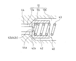
図3及び図4に示すように、上記チェック弁40は、燃料吐出通路12に嵌め込まれたスプリングベース体41と、燃料吐出通路12の内壁面に対して接離可能とされた吐出弁体としてのバルブ体42と、このバルブ体42を閉弁方向に向けて付勢するコイルスプリング(付勢手段)43とを備えている。
(Check valve 40)
As shown in FIGS. 3 and 4, the
具体的には、図4に示すように、上記燃料吐出通路12の形状としては、加圧室22に連通する比較的小径の小径通路12aと、上記スプリングベース体41、バルブ体42、コイルスプリング43が配設される空間であって比較的大径の大径通路12bと、これら小径通路12aと大径通路12bとの内壁面同士を連結するテーパ面により形成された拡径通路12cとを備えている。
Specifically, as shown in FIG. 4, the
上記スプリングベース体41は、円筒形状の部材であって、その外径寸法は上記大径通路12bの内径寸法に略一致しており、この大径通路12bに嵌め込まれて固定されている。また、このスプリングベース体41の前端面(拡径通路12c側の端面)は上記コイルスプリング43の一端が当接するスプリング座面として機能している。
The
上記バルブ体42は、有底円筒形状を有しており、その内部の底面に上記コイルスプリング43の一端が当接している。つまり、このバルブ体42とスプリングベース体41との間に上記コイルスプリング43が圧縮状態で介在されていることにより、バルブ体42はコイルスプリング43からの付勢力を受けている。そして、このバルブ体42の先端部(小径通路12a側の先端部)の外周縁は、上記拡径通路12cの内面形状(テーパ面形状)に略合致する外側傾斜面42aを備えている。このため、バルブ体42が上記コイルスプリング43の付勢力を受けて、上記外側傾斜面42aが拡径通路12cのテーパ面に当接することによって小径通路12aと大径通路12bとを遮断するようになっている。つまり、上記拡径通路12cのテーパ面が本発明でいう弁座部を構成している。
The
尚、このチェック弁40の下流側では燃料吐出通路12が上記高圧燃料配管105に接続されている。そして、加圧室22内から小径通路12aに亘る空間での燃料圧力が所定値を超えたとき、バルブ体42がコイルスプリング43の付勢力に抗して拡径通路12cのテーパ面から離間する位置に移動される。これにより、チェック弁40が開弁状態になって、燃料吐出通路12から圧送される高圧燃料が高圧燃料配管105を経てデリバリパイプ106に供給されるようになっている。
The
そして、本実施形態の特徴は、このチェック弁40及びその周辺部の構成にある。以下、具体的に説明する。
And the feature of this embodiment exists in the structure of this
上記チェック弁40のバルブ体42の中心部には、小径の開口42bが形成されている。この開口42bは、上記小径通路12aの内径寸法よりも小径に設定されている。また、この開口42bの内周面は、燃料流れ方向の下流側(小径通路12aから大径通路12bへ向かう側)に向かって次第に開口面積が縮小するように擂り鉢状に形成された内側傾斜面42cを備えている。
A small-
そして、本実施形態におけるチェック弁40にあっては、上記バルブ体42の中心部に形成されている上記開口42bを開閉するための弁体(微小隙間開閉体)となるニードル弁44が備えられている。このニードル弁44の先端部は、上記開口42bの内周面として形成されている内側傾斜面42cの傾斜角度に略合致する傾斜面44aを備え、先端側に向かって先細り形状となっている。一方、このニードル弁44の基端部は、図3に示すように上記加圧室22内を通過して上記電磁スピル弁30の弁体35aに一体的に連結されている。このため、このニードル弁44は、電磁スピル弁30の動作に連動し、弁体35aの進退移動に伴って軸心方向に沿って進退移動するようになっている。
The
詳しくは、電磁スピル弁30が開弁状態にある際のニードル弁44の先端位置は、図6に示すように、このニードル弁44の先端部がバルブ体42の開口42bに挿入されて、この開口42bを閉鎖するものの、バルブ体42に開弁方向への付勢力を付与することのない位置に設定される。つまり、チェック弁40の開放動作(バルブ体42の外側傾斜面42aが拡径通路12cのテーパ面から離間する動作)を行うことなしに開口42bを閉鎖する位置となる(ニードル弁44の第2の進退位置)。
Specifically, the tip position of the
一方、電磁スピル弁30が閉弁状態にある際のニードル弁44の先端位置は、図5に示すように、このニードル弁44の先端部がバルブ体42の開口42bから後退し、この開口42bの内縁部とニードル弁44の先端部との間で僅かな隙間(微小隙間)を形成する位置に設定される(ニードル弁44の第1の進退位置)。以上の構成により、本発明でいう微小隙間開閉手段が構成されている。また、ここで形成される微小隙間は、例えば、開口42bの内縁部とニードル弁44の先端部との間に1〜2mm程度の僅かな隙間として設定され、チェック弁40の上流側と下流側とに圧力差がある場合に、燃料が徐々に低圧側に流れ込む程度に設定されている。
On the other hand, the tip position of the
−チェック弁40の動作−
次に、上述の如く構成されたチェック弁40の動作について説明する。
-Operation of check valve 40-
Next, the operation of the
先ず、エンジンが駆動状態から停止状態になり、それに伴って高圧燃料ポンプ1が停止されると、それまで高圧燃料が高圧燃料配管105を経てデリバリパイプ106に供給されていたために、このデリバリパイプ106の内部空間は高圧状態となっている。このような状況で、上記電磁スピル弁30の電磁ソレノイド31への通電が開始され、図5に示すように、吸入弁35の弁体35aがバルブシート13c側に引き込まれて、このバルブシート13cに当接し、電磁スピル弁30は閉弁状態とされる。この弁体35aの移動に連動し、上記ニードル弁44は、その先端部がバルブ体42の開口42bから後退し、この開口42bの内縁部とニードル弁44の先端部との間で僅かな隙間が形成されることになる。そのため、チェック弁40の下流側空間である高圧燃料配管105と加圧室22とは、この微小隙間によって連通した状態となり、この微小隙間から加圧室22側に燃料が徐々に戻されていくことによってデリバリパイプ106の内圧は低下していく。その結果、上記インジェクタ4,4,…から気筒内への燃料漏れが防止される。
First, when the engine is changed from the drive state to the stop state and the high-
そして、エンジンが駆動され、それに伴って高圧燃料ポンプ1も始動された際において、上記プランジャ23が下降する吸入行程が行われる際には、電磁ソレノイド31の通電が解除され(非通電状態となり)、図6に示すように、コイルスプリング37の付勢力により、吸入弁35の弁体35aがバルブシート13cから離間されて、電磁スピル弁30は開弁状態となる。この弁体35aの移動に連動し、上記ニードル弁44は、その先端部がバルブ体42の開口42bに向けて前進し、このニードル弁44の先端部によってバルブ体42の開口42bが閉塞される。そのため、チェック弁40の下流側空間である高圧燃料配管105と加圧室22とは遮断された状態となり、この吸入行程では、高圧燃料配管105から加圧室22に向けて燃料が逆流することが阻止され、この加圧室22には、フィードポンプ102から供給される燃料のみが導入されることになる。尚、この吸入行程にあっては、加圧室22内の圧力は低いため(例えばフィードポンプ102の吐出圧程度の低圧になっているため)バルブ体42が開弁方向へ移動することはない。その結果、高圧燃料ポンプ1の吐出効率を高く維持することができ、また、燃料の逆流に起因するキャビテーション・エロージョンの発生を回避することもできる。
When the engine is driven and the high-
尚、上記プランジャ23が上昇する加圧行程が行われる際には、所定タイミングで、上記電磁ソレノイド31に通電されて電磁スピル弁30が閉弁状態となり(図5参照)、加圧室22内の燃料圧力が所定値に達した時点で、チェック弁40が開放する。つまり、加圧室22内から小径通路12aに亘る空間での燃料圧力が所定値を超えたとき、バルブ体42がコイルスプリング43の付勢力に抗して拡径通路12cのテーパ面から離間する位置に移動し、チェック弁40が開弁状態になって、燃料吐出通路12から圧送される高圧燃料が高圧燃料配管105を経てデリバリパイプ106に供給されることになる。この際、バルブ体42はニードル弁44の先端部からも後退移動することになるので、上記開口42bの内縁部とニードル弁44の先端部との間で形成される隙間の開放面積が拡大することになり、バルブ体42と拡径通路12cのテーパ面との間で形成される吐出通路ばかりでなく、バルブ体42に形成されている開口42bをも利用して高圧燃料の吐出が可能な状態となり、燃料吐出に対する圧力損失を低減することができる。尚、この加圧行程の初期段階において、加圧室22内の燃料圧力が所定値に達するまでの間、つまり、チェック弁40が未だ開放していない状態では、上記開口42bは開放された状態にあるが、この開口42bにより形成されている隙間は微小であるため、ここからの燃料の流出量は僅かであり、加圧室22内の圧力上昇に対して悪影響を与えることは殆どない。
When a pressurizing stroke for raising the
以上説明したように、本実施形態によれば、ポンプ停止後におけるインジェクタ4,4,…からの燃料漏れを防止可能としながらも、吸入行程時における燃料の逆流を阻止して高い吐出効率を有する高圧燃料ポンプ1を実現することが可能である。
As described above, according to the present embodiment, it is possible to prevent the fuel leakage from the injectors 4, 4,... After the pump is stopped, but to prevent the reverse flow of the fuel during the intake stroke and to have high discharge efficiency. It is possible to realize the high-
また、本実施形態の構成によれば、電磁スピル弁30及びチェック弁40のうち一方が開放されると他方が閉鎖されるようになっているため、デリバリパイプ106の内部空間と燃料タンク101とが直接的に連通する状態となることがない。このため、デリバリパイプ106の内部圧力が燃料タンク101の内部圧力程度まで低下してしまうといった状況は生じないことになる。その結果、エンジン始動後にはデリバリパイプ106の内部圧力を短時間のうちに必要圧力(例えば上記13MPa)まで上昇させることができて、エンジンの始動性を良好に確保することができる。
Further, according to the configuration of the present embodiment, when one of the
<第2実施形態>
次に、第2実施形態について説明する。
Second Embodiment
Next, a second embodiment will be described.
上述した第1実施形態における高圧燃料ポンプ1の電磁スピル弁30は、電磁ソレノイド31への通電が停止されているときにはコイルスプリング37の付勢力によって開弁する所謂ノーマルオープンタイプのものであった。
The
本実施形態は、それに代えて、電磁ソレノイド31への通電が停止されているときには閉弁する所謂ノーマルクローズタイプの電磁スピル弁30を備えた高圧燃料ポンプ1に本発明を適用した場合について説明する。つまり、本実施形態に係る高圧燃料ポンプ1では、電磁スピル弁30の吸入弁35に対して閉弁方向への付勢力がコイルスプリング等によって与えられた構成となっており、電磁ソレノイド31へ通電が行われた際には、この付勢力に抗して吸入弁35が開弁方向へ移動する構成となっている。その他の構成は上述した第1実施形態のものと同様であるので、ここでの説明は省略する。
In this embodiment, instead, a case will be described in which the present invention is applied to a high-
このように構成された高圧燃料ポンプ1におけるチェック弁40の動作について以下に説明する。
The operation of the
エンジンが駆動状態から停止状態になり、それに伴って高圧燃料ポンプ1が停止されると、上記電磁スピル弁30の電磁ソレノイド31への通電が解除され(非通電状態となり)、図5に示すように、上記付勢力により吸入弁35の弁体35aがバルブシート13c側に引き込まれて、このバルブシート13cに当接し、電磁スピル弁30は閉弁状態とされる。この弁体35aの移動に連動し、上記ニードル弁44は、その先端部がバルブ体42の開口42bから後退し、この開口42bの内縁部とニードル弁44の先端部との間で僅かな隙間が形成されることになる。これにより、上述した第1実施形態の場合と同様に、この微小隙間から加圧室22側に燃料が徐々に戻されていくことによってデリバリパイプ106の内圧は低下していく。その結果、上記インジェクタ4,4,…から気筒内への燃料漏れが防止される。
When the engine is switched from the drive state to the stop state and the high-
一方、エンジンが駆動され、それに伴って高圧燃料ポンプ1も始動された際において、上記プランジャ23が下降する吸入行程が行われる際には、電磁ソレノイド31への通電が行われ、図6に示すように、上記付勢力に抗して、吸入弁35の弁体35aがバルブシート13cから離間されて、電磁スピル弁30は開弁状態となる。この弁体35aの移動に連動し、上記ニードル弁44は、その先端部がバルブ体42の開口42bに向けて前進し、このニードル弁44の先端部によってバルブ体42の開口42bが閉塞される。これにより、上述した第1実施形態の場合と同様に、吸入行程では、高圧燃料配管105から加圧室22に向けて燃料が逆流することが阻止され、この加圧室22には、フィードポンプ102から供給される燃料のみが導入されることになる。その結果、高圧燃料ポンプ1の吐出効率を高く維持することができ、また、燃料の逆流に起因するキャビテーション・エロージョンの発生が回避される。
On the other hand, when the engine is driven and the high
尚、上記プランジャ23が上昇する加圧行程が行われる際には、所定タイミングで、上記電磁ソレノイド31への通電が解除されて電磁スピル弁30が閉弁状態となり(図5参照)、加圧室22内の燃料圧力が所定値に達した時点で、チェック弁40が開放し、燃料吐出通路12から圧送される高圧燃料が高圧燃料配管105を経てデリバリパイプ106に供給される。この場合にも、バルブ体42はニードル弁44の先端部から後退移動することになるので、上記開口42bの内縁部とニードル弁44の先端部との間で形成される隙間の開放面積が拡大することになり、バルブ体42と拡径通路12cのテーパ面との間で形成される吐出通路ばかりでなく、バルブ体42に形成されている開口42bをも利用して高圧燃料の吐出が可能な状態となり、燃料吐出に対する圧力損失を低減することができる。
When a pressurizing stroke for raising the
このように、ノーマルクローズタイプの電磁スピル弁30を備えた高圧燃料ポンプ1に本発明を適用した場合にも上述した第1実施形態の場合と同様の効果を奏することができる。
Thus, even when the present invention is applied to the high-
<第3実施形態>
次に、第3実施形態について説明する。
<Third Embodiment>
Next, a third embodiment will be described.
上述した第1実施形態及び第2実施形態では、高圧燃料ポンプ1の停止時には、上記ニードル弁44をバルブ体42の開口42bから後退させて、この開口42bの内縁部とニードル弁44の先端部との間に微小隙間を常時形成するようにしていた。
In the first and second embodiments described above, when the high-
本実施形態は、それに代えて、高圧燃料ポンプ1が駆動状態から停止状態になった時点にあっては、上記ニードル弁44をバルブ体42の開口42bから後退させて、この開口42bの内縁部とニードル弁44の先端部との間に微小隙間を形成しておき、所定タイミングで、ニードル弁44により開口42bを閉塞して上記微小隙間を形成しないようにするものである。
In the present embodiment, instead, when the high-
つまり、エンジンが駆動状態から停止状態になり、それに伴って高圧燃料ポンプ1が停止されると、図5に示すように、上記ニードル弁44の先端部をバルブ体42の開口42bから後退させて、この開口42bの内縁部とニードル弁44の先端部との間で僅かな隙間を形成する。これにより、この微小隙間から加圧室22側に燃料が徐々に戻されていくことによってデリバリパイプ106の内圧は低下していく。
That is, when the engine is stopped from the driving state and the high
そして、上記デリバリパイプ106に取り付けられている燃圧センサ161によって検出されるデリバリパイプ106内部の燃料圧力の値が、上記インジェクタ4,4,…から気筒内への燃料漏れが防止できる値まで低下した時点(例えば5Mpaとなった時点)で、ニードル弁44を前進させて、開口42bを閉塞して上記微小隙間を形成しないようにしている。これにより、高圧燃料配管105と加圧室22とは遮断されることになり、加圧室22側への燃料戻りは停止されることになる。つまり、デリバリパイプ106内の圧力は、上記インジェクタ4,4,…からの燃料漏れが防止できる範囲内において比較的高い値に維持され続けることになる。このため、デリバリパイプ106内の圧力が必要以上に低下してしまうといった状況を回避でき、エンジンの再始動時には、デリバリパイプ106内の圧力を短時間のうちに必要圧力(例えば上記13MPa)まで上昇させることができて、エンジンの始動性を良好に確保することができる。
Then, the value of the fuel pressure inside the
特に、本実施形態の構成は、ノーマルオープンタイプの電磁スピル弁30を備えた高圧燃料ポンプ1に適用した場合に有効である。何故なら、ノーマルオープンタイプの電磁スピル弁30の場合、上記第1実施形態で説明したように、上記ニードル弁44の先端部をバルブ体42の開口42bから後退させて微小隙間を形成しておくためには、電磁ソレノイド31への通電を継続的に行っておくことが必要である。そして、高圧燃料ポンプ1の停止時に常時微小隙間を形成しておくためには、電磁ソレノイド31への通電を長期間に亘って継続する必要があり、消費電力の増大に繋がってしまう。
In particular, the configuration of the present embodiment is effective when applied to the high-
本実施形態では、燃圧センサ161によって検出されるデリバリパイプ106内部の燃料圧力の値が、上記インジェクタ4,4,…から気筒内への燃料漏れが防止できる値まで低下した時点で、ニードル弁44を前進させて、開口42bを閉塞して上記微小隙間を形成しないようにしている。つまり、電磁ソレノイド31への通電を解除している。このため、長期間に亘ってエンジンが駆動しない状況であっても、ニードル弁44を作動させておく必要はなくなり、消費電力の削減を図ることができる。
In the present embodiment, when the value of the fuel pressure inside the
−他の実施形態−
上述した各実施形態では、本発明を自動車に搭載された筒内直噴型4気筒ガソリンエンジンに適用した場合について説明した。本発明はこれに限らず、例えば筒内直噴型6気筒ガソリンエンジンなど他の任意の気筒数のガソリンエンジンに適用可能である。また、ガソリンエンジンに限らず、ディーゼルエンジン等の他の内燃機関にも本発明は適用可能である。更には、本発明が適用可能なエンジンは、自動車用のエンジンに限るものでもない。
-Other embodiments-
Each embodiment mentioned above demonstrated the case where this invention was applied to the in-cylinder direct injection type | mold 4-cylinder gasoline engine mounted in the motor vehicle. The present invention is not limited to this, and can be applied to a gasoline engine having any other number of cylinders such as a direct injection type 6-cylinder gasoline engine. Further, the present invention is not limited to a gasoline engine, but can be applied to other internal combustion engines such as a diesel engine. Furthermore, the engine to which the present invention is applicable is not limited to an automobile engine.
また、上記各実施形態における高圧燃料ポンプ1では、排気カムシャフト110に取り付けられた駆動カム111の回転によってプランジャ23が駆動される構成としたが、吸気カムシャフトに取り付けられた駆動カムの回転によってプランジャ23が駆動される構成としてもよい。
In the high-
更に、本発明は、2つのカムノーズ112,112を有する駆動カム111を備えたものに限らず、その他の個数のカムノーズを有する駆動カムを備えたものにも適用可能である。
Furthermore, the present invention is not limited to the one provided with the
また、上記各実施形態における高圧燃料ポンプ1はプランジャポンプであったが、その他の容積形ポンプ(例えば、ピストンポンプやベーンポンプ等)に対しても本発明は適用可能である。
In addition, the high-
また、上記各実施形態では、電磁スピル弁30を備えた高圧燃料ポンプ1に本発明を適用し、且つこの電磁スピル弁30の吸入弁35とチェック弁40とを同一軸線上に配設したものであった。本発明はこれに限らず、電磁スピル弁30以外の開閉弁を吸入側に備えさせ、この開閉弁と上記ニードル弁44とを連動させる構成としてもよい。また、電磁スピル弁30の開閉駆動力をニードル弁44に伝達するための構成としては、上記各実施形態の如く電磁スピル弁30の弁体35aにニードル弁44を直接的に連結するものに限らず、リンク機構などを介してニードル弁44に開閉駆動力を伝達する構成としてもよい。この場合には、電磁スピル弁30の吸入弁35とチェック弁40とを同一軸線上に配設する必要がなくなるので、各弁のレイアウト自由度の向上を図ることができる。
In the above embodiments, the present invention is applied to the high-
また、上述した各実施形態では、電磁スピル弁30に連動してニードル弁44を作動させるようにしたが、このニードル弁44に専用の駆動源(電磁ソレノイドや電動モータ)を備えさせ、この駆動源の駆動によって上述した各実施形態の如くニードル弁44を作動させる構成も本発明の技術的思想の範疇である。
In each of the above-described embodiments, the
1 高圧燃料ポンプ
4 インジェクタ(燃料噴射弁)
12 燃料吐出通路
12c 拡径通路(弁座部)
21 シリンダ
22 加圧室
23 プランジャ
30 電磁スピル弁
31 電磁ソレノイド(駆動源)
42 バルブ体(吐出弁体)
42b 開口
43 コイルスプリング(付勢手段)
44 ニードル弁(微小隙間開閉体)
1 High-pressure fuel pump 4 Injector (fuel injection valve)
12
21
42 Valve body (discharge valve body)
44 Needle valve (micro gap opening / closing body)
Claims (3)
ポンプ駆動状態からポンプ停止状態になった際に吐出弁体下流側空間と上記加圧室とを微小隙間によって連通させる一方、ポンプ駆動時における少なくとも上記吸入行程ではこの微小隙間を閉塞する微小隙間開閉手段が備えられており、
上記吐出弁体には、吐出弁体下流側空間と加圧室とを連通可能とする開口が形成されていて、
上記微小隙間開閉手段は、上記吐出弁体の開口から後退し、この開口を開放させて吐出弁体下流側空間と加圧室とを連通させる第1の進退位置と、上記吐出弁体の開口に向けて前進し、この開口を閉塞させて吐出弁体下流側空間と加圧室とを遮断する第2の進退位置との間で進退移動可能な微小隙間開閉体が設けられており、
この微小隙間開閉体は、電磁ソレノイドを駆動源としてこの電磁ソレノイドの通電/非通電によって上記第1の進退位置と第2の進退位置との間で移動して上記開口の内縁部と微小隙間開閉体との間で形成される微小隙間を開閉する構成となっていることを特徴とする燃料ポンプ。 A pressurizing chamber for pressurizing the fuel, and a discharge valve body disposed on the discharge side of the pressurizing chamber and provided with a biasing force in the valve closing direction. When the pressure in the pressurizing chamber reaches a predetermined pressure or higher in the pressurizing stroke, the discharge valve body moves in the valve opening direction against the urging force, and the fuel is directed from the pressurizing chamber toward the fuel injection valve. In a fuel pump configured to discharge
While communicating by small gap and a discharge valve body downstream space and said pressurizing chamber when changed from pump drive state to a pump stopped state, closes the Yoko small gap at least the intake stroke during pump driving small A gap opening / closing means is provided ,
The discharge valve body is formed with an opening that allows communication between the discharge valve body downstream space and the pressurizing chamber,
The minute gap opening / closing means retracts from the opening of the discharge valve body, opens the opening to communicate the downstream space of the discharge valve body and the pressurizing chamber, and the opening of the discharge valve body. A minute gap opening / closing body is provided that can move forward and backward between a second advance / retreat position that closes the opening and closes the discharge valve body downstream space and the pressurizing chamber by moving forward toward
The minute gap opening / closing body is moved between the first advance / retreat position and the second advance / retreat position by energization / non-energization of the electromagnetic solenoid using an electromagnetic solenoid as a driving source, and the minute gap opening / closing body is opened and closed. A fuel pump characterized by being configured to open and close a minute gap formed between the body and the body .
上記加圧室は、シリンダとこのシリンダ内を往復動するプランジャとにより区画形成されており、The pressurizing chamber is defined by a cylinder and a plunger that reciprocates in the cylinder.
上記加圧室の吸入側には上記電磁ソレノイドの作動により開閉動作が可能なスピル弁が備えられ、上記加圧室の容積を縮小する方向にプランジャが移動する加圧行程時にスピル弁の開閉動作を制御することによりポンプ圧送量の調量を行う構成となっている一方、A spill valve that can be opened and closed by the operation of the electromagnetic solenoid is provided on the suction side of the pressurizing chamber, and the spill valve is opened and closed during a pressurizing stroke in which the plunger moves in a direction to reduce the volume of the pressurizing chamber. While it is configured to adjust the pumping amount by controlling
上記微小隙間開閉手段の微小隙間開閉体は、上記スピル弁に連結されていて、スピル弁の開放動作に連動して上記第2の進退位置となり、スピル弁の閉鎖動作に連動して上記第1の進退位置となる構成とされていることを特徴とする燃料ポンプ。The minute gap opening / closing body of the minute gap opening / closing means is connected to the spill valve, and is moved to the second advance / retreat position in conjunction with the opening operation of the spill valve, and is linked to the closing operation of the spill valve. A fuel pump characterized in that the fuel pump is configured to be in a forward / backward position.
上記吐出弁体は、加圧室吐出側の吐出通路に形成された弁座部に対して付勢手段の付勢力を受けて当接されて吐出通路を閉鎖可能となっていると共に、加圧行程において加圧室内の圧力が所定圧力以上に達した場合に上記付勢手段の付勢力に抗して弁座部から後退移動することにより吐出通路を開放して加圧室から燃料が吐出されるようになっている一方、The discharge valve body receives the urging force of the urging means against the valve seat portion formed in the discharge passage on the discharge side of the pressurizing chamber so as to be able to close the discharge passage. In the stroke, when the pressure in the pressurizing chamber reaches a predetermined pressure or more, the discharge passage is opened by retreating from the valve seat portion against the biasing force of the biasing means, and fuel is discharged from the pressurizing chamber. On the other hand,
上記吸入行程において、微小隙間開閉体が上記第2の進退位置にあって吐出弁体の開口が閉塞されている状態から、上記加圧行程となって微小隙間開閉体が上記第1の進退位置となり、加圧室内の圧力が所定圧力以上に達して、吐出弁体が、弁座部から後退移動するのに伴って微小隙間開閉体から後退し、これによって吐出弁体の開口からも燃料が吐出される構成となっていることを特徴とする燃料ポンプ。In the suction stroke, from the state where the minute gap opening / closing body is in the second forward / backward position and the opening of the discharge valve body is closed, the minute gap opening / closing body is moved to the first forward / backward position in the pressure stroke. Thus, as the pressure in the pressurizing chamber reaches a predetermined pressure or more, the discharge valve body moves backward from the valve seat portion, so that the fuel is also discharged from the opening of the discharge valve body. A fuel pump characterized by being configured to be discharged.
Priority Applications (6)
| Application Number | Priority Date | Filing Date | Title |
|---|---|---|---|
| JP2007206185A JP4353288B2 (en) | 2007-08-08 | 2007-08-08 | Fuel pump |
| US12/672,043 US8911218B2 (en) | 2007-08-08 | 2008-07-31 | Fuel pump |
| AT08791967T ATE547620T1 (en) | 2007-08-08 | 2008-07-31 | FUEL PUMP |
| PCT/JP2008/063752 WO2009020039A1 (en) | 2007-08-08 | 2008-07-31 | Fuel pump |
| CN2008801023291A CN101779033B (en) | 2007-08-08 | 2008-07-31 | Fuel pump |
| EP20080791967 EP2187038B1 (en) | 2007-08-08 | 2008-07-31 | Fuel pump |
Applications Claiming Priority (1)
| Application Number | Priority Date | Filing Date | Title |
|---|---|---|---|
| JP2007206185A JP4353288B2 (en) | 2007-08-08 | 2007-08-08 | Fuel pump |
Publications (2)
| Publication Number | Publication Date |
|---|---|
| JP2009041420A JP2009041420A (en) | 2009-02-26 |
| JP4353288B2 true JP4353288B2 (en) | 2009-10-28 |
Family
ID=40341273
Family Applications (1)
| Application Number | Title | Priority Date | Filing Date |
|---|---|---|---|
| JP2007206185A Expired - Fee Related JP4353288B2 (en) | 2007-08-08 | 2007-08-08 | Fuel pump |
Country Status (6)
| Country | Link |
|---|---|
| US (1) | US8911218B2 (en) |
| EP (1) | EP2187038B1 (en) |
| JP (1) | JP4353288B2 (en) |
| CN (1) | CN101779033B (en) |
| AT (1) | ATE547620T1 (en) |
| WO (1) | WO2009020039A1 (en) |
Families Citing this family (46)
| Publication number | Priority date | Publication date | Assignee | Title |
|---|---|---|---|---|
| JP5514564B2 (en) * | 2010-01-25 | 2014-06-04 | 本田技研工業株式会社 | Fuel supply device |
| KR101171995B1 (en) | 2010-04-06 | 2012-08-08 | (주)모토닉 | Gasoline Direct Injection Pump |
| JP5530876B2 (en) * | 2010-09-14 | 2014-06-25 | 日立オートモティブシステムズ株式会社 | High pressure fuel supply pump |
| ITRM20110203A1 (en) * | 2011-04-21 | 2012-10-22 | Icomet Spa | REDUCER PRESSURE REGULATOR FOR METHANE SUPPLY OR OTHER SIMILAR COMBUSTIBLE FUELS OF INTERNAL COMBUSTION ENGINES |
| JP5537498B2 (en) | 2011-06-01 | 2014-07-02 | 日立オートモティブシステムズ株式会社 | High pressure fuel supply pump with electromagnetic suction valve |
| DE112011105591B4 (en) * | 2011-09-06 | 2017-03-16 | Toyota Jidosha Kabushiki Kaisha | Fuel pump and fuel delivery system for internal combustion engine |
| DE112011105711B4 (en) * | 2011-10-06 | 2019-05-23 | Toyota Jidosha Kabushiki Kaisha | Control device for internal combustion engine |
| JP5677329B2 (en) * | 2012-01-20 | 2015-02-25 | 日立オートモティブシステムズ株式会社 | High pressure fuel supply pump with electromagnetically driven suction valve |
| US9989026B2 (en) * | 2012-02-17 | 2018-06-05 | Ford Global Technologies, Llc | Fuel pump with quiet rotating suction valve |
| KR101905553B1 (en) * | 2012-10-31 | 2018-11-21 | 현대자동차 주식회사 | Control system and control method of gasoline direct injection engine |
| US9422898B2 (en) * | 2013-02-12 | 2016-08-23 | Ford Global Technologies, Llc | Direct injection fuel pump |
| JP6221410B2 (en) * | 2013-06-27 | 2017-11-01 | トヨタ自動車株式会社 | High pressure fuel pump |
| DE102013215275A1 (en) * | 2013-08-02 | 2015-02-05 | Robert Bosch Gmbh | High-pressure fuel pump, with an exhaust valve |
| EP3587790B1 (en) * | 2014-04-25 | 2023-03-08 | Hitachi Astemo, Ltd. | High-pressure fuel supply pump |
| JP6421701B2 (en) * | 2015-06-10 | 2018-11-14 | 株式会社デンソー | High pressure pump |
| JP6555055B2 (en) * | 2015-09-28 | 2019-08-07 | 株式会社デンソー | valve |
| JP6047648B2 (en) * | 2015-11-25 | 2016-12-21 | 日立オートモティブシステムズ株式会社 | High pressure fuel supply pump with electromagnetic suction valve |
| KR101877299B1 (en) * | 2016-04-07 | 2018-07-11 | (주)모토닉 | Control apparatus and method of flow control valve for high pressure fuel pump |
| JP6569589B2 (en) * | 2016-04-28 | 2019-09-04 | 株式会社デンソー | High pressure pump |
| US10274231B2 (en) * | 2016-07-19 | 2019-04-30 | Haier Us Appliance Solutions, Inc. | Caloric heat pump system |
| US11009282B2 (en) | 2017-03-28 | 2021-05-18 | Haier Us Appliance Solutions, Inc. | Refrigerator appliance with a caloric heat pump |
| US11022348B2 (en) | 2017-12-12 | 2021-06-01 | Haier Us Appliance Solutions, Inc. | Caloric heat pump for an appliance |
| DE112018005595T5 (en) * | 2017-12-26 | 2020-07-30 | Hitachi Automotive Systems, Ltd. | Fuel supply pump |
| DE102019203967A1 (en) * | 2018-03-27 | 2019-10-02 | Keihin Corporation | VALVE UNIT FASTENING STRUCTURE AND FLUID PUMP WHICH USES SELF |
| US10782051B2 (en) | 2018-04-18 | 2020-09-22 | Haier Us Appliance Solutions, Inc. | Magneto-caloric thermal diode assembly |
| US10830506B2 (en) | 2018-04-18 | 2020-11-10 | Haier Us Appliance Solutions, Inc. | Variable speed magneto-caloric thermal diode assembly |
| US10648704B2 (en) | 2018-04-18 | 2020-05-12 | Haier Us Appliance Solutions, Inc. | Magneto-caloric thermal diode assembly |
| US10876770B2 (en) | 2018-04-18 | 2020-12-29 | Haier Us Appliance Solutions, Inc. | Method for operating an elasto-caloric heat pump with variable pre-strain |
| US10648705B2 (en) | 2018-04-18 | 2020-05-12 | Haier Us Appliance Solutions, Inc. | Magneto-caloric thermal diode assembly |
| US11054176B2 (en) | 2018-05-10 | 2021-07-06 | Haier Us Appliance Solutions, Inc. | Magneto-caloric thermal diode assembly with a modular magnet system |
| US11015842B2 (en) | 2018-05-10 | 2021-05-25 | Haier Us Appliance Solutions, Inc. | Magneto-caloric thermal diode assembly with radial polarity alignment |
| US10989449B2 (en) | 2018-05-10 | 2021-04-27 | Haier Us Appliance Solutions, Inc. | Magneto-caloric thermal diode assembly with radial supports |
| US11092364B2 (en) | 2018-07-17 | 2021-08-17 | Haier Us Appliance Solutions, Inc. | Magneto-caloric thermal diode assembly with a heat transfer fluid circuit |
| US10684044B2 (en) | 2018-07-17 | 2020-06-16 | Haier Us Appliance Solutions, Inc. | Magneto-caloric thermal diode assembly with a rotating heat exchanger |
| WO2020022076A1 (en) * | 2018-07-27 | 2020-01-30 | 日立オートモティブシステムズ株式会社 | Fuel pump |
| CN113167201B (en) * | 2018-12-07 | 2023-05-02 | 斯坦蒂内有限责任公司 | Inlet control valve for high pressure fuel pump |
| US11193697B2 (en) | 2019-01-08 | 2021-12-07 | Haier Us Appliance Solutions, Inc. | Fan speed control method for caloric heat pump systems |
| US11149994B2 (en) | 2019-01-08 | 2021-10-19 | Haier Us Appliance Solutions, Inc. | Uneven flow valve for a caloric regenerator |
| US11274860B2 (en) | 2019-01-08 | 2022-03-15 | Haier Us Appliance Solutions, Inc. | Mechano-caloric stage with inner and outer sleeves |
| US11168926B2 (en) | 2019-01-08 | 2021-11-09 | Haier Us Appliance Solutions, Inc. | Leveraged mechano-caloric heat pump |
| US11112146B2 (en) | 2019-02-12 | 2021-09-07 | Haier Us Appliance Solutions, Inc. | Heat pump and cascaded caloric regenerator assembly |
| JP6886483B2 (en) * | 2019-03-15 | 2021-06-16 | 住友理工株式会社 | connector |
| US11015843B2 (en) | 2019-05-29 | 2021-05-25 | Haier Us Appliance Solutions, Inc. | Caloric heat pump hydraulic system |
| DE102019116353B4 (en) * | 2019-06-17 | 2020-12-24 | Man Energy Solutions Se | Fuel pump |
| WO2020262217A1 (en) * | 2019-06-27 | 2020-12-30 | 日立オートモティブシステムズ株式会社 | High-pressure fuel pump and electromagnetic valve thereof |
| EP4350139A1 (en) | 2022-10-06 | 2024-04-10 | Marelli Europe S.p.A. | Method to control a fuel injection system |
Family Cites Families (20)
| Publication number | Priority date | Publication date | Assignee | Title |
|---|---|---|---|---|
| JPS5045122A (en) * | 1973-08-22 | 1975-04-23 | ||
| US3986795A (en) * | 1973-08-22 | 1976-10-19 | Caterpillar Tractor Co. | Fuel injection assembly |
| DE3115909A1 (en) * | 1981-04-22 | 1982-11-04 | M.A.N. Maschinenfabrik Augsburg-Nürnberg AG, 8900 Augsburg | "FUEL PUMP" |
| US4706705A (en) * | 1986-04-01 | 1987-11-17 | The Lee Company | Check valve |
| JPH0455254Y2 (en) | 1988-01-18 | 1992-12-25 | ||
| JPH07145763A (en) * | 1993-11-25 | 1995-06-06 | Nippondenso Co Ltd | Solenoid valve for fuel injection device regulation |
| JPH08232686A (en) * | 1995-02-23 | 1996-09-10 | Nippondenso Co Ltd | Method and device for controlling fuel injection pump |
| JPH09112408A (en) * | 1995-10-19 | 1997-05-02 | Hitachi Ltd | Fuel pump |
| JP3237549B2 (en) * | 1996-11-25 | 2001-12-10 | トヨタ自動車株式会社 | High pressure fuel supply system for internal combustion engine |
| JP2001050174A (en) * | 1999-08-03 | 2001-02-23 | Hitachi Ltd | Fuel supply pump |
| JP2001182597A (en) * | 1999-12-24 | 2001-07-06 | Hitachi Ltd | High-pressure fuel pump controller, and direct injection engine controller |
| JP3786002B2 (en) | 2001-12-14 | 2006-06-14 | トヨタ自動車株式会社 | High pressure fuel supply device for internal combustion engine |
| JP3823060B2 (en) * | 2002-03-04 | 2006-09-20 | 株式会社日立製作所 | High pressure fuel supply pump |
| DE10251014A1 (en) * | 2002-11-02 | 2004-05-19 | Robert Bosch Gmbh | Fuel dispensing unit for fuel injection system for internal combustion engine has shutoff sleeve in interior of valve piston and valve piston and shutoff sleeve form shutoff device |
| JP4036153B2 (en) * | 2003-07-22 | 2008-01-23 | 株式会社日立製作所 | Damper mechanism and high-pressure fuel supply pump |
| JP4120630B2 (en) | 2004-09-24 | 2008-07-16 | トヨタ自動車株式会社 | High pressure fuel supply device for internal combustion engine and design method thereof |
| JP4478944B2 (en) * | 2004-12-17 | 2010-06-09 | 株式会社デンソー | Fluid metering valve and fuel injection pump using the same |
| JP2006207451A (en) | 2005-01-27 | 2006-08-10 | Toyota Motor Corp | Fuel pump and delivery valve equipped in fuel pump |
| JP4455470B2 (en) * | 2005-10-19 | 2010-04-21 | 日立オートモティブシステムズ株式会社 | Controller for high pressure fuel pump and normally closed solenoid valve of high pressure fuel pump |
| JP4678065B2 (en) * | 2009-02-25 | 2011-04-27 | 株式会社デンソー | Damper device, high-pressure pump using the same, and manufacturing method thereof |
-
2007
- 2007-08-08 JP JP2007206185A patent/JP4353288B2/en not_active Expired - Fee Related
-
2008
- 2008-07-31 WO PCT/JP2008/063752 patent/WO2009020039A1/en active Application Filing
- 2008-07-31 US US12/672,043 patent/US8911218B2/en not_active Expired - Fee Related
- 2008-07-31 CN CN2008801023291A patent/CN101779033B/en not_active Expired - Fee Related
- 2008-07-31 EP EP20080791967 patent/EP2187038B1/en not_active Not-in-force
- 2008-07-31 AT AT08791967T patent/ATE547620T1/en active
Also Published As
| Publication number | Publication date |
|---|---|
| US20110129363A1 (en) | 2011-06-02 |
| ATE547620T1 (en) | 2012-03-15 |
| WO2009020039A1 (en) | 2009-02-12 |
| CN101779033A (en) | 2010-07-14 |
| EP2187038A1 (en) | 2010-05-19 |
| CN101779033B (en) | 2012-05-30 |
| JP2009041420A (en) | 2009-02-26 |
| EP2187038A4 (en) | 2011-03-02 |
| EP2187038B1 (en) | 2012-02-29 |
| US8911218B2 (en) | 2014-12-16 |
Similar Documents
| Publication | Publication Date | Title |
|---|---|---|
| JP4353288B2 (en) | Fuel pump | |
| EP1921307B1 (en) | Fuel injection system | |
| JP2006207451A (en) | Fuel pump and delivery valve equipped in fuel pump | |
| US8910882B2 (en) | Fuel injector having reduced armature cavity pressure | |
| EP2241744A1 (en) | Common Rail Fuel Pump and Control Method for a Common Rail Fuel Pump | |
| WO2021054006A1 (en) | Electromagnetic suction valve and high-pressure fuel supply pump | |
| CN113494400A (en) | System and method for direct injection fuel pump control | |
| JP2009103008A (en) | Fuel pump | |
| US8608456B2 (en) | High pressure pump | |
| JP4211733B2 (en) | Common rail fuel injection system | |
| JP2010156254A (en) | High pressure pump | |
| JP2010156261A (en) | Fuel supply apparatus and high pressure pump | |
| CN113966434B (en) | Fuel pump | |
| JP4404056B2 (en) | Fuel injection device for internal combustion engine | |
| JP2007332842A (en) | Fuel supply system and fuel filter equipped in fuel supply system | |
| JP3452850B2 (en) | Injection valve for internal combustion engine | |
| JP5648620B2 (en) | High pressure fuel pump | |
| JP2010196687A (en) | High-pressure pump | |
| JP2010059856A (en) | High pressure fuel pump | |
| US20040099246A1 (en) | Fuel injector with multiple control valves | |
| JP7397729B2 (en) | Fuel pump | |
| JP2007126975A (en) | Method of designing fuel pump and fuel pump manufactured by the method | |
| WO2023209949A1 (en) | Fuel pump | |
| JP2009074504A (en) | Fuel injection system | |
| KR20120018496A (en) | Control method of fuel-pump |
Legal Events
| Date | Code | Title | Description |
|---|---|---|---|
| A521 | Request for written amendment filed |
Free format text: JAPANESE INTERMEDIATE CODE: A523 Effective date: 20081225 |
|
| A131 | Notification of reasons for refusal |
Free format text: JAPANESE INTERMEDIATE CODE: A131 Effective date: 20090224 |
|
| A521 | Request for written amendment filed |
Free format text: JAPANESE INTERMEDIATE CODE: A523 Effective date: 20090413 |
|
| RD02 | Notification of acceptance of power of attorney |
Free format text: JAPANESE INTERMEDIATE CODE: A7422 Effective date: 20090413 |
|
| TRDD | Decision of grant or rejection written | ||
| A01 | Written decision to grant a patent or to grant a registration (utility model) |
Free format text: JAPANESE INTERMEDIATE CODE: A01 Effective date: 20090707 |
|
| A01 | Written decision to grant a patent or to grant a registration (utility model) |
Free format text: JAPANESE INTERMEDIATE CODE: A01 |
|
| A61 | First payment of annual fees (during grant procedure) |
Free format text: JAPANESE INTERMEDIATE CODE: A61 Effective date: 20090720 |
|
| FPAY | Renewal fee payment (event date is renewal date of database) |
Free format text: PAYMENT UNTIL: 20120807 Year of fee payment: 3 |
|
| FPAY | Renewal fee payment (event date is renewal date of database) |
Free format text: PAYMENT UNTIL: 20130807 Year of fee payment: 4 |
|
| LAPS | Cancellation because of no payment of annual fees |