EP3587790B1 - High-pressure fuel supply pump - Google Patents
High-pressure fuel supply pump Download PDFInfo
- Publication number
- EP3587790B1 EP3587790B1 EP19186498.2A EP19186498A EP3587790B1 EP 3587790 B1 EP3587790 B1 EP 3587790B1 EP 19186498 A EP19186498 A EP 19186498A EP 3587790 B1 EP3587790 B1 EP 3587790B1
- Authority
- EP
- European Patent Office
- Prior art keywords
- pressure
- discharge
- pressure relief
- relief valve
- fuel
- Prior art date
- Legal status (The legal status is an assumption and is not a legal conclusion. Google has not performed a legal analysis and makes no representation as to the accuracy of the status listed.)
- Active
Links
- 239000000446 fuel Substances 0.000 title claims description 97
- 230000033001 locomotion Effects 0.000 claims description 12
- 238000007599 discharging Methods 0.000 claims description 2
- 238000007789 sealing Methods 0.000 claims description 2
- 238000000034 method Methods 0.000 description 19
- 238000002485 combustion reaction Methods 0.000 description 15
- 238000002347 injection Methods 0.000 description 14
- 239000007924 injection Substances 0.000 description 14
- 230000005611 electricity Effects 0.000 description 12
- 230000010349 pulsation Effects 0.000 description 9
- 230000007423 decrease Effects 0.000 description 6
- 239000002184 metal Substances 0.000 description 6
- 238000007906 compression Methods 0.000 description 5
- 230000003247 decreasing effect Effects 0.000 description 5
- 210000000038 chest Anatomy 0.000 description 3
- 238000003780 insertion Methods 0.000 description 3
- XKRFYHLGVUSROY-UHFFFAOYSA-N Argon Chemical compound [Ar] XKRFYHLGVUSROY-UHFFFAOYSA-N 0.000 description 2
- 230000037431 insertion Effects 0.000 description 2
- 230000002093 peripheral effect Effects 0.000 description 2
- 238000011144 upstream manufacturing Methods 0.000 description 2
- 230000002159 abnormal effect Effects 0.000 description 1
- 230000002411 adverse Effects 0.000 description 1
- 229910052786 argon Inorganic materials 0.000 description 1
- 230000033228 biological regulation Effects 0.000 description 1
- 230000015572 biosynthetic process Effects 0.000 description 1
- 238000004891 communication Methods 0.000 description 1
- 230000008602 contraction Effects 0.000 description 1
- 238000007796 conventional method Methods 0.000 description 1
- 230000003111 delayed effect Effects 0.000 description 1
- 230000001419 dependent effect Effects 0.000 description 1
- 230000000694 effects Effects 0.000 description 1
- 230000007613 environmental effect Effects 0.000 description 1
- 239000012530 fluid Substances 0.000 description 1
- 239000002828 fuel tank Substances 0.000 description 1
- 239000011261 inert gas Substances 0.000 description 1
- 239000000314 lubricant Substances 0.000 description 1
- 239000010705 motor oil Substances 0.000 description 1
- 239000000843 powder Substances 0.000 description 1
- 230000002265 prevention Effects 0.000 description 1
- 230000000717 retained effect Effects 0.000 description 1
- 239000000243 solution Substances 0.000 description 1
Images


Classifications
-
- F—MECHANICAL ENGINEERING; LIGHTING; HEATING; WEAPONS; BLASTING
- F02—COMBUSTION ENGINES; HOT-GAS OR COMBUSTION-PRODUCT ENGINE PLANTS
- F02M—SUPPLYING COMBUSTION ENGINES IN GENERAL WITH COMBUSTIBLE MIXTURES OR CONSTITUENTS THEREOF
- F02M59/00—Pumps specially adapted for fuel-injection and not provided for in groups F02M39/00 -F02M57/00, e.g. rotary cylinder-block type of pumps
- F02M59/44—Details, components parts, or accessories not provided for in, or of interest apart from, the apparatus of groups F02M59/02 - F02M59/42; Pumps having transducers, e.g. to measure displacement of pump rack or piston
- F02M59/46—Valves
- F02M59/462—Delivery valves
-
- F—MECHANICAL ENGINEERING; LIGHTING; HEATING; WEAPONS; BLASTING
- F02—COMBUSTION ENGINES; HOT-GAS OR COMBUSTION-PRODUCT ENGINE PLANTS
- F02M—SUPPLYING COMBUSTION ENGINES IN GENERAL WITH COMBUSTIBLE MIXTURES OR CONSTITUENTS THEREOF
- F02M59/00—Pumps specially adapted for fuel-injection and not provided for in groups F02M39/00 -F02M57/00, e.g. rotary cylinder-block type of pumps
- F02M59/20—Varying fuel delivery in quantity or timing
- F02M59/34—Varying fuel delivery in quantity or timing by throttling of passages to pumping elements or of overflow passages, e.g. throttling by means of a pressure-controlled sliding valve having liquid stop or abutment
-
- F—MECHANICAL ENGINEERING; LIGHTING; HEATING; WEAPONS; BLASTING
- F02—COMBUSTION ENGINES; HOT-GAS OR COMBUSTION-PRODUCT ENGINE PLANTS
- F02M—SUPPLYING COMBUSTION ENGINES IN GENERAL WITH COMBUSTIBLE MIXTURES OR CONSTITUENTS THEREOF
- F02M59/00—Pumps specially adapted for fuel-injection and not provided for in groups F02M39/00 -F02M57/00, e.g. rotary cylinder-block type of pumps
- F02M59/44—Details, components parts, or accessories not provided for in, or of interest apart from, the apparatus of groups F02M59/02 - F02M59/42; Pumps having transducers, e.g. to measure displacement of pump rack or piston
- F02M59/46—Valves
-
- F—MECHANICAL ENGINEERING; LIGHTING; HEATING; WEAPONS; BLASTING
- F02—COMBUSTION ENGINES; HOT-GAS OR COMBUSTION-PRODUCT ENGINE PLANTS
- F02M—SUPPLYING COMBUSTION ENGINES IN GENERAL WITH COMBUSTIBLE MIXTURES OR CONSTITUENTS THEREOF
- F02M59/00—Pumps specially adapted for fuel-injection and not provided for in groups F02M39/00 -F02M57/00, e.g. rotary cylinder-block type of pumps
- F02M59/44—Details, components parts, or accessories not provided for in, or of interest apart from, the apparatus of groups F02M59/02 - F02M59/42; Pumps having transducers, e.g. to measure displacement of pump rack or piston
- F02M59/48—Assembling; Disassembling; Replacing
- F02M59/485—Means for fixing delivery valve casing and barrel to each other or to pump casing
-
- F—MECHANICAL ENGINEERING; LIGHTING; HEATING; WEAPONS; BLASTING
- F02—COMBUSTION ENGINES; HOT-GAS OR COMBUSTION-PRODUCT ENGINE PLANTS
- F02M—SUPPLYING COMBUSTION ENGINES IN GENERAL WITH COMBUSTIBLE MIXTURES OR CONSTITUENTS THEREOF
- F02M63/00—Other fuel-injection apparatus having pertinent characteristics not provided for in groups F02M39/00 - F02M57/00 or F02M67/00; Details, component parts, or accessories of fuel-injection apparatus, not provided for in, or of interest apart from, the apparatus of groups F02M39/00 - F02M61/00 or F02M67/00; Combination of fuel pump with other devices, e.g. lubricating oil pump
- F02M63/0012—Valves
- F02M63/0031—Valves characterized by the type of valves, e.g. special valve member details, valve seat details, valve housing details
- F02M63/005—Pressure relief valves
-
- F—MECHANICAL ENGINEERING; LIGHTING; HEATING; WEAPONS; BLASTING
- F04—POSITIVE - DISPLACEMENT MACHINES FOR LIQUIDS; PUMPS FOR LIQUIDS OR ELASTIC FLUIDS
- F04B—POSITIVE-DISPLACEMENT MACHINES FOR LIQUIDS; PUMPS
- F04B19/00—Machines or pumps having pertinent characteristics not provided for in, or of interest apart from, groups F04B1/00 - F04B17/00
- F04B19/20—Other positive-displacement pumps
- F04B19/22—Other positive-displacement pumps of reciprocating-piston type
Definitions
- the present invention relates to the configuration of a high-pressure fuel supply pump for an internal-combustion engine of a vehicle.
- High-pressure fuel supply pumps that increase the pressure of the fuel are widely used for direct-injection internal-combustion engines in which the fuel is directly injected to the inside of the combustion chamber among internal-combustion engines, for example, of vehicles.
- the high-pressure fuel supply pump is sometimes provided with a pressure relief valve mechanism that opens when an excessive high pressure is generated in a high-pressure pipe in the downstream part of the discharge valve so as to communicate the downstream high-pressure fuel path of the discharge valve with the upstream low-pressure fuel path of the discharge valve and protect the high-pressure pipes including a common rail.
- JP 2009-257197 A describes a high-pressure fuel supply pump in which a pressure relief valve mechanism is integrally and vertically or horizontally provided to the pump body (see PTL 1).
- JP 2013-167259 A is another Patent Literature.
- PTL3 discloses a high-pressure pump in which a discharge valve and a relief valve are simplified in their configuration and a discharging efficiency is enhanced.
- PTL 4 discloses fuel injection pump for internal combustion engines, wherein an equal-pressure relief valve is provided with a fastener means for securing at least a portion of an assembly comprising a pressure valve body.
- An objective of the present invention is to provide a high-pressure fuel supply pump having the features of independent claim 1, in which the pressure relief valve can be installed in the pump body with a simple structure and the pump body can be reduced in size even when the high-pressure fuel supply pump deals with a high fuel pressure.
- Preferred embodiments are described in the dependent claims.
- a high-pressure fuel supply pump that is not large too much and sufficiently performs a relief function by efficiently using the excessive space in the pump even when the high-pressure fuel supply pump deals with a higher fuel pressure.
- a part surrounded by a dashed line is the body of a high-pressure fuel supply pump (hereinafter, referred to as a high-pressure pump) .
- the mechanism and parts in the dashed line are integrally embedded in a high-pressure pump body 1.
- the fuel in a fuel tank 20 is pumped up by a feed pump 21, and fed via an intake pipe 28 to an intake joint 10a of the pump body 1.
- the fuel After passing through the intake joint 10a, the fuel passes through a pressure pulsation reducing mechanism 9, and an intake path 10b, and reaches an intake port 30a of an electromagnetic inlet valve 30 included in a flow rate control mechanism.
- the pulsation preventing mechanism 9 will be described below.
- the electromagnetic inlet valve 30 includes an electromagnetic coil 308.
- the electromagnetic coil 308 does not conduct electricity, the difference between the biasing force of an anchor spring 303 and the biasing force of a valve spring 304 biases an inlet valve body 301 in a valve-opening direction in which the inlet valve body 301 is opened, and this opens the intake opening 30d.
- the biasing force of the anchor spring 303 and the biasing force of the valve spring 304 are set so that the biasing force of the anchor spring 303 > the biasing force of the valve spring 304 holds.
- ECU engine control unit 27
- a current flows through the electromagnetic coil 308 of the electromagnetic inlet valve 30.
- the magnetic biasing force moves the electromagnetic plunger 305 to the left side of FIG. 4 and a state in which the anchor spring 303 is compressed is maintained.
- the biasing force of the anchor spring 303 does not act on the inlet valve body 301.
- the fluid force due to the biasing force of the valve spring 304 and the flow of the fuel into the intake path 10b (the intake port 30a) acts. This closes the inlet valve 301 and thus closes the intake opening 30d.
- the compression process of the plunger 2 includes the return process and the discharge process.
- Controlling the timing at which the electromagnetic coil 308 of the electromagnetic inlet valve 30 conducts electricity can control the amount of the high-pressure fuel to be discharged.
- the timing at which the electromagnetic coil 308 conducts electricity is hastened, the proportion of the return process is low and the proportion of the discharge process is high to the compression process.
- the amount of fuel to be returned to the intake path 10b (the intake port 30a) is decreased and the amount of fuel to be discharged at high pressure is increased.
- the proportion of the return process is high and the proportion of the discharge process is low to the compression process .
- the amount of fuel to be returned to the intake path 10b is increased and the amount of fuel to be discharged at high pressure is decreased.
- the timing at which the electromagnetic coil 308 conducts electricity is controlled by the instructions from the ECU.
- the configuration described above controls the timing at which the electromagnetic coil 308 conducts electricity. This can control the amount of fuel to be discharged at high pressure in accordance with the amount of fuel that the internal-combustion engine requires.
- the outlet of the pressurizing chamber 11 is provided with a discharge valve mechanism 8.
- the discharge valve mechanism 8 includes a discharge valve seat 8a, a discharge valve 8b, and a discharge valve spring 8c.
- the discharge valve 8b When there is no fuel differential pressure between the pressurizing chamber 11 and the discharge joint 12, the discharge valve 8b is pressed and fixed to the discharge valve seat 8a and closed by the biasing force of the discharge valve spring 8c.
- the discharge valve 8b is opened against the discharge valve spring 8c and the fuel in the pressurizing chamber 11 is discharged at high pressure through the discharge joint 12 to the common rail 23.
- the fuel guided to the intake joint 10a is pressurized at high pressure by the reciprocation of the plunger 2 in the pressurizing chamber 11 of the pump body 1 as much as necessary, and fed from the discharge joint 12 to the common rail 23 by the pressure.
- Injectors 24 for direct injection namely, a direct-injection injectors
- a pressure sensor 26 are attached to the common rail 23.
- the number of the attached direct-injection injectors 24 corresponds to the number of cylinder engines of the internal-combustion engine.
- the direct-injection injectors 24 open and close in accordance with the control signal from the engine control unit (ECU) 27 so as to inject the fuel in the cylinder.
- ECU engine control unit
- the pump body 1 is further provided with a discharge flow path 110 communicating the downstream part of the discharge valve 8b with the pressurizing chamber 11 and bypassing the discharge valve, separately from the discharge flow path.
- the discharge flow path 110 is provided with a pressure relief valve 104 that limits the flow of the fuel only to a direction from the discharge flow path to the pressurizing chamber 11.
- the pressure relief valve 104 is pressed to the pressure relief valve seat 105 by the relief spring 102 that generates pressing force.
- the pressure relief valve 104 moves away from the pressure relief valve seat 105 and opens.
- the pressure relief valve 104 opens and the discharge flow path at the excessive high pressure is returned from the discharge flow path 110 to the pressurizing chamber 11. This protects a high-pressure pipe such as the common rail 23.
- a general high-pressure pump is air-tightly sealed and fixed to the flat surface of a cylinder head 41 of the internal-combustion engine with a flange 1e provided to the pump body 1.
- An O-ring 61 is fitted to the pump body 1 so that the airtightness between the cylinder head and the pump body is retained.
- a cylinder 6 is attached to the pump body 1.
- the cylinder 6 is formed in a cylinder with a bottom on an end so that the cylinder 6 guides the back-and-forth movement of the plunger 2 and the pressurizing chamber 11 is formed in the cylinder 6.
- the pressurizing chamber 11 is provided with a plurality of communication holes 11a so that the pressurizing chamber 11 communicates with the electromagnetic inlet valve 30 configured to feed the fuel and the discharge valve mechanism 8 configured to discharge the fuel from the pressurizing chamber 11 to the discharge path.
- the outer diameter of the cylinder 6 includes a large-diameter part and a small-diameter part.
- the small-diameter part is pressed and inserted in the pump body 1.
- the surface of a width difference 6a between the large-diameter part and the small-diameter part is pressed and fixed to the pump body 1. This prevents the fuel pressurized in the pressurizing chamber 11 from leaking to the low-pressure side.
- the lower end of the plunger 2 is provided with a tappet 3 that converts the rotation movement of a cam 5 attached to a camshaft of the internal-combustion engine into up-and-down movement, and transmits the up-and-down movement to the plunger 2.
- the plunger 2 is pressed and fixed to the tappet 3 through a retainer 15 with a spring 4. This can move (reciprocate) the plunger 2 up and down with the rotation movement of the cam 5.
- a plunger seal 13 held on the lower end of the inner periphery of the seal holder 7 has slidably contact with the outer periphery of the plunger 2 on the lower end of the cylinder 6 in the drawing. This seals the blow-by gap between the plunger 2 and the cylinder 6 and prevents the fuel from leaking to the outside of the pump. Meanwhile, this prevents the lubricant (including engine oil) that smoothly moves a sliding part of the internal-combustion engine from leaking through the blow-by gap into the pump body 1.
- the fuel sucked by the feed pump 21 is fed through the intake joint 10a coupled with the intake pipe 28 to the pump body 1.
- a damper cover 14 is coupled with the pump body 1 and forms a low-pressure fuel chamber 10.
- the fuel passing through the inlet joint 10a flows into the low-pressure fuel chamber 10.
- a fuel filter 102 is attached to the upstream part of the low-pressure fuel chamber 10, for example, while being pressed and inserted in the pump body 1.
- a pressure pulsation reducing mechanism 9 is installed in the low-pressure fuel chamber 10 so that the pressure pulsation reducing mechanism 9 reduces the spread of the pressure pulsation generated in the high-pressure pump to a fuel pipe 28.
- the fuel sucked in the pressurizing chamber 11 is returned through the opened inlet valve body 301 to the intake path 10b (the intake port 30a) under a state in which the flow rate of the fuel is controlled, the fuel returned to the intake path 10b (the intake port 30a) generates the pressure pulsation in the low-pressure fuel chamber 10.
- the pressure pulsation is absorbed and reduced by the expansion and contraction of a metal damper 9a forming the pressure pulsation reducing mechanism 9 provided to the low-pressure fuel chamber 10.
- the metal damper 9a is formed of two corrugated metal disks of which outer peripheries are bonded together. Inert gas such as argon is injected in the metal damper 9a.
- Mounting hardware 9b is configured to fix the metal damper 9a on the inner periphery of the pump body 1.
- the electromagnetic inlet valve 30 is a variable control mechanism that includes the electromagnetic coil 308.
- the electromagnetic inlet valve 30 is connected to the ECU through the terminal 307 and repeats conduction and non-conduction of electricity so as to open and close the inlet valve and control the flow rate of the fuel.
- the biasing force of the anchor spring 303 is transmitted to the inlet valve body 301 through the anchor 305 and the anchor rod 302 integrally formed with the anchor 305.
- the biasing force of the valve spring 304 installed in the inlet valve body is set so that the biasing force of the anchor spring 303 > the biasing force of the valve spring 304 holds.
- the inlet valve body 301 is biased in a valve-opening direction in which the inlet valve body 301 is opened.
- the intake opening 30d is opened.
- the anchor rod 302 has contact with the inlet valve body 301 at a part 302b (in a state illustrated FIG. 1 ).
- the setting for the magnetic biasing force generated by the electricity conduction through the coil 308 is configured to enable the anchor 305 to overcome the biasing force of the anchor spring 303 and be sucked into a stator 306.
- the anchor 303 moves toward the stator 306 (the left side of the drawing) and a stopper 302a formed on an end of the anchor rod 302 has contact with an anchor rod bearing 309 and is seized.
- the clearance is set so that the travel distance of the anchor 301 > the travel distance of the inlet valve body 301 holds.
- the contact part 302b opens between the anchor rod 302 and the inlet valve body 301. As a result, the inlet valve body 301 is biased by the valve spring 304 and the intake opening 30d is closed.
- the electromagnetic inlet valve 30 is fixed to the pump body 1 while an inlet valve seat 310 is hermetically inserted in a tubular boss 1b so that the inlet valve body 301 can seal the intake opening 30d to the pressurizing chamber.
- the intake port 30a is connected to the intake path 10b.
- the discharge valve mechanism 8 is provided with a plurality of discharge paths radially drilled around the sliding axis of the discharge valve body 8b.
- the discharge valve mechanism 8 includes a discharge valve seat member 8a and a discharge valve member 8b.
- the discharge valve seat member 8a is provided with a bearing that can sustain the sliding reciprocation of the discharge valve body 8b at the center of the discharge valve seat member 8a.
- the discharge valve member 8b has the central axis so as to slide with respect to the bearing of the discharge valve seat member 8a, and has a circular contact surface on the outer periphery. The circular contact surface can retain the airtightness by having contact with the discharge valve seat member 8a.
- a discharge valve spring 33 is inserted and held in the discharge valve mechanism 8.
- the discharge valve spring 33 is a coil spring that biases the discharge valve member 8b in a valve-closing direction in which the discharge valve member 8b is closed.
- the discharge valve seat member for example, is pressed, inserted and held in the pump body 1.
- the discharge valve member 8b and the discharge valve spring 33 are further inserted in the pump body 1.
- a sealing plug 17 seals the pump body 1.
- the discharge valve mechanism 8 is formed as described above. The formation causes the discharge valve mechanism 8 to function as a check valve that controls the direction in which the fuel flows.
- a pressure relief valve mechanism 100 includes a pressure relief valve housing 101, a relief spring 102, a relief holder 103, a pressure relief valve 104, and a pressure relief valve seat 105. After the pressure relief valve seat 105 is pressed, inserted and fixed to the pressure relief valve housing 101, the pressure relief valve 104, the relief holder 103, and the relief spring 102 are sequentially inserted. The set load of the relief spring 102 is determined depending on the position at which the pressure relief valve seat is fixed. The valve-opening pressure at which the pressure relief valve 104 is opened is determined depending on the set load of the relief spring 102.
- the pressure relief valve mechanism 100 unitized as described above is fixed to the pump body 1 by the press-insertion of the pressure relief valve seat 105 to the inner peripheral wall of a cylindrical pass-through slot 1C provided to the pump body 1. Subsequently, the discharge joint 12 is fixed so that the discharge joint 12 blocks the cylindrical pass-through slot 1C of the pump body 1 so as to prevent the fuel from leaking from the high-pressure pump to the outside and to enable the pressure relief valve mechanism 100 to be connected to a common rail. Meanwhile, the pressure relief valve mechanism 100 is partially stored in the discharge joint 12.
- the discharge valve mechanism 8 and the pressure relief valve mechanism 100 are installed in the pump body so that the central axes of the discharge valve mechanism 8 and the pressure relief valve mechanism 100 are radially arranged around the pressurizing chamber 11. This can make the process easy while the pump body 1 is produced.
- the overshoot generated in the pressurizing chamber will be described with reference to FIG. 5 .
- the pressure in the pressurizing chamber increases with the decrease in volume.
- the discharge valve mechanism 8 is opened and the fuel is discharged from the pressurizing chamber 11 to the discharge flow path 110. From the moment the discharge valve mechanism 8 is opened to the time immediately after the opening, the pressure in the pressurizing chamber overshoots and becomes very high. The very high pressure propagates in the discharge flow path and the pressure in the discharge flow path simultaneously overshoots.
- the overshoot of the pressure in the discharge flow path causes the pressure difference between the inlet and outlet of the pressure relief valve 104 to exceed the valve-opining pressure at which the pressure relief valve mechanism 100 is opened. This causes an error in the pressure relief valve.
- the outlet of the pressure relief valve mechanism 100 of the embodiment is connected to the pressurizing chamber 11, and thus the pressure in the pressurizing chamber acts on the outlet of the pressure relief valve mechanism 100 and the pressure in the discharge flow path 110 acts on the inlet of the pressure relief valve mechanism 11.
- the pressure overshoot occurs simultaneously in the pressurizing chamber and the discharge flow path.
- the pressures difference between the inlet and outlet of the pressure relief valve does not exceed the valve-opining pressure at which the pressure relief valve is opened. In other words, an error in the pressure relief valve does not occur.
- the direct-injection injector In the event of failure of the direct-injection injector, in other words, when the injection function of the direct-injection injector stops and the direct-injection injector does not feed the fuel fed in the common rail 23 into the combustion chamber of the internal-combustion engine, the fuel accumulates between the discharge valve mechanism 8 and the common rail 23. This causes an excessive high pressure of the fuel. When the fuel pressure moderately increases to the excessive high pressure, the pressure sensor 26 provided to the common rail 23 detects the abnormal pressure. Then, the electromagnetic inlet valve 30 that is a flow rate control mechanism provided in the intake path the intake path 10b (the intake port 30a) is controlled by feedback control. The feedback control operates as a safety function to decrease the amount of the fuel to be discharged.
- the feedback control with the pressure sensor is not effective in dealing with an instantaneous excessive high pressure.
- the electromagnetic inlet valve 30 is out of order and keeps the maximum flow rate in an operation state in which the fuel is not required so much, the pressure at which the fuel is discharged excessively increases. In such a case, the excessive high pressure is not dissolved because of the failure of the flow rate control mechanism even when the pressure sensor 26 of the common rail 23 detects the excessive high pressure.
- the pressure relief valve mechanism 100 of the embodiment functions as a safety valve.
- the pressure in the pressurizing chamber decreases with the increase in volume.
- the pressure in the inlet of the pressure relief valve mechanism 100 namely, in the discharge flow path is higher than or equal to the pressure in the outlet of the pressure relief valve, namely, in the pressurizing chamber 11 by the valve-opening pressure at which the pressure relief valve mechanism 100 is opened
- the pressure relief valve mechanism 100 is opened and returns the fuel at an excessive high pressure in the common rail to the pressurizing chamber. This return prevents the fuel pressure from being higher than or equal to a predetermined pressure even when an excessive high pressure occurs. This prevention protects the high-pressure pipe system including the common rail 23.
- the mechanism described above prevents the pressure difference between the inlet and outlet of the pressure relief valve mechanism 100 from being higher than or equal to the valve-opening pressure at which the pressure relief valve mechanism 100 is opened, and thus, the pressure relief valve mechanism 100 is not opened in the discharge process.
- the fuel pressure in the pressurizing chamber 11 decreases to a low pressure identical to the pressure in the intake pipe 28.
- the pressure in the relief chamber 112 increases to a pressure identical to the pressure in the common rail 23.
- a pressure relief valve mechanism 100 provided to a pump body 1 communicates the downstream part of a discharge valve 8b with an intake path 10b.
- a pressure relief valve 104 is pressed to a pressure relief valve seat 105 by a relief spring 102 generating pressing force.
- the pressure relief valve 104 moves away from the pressure relief valve seat 105 and opens.
- a pressure relief valve mechanism 100 includes a pressure relief valve stopper 101, a pressure relief valve 102, a pressure relief valve seat 103, a relief spring stopper 104, and a relief spring 105 as illustrated.
- the pressure relief valve seat 103 includes a bearing that enables the pressure relief valve 102 to slide.
- the pressure relief valve 102 integrally including a sliding shaft is inserted in the pressure relief valve seat 103. After that the position of the relief spring stopper 104 is determined so that the relief spring 105 has a desired load, and the relief spring stopper 104 is fixed to the pressure relief valve 102, for example, by press and insertion.
- the valve-opening pressure at which the pressure relief valve 102 is opened is determined depending on the pressing force of the relief spring 105.
- the pressure relief valve stopper 101 is inserted between the pump body 1 and the pressure relief valve seat 103 so as to function as a stopper that controls how much the pressure relief valve 102 is opened.
- the pressure relief valve mechanism 100 unitized as described above is fixed to the pump body 1 by the press and insertion of the pressure relief valve seat 103 to the inner peripheral wall of a cylindrical pass-through slot 1C provided to the pump body 1.
- the pressure relief valve is an inward-opening valve.
- the relief spring 105 is provided on a side of the pressure relief valve 102 facing the discharge joint 12 as described above. This prevents the increase in volume of the pressurizing chamber 11 even when the outlet of the pressure relief valve 104 of the pressure relief valve mechanism 100 is opened toward the pressurizing chamber 11.
- a high-pressure fuel pump comprises:
- the high-pressure pump further comprises: a plug that seals the valve mechanism attachment hole in which the discharge valve and the spring biasing the discharge valve are stored.
- the high-pressure pump further comprises: a discharge path formed in a pump housing, the discharge path being configured to connect a high-pressure path of a downstream part of the discharge valve to a downstream part of the pressure relief valve.
- a central axis of the discharge valve and a central axis of the pressure relief valve are radially arranged around a pressurizing chamber.
- the pressure relief valve is an inward-opening valve.
Description
- The present invention relates to the configuration of a high-pressure fuel supply pump for an internal-combustion engine of a vehicle.
- High-pressure fuel supply pumps that increase the pressure of the fuel are widely used for direct-injection internal-combustion engines in which the fuel is directly injected to the inside of the combustion chamber among internal-combustion engines, for example, of vehicles.
- The high-pressure fuel supply pump is sometimes provided with a pressure relief valve mechanism that opens when an excessive high pressure is generated in a high-pressure pipe in the downstream part of the discharge valve so as to communicate the downstream high-pressure fuel path of the discharge valve with the upstream low-pressure fuel path of the discharge valve and protect the high-pressure pipes including a common rail.
-
JP 2009-257197 A -
JP 2013-167259 A PTL 4 discloses fuel injection pump for internal combustion engines, wherein an equal-pressure relief valve is provided with a fastener means for securing at least a portion of an assembly comprising a pressure valve body. -
- PTL 1:
JP 2009-257197 A - PTL 2:
JP 2013-167259 A - PTL 3: US
US2012/251366 A1 - PTL 4:
US 4 467 767 A - Recently, in order to deal with environmental regulations, there is the increasing demand for increasing the pressure of the fuel in a direct-injection internal-combustion engine in which the fuel is directly injected to the inside of the combustion chamber among internal-combustion engines, for example, of vehicles. In order to deal with a higher pressure of the fuel, it is necessary to increase the valve-opening pressure to open the pressure relief valve. In order to increase the valve-opening pressure, it is necessary to strengthen the relief biasing string. As a result, the size of the pressure relief valve is adversely increased. Thus, in conventional techniques, the size of the high-pressure fuel supply pump is increased so that such an upsized pressure relief valve is installed in the high-pressure fuel supply pump. For example, in
PTL 2, the pressure relief valve mechanism is not provided to the protruding joint, and the discharge valve is integrated with the pressure relief valve mechanism. This makes it difficult to strengthen the relief biasing string. - Additionally, such an upsized high-pressure fuel supply pump makes it difficult to leave space for installing the high-pressure fuel supply pump depending on engines, or makes the layout of the high-pressure pipes complicated and increases the cost.
- An objective of the present invention is to provide a high-pressure fuel supply pump having the features of
independent claim 1, in which the pressure relief valve can be installed in the pump body with a simple structure and the pump body can be reduced in size even when the high-pressure fuel supply pump deals with a high fuel pressure. Preferred embodiments are described in the dependent claims. - Installing the pressure relief valve in the discharge joint can achieve the objective of the present invention as defined in
claim 1. - According to the present invention having the configuration described above, a high-pressure fuel supply pump that is not large too much and sufficiently performs a relief function by efficiently using the excessive space in the pump even when the high-pressure fuel supply pump deals with a higher fuel pressure.
-
- [
FIG. 1] FIG. 1 is a vertical cross-sectional view of the whole of a high-pressure fuel supply pump according to a first embodiment of the present invention. - [
FIG. 2] FIG. 2 is a horizontal cross-sectional view of the whole of the high-pressure fuel supply pump according to the first embodiment of the present invention. - [
FIG. 3] FIG. 3 is a vertical cross-sectional view of the whole of the high-pressure fuel supply pump according to the first embodiment of the present invention. - [
FIG. 4] FIG. 4 illustrates an exemplary fuel supply system using the high-pressure fuel supply pump according to the first embodiment of the present invention. - [
FIG. 5] FIG. 5 illustrates the pressure waveforms in each part and a common rail of the high-pressure fuel supply pump according to the first embodiment of the present invention. - [
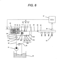
FIG. 6] FIG. 6 illustrates an exemplary fuel supply system using the high-pressure fuel supply pump according to a second embodiment of the present invention. - [
FIG. 7] FIG. 7 is a vertical cross-sectional view of the whole of the high-pressure fuel supply pump according to the second embodiment of the present invention. - [
FIG. 8] FIG. 8 is a vertical cross-sectional view of the whole of a high-pressure fuel supply pump according to a third embodiment of the present invention. - Hereinafter, an embodiment according to the present invention will be described.
- The configuration and operation of a system will be described with reference to the view of the whole configuration of the system illustrated in
FIG. 4 . - A part surrounded by a dashed line is the body of a high-pressure fuel supply pump (hereinafter, referred to as a high-pressure pump) . The mechanism and parts in the dashed line are integrally embedded in a high-
pressure pump body 1. The fuel in afuel tank 20 is pumped up by afeed pump 21, and fed via anintake pipe 28 to anintake joint 10a of thepump body 1. - After passing through the
intake joint 10a, the fuel passes through a pressurepulsation reducing mechanism 9, and anintake path 10b, and reaches anintake port 30a of anelectromagnetic inlet valve 30 included in a flow rate control mechanism. Thepulsation preventing mechanism 9 will be described below. - The
electromagnetic inlet valve 30 includes anelectromagnetic coil 308. When theelectromagnetic coil 308 does not conduct electricity, the difference between the biasing force of ananchor spring 303 and the biasing force of avalve spring 304 biases aninlet valve body 301 in a valve-opening direction in which theinlet valve body 301 is opened, and this opens the intake opening 30d. Note that the biasing force of theanchor spring 303 and the biasing force of thevalve spring 304 are set so that the biasing force of theanchor spring 303 > the biasing force of thevalve spring 304 holds. - When the
electromagnetic coil 308 conducts electricity, a state in which ananchor 305 is moved to the left side ofFIG. 4 and theanchor spring 303 is compressed is maintained. Aninlet valve body 301 with which the tip of anelectromagnetic plunger 305 coaxially has contact seals the intake opening 30d connected to a pressurizingchamber 11 of the high-pressure pump using the biasing force of thevalve spring 304. - The operation of the high-pressure pump will be described hereinafter.
- When the rotation of a cam described below displaces a
plunger 2 downward inFIG. 1 and theplunger 2 is in an intake process, the volume of the pressurizingchamber 11 is increased and the fuel pressure in the pressurizingchamber 11 is decreased. In the intake process, when the fuel pressure in the pressurizingchamber 11 is reduced to a pressure lower than the pressure in theintake path 10b (theintake port 30a), the fuel passes through the opened intake opening 30d and flows into the pressurizingchamber 11. When theplunger 2 completes the intake process and moves to a compression process, theplunger 2 moves to the compression process (a state in which theplunger 2 moves upward inFIG. 1 ) . At that time, a state in which theelectromagnetic coil 308 does not conduct electricity is maintained, and thus magnetic biasing force does not act. Thus, theinlet valve body 301 is still opened by the biasing force of theanchor spring 303. The volume of the pressurizingchamber 11 decreases with the compressing motion of theplunger 2 . In such a state, the fuel sucked in the pressurizingchamber 11 is returned through the openedinlet valve body 301 to theintake path 10b (theintake port 30a) . Thus, the pressure in the pressurizing chamber is not increased. This process is referred to as a return process. - When a control signal from an engine control unit 27 (hereinafter, referred to as ECU) is applied to the
electromagnetic inlet valve 30 in the return process, a current flows through theelectromagnetic coil 308 of theelectromagnetic inlet valve 30. The magnetic biasing force moves theelectromagnetic plunger 305 to the left side ofFIG. 4 and a state in which theanchor spring 303 is compressed is maintained. As a result, the biasing force of theanchor spring 303 does not act on theinlet valve body 301. The fluid force due to the biasing force of thevalve spring 304 and the flow of the fuel into theintake path 10b (theintake port 30a) acts. This closes theinlet valve 301 and thus closes theintake opening 30d. When theintake opening 30d is closed, the fuel pressure in the pressurizingchamber 11 starts increasing with the upward motion of theplunger 2. When the fuel pressure is larger than or equal to the pressure in the discharge joint 12, the fuel remaining in the pressurizingchamber 11 is discharged at high pressure through thedischarge valve mechanism 8, and fed to thecommon rail 23. This process is referred to as a discharge process. - In other words, the compression process of the plunger 2 (a process in which the
plunger 2 rises from a lower starting point to an upper starting point) includes the return process and the discharge process. Controlling the timing at which theelectromagnetic coil 308 of theelectromagnetic inlet valve 30 conducts electricity can control the amount of the high-pressure fuel to be discharged. When the timing at which theelectromagnetic coil 308 conducts electricity is hastened, the proportion of the return process is low and the proportion of the discharge process is high to the compression process. In other words, the amount of fuel to be returned to theintake path 10b (theintake port 30a) is decreased and the amount of fuel to be discharged at high pressure is increased. On the other hand, when the timing at which theelectromagnetic coil 308 conducts electricity is delayed, the proportion of the return process is high and the proportion of the discharge process is low to the compression process . In other words, the amount of fuel to be returned to theintake path 10b is increased and the amount of fuel to be discharged at high pressure is decreased. The timing at which theelectromagnetic coil 308 conducts electricity is controlled by the instructions from the ECU. - The configuration described above controls the timing at which the
electromagnetic coil 308 conducts electricity. This can control the amount of fuel to be discharged at high pressure in accordance with the amount of fuel that the internal-combustion engine requires. - The outlet of the pressurizing
chamber 11 is provided with adischarge valve mechanism 8. Thedischarge valve mechanism 8 includes adischarge valve seat 8a, adischarge valve 8b, and adischarge valve spring 8c. When there is no fuel differential pressure between the pressurizingchamber 11 and the discharge joint 12, thedischarge valve 8b is pressed and fixed to thedischarge valve seat 8a and closed by the biasing force of thedischarge valve spring 8c. When the fuel pressure in the pressurizingchamber 11 exceeds the fuel pressure in the discharge joint 12, thedischarge valve 8b is opened against thedischarge valve spring 8c and the fuel in the pressurizingchamber 11 is discharged at high pressure through the discharge joint 12 to thecommon rail 23. - As described above, the fuel guided to the intake joint 10a is pressurized at high pressure by the reciprocation of the
plunger 2 in the pressurizingchamber 11 of thepump body 1 as much as necessary, and fed from the discharge joint 12 to thecommon rail 23 by the pressure. -
Injectors 24 for direct injection (namely, a direct-injection injectors) and apressure sensor 26 are attached to thecommon rail 23. The number of the attached direct-injection injectors 24 corresponds to the number of cylinder engines of the internal-combustion engine. The direct-injection injectors 24 open and close in accordance with the control signal from the engine control unit (ECU) 27 so as to inject the fuel in the cylinder. - The
pump body 1 is further provided with adischarge flow path 110 communicating the downstream part of thedischarge valve 8b with the pressurizingchamber 11 and bypassing the discharge valve, separately from the discharge flow path. Thedischarge flow path 110 is provided with apressure relief valve 104 that limits the flow of the fuel only to a direction from the discharge flow path to the pressurizingchamber 11. Thepressure relief valve 104 is pressed to the pressurerelief valve seat 105 by therelief spring 102 that generates pressing force. When the difference between the pressure in the pressurizing chamber and the pressure in a relief path is larger than or equal to a predetermined pressure, thepressure relief valve 104 moves away from the pressurerelief valve seat 105 and opens. - For example, when a failure of the direct-
injection injector 24 causes an excessive high pressure in thecommon rail 23 and the differential pressure between thedischarge flow path 110 and the pressurizingchamber 11 is larger than or equal to the valve-opening pressure at which thepressure relief valve 104 is opened, thepressure relief valve 104 opens and the discharge flow path at the excessive high pressure is returned from thedischarge flow path 110 to the pressurizingchamber 11. This protects a high-pressure pipe such as thecommon rail 23. - Hereinafter, the configuration and operation of the high-pressure fuel pump will be described in more detail with reference to
FIGS. 1 to 4 . A general high-pressure pump is air-tightly sealed and fixed to the flat surface of acylinder head 41 of the internal-combustion engine with a flange 1e provided to thepump body 1. An O-ring 61 is fitted to thepump body 1 so that the airtightness between the cylinder head and the pump body is retained. - A
cylinder 6 is attached to thepump body 1. Thecylinder 6 is formed in a cylinder with a bottom on an end so that thecylinder 6 guides the back-and-forth movement of theplunger 2 and the pressurizingchamber 11 is formed in thecylinder 6. The pressurizingchamber 11 is provided with a plurality ofcommunication holes 11a so that the pressurizingchamber 11 communicates with theelectromagnetic inlet valve 30 configured to feed the fuel and thedischarge valve mechanism 8 configured to discharge the fuel from the pressurizingchamber 11 to the discharge path. - The outer diameter of the
cylinder 6 includes a large-diameter part and a small-diameter part. The small-diameter part is pressed and inserted in thepump body 1. The surface of awidth difference 6a between the large-diameter part and the small-diameter part is pressed and fixed to thepump body 1. This prevents the fuel pressurized in the pressurizingchamber 11 from leaking to the low-pressure side. - The lower end of the
plunger 2 is provided with atappet 3 that converts the rotation movement of acam 5 attached to a camshaft of the internal-combustion engine into up-and-down movement, and transmits the up-and-down movement to theplunger 2. Theplunger 2 is pressed and fixed to thetappet 3 through aretainer 15 with aspring 4. This can move (reciprocate) theplunger 2 up and down with the rotation movement of thecam 5. - A
plunger seal 13 held on the lower end of the inner periphery of theseal holder 7 has slidably contact with the outer periphery of theplunger 2 on the lower end of thecylinder 6 in the drawing. This seals the blow-by gap between theplunger 2 and thecylinder 6 and prevents the fuel from leaking to the outside of the pump. Meanwhile, this prevents the lubricant (including engine oil) that smoothly moves a sliding part of the internal-combustion engine from leaking through the blow-by gap into thepump body 1. - The fuel sucked by the
feed pump 21 is fed through the intake joint 10a coupled with theintake pipe 28 to thepump body 1. - A
damper cover 14 is coupled with thepump body 1 and forms a low-pressure fuel chamber 10. The fuel passing through the inlet joint 10a flows into the low-pressure fuel chamber 10. In order to remove an obstacle such as a metal powder in the fuel, afuel filter 102 is attached to the upstream part of the low-pressure fuel chamber 10, for example, while being pressed and inserted in thepump body 1. - A pressure
pulsation reducing mechanism 9 is installed in the low-pressure fuel chamber 10 so that the pressurepulsation reducing mechanism 9 reduces the spread of the pressure pulsation generated in the high-pressure pump to afuel pipe 28. When the fuel sucked in the pressurizingchamber 11 is returned through the openedinlet valve body 301 to theintake path 10b (theintake port 30a) under a state in which the flow rate of the fuel is controlled, the fuel returned to theintake path 10b (theintake port 30a) generates the pressure pulsation in the low-pressure fuel chamber 10. However, the pressure pulsation is absorbed and reduced by the expansion and contraction of ametal damper 9a forming the pressurepulsation reducing mechanism 9 provided to the low-pressure fuel chamber 10. Themetal damper 9a is formed of two corrugated metal disks of which outer peripheries are bonded together. Inert gas such as argon is injected in themetal damper 9a. Mountinghardware 9b is configured to fix themetal damper 9a on the inner periphery of thepump body 1. - The
electromagnetic inlet valve 30 is a variable control mechanism that includes theelectromagnetic coil 308. Theelectromagnetic inlet valve 30 is connected to the ECU through the terminal 307 and repeats conduction and non-conduction of electricity so as to open and close the inlet valve and control the flow rate of the fuel. - When the
electromagnetic coil 308 does not conduct electricity, the biasing force of theanchor spring 303 is transmitted to theinlet valve body 301 through theanchor 305 and theanchor rod 302 integrally formed with theanchor 305. The biasing force of thevalve spring 304 installed in the inlet valve body is set so that the biasing force of theanchor spring 303 > the biasing force of thevalve spring 304 holds. As a result, theinlet valve body 301 is biased in a valve-opening direction in which theinlet valve body 301 is opened. Theintake opening 30d is opened. Meanwhile, theanchor rod 302 has contact with theinlet valve body 301 at apart 302b (in a state illustratedFIG. 1 ). - The setting for the magnetic biasing force generated by the electricity conduction through the
coil 308 is configured to enable theanchor 305 to overcome the biasing force of theanchor spring 303 and be sucked into astator 306. When thecoil 308 conducts electricity, theanchor 303 moves toward the stator 306 (the left side of the drawing) and astopper 302a formed on an end of theanchor rod 302 has contact with an anchor rod bearing 309 and is seized. At that time, the clearance is set so that the travel distance of theanchor 301 > the travel distance of theinlet valve body 301 holds. Thecontact part 302b opens between theanchor rod 302 and theinlet valve body 301. As a result, theinlet valve body 301 is biased by thevalve spring 304 and theintake opening 30d is closed. - The
electromagnetic inlet valve 30 is fixed to thepump body 1 while aninlet valve seat 310 is hermetically inserted in atubular boss 1b so that theinlet valve body 301 can seal theintake opening 30d to the pressurizing chamber. When theelectromagnetic inlet valve 30 is attached to thepump body 1, theintake port 30a is connected to theintake path 10b. - The
discharge valve mechanism 8 is provided with a plurality of discharge paths radially drilled around the sliding axis of thedischarge valve body 8b. Thedischarge valve mechanism 8 includes a dischargevalve seat member 8a and adischarge valve member 8b. The dischargevalve seat member 8a is provided with a bearing that can sustain the sliding reciprocation of thedischarge valve body 8b at the center of the dischargevalve seat member 8a. Thedischarge valve member 8b has the central axis so as to slide with respect to the bearing of the dischargevalve seat member 8a, and has a circular contact surface on the outer periphery. The circular contact surface can retain the airtightness by having contact with the dischargevalve seat member 8a. Furthermore, adischarge valve spring 33 is inserted and held in thedischarge valve mechanism 8. Thedischarge valve spring 33 is a coil spring that biases thedischarge valve member 8b in a valve-closing direction in which thedischarge valve member 8b is closed. The discharge valve seat member, for example, is pressed, inserted and held in thepump body 1. Thedischarge valve member 8b and thedischarge valve spring 33 are further inserted in thepump body 1. A sealingplug 17 seals thepump body 1. This forms thedischarge valve mechanism 8. Thedischarge valve mechanism 8 is formed as described above. The formation causes thedischarge valve mechanism 8 to function as a check valve that controls the direction in which the fuel flows. - The operation of the pressure relief valve mechanism will be described in detail. As illustrated, a pressure
relief valve mechanism 100 includes a pressurerelief valve housing 101, arelief spring 102, arelief holder 103, apressure relief valve 104, and a pressurerelief valve seat 105. After the pressurerelief valve seat 105 is pressed, inserted and fixed to the pressurerelief valve housing 101, thepressure relief valve 104, therelief holder 103, and therelief spring 102 are sequentially inserted. The set load of therelief spring 102 is determined depending on the position at which the pressure relief valve seat is fixed. The valve-opening pressure at which thepressure relief valve 104 is opened is determined depending on the set load of therelief spring 102. The pressurerelief valve mechanism 100 unitized as described above is fixed to thepump body 1 by the press-insertion of the pressurerelief valve seat 105 to the inner peripheral wall of a cylindrical pass-through slot 1C provided to thepump body 1. Subsequently, the discharge joint 12 is fixed so that the discharge joint 12 blocks the cylindrical pass-through slot 1C of thepump body 1 so as to prevent the fuel from leaking from the high-pressure pump to the outside and to enable the pressurerelief valve mechanism 100 to be connected to a common rail. Meanwhile, the pressurerelief valve mechanism 100 is partially stored in the discharge joint 12. - The
discharge valve mechanism 8 and the pressurerelief valve mechanism 100 are installed in the pump body so that the central axes of thedischarge valve mechanism 8 and the pressurerelief valve mechanism 100 are radially arranged around the pressurizingchamber 11. This can make the process easy while thepump body 1 is produced. - The overshoot generated in the pressurizing chamber will be described with reference to
FIG. 5 . When the motion of theplunger 2 starts decreasing the volume of the pressurizingchamber 11, the pressure in the pressurizing chamber increases with the decrease in volume. When the pressure in the pressurizing chamber finally exceeds the pressure in thedischarge flow path 110, thedischarge valve mechanism 8 is opened and the fuel is discharged from the pressurizingchamber 11 to thedischarge flow path 110. From the moment thedischarge valve mechanism 8 is opened to the time immediately after the opening, the pressure in the pressurizing chamber overshoots and becomes very high. The very high pressure propagates in the discharge flow path and the pressure in the discharge flow path simultaneously overshoots. If the outlet of the pressurerelief valve mechanism 100 is connected to theintake flow pass 10b at the overshoot, the overshoot of the pressure in the discharge flow path causes the pressure difference between the inlet and outlet of thepressure relief valve 104 to exceed the valve-opining pressure at which the pressurerelief valve mechanism 100 is opened. This causes an error in the pressure relief valve. In light of the foregoing, the outlet of the pressurerelief valve mechanism 100 of the embodiment is connected to the pressurizingchamber 11, and thus the pressure in the pressurizing chamber acts on the outlet of the pressurerelief valve mechanism 100 and the pressure in thedischarge flow path 110 acts on the inlet of the pressurerelief valve mechanism 11. The pressure overshoot occurs simultaneously in the pressurizing chamber and the discharge flow path. Thus, the pressures difference between the inlet and outlet of the pressure relief valve does not exceed the valve-opining pressure at which the pressure relief valve is opened. In other words, an error in the pressure relief valve does not occur. - When the motion of the
plunger 2 starts increasing the volume of the pressurizingchamber 11, the pressure in the pressurizing chamber decreases with the increase in volume. When the pressure in the pressurizing chamber falls below the pressure in theintake path 10b (theintake port 30a), the fuel flows from theintake path 10b (theintake port 30a) into the pressurizingchamber 11. When the motion of theplunger 2 starts decreasing the volume of the pressurizingchamber 11 again, the fuel is pressurized at high pressure and discharged due to the mechanism described above. - Next, an example in which failure of the direct-
injection injector 24 generates an excessive high pressure in thecommon rail 23 will be described in detail. - In the event of failure of the direct-injection injector, in other words, when the injection function of the direct-injection injector stops and the direct-injection injector does not feed the fuel fed in the
common rail 23 into the combustion chamber of the internal-combustion engine, the fuel accumulates between thedischarge valve mechanism 8 and thecommon rail 23. This causes an excessive high pressure of the fuel. When the fuel pressure moderately increases to the excessive high pressure, thepressure sensor 26 provided to thecommon rail 23 detects the abnormal pressure. Then, theelectromagnetic inlet valve 30 that is a flow rate control mechanism provided in the intake path theintake path 10b (theintake port 30a) is controlled by feedback control. The feedback control operates as a safety function to decrease the amount of the fuel to be discharged. However, the feedback control with the pressure sensor is not effective in dealing with an instantaneous excessive high pressure. When theelectromagnetic inlet valve 30 is out of order and keeps the maximum flow rate in an operation state in which the fuel is not required so much, the pressure at which the fuel is discharged excessively increases. In such a case, the excessive high pressure is not dissolved because of the failure of the flow rate control mechanism even when thepressure sensor 26 of thecommon rail 23 detects the excessive high pressure. - When the excessive high pressure described above occurs, the pressure
relief valve mechanism 100 of the embodiment functions as a safety valve. - When the motion of the
plunger 2 starts increasing the volume of the pressurizingchamber 11, the pressure in the pressurizing chamber decreases with the increase in volume. When the pressure in the inlet of the pressurerelief valve mechanism 100, namely, in the discharge flow path is higher than or equal to the pressure in the outlet of the pressure relief valve, namely, in the pressurizingchamber 11 by the valve-opening pressure at which the pressurerelief valve mechanism 100 is opened, the pressurerelief valve mechanism 100 is opened and returns the fuel at an excessive high pressure in the common rail to the pressurizing chamber. This return prevents the fuel pressure from being higher than or equal to a predetermined pressure even when an excessive high pressure occurs. This prevention protects the high-pressure pipe system including thecommon rail 23. - In the present embodiment, the mechanism described above prevents the pressure difference between the inlet and outlet of the pressure
relief valve mechanism 100 from being higher than or equal to the valve-opening pressure at which the pressurerelief valve mechanism 100 is opened, and thus, the pressurerelief valve mechanism 100 is not opened in the discharge process. - In the intake process and the return process, the fuel pressure in the pressurizing
chamber 11 decreases to a low pressure identical to the pressure in theintake pipe 28. On the other hand, the pressure in therelief chamber 112 increases to a pressure identical to the pressure in thecommon rail 23. When the differential pressure between therelief chamber 112 and the pressurizing chamber is higher than or equal to the valve-opening pressure at which thepressure relief valve 104 is opened, thepressure relief valve 104 is opened and the fuel at an excessive high pressure is returned from therelief chamber 112 to the pressurizingchamber 11. This protects the high-pressure pipe system including thecommon rail 23. - Next, a second embodiment will be described with reference to
FIGS. 6 and7 . - In the second embodiment, a pressure
relief valve mechanism 100 provided to apump body 1 communicates the downstream part of adischarge valve 8b with anintake path 10b. Apressure relief valve 104 is pressed to a pressurerelief valve seat 105 by arelief spring 102 generating pressing force. When the pressure difference between the intake path and a relief path is higher than or equal to a predetermined pressure, thepressure relief valve 104 moves away from the pressurerelief valve seat 105 and opens. - When, for example, failure of a direct-
injection injector 24 generates an excessive high pressure, for example, in acommon rail 23 and the differential pressure between thedischarge flow path 110 and theintake path 10b is higher than or equal to the valve-opening pressure at which thepressure relief valve 104 is opened, thepressure relief valve 104 is opened and the discharge flow path at the excessive high pressure is returned from thedischarge flow path 110 to the pressurizingchamber 11. This protects the high-pressure pipe system including thecommon rail 23. - Next, a third embodiment will be described with reference to
FIGS. 8 and 9. - In the third embodiment, a pressure
relief valve mechanism 100 includes a pressurerelief valve stopper 101, apressure relief valve 102, a pressurerelief valve seat 103, arelief spring stopper 104, and arelief spring 105 as illustrated. The pressurerelief valve seat 103 includes a bearing that enables thepressure relief valve 102 to slide. Thepressure relief valve 102 integrally including a sliding shaft is inserted in the pressurerelief valve seat 103. After that the position of therelief spring stopper 104 is determined so that therelief spring 105 has a desired load, and therelief spring stopper 104 is fixed to thepressure relief valve 102, for example, by press and insertion. The valve-opening pressure at which thepressure relief valve 102 is opened is determined depending on the pressing force of therelief spring 105. The pressurerelief valve stopper 101 is inserted between thepump body 1 and the pressurerelief valve seat 103 so as to function as a stopper that controls how much thepressure relief valve 102 is opened. The pressurerelief valve mechanism 100 unitized as described above is fixed to thepump body 1 by the press and insertion of the pressurerelief valve seat 103 to the inner peripheral wall of a cylindrical pass-through slot 1C provided to thepump body 1. In other words, the pressure relief valve is an inward-opening valve. Therelief spring 105 is provided on a side of thepressure relief valve 102 facing the discharge joint 12 as described above. This prevents the increase in volume of the pressurizingchamber 11 even when the outlet of thepressure relief valve 104 of the pressurerelief valve mechanism 100 is opened toward the pressurizingchamber 11. - According to a first aspect
a high-pressure fuel pump comprises: - two first and second valve chests formed in a pump body;
- a discharge valve placed in the first valve chest;
- a pressure relief valve placed in the second valve chest;
- springs that bias the discharge valve and the pressure relief valve toward valve seats, respectively; and
- a discharge joint that partially stores the pressure relief valve mechanism and is connected to a high-pressure pipe.
- The high-pressure pump according to the first aspect, further comprises:
a plug that seals the valve mechanism attachment hole in which the discharge valve and the spring biasing the discharge valve are stored. - The high-pressure pump according to the second aspect, further comprises:
a discharge path formed in a pump housing, the discharge path being configured to connect a high-pressure path of a downstream part of the discharge valve to a downstream part of the pressure relief valve. - In the high-pressure pump according to the first aspect, a central axis of the discharge valve and a central axis of the pressure relief valve are radially arranged around a pressurizing chamber.
- In the high-pressure pump according to the first aspect, the pressure relief valve is an inward-opening valve.
-
- 1
- pump body
- 2
- plunger
- 6
- cylinder
- 8
- discharge valve mechanism
- 9
- pressure pulsation reducing mechanism
- 11
- pressurizing chamber
- 30
- electromagnetic inlet valve
- 100
- pressure relief valve mechanism
- 101
- pressure relief valve housing
- 102
- relief spring
- 103
- relief holder
- 104
- pressure relief valve
- 105
- pressure relief valve seat
Claims (6)
- A high-pressure fuel pump comprising:- a pump body (1) including a pressurizing chamber (11);- a discharge valve (8b) of a discharge valve mechanism (8) provided in a first path communicating with the pressurizing chamber (11);- a discharge joint (12) discharging a fuel pressurized in the pressurizing chamber (11); and- a pressure relief spring (102) of a pressure relief valve mechanism (100) at least partially stored in the discharge joint (12),characterized in that:
the pump body (1) includes a second path (110) adapted to communicatively couple a downstream part of the discharge valve (8b) with the pressurizing chamber (11), wherein the pressure relief valve mechanism (100) is provided in the second path (110). - The high-pressure pump according to claim 1, wherein
the discharge joint (12) is adapted to partially store the pressure relief valve mechanism (100). - The high-pressure pump according to claim 1 or 2, wherein
the pressure relief valve mechanism (100) and the discharge valve mechanism (8) are placed on same cross horizontal section of the pump body (1). - The high-pressure pump according to claim 1 or 2, wherein
the pressure relief valve mechanism (100), the discharge valve mechanism (8) and a cylinder (6) guiding a movement of a plunger (2) in the pressurizing chamber (11) are placed on same horizontal cross section of the pump body (1). - The high-pressure pump according to any one of claims 1 to 4, wherein
the relief valve mechanism (100) includes a pressure relief valve housing (101), the pressure relief spring (102), a relief holder (103), a pressure relief valve (104) and a pressure relief valve seat (105), and is fixed to the pump body (1). - The high-pressure pump according to any one of claims 1 to 5, wherein
the discharge valve mechanism (8) includes a discharge valve seat (8a), the discharge valve (8b) and a discharge valve spring (8c), and a sealing plug (17) seals an opening of the pump body (1) provided with the discharge valve mechanism (8).
Applications Claiming Priority (3)
| Application Number | Priority Date | Filing Date | Title |
|---|---|---|---|
| JP2014090822 | 2014-04-25 | ||
| PCT/JP2015/061776 WO2015163245A1 (en) | 2014-04-25 | 2015-04-17 | High-pressure fuel supply pump |
| EP15783842.6A EP3135901B1 (en) | 2014-04-25 | 2015-04-17 | High-pressure fuel supply pump |
Related Parent Applications (1)
| Application Number | Title | Priority Date | Filing Date |
|---|---|---|---|
| EP15783842.6A Division EP3135901B1 (en) | 2014-04-25 | 2015-04-17 | High-pressure fuel supply pump |
Publications (2)
| Publication Number | Publication Date |
|---|---|
| EP3587790A1 EP3587790A1 (en) | 2020-01-01 |
| EP3587790B1 true EP3587790B1 (en) | 2023-03-08 |
Family
ID=54332411
Family Applications (2)
| Application Number | Title | Priority Date | Filing Date |
|---|---|---|---|
| EP19186498.2A Active EP3587790B1 (en) | 2014-04-25 | 2015-04-17 | High-pressure fuel supply pump |
| EP15783842.6A Active EP3135901B1 (en) | 2014-04-25 | 2015-04-17 | High-pressure fuel supply pump |
Family Applications After (1)
| Application Number | Title | Priority Date | Filing Date |
|---|---|---|---|
| EP15783842.6A Active EP3135901B1 (en) | 2014-04-25 | 2015-04-17 | High-pressure fuel supply pump |
Country Status (5)
| Country | Link |
|---|---|
| US (1) | US10941741B2 (en) |
| EP (2) | EP3587790B1 (en) |
| JP (2) | JP6470267B2 (en) |
| CN (2) | CN111322187B (en) |
| WO (1) | WO2015163245A1 (en) |
Families Citing this family (8)
| Publication number | Priority date | Publication date | Assignee | Title |
|---|---|---|---|---|
| US10788003B2 (en) * | 2016-04-06 | 2020-09-29 | Hitachi Automotive Systems, Ltd. | High-pressure fuel supply pump |
| JP6569589B2 (en) * | 2016-04-28 | 2019-09-04 | 株式会社デンソー | High pressure pump |
| US20190301414A1 (en) * | 2016-05-27 | 2019-10-03 | Hitachi Automotive Systems, Ltd. | High-Pressure Fuel Supply Pump |
| CN109937297A (en) * | 2016-11-18 | 2019-06-25 | 日立汽车系统株式会社 | High-pressure fuel feed pump |
| JP6897173B2 (en) * | 2017-03-07 | 2021-06-30 | 株式会社デンソー | High pressure pump |
| JP6809520B2 (en) * | 2017-09-29 | 2021-01-06 | 株式会社デンソー | High pressure pump |
| JP7397729B2 (en) | 2020-03-18 | 2023-12-13 | 日立Astemo株式会社 | Fuel pump |
| CN112648120A (en) * | 2020-12-23 | 2021-04-13 | 南岳电控(衡阳)工业技术股份有限公司 | Single-cylinder common-rail oil supply pump of blade-mounted oil transfer pump |
Family Cites Families (39)
| Publication number | Priority date | Publication date | Assignee | Title |
|---|---|---|---|---|
| DE7925377U1 (en) * | 1979-09-07 | 1979-12-06 | Robert Bosch Gmbh, 7000 Stuttgart | FUEL INJECTION PUMP FOR COMBUSTION MACHINES |
| JPS5641157U (en) * | 1979-09-07 | 1981-04-16 | ||
| IT1150318B (en) * | 1981-03-21 | 1986-12-10 | Bosch Gmbh Robert | FUEL INJECTION PUMP FOR ENDOTHERMAL ENGINES |
| DE3141654A1 (en) * | 1981-10-21 | 1983-05-05 | L'Orange GmbH, 7000 Stuttgart | FUEL INJECTION PUMP, ESPECIALLY FOR A DIESEL INTERNAL COMBUSTION ENGINE |
| DE3218960A1 (en) * | 1982-05-19 | 1983-11-24 | Speck Kolbenpumpen Fabrik | PUMP, IN PARTICULAR HIGH PRESSURE PUMP FOR CONVEYING LIQUIDS |
| JPH0341089Y2 (en) * | 1987-04-18 | 1991-08-29 | ||
| JPH116475A (en) * | 1997-06-18 | 1999-01-12 | Unisia Jecs Corp | Pump for fuel pressurization |
| DE10327411B4 (en) * | 2002-10-15 | 2015-12-17 | Robert Bosch Gmbh | Pressure relief valve and fuel system with such a pressure relief valve |
| JP2004218547A (en) | 2003-01-15 | 2004-08-05 | Bosch Automotive Systems Corp | High pressure fuel pump |
| JP4415884B2 (en) * | 2005-03-11 | 2010-02-17 | 株式会社日立製作所 | Electromagnetic drive mechanism, high pressure fuel supply pump with electromagnetic valve mechanism and intake valve operated by electromagnetic drive mechanism, high pressure fuel supply pump with electromagnetic valve mechanism |
| JP2007120492A (en) * | 2005-09-29 | 2007-05-17 | Denso Corp | High pressure fuel pump |
| JP4415929B2 (en) * | 2005-11-16 | 2010-02-17 | 株式会社日立製作所 | High pressure fuel supply pump |
| JP4437552B2 (en) * | 2006-05-26 | 2010-03-24 | 株式会社デンソー | High pressure fuel pump |
| JP2008057451A (en) * | 2006-08-31 | 2008-03-13 | Hitachi Ltd | High-pressure fuel supply pump |
| JP2008064013A (en) * | 2006-09-07 | 2008-03-21 | Hitachi Ltd | High pressure fuel supply pump |
| JP4353288B2 (en) * | 2007-08-08 | 2009-10-28 | トヨタ自動車株式会社 | Fuel pump |
| JP4413260B2 (en) | 2007-10-12 | 2010-02-10 | 株式会社日本自動車部品総合研究所 | High pressure fuel pump |
| JP2009103008A (en) | 2007-10-22 | 2009-05-14 | Toyota Motor Corp | Fuel pump |
| JP4945504B2 (en) * | 2008-04-17 | 2012-06-06 | 日立オートモティブシステムズ株式会社 | High pressure fuel supply pump |
| JP5002523B2 (en) * | 2008-04-25 | 2012-08-15 | 日立オートモティブシステムズ株式会社 | Fuel pressure pulsation reduction mechanism and high-pressure fuel supply pump for internal combustion engine equipped with the same |
| JP5252314B2 (en) | 2008-12-26 | 2013-07-31 | 株式会社デンソー | High pressure pump |
| IT1396473B1 (en) * | 2009-03-30 | 2012-12-14 | Magneti Marelli Spa | FUEL PUMP WITH A MAXIMUM PRESSURE VALVE PERFECTED FOR A DIRECT INJECTION SYSTEM |
| JP5493966B2 (en) * | 2009-06-02 | 2014-05-14 | 株式会社デンソー | Fuel injection device |
| IT1396142B1 (en) * | 2009-11-03 | 2012-11-16 | Magneti Marelli Spa | FUEL PUMP WITH DAMPENER PERFECTED FOR A DIRECT INJECTION SYSTEM |
| KR101526375B1 (en) * | 2009-11-11 | 2015-06-08 | 현대자동차 주식회사 | High pressure fuel pump integrally provided with discharge valve and pressure relief valve |
| US8132558B2 (en) * | 2009-12-01 | 2012-03-13 | Stanadyne Corporation | Common rail fuel pump with combined discharge and overpressure relief valves |
| DE102010001880A1 (en) * | 2010-02-12 | 2011-08-18 | Robert Bosch GmbH, 70469 | Cylinder head for a high-pressure fuel pump |
| JP5226712B2 (en) * | 2010-02-26 | 2013-07-03 | ヤンマー株式会社 | Fuel injection pump |
| JP5401360B2 (en) * | 2010-02-26 | 2014-01-29 | 日立オートモティブシステムズ株式会社 | High pressure fuel supply pump |
| KR101182131B1 (en) | 2010-08-23 | 2012-09-12 | (주)모토닉 | High presure fuel pump for direct injection type gasoline engine |
| JP5501272B2 (en) * | 2011-03-08 | 2014-05-21 | 日立オートモティブシステムズ株式会社 | High pressure fuel supply pump |
| JP5472751B2 (en) * | 2011-03-30 | 2014-04-16 | 株式会社デンソー | High pressure pump |
| US9181944B2 (en) | 2011-03-31 | 2015-11-10 | Denso Corporation | High pressure pump having unitary discharge and relief valve |
| JP5653288B2 (en) * | 2011-04-27 | 2015-01-14 | 株式会社デンソー | Constant residual pressure valve |
| JP5639970B2 (en) * | 2011-08-03 | 2014-12-10 | 日立オートモティブシステムズ株式会社 | Control method for electromagnetic valve, control method for electromagnetic suction valve of high-pressure fuel supply pump, and control device for electromagnetic drive mechanism of electromagnetic suction valve |
| ES2865184T3 (en) * | 2011-11-17 | 2021-10-15 | Stanadyne Llc | Auxiliary pressure relief valve on single piston fuel pump |
| US10294906B2 (en) * | 2013-03-05 | 2019-05-21 | Stanadyne Llc | Electronically controlled inlet metered single piston fuel pump |
| JP2014224523A (en) * | 2013-04-18 | 2014-12-04 | 株式会社デンソー | Valve device and high-pressure pump using this valve device |
| JP5589121B2 (en) | 2013-06-06 | 2014-09-10 | 日立オートモティブシステムズ株式会社 | High pressure fuel supply pump |
-
2015
- 2015-04-17 EP EP19186498.2A patent/EP3587790B1/en active Active
- 2015-04-17 WO PCT/JP2015/061776 patent/WO2015163245A1/en active Application Filing
- 2015-04-17 CN CN202010084729.7A patent/CN111322187B/en active Active
- 2015-04-17 JP JP2016514898A patent/JP6470267B2/en active Active
- 2015-04-17 US US15/304,237 patent/US10941741B2/en active Active
- 2015-04-17 EP EP15783842.6A patent/EP3135901B1/en active Active
- 2015-04-17 CN CN201580021052.XA patent/CN106232978B/en active Active
-
2019
- 2019-01-17 JP JP2019005751A patent/JP6860598B2/en active Active
Also Published As
| Publication number | Publication date |
|---|---|
| WO2015163245A1 (en) | 2015-10-29 |
| CN106232978B (en) | 2020-02-28 |
| CN111322187B (en) | 2021-12-31 |
| JP6470267B2 (en) | 2019-02-13 |
| EP3587790A1 (en) | 2020-01-01 |
| CN106232978A (en) | 2016-12-14 |
| EP3135901B1 (en) | 2019-07-31 |
| JP6860598B2 (en) | 2021-04-14 |
| US20170037822A1 (en) | 2017-02-09 |
| JP2019074092A (en) | 2019-05-16 |
| US10941741B2 (en) | 2021-03-09 |
| CN111322187A (en) | 2020-06-23 |
| EP3135901A4 (en) | 2018-01-03 |
| JPWO2015163245A1 (en) | 2017-04-13 |
| EP3135901A1 (en) | 2017-03-01 |
Similar Documents
| Publication | Publication Date | Title |
|---|---|---|
| EP3587790B1 (en) | High-pressure fuel supply pump | |
| EP3444469B1 (en) | Mechanism for restraining fuel pressure pulsation and high pressure fuel supply pump of internal combustion engine with such mechanism | |
| EP2497939B1 (en) | High-pressure fuel supply pump | |
| JP2007138762A (en) | High-pressure fuel supply pump | |
| EP3135900B1 (en) | High-pressure fuel supply pump | |
| EP3135969B1 (en) | Electromagnetic valve | |
| JP5589121B2 (en) | High pressure fuel supply pump | |
| CN110832188B (en) | High-pressure fuel pump | |
| EP3135899B1 (en) | High-pressure fuel pump | |
| WO2018012211A1 (en) | High-pressure fuel supply pump | |
| JP6483196B2 (en) | High pressure fuel supply pump | |
| US20220316470A1 (en) | Fuel Pump | |
| JP2018105274A (en) | High-pressure fuel supply pump | |
| JP6165674B2 (en) | High pressure fuel supply pump | |
| EP4191049A1 (en) | Fuel pump | |
| EP4286680A1 (en) | Electromagnetic valve mechanism and fuel pump | |
| EP4286718A1 (en) | Fuel pump | |
| EP4184001A1 (en) | Fuel pump | |
| JP7397729B2 (en) | Fuel pump | |
| JP2023030297A (en) | Fuel pump | |
| JP2017072027A (en) | High pressure fuel supply pump |
Legal Events
| Date | Code | Title | Description |
|---|---|---|---|
| PUAI | Public reference made under article 153(3) epc to a published international application that has entered the european phase |
Free format text: ORIGINAL CODE: 0009012 |
|
| STAA | Information on the status of an ep patent application or granted ep patent |
Free format text: STATUS: REQUEST FOR EXAMINATION WAS MADE |
|
| 17P | Request for examination filed |
Effective date: 20190909 |
|
| AC | Divisional application: reference to earlier application |
Ref document number: 3135901 Country of ref document: EP Kind code of ref document: P |
|
| AK | Designated contracting states |
Kind code of ref document: A1 Designated state(s): AL AT BE BG CH CY CZ DE DK EE ES FI FR GB GR HR HU IE IS IT LI LT LU LV MC MK MT NL NO PL PT RO RS SE SI SK SM TR |
|
| STAA | Information on the status of an ep patent application or granted ep patent |
Free format text: STATUS: EXAMINATION IS IN PROGRESS |
|
| 17Q | First examination report despatched |
Effective date: 20210312 |
|
| RAP3 | Party data changed (applicant data changed or rights of an application transferred) |
Owner name: HITACHI ASTEMO, LTD. |
|
| GRAP | Despatch of communication of intention to grant a patent |
Free format text: ORIGINAL CODE: EPIDOSNIGR1 |
|
| STAA | Information on the status of an ep patent application or granted ep patent |
Free format text: STATUS: GRANT OF PATENT IS INTENDED |
|
| INTG | Intention to grant announced |
Effective date: 20221017 |
|
| GRAS | Grant fee paid |
Free format text: ORIGINAL CODE: EPIDOSNIGR3 |
|
| GRAA | (expected) grant |
Free format text: ORIGINAL CODE: 0009210 |
|
| STAA | Information on the status of an ep patent application or granted ep patent |
Free format text: STATUS: THE PATENT HAS BEEN GRANTED |
|
| AC | Divisional application: reference to earlier application |
Ref document number: 3135901 Country of ref document: EP Kind code of ref document: P |
|
| AK | Designated contracting states |
Kind code of ref document: B1 Designated state(s): AL AT BE BG CH CY CZ DE DK EE ES FI FR GB GR HR HU IE IS IT LI LT LU LV MC MK MT NL NO PL PT RO RS SE SI SK SM TR |
|
| REG | Reference to a national code |
Ref country code: CH Ref legal event code: EP Ref country code: AT Ref legal event code: REF Ref document number: 1552718 Country of ref document: AT Kind code of ref document: T Effective date: 20230315 |
|
| REG | Reference to a national code |
Ref country code: DE Ref legal event code: R096 Ref document number: 602015082782 Country of ref document: DE |
|
| REG | Reference to a national code |
Ref country code: IE Ref legal event code: FG4D |
|
| REG | Reference to a national code |
Ref country code: LT Ref legal event code: MG9D |
|
| REG | Reference to a national code |
Ref country code: NL Ref legal event code: MP Effective date: 20230308 |
|
| PG25 | Lapsed in a contracting state [announced via postgrant information from national office to epo] |
Ref country code: RS Free format text: LAPSE BECAUSE OF FAILURE TO SUBMIT A TRANSLATION OF THE DESCRIPTION OR TO PAY THE FEE WITHIN THE PRESCRIBED TIME-LIMIT Effective date: 20230308 Ref country code: NO Free format text: LAPSE BECAUSE OF FAILURE TO SUBMIT A TRANSLATION OF THE DESCRIPTION OR TO PAY THE FEE WITHIN THE PRESCRIBED TIME-LIMIT Effective date: 20230608 Ref country code: LV Free format text: LAPSE BECAUSE OF FAILURE TO SUBMIT A TRANSLATION OF THE DESCRIPTION OR TO PAY THE FEE WITHIN THE PRESCRIBED TIME-LIMIT Effective date: 20230308 Ref country code: LT Free format text: LAPSE BECAUSE OF FAILURE TO SUBMIT A TRANSLATION OF THE DESCRIPTION OR TO PAY THE FEE WITHIN THE PRESCRIBED TIME-LIMIT Effective date: 20230308 Ref country code: HR Free format text: LAPSE BECAUSE OF FAILURE TO SUBMIT A TRANSLATION OF THE DESCRIPTION OR TO PAY THE FEE WITHIN THE PRESCRIBED TIME-LIMIT Effective date: 20230308 Ref country code: ES Free format text: LAPSE BECAUSE OF FAILURE TO SUBMIT A TRANSLATION OF THE DESCRIPTION OR TO PAY THE FEE WITHIN THE PRESCRIBED TIME-LIMIT Effective date: 20230308 |
|
| PGFP | Annual fee paid to national office [announced via postgrant information from national office to epo] |
Ref country code: DE Payment date: 20230430 Year of fee payment: 9 |
|
| REG | Reference to a national code |
Ref country code: AT Ref legal event code: MK05 Ref document number: 1552718 Country of ref document: AT Kind code of ref document: T Effective date: 20230308 |
|
| PG25 | Lapsed in a contracting state [announced via postgrant information from national office to epo] |
Ref country code: SE Free format text: LAPSE BECAUSE OF FAILURE TO SUBMIT A TRANSLATION OF THE DESCRIPTION OR TO PAY THE FEE WITHIN THE PRESCRIBED TIME-LIMIT Effective date: 20230308 Ref country code: NL Free format text: LAPSE BECAUSE OF FAILURE TO SUBMIT A TRANSLATION OF THE DESCRIPTION OR TO PAY THE FEE WITHIN THE PRESCRIBED TIME-LIMIT Effective date: 20230308 Ref country code: GR Free format text: LAPSE BECAUSE OF FAILURE TO SUBMIT A TRANSLATION OF THE DESCRIPTION OR TO PAY THE FEE WITHIN THE PRESCRIBED TIME-LIMIT Effective date: 20230609 Ref country code: FI Free format text: LAPSE BECAUSE OF FAILURE TO SUBMIT A TRANSLATION OF THE DESCRIPTION OR TO PAY THE FEE WITHIN THE PRESCRIBED TIME-LIMIT Effective date: 20230308 |
|
| PG25 | Lapsed in a contracting state [announced via postgrant information from national office to epo] |
Ref country code: SM Free format text: LAPSE BECAUSE OF FAILURE TO SUBMIT A TRANSLATION OF THE DESCRIPTION OR TO PAY THE FEE WITHIN THE PRESCRIBED TIME-LIMIT Effective date: 20230308 Ref country code: RO Free format text: LAPSE BECAUSE OF FAILURE TO SUBMIT A TRANSLATION OF THE DESCRIPTION OR TO PAY THE FEE WITHIN THE PRESCRIBED TIME-LIMIT Effective date: 20230308 Ref country code: PT Free format text: LAPSE BECAUSE OF FAILURE TO SUBMIT A TRANSLATION OF THE DESCRIPTION OR TO PAY THE FEE WITHIN THE PRESCRIBED TIME-LIMIT Effective date: 20230710 Ref country code: EE Free format text: LAPSE BECAUSE OF FAILURE TO SUBMIT A TRANSLATION OF THE DESCRIPTION OR TO PAY THE FEE WITHIN THE PRESCRIBED TIME-LIMIT Effective date: 20230308 Ref country code: CZ Free format text: LAPSE BECAUSE OF FAILURE TO SUBMIT A TRANSLATION OF THE DESCRIPTION OR TO PAY THE FEE WITHIN THE PRESCRIBED TIME-LIMIT Effective date: 20230308 Ref country code: AT Free format text: LAPSE BECAUSE OF FAILURE TO SUBMIT A TRANSLATION OF THE DESCRIPTION OR TO PAY THE FEE WITHIN THE PRESCRIBED TIME-LIMIT Effective date: 20230308 |
|
| PG25 | Lapsed in a contracting state [announced via postgrant information from national office to epo] |
Ref country code: SK Free format text: LAPSE BECAUSE OF FAILURE TO SUBMIT A TRANSLATION OF THE DESCRIPTION OR TO PAY THE FEE WITHIN THE PRESCRIBED TIME-LIMIT Effective date: 20230308 Ref country code: PL Free format text: LAPSE BECAUSE OF FAILURE TO SUBMIT A TRANSLATION OF THE DESCRIPTION OR TO PAY THE FEE WITHIN THE PRESCRIBED TIME-LIMIT Effective date: 20230308 Ref country code: IS Free format text: LAPSE BECAUSE OF FAILURE TO SUBMIT A TRANSLATION OF THE DESCRIPTION OR TO PAY THE FEE WITHIN THE PRESCRIBED TIME-LIMIT Effective date: 20230708 |
|
| REG | Reference to a national code |
Ref country code: CH Ref legal event code: PL |
|
| REG | Reference to a national code |
Ref country code: DE Ref legal event code: R097 Ref document number: 602015082782 Country of ref document: DE |
|
| PG25 | Lapsed in a contracting state [announced via postgrant information from national office to epo] |
Ref country code: LU Free format text: LAPSE BECAUSE OF NON-PAYMENT OF DUE FEES Effective date: 20230417 |
|
| REG | Reference to a national code |
Ref country code: BE Ref legal event code: MM Effective date: 20230430 |
|
| PLBE | No opposition filed within time limit |
Free format text: ORIGINAL CODE: 0009261 |
|
| STAA | Information on the status of an ep patent application or granted ep patent |
Free format text: STATUS: NO OPPOSITION FILED WITHIN TIME LIMIT |
|
| PG25 | Lapsed in a contracting state [announced via postgrant information from national office to epo] |
Ref country code: MC Free format text: LAPSE BECAUSE OF FAILURE TO SUBMIT A TRANSLATION OF THE DESCRIPTION OR TO PAY THE FEE WITHIN THE PRESCRIBED TIME-LIMIT Effective date: 20230308 |
|
| PG25 | Lapsed in a contracting state [announced via postgrant information from national office to epo] |
Ref country code: SI Free format text: LAPSE BECAUSE OF FAILURE TO SUBMIT A TRANSLATION OF THE DESCRIPTION OR TO PAY THE FEE WITHIN THE PRESCRIBED TIME-LIMIT Effective date: 20230308 Ref country code: MC Free format text: LAPSE BECAUSE OF FAILURE TO SUBMIT A TRANSLATION OF THE DESCRIPTION OR TO PAY THE FEE WITHIN THE PRESCRIBED TIME-LIMIT Effective date: 20230308 Ref country code: LI Free format text: LAPSE BECAUSE OF NON-PAYMENT OF DUE FEES Effective date: 20230430 Ref country code: DK Free format text: LAPSE BECAUSE OF FAILURE TO SUBMIT A TRANSLATION OF THE DESCRIPTION OR TO PAY THE FEE WITHIN THE PRESCRIBED TIME-LIMIT Effective date: 20230308 Ref country code: CH Free format text: LAPSE BECAUSE OF NON-PAYMENT OF DUE FEES Effective date: 20230430 |
|
| 26N | No opposition filed |
Effective date: 20231211 |
|
| REG | Reference to a national code |
Ref country code: IE Ref legal event code: MM4A |
|
| GBPC | Gb: european patent ceased through non-payment of renewal fee |
Effective date: 20230608 |
|
| PG25 | Lapsed in a contracting state [announced via postgrant information from national office to epo] |
Ref country code: BE Free format text: LAPSE BECAUSE OF NON-PAYMENT OF DUE FEES Effective date: 20230430 |
|
| PG25 | Lapsed in a contracting state [announced via postgrant information from national office to epo] |
Ref country code: IE Free format text: LAPSE BECAUSE OF NON-PAYMENT OF DUE FEES Effective date: 20230417 |