EP3444469B1 - Mechanism for restraining fuel pressure pulsation and high pressure fuel supply pump of internal combustion engine with such mechanism - Google Patents
Mechanism for restraining fuel pressure pulsation and high pressure fuel supply pump of internal combustion engine with such mechanism Download PDFInfo
- Publication number
- EP3444469B1 EP3444469B1 EP18191492.0A EP18191492A EP3444469B1 EP 3444469 B1 EP3444469 B1 EP 3444469B1 EP 18191492 A EP18191492 A EP 18191492A EP 3444469 B1 EP3444469 B1 EP 3444469B1
- Authority
- EP
- European Patent Office
- Prior art keywords
- damper
- holding member
- pump housing
- fuel
- high pressure
- Prior art date
- Legal status (The legal status is an assumption and is not a legal conclusion. Google has not performed a legal analysis and makes no representation as to the accuracy of the status listed.)
- Active
Links
- 239000000446 fuel Substances 0.000 title claims description 180
- 230000007246 mechanism Effects 0.000 title claims description 51
- 230000010349 pulsation Effects 0.000 title description 36
- 238000002485 combustion reaction Methods 0.000 title description 4
- 230000000452 restraining effect Effects 0.000 title 1
- 239000002184 metal Substances 0.000 claims description 59
- 238000000034 method Methods 0.000 claims description 39
- 238000003466 welding Methods 0.000 claims description 10
- 230000001174 ascending effect Effects 0.000 claims description 6
- 238000003825 pressing Methods 0.000 claims description 4
- 229910000831 Steel Inorganic materials 0.000 claims description 2
- 238000004519 manufacturing process Methods 0.000 claims description 2
- 239000010959 steel Substances 0.000 claims description 2
- 230000008569 process Effects 0.000 description 34
- 230000007423 decrease Effects 0.000 description 10
- 230000002093 peripheral effect Effects 0.000 description 9
- 238000010586 diagram Methods 0.000 description 6
- 238000007906 compression Methods 0.000 description 5
- 239000012530 fluid Substances 0.000 description 4
- 230000000630 rising effect Effects 0.000 description 3
- 230000008859 change Effects 0.000 description 2
- 238000006073 displacement reaction Methods 0.000 description 2
- 239000002828 fuel tank Substances 0.000 description 2
- 238000002347 injection Methods 0.000 description 2
- 239000007924 injection Substances 0.000 description 2
- 230000002159 abnormal effect Effects 0.000 description 1
- 230000015572 biosynthetic process Effects 0.000 description 1
- 230000006835 compression Effects 0.000 description 1
- 238000007599 discharging Methods 0.000 description 1
- 238000005304 joining Methods 0.000 description 1
- 239000000314 lubricant Substances 0.000 description 1
- 239000010705 motor oil Substances 0.000 description 1
- 239000003921 oil Substances 0.000 description 1
- 238000007789 sealing Methods 0.000 description 1
- 238000011144 upstream manufacturing Methods 0.000 description 1
Images


Classifications
-
- F—MECHANICAL ENGINEERING; LIGHTING; HEATING; WEAPONS; BLASTING
- F04—POSITIVE - DISPLACEMENT MACHINES FOR LIQUIDS; PUMPS FOR LIQUIDS OR ELASTIC FLUIDS
- F04B—POSITIVE-DISPLACEMENT MACHINES FOR LIQUIDS; PUMPS
- F04B53/00—Component parts, details or accessories not provided for in, or of interest apart from, groups F04B1/00 - F04B23/00 or F04B39/00 - F04B47/00
- F04B53/16—Casings; Cylinders; Cylinder liners or heads; Fluid connections
-
- F—MECHANICAL ENGINEERING; LIGHTING; HEATING; WEAPONS; BLASTING
- F02—COMBUSTION ENGINES; HOT-GAS OR COMBUSTION-PRODUCT ENGINE PLANTS
- F02M—SUPPLYING COMBUSTION ENGINES IN GENERAL WITH COMBUSTIBLE MIXTURES OR CONSTITUENTS THEREOF
- F02M37/00—Apparatus or systems for feeding liquid fuel from storage containers to carburettors or fuel-injection apparatus; Arrangements for purifying liquid fuel specially adapted for, or arranged on, internal-combustion engines
- F02M37/0011—Constructional details; Manufacturing or assembly of elements of fuel systems; Materials therefor
- F02M37/0041—Means for damping pressure pulsations
-
- F—MECHANICAL ENGINEERING; LIGHTING; HEATING; WEAPONS; BLASTING
- F02—COMBUSTION ENGINES; HOT-GAS OR COMBUSTION-PRODUCT ENGINE PLANTS
- F02M—SUPPLYING COMBUSTION ENGINES IN GENERAL WITH COMBUSTIBLE MIXTURES OR CONSTITUENTS THEREOF
- F02M55/00—Fuel-injection apparatus characterised by their fuel conduits or their venting means; Arrangements of conduits between fuel tank and pump F02M37/00
- F02M55/04—Means for damping vibrations or pressure fluctuations in injection pump inlets or outlets
-
- F—MECHANICAL ENGINEERING; LIGHTING; HEATING; WEAPONS; BLASTING
- F02—COMBUSTION ENGINES; HOT-GAS OR COMBUSTION-PRODUCT ENGINE PLANTS
- F02M—SUPPLYING COMBUSTION ENGINES IN GENERAL WITH COMBUSTIBLE MIXTURES OR CONSTITUENTS THEREOF
- F02M59/00—Pumps specially adapted for fuel-injection and not provided for in groups F02M39/00 -F02M57/00, e.g. rotary cylinder-block type of pumps
- F02M59/44—Details, components parts, or accessories not provided for in, or of interest apart from, the apparatus of groups F02M59/02 - F02M59/42; Pumps having transducers, e.g. to measure displacement of pump rack or piston
- F02M59/442—Details, components parts, or accessories not provided for in, or of interest apart from, the apparatus of groups F02M59/02 - F02M59/42; Pumps having transducers, e.g. to measure displacement of pump rack or piston means preventing fuel leakage around pump plunger, e.g. fluid barriers
-
- F—MECHANICAL ENGINEERING; LIGHTING; HEATING; WEAPONS; BLASTING
- F02—COMBUSTION ENGINES; HOT-GAS OR COMBUSTION-PRODUCT ENGINE PLANTS
- F02M—SUPPLYING COMBUSTION ENGINES IN GENERAL WITH COMBUSTIBLE MIXTURES OR CONSTITUENTS THEREOF
- F02M59/00—Pumps specially adapted for fuel-injection and not provided for in groups F02M39/00 -F02M57/00, e.g. rotary cylinder-block type of pumps
- F02M59/44—Details, components parts, or accessories not provided for in, or of interest apart from, the apparatus of groups F02M59/02 - F02M59/42; Pumps having transducers, e.g. to measure displacement of pump rack or piston
- F02M59/48—Assembling; Disassembling; Replacing
-
- F—MECHANICAL ENGINEERING; LIGHTING; HEATING; WEAPONS; BLASTING
- F04—POSITIVE - DISPLACEMENT MACHINES FOR LIQUIDS; PUMPS FOR LIQUIDS OR ELASTIC FLUIDS
- F04B—POSITIVE-DISPLACEMENT MACHINES FOR LIQUIDS; PUMPS
- F04B11/00—Equalisation of pulses, e.g. by use of air vessels; Counteracting cavitation
- F04B11/0008—Equalisation of pulses, e.g. by use of air vessels; Counteracting cavitation using accumulators
- F04B11/0033—Equalisation of pulses, e.g. by use of air vessels; Counteracting cavitation using accumulators with a mechanical spring
-
- F—MECHANICAL ENGINEERING; LIGHTING; HEATING; WEAPONS; BLASTING
- F04—POSITIVE - DISPLACEMENT MACHINES FOR LIQUIDS; PUMPS FOR LIQUIDS OR ELASTIC FLUIDS
- F04B—POSITIVE-DISPLACEMENT MACHINES FOR LIQUIDS; PUMPS
- F04B39/00—Component parts, details, or accessories, of pumps or pumping systems specially adapted for elastic fluids, not otherwise provided for in, or of interest apart from, groups F04B25/00 - F04B37/00
- F04B39/12—Casings; Cylinders; Cylinder heads; Fluid connections
- F04B39/122—Cylinder block
-
- F—MECHANICAL ENGINEERING; LIGHTING; HEATING; WEAPONS; BLASTING
- F04—POSITIVE - DISPLACEMENT MACHINES FOR LIQUIDS; PUMPS FOR LIQUIDS OR ELASTIC FLUIDS
- F04B—POSITIVE-DISPLACEMENT MACHINES FOR LIQUIDS; PUMPS
- F04B39/00—Component parts, details, or accessories, of pumps or pumping systems specially adapted for elastic fluids, not otherwise provided for in, or of interest apart from, groups F04B25/00 - F04B37/00
- F04B39/12—Casings; Cylinders; Cylinder heads; Fluid connections
- F04B39/123—Fluid connections
-
- F—MECHANICAL ENGINEERING; LIGHTING; HEATING; WEAPONS; BLASTING
- F04—POSITIVE - DISPLACEMENT MACHINES FOR LIQUIDS; PUMPS FOR LIQUIDS OR ELASTIC FLUIDS
- F04B—POSITIVE-DISPLACEMENT MACHINES FOR LIQUIDS; PUMPS
- F04B39/00—Component parts, details, or accessories, of pumps or pumping systems specially adapted for elastic fluids, not otherwise provided for in, or of interest apart from, groups F04B25/00 - F04B37/00
- F04B39/12—Casings; Cylinders; Cylinder heads; Fluid connections
- F04B39/125—Cylinder heads
Definitions
- the present invention relates to a mechanism for reducing pressure pulsation which is housed in a damper chamber provided in a low pressure fuel passage leading to a pressure chamber of a high pressure fuel supply pump.
- the present invention also relates to a high pressure fuel supply pump of an internal combustion engine integrally including such a mechanism for reducing pressure pulsation.
- a conventional mechanism for reducing fuel pressure pulsation is configured to hold a metal damper which is formed by joining two metal diaphragms and sealing gas inside the two metal diaphragms, between a damper chamber provided in a pump main body and a cover fitted onto the main body, and is housed in the damper chamber formed in a low pressure fuel passage leading to a pressure chamber of a high pressure fuel supply pump.
- two metal diaphragms are welded at their outer peripheries, have a disk-shaped convex portion with gas sealed in a center, and include an annular flat plate portion in which the two metal diaphragms are superimposed on each other, between the weld portion at the outer periphery and the disk-shaped convex portion.
- a damper mechanism in which both outer surfaces of the flat plate portion are held by thick portions provided at a cover and a main body, or a damper mechanism in which elastic members are sandwiched between the cover and the annular flat plate portion and between the main body and the annular flat portion to hold them.
- high pressure fuel supply pumps including such mechanisms for reducing fuel pressure pulsation (see JP-A-2004-138071 , JP-A-2006-521487 , JP-A-2003-254191 and JP-A-2005-42554 ).
- DE 10 2004 047601 A1 a high pressure fuel supply pump is described with a housing having an inlet.
- WO 2005/031161 A2 discloses a high-pressure fuel pump, comprising a housing and at least one low-pressure connection on the intake side.
- the fluid pump further comprises a pressure damper which dampens pressure variations on the intake side while encompassing at least one compressible volume that is located directly in the flow path between the low-pressure connection and the intake valve.
- An object of the present invention is to reduce the number of components at the time of operation of installing a metal diaphragm damper as a damper mechanism for reducing pressure pulsation into a low pressure fuel passage and prevent component omission and assembly error.
- an object of the present invention is to reduce the number of components at the time of assembling a damper mechanism for reducing pressure pulsation to a high pressure fuel supply pump, and prevent component omission and assembly error in the high pressure fuel supply pump including the damper mechanism for reducing pressure pulsation.
- a high pressure fuel pump comprising a pump housing, a pressure chamber provided in the pump housing, a damper chamber formed by the pump housing and a damper cover.
- a metal diaphragm damper is arranged in the damper chamber and a pair of an upper holding member and a lower holding member are vertically sandwiching the metal diaphragm damper.
- the upper holding member is in contact with the damper cover, and the lower holding member is in contact with the pump housing.
- a recess end surface of the pump housing and the lower holding member are in contact with each other, wherein the weld portion is fixing the damper cover to the pump housing at an entire circumference of the press-fitting portion, for being liquid-tightly fixed by applying welding to the entire circumference at a weld portion.
- an annular surface of the damper cover is temporarily press-fitted to an annular surface of the pump housing, wherein at this timing, a projected portion of the damper cover and the upper holding member are already in contact with each other at the contact portion, and wherein the weld portion penetrates through the damper cover to the pump housing at an entire circumference of the press-fitting portion.
- a method for manufacturing a high pressure fuel pump comprising a pump housing, a pressure chamber provided in the pump housing, a damper chamber formed by the pump housing and a damper cover.
- a metal diaphragm damper is arranged in the damper chamber, and a pair of an upper holding member and a lower holding member are vertically sandwiching the metal diaphragm damper.
- the upper holding member is in contact with the damper cover and the lower holding member is in contact with the pump housing.
- an annular surface of the damper cover is temporarily press-fitted to an annular surface of the pump housing, wherein at this timing, a projected portion of the damper cover and the upper holding member are already in contact with each other at the contact portion.
- the weld portion is fixing the damper cover to the pump housing at an entire circumference of the press-fitting portion for being liquid-tightly fixed by applying welding to the entire circumference at a weld portion, and the weld portion penetrates through the damper cover to the pump housing at an entire circumference of the press-fitting portion.
- component omission and assembly error can be prevented by reducing the number of components which are installed or fixed into a body at the same time at a time of operation of installing a metal diaphragm damper as a damper mechanism for reducing pressure pulsation in a low pressure fuel passage or a high pressure fuel supply pump.
- Fig. 1 shows a fuel supply system including a high pressure fuel supply pump.
- Fig. 2 shows a vertical sectional view of the high pressure fuel supply pump.
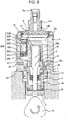
- Fig. 3 shows a vertical sectional view in a direction perpendicular to Fig. 2 .
- Fig. 1 the part enclosed by the broken line shows a pump housing 1 of a high pressure pump, and shows that a damper mechanism and components shown inside the broken line are integrally installed in the pump housing 1 of the high pressure pump.
- a fuel of a fuel tank 20 is pumped up by a feed pump 21 based on a signal from an engine control unit 27 (hereinafter, called an ECU), and pressurized to a suitable feed pressure to be fed to a intake port 10a of the high pressure fuel supply pump through a intake pipe 28.
- an engine control unit 27 hereinafter, called an ECU
- the fuel passing through the intake port 10a passes through a filter 102 fixed inside a intake joint 101, and further through a metal diaphragm damper 9, and intake passages 10b and 10c to reach a intake port 30a of an electromagnetic intake valve mechanism 30 configuring a variable fuel discharge amount control mechanism.
- the intake filter 102 in the intake joint 101 has the function of preventing foreign matters existing in the area from the fuel tank 20 to the intake port 10a from being absorbed into a high pressure fuel supply pump by flow of a fuel.
- the electromagnetic intake valve mechanism 30 includes an electromagnetic coil 30b, and in the state in which the electromagnetic coil 30b is energized, the state in which a spring 33 is compressed is kept with an electromagnetic plunger 30c being moved rightward in Fig. 1 .
- a intake valve member 31 mounted to a tip end of the electromagnetic plunger 30c opens a intake port 32 connecting to a pressure chamber 11 of the high pressure pump.
- the intake valve member 31 is overcome the biasing force of the spring 33, and open the intake port 32, by valve opening force due to the fluid pressure difference.
- the volume of the pressure chamber 11 decreases with compression movement of the plunger 2, but in this state, the fuel which is once sucked into the pressure chamber 11 is spilled to the intake passage 10c (intake port 30a) through the intake valve member 31 in the valve open state again, and therefore, the pressure of the pressure chamber does not rise.
- This process is called a spill process.
- the magnetic biasing force acting on the electromagnetic plunger 30c is erased after a lapse of a specified time (after the lapse of magnetic and mechanical delay time).
- the biasing force by the spring 33 works on the intake valve member 31, and therefore, when the magnetic force acting on the electromagnetic plunger 30c disappears, the intake valve member 31 closes the intake port 32 by the biasing force by the spring 33.
- the intake port 32 is closed, the fuel pressure of the pressure chamber 11 rises with the rising movement of the plunger 2 from this time.
- the amount of the high pressure fuel to be discharged can be controlled.
- the ratio of the spill process is large and the ratio of the discharge process is small during the compression process. Specifically, more fuel is spilled to the intake passage 10c, and less fuel is discharged at a high pressure.
- the timing of canceling energization to the electromagnetic coil 30c is controlled by the command from the ECU.
- the timing of canceling energization to the electromagnetic coil 30c is controlled, and thereby the amount of the fuel which is discharged at a high pressure can be controlled to the amount required by the internal combustion engine.
- the fuel introduced into the fuel intake port 10a is introduced into the pressure chamber 11 of the pump housing 1, and the required amount is pressurized to a high pressure by reciprocating movement of the plunger 2, and is pressure-fed to the common rail 23 from the fuel discharge port 12.
- An injector 24 and a pressure sensor 26 are provided to the common rail 23.
- the injectors 24 the number of which corresponds to the number of cylinders of the internal combustion engine are provided, and open and close in accordance with the control signal of the engine control unit (ECU) 27 to inject a fuel into the cylinders.
- ECU engine control unit
- a concave portion 1A as the pressure chamber 11 is formed in a center, and a hole 11A for fixing the discharge valve mechanism 8 is formed in an area from the inner peripheral wall of the pressure chamber 11 to the discharge port 12. Further, a hole 30A for mounting the electromagnetic intake valve mechanism 30 for supplying a fuel to the pressure chamber 11 is provided in an outer wall of the pump housing on the same axial line as the hole 11a for fixing the discharge valve mechanism 8.
- the axial lines of the hole 11a for fixing the discharge valve mechanism 8 and the hole for mounting the electromagnetic intake valve mechanism 30 are formed in the direction orthogonal to the center axial line of the concave portion 1A as the pressure chamber 11, and the discharge valve mechanism 8 for discharging the fuel to the discharge passage from the pressure chamber 11 is provided.
- the cylinder 6 which guides the reciprocating movement of the plunger 2 is protrude to the pressure chamber.
- the axial lines of the hole 11a for fitting the discharge valve mechanism 8 and the hole 30A for mounting the electromagnetic intake valve mechanism 30 are formed to be the same axial line, but according to this, assembly can be performed straight from the hole 30A for mounting the electromagnetic intake valve mechanism 30 to the hole 11a for fitting the discharge valve mechanism 8.
- the force at the time of press-fitting the discharge valve mechanism 8 can be applied from the hole 30A for mounting the electromagnetic intake valve mechanism 30.
- the diameter of the hole 30A in the minimum diameter portion needs to be configured to be larger than the maximum outside diameter of the discharge valve mechanism 8.
- the discharge valve mechanism 8 is provided at an outlet of the pressure chamber 11.
- the discharge valve mechanism 8 is composed of a seat member (seat member) 8a, a discharge valve 8b, a discharge valve spring 8c and a holding member 8d as a discharge valve stopper.
- the discharge valve 8b In the state without a pressure difference in the fuel between the pressure chamber 11 and the discharge port 12, the discharge valve 8b is in pressure-contact with the seat member 8a by the biasing force by the discharge valve spring 8c and is in the valve closed state. It is not until the fuel pressure in the pressure chamber 11 becomes larger than the fuel pressure of the discharge port 12 by a specific value that the discharge valve 8b opens against the discharge valve spring 8c, and the fuel in the pressure chamber 11 is discharged to the common rail 23 through the discharge port 12.
- the discharge valve 8b When the discharge valve 8b opens, the discharge valve 8b contacts the holding member 8d, and its movement is restricted. Accordingly, the stroke of the discharge valve 8b is properly determined by the holding member 8d. If the stroke is too large, the fuel discharged to the fuel discharge port 12 flows back into the pressure chamber 11 again due to delay in closure of the discharge valve 8b, and therefore, the efficiency as the high pressure pump reduces. Further, the holding member 8d guides the discharge valve 8b so that the discharge valve 8b moves only in the stroke (axial) direction when the discharge valve 8b repeats opening and closing movement. By being configured as above, the discharge valve mechanism 8 functions as a check-valve which restricts the flowing direction of the fuel.
- the high pressure fuel supply pump is fixed to the engine by a flange holder 40, a flange 41 and a bush 43.
- the flange holder 40 is pressure-contacted and fixed to the engine by a set screw 42 via the flange 41.
- the bush 43 exists between the flange 41 and the engine.
- the flange holder 40 is fixed to the pump housing 1 by a screw threaded in an inner periphery, and therefore, the pump housing is fixed to the engine by this.
- the bush 43 is fixed to the flange 41, whereby the flange 41 can be formed into a flat shape without a curved portion as shown in Fig. 2 . Thereby, formation of the flange 41 is facilitated.
- the pump housing 1 is further provided with a relief passage 311 which allows a downstream side of the discharge valve 8b and the intake passage 10c to communicate with.
- the relief passage 311 is provided with a relief valve mechanism 200 which restricts the flow of the fuel to only one direction from the discharge passage to the intake passage 10c, and an inlet of the relief valve mechanism 200 communicates with the downstream side of the discharge valve 8b by a passage not illustrated.
- a relief valve 202 is pressed against a relief valve seat 201 by a relief spring 204 which generates a pressing force, and a set valve opening pressure is set so that when the pressure difference between the inside of the intake chamber and the inside of the relief passage becomes a specified pressure or more, the relief valve 202 separates from the relief valve seat 201 to open.
- the pressure when the relief valve 202 starts to open is defined as the set valve opening pressure.
- the relief valve mechanism 200 is composed of a relief valve housing 206 integrated with the relief valve seat 201, the relief valve 202, a relief presser 203, the relief spring 204 and a relief spring adjuster 205.
- the relief valve mechanism 200 is assembled outside the pump housing 1 as a subassembly, and thereafter, is fixed to the pump housing 1 by press-fitting.
- the relief valve 202, the relief presser 203 and the relief spring 204 are sequentially inserted into the relief valve housing 206, and the relief spring adjuster 205 is fixed to the relief valve housing 206 by press-fitting.
- the set load of the relief spring 204 is determined by the fixing position of the relief spring adjuster 205.
- the valve opening pressure of the relief valve 202 is determined by the set load of the relief spring 204.
- the relief subassembly 200 thus constructed is fixed to the pump housing 1 by press-fitting.
- valve opening pressure of the relief valve 200 is set to a pressure higher than the maximum pressure in the normal operation range of the high pressure fuel supply pump.
- the abnormal high pressure in the common rail 23 which occurs due to a failure of a fuel injection valve which supplies a fuel to the engine, and a failure of the ECU 27 or the like which controls the fuel injection valve, the high pressure fuel supply pump and the like becomes the predetermined valve opening pressure of the relief valve or higher, the fuel passes through the relief passage 211 from the downstream side of the discharge valve 8b and reaches the relief valve 202.
- the fuel which passes through the relief valve 202 is released to the intake passage 10c which is the low pressure portion of a relief passage 208 which is provided in the relief spring adjuster 205. Thereby, the high pressure portion such as the common rail 23 is protected.
- the outer periphery of a cylinder 6 is held by a cylinder holder 7, and the cylinder holder 7 is held inside a flange holder 40.
- a screw 410 threaded on the inner periphery of the flange holder 40 is screwed into a screw 411 which is threaded in the pump housing 1, and thereby, the cylinder 6 is fixed to the pump housing 1 via the cylinder holder 7.
- the cylinder 6 holds the plunger 2, which advances and retreats in the pressure chamber 11, slidably along the advancing and retreating direction.
- a tappet 3 which converts the rotating movement of a cam 5 attached to a camshaft of the engine into vertical movement and transmits the vertical movement to the plunger 2 is provided at a lower end of the plunger 2.
- the plunger 2 is in pressure-contact with the tappet 3 by a spring 4 via a retainer 15.
- the retainer 15 is fixed to the plunger 2 by press-fitting. Thereby, with rotating movement of the cam 5, the plunger 2 can be vertically advanced and retreated (reciprocated).
- a plunger seal 13 held at the lower end portion of the inner periphery of the cylinder holder 7 is installed in the state in which it is slidably in contact with the outer periphery of the plunger 2 at the lower end portion in the drawing of the cylinder 6, whereby the fuel in the seal chamber 10f is prevented from flowing to the tappet 3 side, that is, to the inside of the engine.
- lubricant oil also including engine oil which lubricates the sliding portion in the engine room is prevented from flowing inside the pump housing 1.
- the intake passage 10c is connected to the seal chamber 10f via the intake passage 10d, and the intake passage 10e provided in the cylinder 6, and the seal chamber 10f is always connected to the pressure of the sucked fuel.
- the fuel in the pressure chamber 11 is pressed to a high pressure, a very small amount of high pressure fuel flows into the seal chamber 10f through a slide clearance of the cylinder 6 and the plunger 2, but the high pressure fuel which flows in is released to intake pressure, and therefore, the plunger seal 13 is not broken due to a high pressure.
- the plunger 2 is composed of a large diameter portion 2a which slides with the cylinder 6, and a small diameter portion 2b which slides with the plunger seal 13.
- the diameter of the large diameter portion 2a is set to be larger than the diameter of the small diameter portion 2b, and the large diameter portion 2a and the small diameter portion 2b are set to be coaxial with each other.
- the diameter of the large diameter portion 2a is set at 10 mm, and the diameter of the small diameter portion 2b is set at 6 mm.
- Fig. 4 is a system diagram of the high pressure fuel supply pump in the present example not covered by the claimed invention.
- Fig. 5 shows the relationship of the movement of the plunger 2 and the movement of the fuel inside the high-pressure fuel supply pump.
- Fig. 6 shows the relationship of an area ratio of the large diameter portion 2a and the small diameter portion 2b of the plunger 2, and the pressure pulsation which occurs in the low pressure pipe 28.
- Fig. 4 shows a flow of the fuel inside the high pressure fuel supply pump in the present example not covered by the claimed invention.
- the fuel which flows inside the high pressure fuel supply pump from the intake port 10a passes through the metal damper 9 (3), part of it flows into the pressure chamber 11 through the intake valve member 31 from the intake passage 10c (1), and the remaining part flows into the seal chamber 10f via the intake passage 10d from the intake passage 10c (2).
- the flow of the fuel in the direction of the arrow in Fig. 7 is defined as positive value.
- a negative value means the flow of the fuel in the direction opposite to the arrow.
- Fig. 5 shows the relationship of the movement of the plunger 2, and the fuel flows (1), (2) and (3).
- TDC abbreviation of TOP DEAD CENTER
- BDC abbreviation of BOTTOM DEAD CENTER
- S in the drawing represents the ratio of "sectional area of the small diameter portion 2b" to "sectional area of the large diameter portion 2a" in the plunger 2.
- the diameter of the large diameter portion 2a is 10 mm
- the diameter of the small diameter portion 2b is 6 mm
- T represents the ratio of the suction process in the ascending process of the plunger 2.
- the ratio of the intake process in the rising process of the plunger 2 is 1-T.
- This mode will be called full discharge.
- the magnitude of the intake pressure pulsation which occurs to the intake pipe 28 is determined by the sum of the following two amounts.
- Fig. 6 shows the relationship of T and the above described (c).
- the pressure pulsation becomes larger. This is because the fuel is also sucked into the seal chamber 10f at the same time when the fuel is discharged at a high pressure to the common rail 23 from the pressure chamber 11 in the discharge process, and therefore, the fuel flows into the intake passage 10c from the intake port 10a.
- setting S to be small means setting the small diameter portion 2b of the plunger 2 to be small, and if the small diameter portion 2b is made too small, the strength of the small diameter portion 2a becomes insufficient to break the plunger 2.
- the diameter of the large diameter portion 2a is set at 10 mm
- the diameter of the small diameter portion 2b is set at 6 mm
- Fig. 7 is an enlarged view and a perspective view of the metal diaphragm damper 9 portion for absorbing pressure pulsation in Fig. 2 .
- Fig. 8 is an enlarged view and a perspective view of the metal diaphragm damper 9 portion for absorbing pressure pulsation in Fig. 3 .
- Fig. 9 shows an assembly procedure when fixing the damper unit 118 to the pump housing 1.
- the damper unit 118 is configured by two metal diaphragms 9a and 9b, and entire outer peripheries of them are fixed to each other by welding at a weld portion 9d with gas 9c being sealed in the space between both the diaphragms.
- a plane portion is provided inside the weld portion 9d, and by sandwiching this portion, the damper unit is installed in the low pressure passage of the high pressure fuel supply pump.
- the intake passages 10b and 10c are formed the pass throught-surrounding of the damper unit.
- the metal diaphragm damper 9 When low pressure pulsation is loaded on both surfaces of the metal diaphragm damper 9, the metal diaphragm damper 9 changes its volume, and thereby, reduces the low pressure pulsation.
- the metal diaphragm damper 9 is vertically held by an upper holding member 104 and a lower holding member 105, and at the time of assembly, the metal diaphragm damper 9 is unitized in this state first to form the damper unit 118, as in Fig. 9 .
- the upper holding member 104 has a curl portion 119, and an upper end of the lower holding member 105 faces the curl portion 119 to hold the flat plate portion of the metal diaphragm damper 9.
- the diameters of the contact portion of the upper holding member 104 and the metal diaphragm damper 9 and the contact portion of the lower holding member 105 and the metal diaphragm damper 9 are equal, and they are in contact over the entire circumference.
- An inner peripheral portion 110 of the upper holding member 104 and an outer peripheral portion 111 of the lower holding member 105 are fixed by press fit, and are fixed to each other at the peripheral edge portion at the outer side from the metal diaphragm damper 9, and further, the weld portion 9d of the metal diaphragm damper 9 is disposed in a space 107 formed between the upper holding member 104 and the lower holding member 105.
- the metal diaphragm damper 9 can be fixed without generating stress in the weld portion 9d of the metal diaphragm damper 9.
- the metal diaphragm damper 9 is held and fixed over the entire circumference to be vertically symmetrical, and therefore, stress does not occur by fixing except for the fixing portion.
- three members that are the upper and lower holding members 104 and 105 and the metal diaphragm damper 9 are easily positioned in the diameter direction by the inner peripheral portion 110 of the upper holding member 104.
- the damper unit 118 which is configured as described above is housed in a concave portion formed in the pump housing 1. At this time, an outer peripheral portion 116 of the upper holding member 104 and an inner peripheral portion 117 of the pump housing 1 are positioned in the diameter direction by loose fitting instead of press-fitting.
- the damper cover 14 is formed into a cup shape, and a cylindrical outer surface at its open side is fixed to the pump housing 1 by welding 106.
- the damper cover 14 has a projected portion 120 which is projected to an inner side, and the upper holding member 104 is in contact with the damper cover 14 at a contact portion 114.
- the projected portion 120 is in an annular protruded shape having a damper cover omitted portion 112 with a part of it being omitted, and at the damper cover omitted portion 112, the damper cover 14 and the damper unit 118 are not in contact with each other.
- a recess end surface 115 of the pump housing 1 is in contact with the lower holding member 105, and has a annular structure with a part of it being omitted by a body omitted portion 113, and at the body omitted portion 113, the pump housing 1 and the damper unit 118 are not in contact with each other.
- the inner peripheral portion 117 is also omitted, and the body omitted portion 113 does not contribute to positioning of the upper holding member 104 and the outer peripheral portion 116.
- the damper unit 118 is fixed in such a way as to hold the upper holding member 104 by the damper cover 14 from the upper side and hold the lower holding member 105 from the lower side. This is fixed in the direction to promote press-fitting of the upper holding member 104 and the lower holding member 105.
- the intake passage 10b between the damper cover 14 and the metal diaphragm damper 9 communicates with the annular space 121 between the damper cover 14 and the upper holding member 104 by the damper cover omitted portion 112.
- the intake passage 10c between the pump housing 1 and the metal diaphragm damper 9 also communicates with the annular space 121 between the damper cover 14 and the upper holding member 104 by the body omitted portion 113.
- the damper unit 118 is held in the state sandwiched by the damper cover 14 and the pump housing 1, and at the same time, the intake passage 10b and the intake passage 10c communicate with each other.
- the fuel which flows into the high pressure fuel supply pump from the intake port 10a flows into the intake passage 10b, and subsequently into the intake passage 10c, and therefore, the fuel flow (3) in Fig. 4 all passes through the metal diaphragm damper 9.
- the fuel spreads over both surfaces of the metal diaphragm damper 9, and the fuel pressure pulsation can be efficiently reduced by the metal diaphragm damper 9.
- the damper cover 14 is made by working a rolled steel seat by pressing, and therefore, the seat thickness of the cover is uniform anywhere.
- the damper cover 14 is temporarily press-fitted to the pump housing 1 by the press-fitting portion 122 first.
- the projected portion 120 of the damper cover 14 and the upper holding member 104 are already in contact with each other at the contact portion 114, and the recess end surface 115 of the pump housing 1 and the lower holding member 105 are in contact with each other. Therefore, the damper unit 118 is rigidly fixed in such a manner as to be sandwiched by the pump housing 1 and the damper cover 14.
- the press-fitting portion 122 is liquid-tightly fixed by applying welding to the entire circumference in such a way as to penetrate through the damper cover 14 at the weld portion 106. Thereby, the inside and the outside of the high pressure fuel supply pump are completely shut off to be liquid-tight at the weld portion 106, so that the fuel is sealed against the outside.
- the damper cover 14 displaces in the direction to press the damper unit 118 with the pump housing 1 and the damper cover 14, and therefore, the holding force of the damper unit 118 does not attenuate even after welding.
- the outside diameter of the relief valve housing 206 is fixed to the pump housing 1 by press-fitting.
- the press-fitting load is set at such interference as to prevent the relief valve housing 206 from slipping upward in the drawing by the high-pressure fuel in the relief passage 211.
- the mechanism is such that even if the relief valve housing 206 slips upward in the drawing by the high-pressure fuel due to some errors, the relief valve housing 206 contacts the lower holding member 105 first, where the relief valve housing 206 is prevented from slipping off.
- the relief passage 211 which is the hole in which the relief valve housing 206 is press-fitted is in the positional relationship to be superimposed on the recess end surface 115 of the pump housing 1, and before the damper unit 118 is inserted into the pump housing 1, the relief valve mechanism 200 is fixed to the relief passage 211 by press-fitting. At this time, the relief valve mechanism 200 is fixed by press-fitting so that the upper end surface of the relief valve housing 206 is on the lower side from the recess end surface 115 of the pump housing 1.
- the intake joint 101 is fixed to the damper cover omitted portion 112 of the damper cover 14 by the weld portion 103.
- the filter 102 is fixed to the intake joint 10a.
- the intake port 10a is formed in the intake joint 101. The fuel which flows into the high-pressure fuel supply pump all passes through the filter.
- the difference between the second example not covered by the claimed invention and the first example not covered by the claimed invention is only the position of the intake joint 101.
- the parts except for this are the same as those in the first example not covered by the claimed invention, and the described codes and numerals are all common to those of the first example not covered by the claimed invention.
- Fig. 10 shows a system diagram of the high-pressure fuel supply pump in the present example not covered by the claimed invention.
- Fig. 11 is a vertical sectional view of the high-pressure fuel supply pump in the present example not covered by the claimed invention.
- the intake joint 101 is mounted to the pump housing 1, and is fixed by the weld portion 103.
- the intake port 10a is formed in the intake joint 101, and the filter 102 is fixed into the intake joint 101.
- the fuel which flows into the high-pressure fuel supply pump all passes through the filter 102.
- the metal diaphragm damper 9 exists between the pressure chamber 11 and the intake passage 10d.
- the metal diaphragm damper 9 mainly absorbs and restrains the pressure pulsation which generates in the fuel (1) which goes to the pressure chamber 11 from the intake passage 10d.
- the intake passage 10b2 and the intake passage 10c communicate with each other through the annular space 121 as in example 1 not covered by the claimed invention. Thereby, the fuel sufficiently spreads over both surfaces of the metal diaphragm damper 9, and therefore, the pressure pulsation can be sufficiently restrained.
- the position of the intake joint can be properly selected in accordance with the layout of each engine.
- the high-pressure fuel supply pump can be kept compact and light without increasing the size and weight of the high-pressure fuel supply pump.
- the difference between the third example not covered by the claimed invention and the first example not covered by the claimed invention is only a projection length 123 of the lower holding member 105 from the upper holding member 104.
- the parts except for this are the same as those in the first example not covered by the claimed invention, and the described codes and numerals are all common to the first example not covered by the claimed invention.
- Fig. 12 is a vertical sectional view of a high-pressure fuel supply pump in the present example not covered by the claimed invention, and is an enlarged view of the metal diaphragm damper 9 portion for absorbing pressure pulsation.
- the lower holding member 105 projects to the lower side in the drawing from the upper holding member 104 as in the first example not covered by the claimed invention.
- the projection amount is set as 123.
- the upper holding member 104 contacts the damper cover 14, whereas the lower holding member 105 contacts the pump housing 1, which is the same as in the first example not covered by the claimed invention.
- the projection amount 123 is set to be as small as 0.5 mm or less.
- the press-fitting portion of the upper holding member 104 and the lower holding member 105 can be set to be sufficiently long, and therefore, even if a variation (individual difference) occurs to the fixing force when the damper unit 118 is fixed to between the damper cover 14 and the pump housing 1, the variation can be absorbed, and a variation of the force with which the upper holding member 104 and the lower holding member 105 pinch the metal diaphragm damper 9 can be made small.
- the damper cover 14 displaces in the direction to press the damper unit 118 by the pump housing 1 and the damper cover 14, and a variation (individual difference) also occurs to the displacement.
- the variation of the force with which the upper holding member 104 and the lower holding member 105 fix the metal diaphragm damper 9, which generates due to the variation (individual difference) of this displacement can be made small.
- the difference between the fourth example not covered by the claimed invention and the first example not covered by the claimed invention is that the recess end surface 115 of the pump housing 1 and a lower end portion 124 of the upper holding member 104 are in contact with each other, contrary to the invention, but the pump housing 1 and the lower holding member 105 are not in contact with each other.
- the parts except for this are the same as those in the first example not covered by the claimed invention, and the described codes and numerals are all common to the first example not covered by the claimed invention.
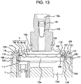
- Fig. 13 is a vertical sectional view of a high pressure fuel supply pump in the present example not covered by the claimed invention, and is an enlarged view of the metal diaphragm damper 9 portion for absorbing pressure pulsation.
- the damper cover 14 and the upper holding member 104 are in contact with each other at the contact portion 114. Meanwhile, the recess end surface 115 of the pump housing 1 and the lower end portion 124 of the upper holding member 104 are in contact with each other, contrary to the invention.
- the metal diaphragm damper 9 is vertically sandwiched by only mutual press-fitting force of the upper holding member 104 and the lower holding member 105.
- the relief valve housing 206 slips upward in the drawing by the high pressure fuel due to a certain error, the relief valve housing 206 and the upper holding member 104 contact each other at first, where the relief valve housing 206 is prevented from slipping off.
Description
- The present invention relates to a mechanism for reducing pressure pulsation which is housed in a damper chamber provided in a low pressure fuel passage leading to a pressure chamber of a high pressure fuel supply pump.
- Further, the present invention also relates to a high pressure fuel supply pump of an internal combustion engine integrally including such a mechanism for reducing pressure pulsation.
- A conventional mechanism for reducing fuel pressure pulsation is configured to hold a metal damper which is formed by joining two metal diaphragms and sealing gas inside the two metal diaphragms, between a damper chamber provided in a pump main body and a cover fitted onto the main body, and is housed in the damper chamber formed in a low pressure fuel passage leading to a pressure chamber of a high pressure fuel supply pump.
- More specifically, two metal diaphragms are welded at their outer peripheries, have a disk-shaped convex portion with gas sealed in a center, and include an annular flat plate portion in which the two metal diaphragms are superimposed on each other, between the weld portion at the outer periphery and the disk-shaped convex portion. There are known a damper mechanism in which both outer surfaces of the flat plate portion are held by thick portions provided at a cover and a main body, or a damper mechanism in which elastic members are sandwiched between the cover and the annular flat plate portion and between the main body and the annular flat portion to hold them.
- Further, there are known high pressure fuel supply pumps including such mechanisms for reducing fuel pressure pulsation (see
JP-A-2004-138071 JP-A-2006-521487 JP-A-2003-254191 JP-A-2005-42554 DE 10 2004 047601 A1 a high pressure fuel supply pump is described with a housing having an inlet.WO 2005/031161 A2 discloses a high-pressure fuel pump, comprising a housing and at least one low-pressure connection on the intake side. The fluid pump further comprises a pressure damper which dampens pressure variations on the intake side while encompassing at least one compressible volume that is located directly in the flow path between the low-pressure connection and the intake valve. - [Patent Document 1]
JP-A-2004-138071 - [Patent Document 2]
JP-A-2006-521487 - [Patent Document 3]
JP-A-2003-254191 - [Patent Document 4]
JP-A-2005-42554 - [Patent Document 5]
DE 10 2004 047601 A1 - [Patent Document 6]
WO 2005/031161 A2 - In the above described prior art, at the process of assembly operation of a metal damper configured by metal diaphragms, as a damper mechanism for reducing pressure pulsation, into a low pressure fuel passage and a high pressure fuel supply pump, a number of components need to be installed and fixed into a body at the same time, and there arises the problem of easily causing component omission and assembly error.
- An object of the present invention is to reduce the number of components at the time of operation of installing a metal diaphragm damper as a damper mechanism for reducing pressure pulsation into a low pressure fuel passage and prevent component omission and assembly error.
- Further, an object of the present invention is to reduce the number of components at the time of assembling a damper mechanism for reducing pressure pulsation to a high pressure fuel supply pump, and prevent component omission and assembly error in the high pressure fuel supply pump including the damper mechanism for reducing pressure pulsation.
- A high pressure fuel pump comprising a pump housing, a pressure chamber provided in the pump housing, a damper chamber formed by the pump housing and a damper cover. A metal diaphragm damper is arranged in the damper chamber and a pair of an upper holding member and a lower holding member are vertically sandwiching the metal diaphragm damper. The upper holding member is in contact with the damper cover, and the lower holding member is in contact with the pump housing. A recess end surface of the pump housing and the lower holding member are in contact with each other, wherein the weld portion is fixing the damper cover to the pump housing at an entire circumference of the press-fitting portion, for being liquid-tightly fixed by applying welding to the entire circumference at a weld portion. At a press-fitting portion of the pump housing, an annular surface of the damper cover is temporarily press-fitted to an annular surface of the pump housing, wherein at this timing, a projected portion of the damper cover and the upper holding member are already in contact with each other at the contact portion, and wherein the weld portion penetrates through the damper cover to the pump housing at an entire circumference of the press-fitting portion.
- A method for manufacturing a high pressure fuel pump, the high fuel pump comprising a pump housing, a pressure chamber provided in the pump housing, a damper chamber formed by the pump housing and a damper cover. A metal diaphragm damper is arranged in the damper chamber, and a pair of an upper holding member and a lower holding member are vertically sandwiching the metal diaphragm damper. The upper holding member is in contact with the damper cover and the lower holding member is in contact with the pump housing. At a press-fitting portion of the pump housing, an annular surface of the damper cover is temporarily press-fitted to an annular surface of the pump housing, wherein at this timing, a projected portion of the damper cover and the upper holding member are already in contact with each other at the contact portion. Furthermore, the recess end surface of the pump housing and the lower holding member are in contact with each other. The weld portion is fixing the damper cover to the pump housing at an entire circumference of the press-fitting portion for being liquid-tightly fixed by applying welding to the entire circumference at a weld portion, and the weld portion penetrates through the damper cover to the pump housing at an entire circumference of the press-fitting portion.
- According to the invention characterized by the above mentioned features, component omission and assembly error can be prevented by reducing the number of components which are installed or fixed into a body at the same time at a time of operation of installing a metal diaphragm damper as a damper mechanism for reducing pressure pulsation in a low pressure fuel passage or a high pressure fuel supply pump.
-
-
Fig. 1 is one example of a fuel supply system using a high pressure fuel supply pump according to a first example not covered by the claimed invention. -
Fig. 2 is a vertical sectional view of the high pressure fuel supply pump according to the first example not covered by the claimed invention. -
Fig. 3 shows a vertical sectional view of the high pressure fuel supply pump according to the first example not covered by the claimed invention, and shows a vertical sectional view of the position ofFig. 2 which is rotated by 90°. -
Fig. 4 is one example of a fuel supply system using the high pressure fuel supply pump according to the first example not covered by the claimed invention, and especially shows a flow of a fuel in the high pressure fuel supply pump in detail. -
Fig. 5 is a diagram showing a generation mechanism of intake pressure pulsation which generates by the high pressure fuel supply pump according to the first example not covered by the claimed invention. -
Fig. 6 is a diagram showing the relationship of the intake pressure pulsation which generates by the high pressure fuel supply pump by the first example not covered by the claimed invention and an area of asmall diameter portion 2a of aplunger 2. -
Figs. 7 (a) and (b) are vertical sectional views of the high pressure fuel supply pump according to the first example not covered by the claimed invention, and are an enlarged view (a) and a perspective view (b) especially of a portion relating to themetal diaphragm damper 9. -
Figs. 8 (a) and (b) are vertical sectional views of the high pressure fuel supply pump according to the first example not covered by the claimed invention, express a section perpendicular toFig. 7 , and are an enlarged view (a) and a perspective view (b) especially of the portion relating to themetal diaphragm damper 9. -
Fig. 9 is a view showing adamper unit 118 at a time of assembling the high pressure fuel supply pump according to an embodiment in which the present invention is carried out, and a method for assembling thedamper unit 118 to thepump housing 1 and thedamper cover 14. -
Fig. 10 shows one example of a system diagram of a high pressure fuel supply pump according to a second example not covered by the claimed invention, and especially shows a flow of a fuel in the high pressure fuel supply pump in detail. -
Fig. 11 is a vertical sectional view of the high pressure fuel supply pump according to the second example not covered by the claimed invention. -
Fig. 12 is a vertical sectional view of a high pressure fuel supply pump according to a third example not covered by the claimed invention, and is an enlarged view of a periphery of ametal diaphragm damper 9 portion. -
Fig. 13 is a vertical sectional view of a high pressure fuel supply pump according to a fourth example not covered by the claimed invention, and an enlarged view of a periphery of ametal diaphragm damper 9 portion. - Hereinafter, an embodiment and examples not covered by the claimed invention will be described with use of the drawings.
- A first example not covered by the claimed invention will be described.
- First, based on
Figs. 1 to 3 , a basic operation of a high pressure fuel supply pump will be described. -
Fig. 1 shows a fuel supply system including a high pressure fuel supply pump. -
Fig. 2 shows a vertical sectional view of the high pressure fuel supply pump. -
Fig. 3 shows a vertical sectional view in a direction perpendicular toFig. 2 . - In
Fig. 1 , the part enclosed by the broken line shows apump housing 1 of a high pressure pump, and shows that a damper mechanism and components shown inside the broken line are integrally installed in thepump housing 1 of the high pressure pump. - A fuel of a
fuel tank 20 is pumped up by afeed pump 21 based on a signal from an engine control unit 27 (hereinafter, called an ECU), and pressurized to a suitable feed pressure to be fed to aintake port 10a of the high pressure fuel supply pump through aintake pipe 28. - The fuel passing through the
intake port 10a passes through afilter 102 fixed inside aintake joint 101, and further through ametal diaphragm damper 9, andintake passages intake port 30a of an electromagneticintake valve mechanism 30 configuring a variable fuel discharge amount control mechanism. - The
intake filter 102 in theintake joint 101 has the function of preventing foreign matters existing in the area from thefuel tank 20 to theintake port 10a from being absorbed into a high pressure fuel supply pump by flow of a fuel. - The details of the
metal diaphragm damper 9 for reducing pressure pulsation will be described later. - The electromagnetic
intake valve mechanism 30 includes anelectromagnetic coil 30b, and in the state in which theelectromagnetic coil 30b is energized, the state in which aspring 33 is compressed is kept with anelectromagnetic plunger 30c being moved rightward inFig. 1 . - At this time, a
intake valve member 31 mounted to a tip end of theelectromagnetic plunger 30c opens aintake port 32 connecting to apressure chamber 11 of the high pressure pump. - When the
electromagnetic coil 30b is not energized, and fluid differential pressure does not exist between theintake passage 10c (intake port 30a) and thepressure chamber 11, theintake valve member 31 is acted in a valve closing direction by the biasing force of thespring 33, and theintake port 32 is in a closed state. - When a
plunger 2 is in a intake process in which it displaces downward inFig. 2 by rotation of a cam which will be described later, the volume of thepressure chamber 11 increases, and the fuel pressure in thepressure chamber 11 reduces. When the fuel pressure in thepressure chamber 11 becomes lower than the pressure of theintake passage 10c (intake port 30a) in this process, a valve opening force (force to displace theintake valve member 31 rightward inFig. 1 ) by a fluid pressure difference of the fuel occurs to theintake valve member 31. - The
intake valve member 31 is overcome the biasing force of thespring 33, and open theintake port 32, by valve opening force due to the fluid pressure difference. - When a control signal from the
ECU 27 is applied to the electromagneticintake valve mechanism 30 in this state, an electric current flows into theelectromagnetic coil 30b of the electromagneticintake valve mechanism 30, theelectromagnetic plunger 30c moves rightward inFig. 1 by the magnetic biasing force which occurs by this, and thespring 33 is kept in the compressed state. As a result, the state in which theintake valve member 31 opens theintake port 32 is kept. - When the
plunger 2 finishes the intake process while keeping the application state of the input voltage to the electromagneticintake valve mechanism 30, and theplunger 2 moves to the compression process in which it displaces upward inFig. 2 , theintake valve member 31 is still kept open since the magnetic biasing force remains to be kept. - The volume of the
pressure chamber 11 decreases with compression movement of theplunger 2, but in this state, the fuel which is once sucked into thepressure chamber 11 is spilled to theintake passage 10c (intake port 30a) through theintake valve member 31 in the valve open state again, and therefore, the pressure of the pressure chamber does not rise. - When the control signal from the
ECU 27 is cleared in this state, and energization to theelectromagnetic coil 30b is shut off, the magnetic biasing force acting on theelectromagnetic plunger 30c is erased after a lapse of a specified time (after the lapse of magnetic and mechanical delay time). The biasing force by thespring 33 works on theintake valve member 31, and therefore, when the magnetic force acting on theelectromagnetic plunger 30c disappears, theintake valve member 31 closes theintake port 32 by the biasing force by thespring 33. When theintake port 32 is closed, the fuel pressure of thepressure chamber 11 rises with the rising movement of theplunger 2 from this time. When the fuel pressure becomes the pressure of thefuel discharge port 12 or higher, high pressure discharge of the fuel remaining in thepressure chamber 11 is performed via adischarge valve unit 8, and the fuel is supplied to acommon rail 23. This process is called a discharge process. Specifically, the compression process of the plunger 2 (the rising process from the bottom dead center to the top dead center) is configured by the spill process and the discharge process. - By controlling the timing of canceling energization to the
electromagnetic coil 30c of the electromagneticintake valve mechanism 30, the amount of the high pressure fuel to be discharged can be controlled. - If the timing of canceling energization to the
electromagnetic coil 30c is made early, the ratio of the spill process is small and the ratio of the discharge process is large during the compression process. - More specifically, less fuel is spilled to the
intake passage 10c (intake port 30a), and more fuel is discharged at a high pressure. - Meanwhile, if the timing of canceling the input voltage is made later, the ratio of the spill process is large and the ratio of the discharge process is small during the compression process. Specifically, more fuel is spilled to the
intake passage 10c, and less fuel is discharged at a high pressure. The timing of canceling energization to theelectromagnetic coil 30c is controlled by the command from the ECU. - By the configuration as above, the timing of canceling energization to the
electromagnetic coil 30c is controlled, and thereby the amount of the fuel which is discharged at a high pressure can be controlled to the amount required by the internal combustion engine. - Thus, the fuel introduced into the
fuel intake port 10a is introduced into thepressure chamber 11 of thepump housing 1, and the required amount is pressurized to a high pressure by reciprocating movement of theplunger 2, and is pressure-fed to thecommon rail 23 from thefuel discharge port 12. - An
injector 24 and apressure sensor 26 are provided to thecommon rail 23. Theinjectors 24 the number of which corresponds to the number of cylinders of the internal combustion engine are provided, and open and close in accordance with the control signal of the engine control unit (ECU) 27 to inject a fuel into the cylinders. - In the
pump housing 1, aconcave portion 1A as thepressure chamber 11 is formed in a center, and ahole 11A for fixing thedischarge valve mechanism 8 is formed in an area from the inner peripheral wall of thepressure chamber 11 to thedischarge port 12. Further, ahole 30A for mounting the electromagneticintake valve mechanism 30 for supplying a fuel to thepressure chamber 11 is provided in an outer wall of the pump housing on the same axial line as the hole 11a for fixing thedischarge valve mechanism 8. - The axial lines of the hole 11a for fixing the
discharge valve mechanism 8 and the hole for mounting the electromagneticintake valve mechanism 30 are formed in the direction orthogonal to the center axial line of theconcave portion 1A as thepressure chamber 11, and thedischarge valve mechanism 8 for discharging the fuel to the discharge passage from thepressure chamber 11 is provided. - Further, the
cylinder 6 which guides the reciprocating movement of theplunger 2 is protrude to the pressure chamber. - In the first example not covered by the claimed invention, the axial lines of the hole 11a for fitting the
discharge valve mechanism 8 and thehole 30A for mounting the electromagneticintake valve mechanism 30 are formed to be the same axial line, but according to this, assembly can be performed straight from thehole 30A for mounting the electromagneticintake valve mechanism 30 to the hole 11a for fitting thedischarge valve mechanism 8. Alternatively, the force at the time of press-fitting thedischarge valve mechanism 8 can be applied from thehole 30A for mounting the electromagneticintake valve mechanism 30. In this case, the diameter of thehole 30A in the minimum diameter portion needs to be configured to be larger than the maximum outside diameter of thedischarge valve mechanism 8. - The
discharge valve mechanism 8 is provided at an outlet of thepressure chamber 11. Thedischarge valve mechanism 8 is composed of a seat member (seat member) 8a, adischarge valve 8b, adischarge valve spring 8c and a holdingmember 8d as a discharge valve stopper. - In the state without a pressure difference in the fuel between the
pressure chamber 11 and thedischarge port 12, thedischarge valve 8b is in pressure-contact with theseat member 8a by the biasing force by thedischarge valve spring 8c and is in the valve closed state. It is not until the fuel pressure in thepressure chamber 11 becomes larger than the fuel pressure of thedischarge port 12 by a specific value that thedischarge valve 8b opens against thedischarge valve spring 8c, and the fuel in thepressure chamber 11 is discharged to thecommon rail 23 through thedischarge port 12. - When the
discharge valve 8b opens, thedischarge valve 8b contacts the holdingmember 8d, and its movement is restricted. Accordingly, the stroke of thedischarge valve 8b is properly determined by the holdingmember 8d. If the stroke is too large, the fuel discharged to thefuel discharge port 12 flows back into thepressure chamber 11 again due to delay in closure of thedischarge valve 8b, and therefore, the efficiency as the high pressure pump reduces. Further, the holdingmember 8d guides thedischarge valve 8b so that thedischarge valve 8b moves only in the stroke (axial) direction when thedischarge valve 8b repeats opening and closing movement. By being configured as above, thedischarge valve mechanism 8 functions as a check-valve which restricts the flowing direction of the fuel. - Further, the high pressure fuel supply pump is fixed to the engine by a
flange holder 40, aflange 41 and abush 43. Theflange holder 40 is pressure-contacted and fixed to the engine by aset screw 42 via theflange 41. Thebush 43 exists between theflange 41 and the engine. Theflange holder 40 is fixed to thepump housing 1 by a screw threaded in an inner periphery, and therefore, the pump housing is fixed to the engine by this. - The
bush 43 is fixed to theflange 41, whereby theflange 41 can be formed into a flat shape without a curved portion as shown inFig. 2 . Thereby, formation of theflange 41 is facilitated. - The
pump housing 1 is further provided with a relief passage 311 which allows a downstream side of thedischarge valve 8b and theintake passage 10c to communicate with. - The relief passage 311 is provided with a
relief valve mechanism 200 which restricts the flow of the fuel to only one direction from the discharge passage to theintake passage 10c, and an inlet of therelief valve mechanism 200 communicates with the downstream side of thedischarge valve 8b by a passage not illustrated. - Hereinafter, an operation of the
relief valve mechanism 200 will be described. Arelief valve 202 is pressed against arelief valve seat 201 by arelief spring 204 which generates a pressing force, and a set valve opening pressure is set so that when the pressure difference between the inside of the intake chamber and the inside of the relief passage becomes a specified pressure or more, therelief valve 202 separates from therelief valve seat 201 to open. Here, the pressure when therelief valve 202 starts to open is defined as the set valve opening pressure. - The
relief valve mechanism 200 is composed of arelief valve housing 206 integrated with therelief valve seat 201, therelief valve 202, arelief presser 203, therelief spring 204 and arelief spring adjuster 205. Therelief valve mechanism 200 is assembled outside thepump housing 1 as a subassembly, and thereafter, is fixed to thepump housing 1 by press-fitting. - First, the
relief valve 202, therelief presser 203 and therelief spring 204 are sequentially inserted into therelief valve housing 206, and therelief spring adjuster 205 is fixed to therelief valve housing 206 by press-fitting. The set load of therelief spring 204 is determined by the fixing position of therelief spring adjuster 205. The valve opening pressure of therelief valve 202 is determined by the set load of therelief spring 204. Therelief subassembly 200 thus constructed is fixed to thepump housing 1 by press-fitting. - In this case, the valve opening pressure of the
relief valve 200 is set to a pressure higher than the maximum pressure in the normal operation range of the high pressure fuel supply pump. - The abnormal high pressure in the
common rail 23 which occurs due to a failure of a fuel injection valve which supplies a fuel to the engine, and a failure of theECU 27 or the like which controls the fuel injection valve, the high pressure fuel supply pump and the like becomes the predetermined valve opening pressure of the relief valve or higher, the fuel passes through therelief passage 211 from the downstream side of thedischarge valve 8b and reaches therelief valve 202. The fuel which passes through therelief valve 202 is released to theintake passage 10c which is the low pressure portion of arelief passage 208 which is provided in therelief spring adjuster 205. Thereby, the high pressure portion such as thecommon rail 23 is protected. - The outer periphery of a
cylinder 6 is held by acylinder holder 7, and thecylinder holder 7 is held inside aflange holder 40. A screw 410 threaded on the inner periphery of theflange holder 40 is screwed into a screw 411 which is threaded in thepump housing 1, and thereby, thecylinder 6 is fixed to thepump housing 1 via thecylinder holder 7. Thecylinder 6 holds theplunger 2, which advances and retreats in thepressure chamber 11, slidably along the advancing and retreating direction. - A
tappet 3 which converts the rotating movement of acam 5 attached to a camshaft of the engine into vertical movement and transmits the vertical movement to theplunger 2 is provided at a lower end of theplunger 2. Theplunger 2 is in pressure-contact with thetappet 3 by aspring 4 via aretainer 15. Theretainer 15 is fixed to theplunger 2 by press-fitting. Thereby, with rotating movement of thecam 5, theplunger 2 can be vertically advanced and retreated (reciprocated). - Further, a
plunger seal 13 held at the lower end portion of the inner periphery of thecylinder holder 7 is installed in the state in which it is slidably in contact with the outer periphery of theplunger 2 at the lower end portion in the drawing of thecylinder 6, whereby the fuel in theseal chamber 10f is prevented from flowing to thetappet 3 side, that is, to the inside of the engine. At the same time, lubricant oil (also including engine oil) which lubricates the sliding portion in the engine room is prevented from flowing inside thepump housing 1. - Here, the
intake passage 10c is connected to theseal chamber 10f via theintake passage 10d, and theintake passage 10e provided in thecylinder 6, and theseal chamber 10f is always connected to the pressure of the sucked fuel. When the fuel in thepressure chamber 11 is pressed to a high pressure, a very small amount of high pressure fuel flows into theseal chamber 10f through a slide clearance of thecylinder 6 and theplunger 2, but the high pressure fuel which flows in is released to intake pressure, and therefore, theplunger seal 13 is not broken due to a high pressure. - Further, the
plunger 2 is composed of alarge diameter portion 2a which slides with thecylinder 6, and asmall diameter portion 2b which slides with theplunger seal 13. The diameter of thelarge diameter portion 2a is set to be larger than the diameter of thesmall diameter portion 2b, and thelarge diameter portion 2a and thesmall diameter portion 2b are set to be coaxial with each other. In the case of the present example not covered by the claimed invention, the diameter of thelarge diameter portion 2a is set at 10 mm, and the diameter of thesmall diameter portion 2b is set at 6 mm. By setting like this, the pressure pulsation at the low pressure side, which occurs at the low pressure side upstream from the electromagneticintake valve mechanism 30 with vertical movement of the plunger, can be reduced. - Hereinafter, a mechanism which reduces the pressure pulsation at the low pressure side by configuring the
plunger 2 by thelarge diameter portion 2a and thesmall diameter portion 2b will be described by usingFigs. 4 ,5 and6 . -
Fig. 4 is a system diagram of the high pressure fuel supply pump in the present example not covered by the claimed invention. -
Fig. 5 shows the relationship of the movement of theplunger 2 and the movement of the fuel inside the high-pressure fuel supply pump. -
Fig. 6 shows the relationship of an area ratio of thelarge diameter portion 2a and thesmall diameter portion 2b of theplunger 2, and the pressure pulsation which occurs in thelow pressure pipe 28. -
Fig. 4 shows a flow of the fuel inside the high pressure fuel supply pump in the present example not covered by the claimed invention. The fuel which flows inside the high pressure fuel supply pump from theintake port 10a passes through the metal damper 9 (3), part of it flows into thepressure chamber 11 through theintake valve member 31 from theintake passage 10c (1), and the remaining part flows into theseal chamber 10f via theintake passage 10d from theintake passage 10c (2). Specifically, the relationship of the fuel which flows inside the high pressure fuel supply pump is as described below.
- Here, the flow of the fuel in the direction of the arrow in
Fig. 7 is defined as positive value. A negative value means the flow of the fuel in the direction opposite to the arrow. -
Fig. 5 shows the relationship of the movement of theplunger 2, and the fuel flows (1), (2) and (3). - The table on the uppermost stage expresses the movement of the plunger, TDC (abbreviation of TOP DEAD CENTER) represents the time when the
plunger 2 is at the uppermost position inFig. 2 , and BDC (abbreviation of BOTTOM DEAD CENTER) represents the time when theplunger 2 is at the lowermost position. The descending movement process of theplunger 2 is composed of the intake process, and the ascending movement process is composed of the spill process and the discharge process, which is as described above. - Further, the diagram below the table shows the fuel flows (1), (2) and (3).
- "S" in the drawing represents the ratio of "sectional area of the
small diameter portion 2b" to "sectional area of thelarge diameter portion 2a" in theplunger 2. In the case of the present example not covered by the claimed invention, the diameter of thelarge diameter portion 2a is 10 mm, whereas the diameter of thesmall diameter portion 2b is 6 mm, and therefore,
- Next, the state of each of the processs of the fuel flows (1), (2) and (3) will be described.
- Intake process
- (1) The volume of the
pressure chamber 11 increases by the descending movement of theplunger 2, and the fuel corresponding to the increase in volume flows therein from theintake passage 10c. The increase amount in volume in this case occurs by thelarge diameter portion 2a, and the increase amount at this time is set as 1. Accordingly, the flow rate of the fuel in the table is 1. - (2) The volume of the
seal chamber 10f decreases since the lower end of thelarge diameter portion 2a descends into theseal chamber 10f by the descending movement of theplunger 2, and the fuel corresponding to the decrease in the volume flows back from theseal chamber 10f to flow out to theintake passage 10c. The decrease amount of the volume in this case becomes- 1-S,
and the flow of the fuel with the direction taken into consideration is - -(1-S) .
- 1-S,
- (3) The sum of the above described (1) and (2) becomes the fuel (3) which flows into the
intake passage 10c inside the high pressure fuel supply pump from theintake port 10a, and therefore, the fuel of
- (1) The volume of the
- Spill process
- (1) The volume of the
pressure chamber 11 decreases by the ascending movement of theplunger 2, and the fuel corresponding to the decrease in the volume flows out to theintake passage 10c. As in the intake process, the decrease amount of the volume in this case occurs by thelarge diameter portion 2a, and the decrease amount at this time is set as 1. Accordingly, the flow rate of the fuel is -1 in the table. - (2) The volume of the
seal chamber 10f increases since the lower end of thelarge diameter portion 2a ascends inside theseal chamber 10f by the ascending movement of theplunger 2, and the fuel corresponding to the increase in the volume flows into theintake passage 10c from theseal chamber 10f. The increase amount of the volume in this case is- 1-S,
and the flow of the fuel is - 1-S.
- 1-S,
- (3) The fuel (3) which flows into the
intake passage 10c from theintake port 10a is
- (1) The volume of the
- Discharge process
- (1) The volume of the
pressure chamber 11 decreases by the ascending movement of theplunger 2, and the fuel in thepressure chamber 11 is pressurized to a high pressure. The fuel is supplied to thecommon rail 23 through thedischarge mechanism 8 and thefuel discharge port 12. In this case, the volume in thepressure chamber 11 decreases, but the fuel does not flow between theintake passage 10c and thepressure chamber 11. Accordingly, the flow rate of the fuel becomes zero. - (2) The same operation as in the above described spill process is performed, and therefore, the fuel flow is
1-S. - (3) The fuel (3) which flows into the
intake passage 10c from theintake port 10a is
- (1) The volume of the
- The pressure pulsation which occurs to the
intake passage 28 between thefeed pump 21 and theintake port 10a relates to the "fuel (3) which flows into theintake passage 10c from theintake port 10a". In the table at the lowermost stage ofFig. 8 , T represents the ratio of the suction process in the ascending process of theplunger 2. The ratio of the intake process in the rising process of theplunger 2 is
1-T. - The discharge process does not exist, and the fuel is not discharged at a high pressure, when
T=0. - The spill process does not exist, and all the fuel which flows into the
pressure chamber 11 is pressurized to a high pressure and supplied to thecommon rail 23 when
T=1. - The magnitude of the intake pressure pulsation which occurs to the
intake pipe 28 is determined by the sum of the following two amounts. - (a) The total amount of the fuel which flows into the
intake passage 10c from theintake port 10a - (b) The total amount of the fuel which flows out to the
intake passage 10a from theintake port 10c - Here, (a) corresponds to the area of the slashed portion in the table at the lowermost stage of
Fig. 5 ,
- Meanwhile, (b) corresponds to the area of the cross-hatched portion, and therefore,

- Therefore, (c)=(a)+(b) is calculated, and

-
Fig. 6 shows the relationship of T and the above described (c). - In the state of S=1, the diameters and the sectional areas of the
small diameter portion 2a and thelarge diameter portion 2b of theplunger 2 are equal, and no stage is present in theplunger 2. - At this time, the pressure pulsation which occurs in the
intake pipe 28 is the largest when T=0, that is, when the high pressure discharge is zero. This means that all the fuel sucked in thepressure chamber 11 is temporarily spilled to theintake port 10a. - Meanwhile, as T becomes larger, the intake pressure pulsation becomes smaller. This shows that the fuel in the
pressure chamber 11 is discharged at a high pressure into thecommon rail 23 in the discharge process, and therefore, the fuel which spills to theintake port 10a becomes less correspondingly. - In the state of S=0, the sectional area of the
small diameter portion 2a of theplunger 2 is 0, and this is the state which cannot actually happen. - When T=0, intake pressure pulsation does not occur. This shows that the fuel only comes and goes from and to the
pressure chamber 11 and theseal chamber 10f, and therefore, the fuel does not come and go from and to theintake port 10a and theintake passage 10c. - As T becomes larger, the pressure pulsation becomes larger. This is because the fuel is also sucked into the
seal chamber 10f at the same time when the fuel is discharged at a high pressure to thecommon rail 23 from thepressure chamber 11 in the discharge process, and therefore, the fuel flows into theintake passage 10c from theintake port 10a. - When S=0.5, the low pressure pulsation is constant irrespective of the value of T.
- From the above, S is desired to be as small as possible.
- However, setting S to be small means setting the
small diameter portion 2b of theplunger 2 to be small, and if thesmall diameter portion 2b is made too small, the strength of thesmall diameter portion 2a becomes insufficient to break theplunger 2. - In the present example not covered by the claimed invention, the diameter of the
large diameter portion 2a is set at 10 mm, the diameter of thesmall diameter portion 2b is set at 6 mm, and S is set so that S=0.36 as described above. The characteristics with S=0.36 are shown inFig. 6 . - Thereby, with the strength of the
small diameter portion 2b being ensured, the low pressure pulsation can be reduced as compared with the time when S=1. - Next, the
metal diaphragm damper 9 for absorbing pressure pulsation which occurs due to the above described mechanism, and a method for fixing it will be described. -
Fig. 7 is an enlarged view and a perspective view of themetal diaphragm damper 9 portion for absorbing pressure pulsation inFig. 2 . -
Fig. 8 is an enlarged view and a perspective view of themetal diaphragm damper 9 portion for absorbing pressure pulsation inFig. 3 . -
Fig. 9 shows an assembly procedure when fixing thedamper unit 118 to thepump housing 1. - The
damper unit 118 is configured by twometal diaphragms weld portion 9d withgas 9c being sealed in the space between both the diaphragms. A plane portion is provided inside theweld portion 9d, and by sandwiching this portion, the damper unit is installed in the low pressure passage of the high pressure fuel supply pump. As a result, theintake passages - When low pressure pulsation is loaded on both surfaces of the
metal diaphragm damper 9, themetal diaphragm damper 9 changes its volume, and thereby, reduces the low pressure pulsation. - The
metal diaphragm damper 9 is vertically held by anupper holding member 104 and alower holding member 105, and at the time of assembly, themetal diaphragm damper 9 is unitized in this state first to form thedamper unit 118, as inFig. 9 . - The
upper holding member 104 has acurl portion 119, and an upper end of thelower holding member 105 faces thecurl portion 119 to hold the flat plate portion of themetal diaphragm damper 9. The diameters of the contact portion of the upper holdingmember 104 and themetal diaphragm damper 9 and the contact portion of thelower holding member 105 and themetal diaphragm damper 9 are equal, and they are in contact over the entire circumference. - An inner
peripheral portion 110 of the upper holdingmember 104 and an outerperipheral portion 111 of thelower holding member 105 are fixed by press fit, and are fixed to each other at the peripheral edge portion at the outer side from themetal diaphragm damper 9, and further, theweld portion 9d of themetal diaphragm damper 9 is disposed in aspace 107 formed between the upper holdingmember 104 and thelower holding member 105. - By such a configuration, the
metal diaphragm damper 9 can be fixed without generating stress in theweld portion 9d of themetal diaphragm damper 9. - Further, the
metal diaphragm damper 9 is held and fixed over the entire circumference to be vertically symmetrical, and therefore, stress does not occur by fixing except for the fixing portion. - Further, three members that are the upper and lower holding
members metal diaphragm damper 9 are easily positioned in the diameter direction by the innerperipheral portion 110 of the upper holdingmember 104. - The
damper unit 118 which is configured as described above is housed in a concave portion formed in thepump housing 1. At this time, an outerperipheral portion 116 of the upper holdingmember 104 and an innerperipheral portion 117 of thepump housing 1 are positioned in the diameter direction by loose fitting instead of press-fitting. - In this state, a
damper cover 14 is further assembled from above. - According to an embodiment in which the present invention is carried out, the
damper cover 14 is formed into a cup shape, and a cylindrical outer surface at its open side is fixed to thepump housing 1 by welding 106. - According to the embodiment the
damper cover 14 has a projectedportion 120 which is projected to an inner side, and the upper holdingmember 104 is in contact with thedamper cover 14 at acontact portion 114. The projectedportion 120 is in an annular protruded shape having a damper cover omittedportion 112 with a part of it being omitted, and at the damper cover omittedportion 112, thedamper cover 14 and thedamper unit 118 are not in contact with each other. - According to the embodiment a
recess end surface 115 of thepump housing 1 is in contact with thelower holding member 105, and has a annular structure with a part of it being omitted by a body omittedportion 113, and at the body omittedportion 113, thepump housing 1 and thedamper unit 118 are not in contact with each other. In the body omittedportion 113, the innerperipheral portion 117 is also omitted, and the body omittedportion 113 does not contribute to positioning of the upper holdingmember 104 and the outerperipheral portion 116. - According to the embodiment, the
damper unit 118 is fixed in such a way as to hold the upper holdingmember 104 by the damper cover 14 from the upper side and hold thelower holding member 105 from the lower side. This is fixed in the direction to promote press-fitting of the upper holdingmember 104 and thelower holding member 105. - This prevents press-fitting of the upper holding
member 104 and thelower holding member 105 from becoming loose due to pressure pulsation of the fuel, vibration of the engine and the like, and prevents fixing of themetal diaphragm damper 9 from becoming loose. - The
intake passage 10b between thedamper cover 14 and themetal diaphragm damper 9 communicates with theannular space 121 between thedamper cover 14 and the upper holdingmember 104 by the damper cover omittedportion 112. Theintake passage 10c between thepump housing 1 and themetal diaphragm damper 9 also communicates with theannular space 121 between thedamper cover 14 and the upper holdingmember 104 by the body omittedportion 113. - Thereby, the
damper unit 118 is held in the state sandwiched by thedamper cover 14 and thepump housing 1, and at the same time, theintake passage 10b and theintake passage 10c communicate with each other. The fuel which flows into the high pressure fuel supply pump from theintake port 10a flows into theintake passage 10b, and subsequently into theintake passage 10c, and therefore, the fuel flow (3) inFig. 4 all passes through themetal diaphragm damper 9. Thereby, the fuel spreads over both surfaces of themetal diaphragm damper 9, and the fuel pressure pulsation can be efficiently reduced by themetal diaphragm damper 9. - The damper cover 14 is made by working a rolled steel seat by pressing, and therefore, the seat thickness of the cover is uniform anywhere. When the
damper cover 14 is fixed to thepump housing 1, thedamper cover 14 is temporarily press-fitted to thepump housing 1 by the press-fittingportion 122 first. At this timing, the projectedportion 120 of thedamper cover 14 and the upper holdingmember 104 are already in contact with each other at thecontact portion 114, and therecess end surface 115 of thepump housing 1 and thelower holding member 105 are in contact with each other. Therefore, thedamper unit 118 is rigidly fixed in such a manner as to be sandwiched by thepump housing 1 and thedamper cover 14. - In this state, the press-fitting
portion 122 is liquid-tightly fixed by applying welding to the entire circumference in such a way as to penetrate through thedamper cover 14 at theweld portion 106. Thereby, the inside and the outside of the high pressure fuel supply pump are completely shut off to be liquid-tight at theweld portion 106, so that the fuel is sealed against the outside. - By thermal distortion which occurs after welding, the
damper cover 14 displaces in the direction to press thedamper unit 118 with thepump housing 1 and thedamper cover 14, and therefore, the holding force of thedamper unit 118 does not attenuate even after welding. - Further, in the first example not covered by the present invention, as shown in
Fig. 3 , the outside diameter of therelief valve housing 206 is fixed to thepump housing 1 by press-fitting. The press-fitting load is set at such interference as to prevent therelief valve housing 206 from slipping upward in the drawing by the high-pressure fuel in therelief passage 211. - However, the mechanism is such that even if the
relief valve housing 206 slips upward in the drawing by the high-pressure fuel due to some errors, therelief valve housing 206 contacts thelower holding member 105 first, where therelief valve housing 206 is prevented from slipping off. - More specifically, the
relief passage 211 which is the hole in which therelief valve housing 206 is press-fitted is in the positional relationship to be superimposed on therecess end surface 115 of thepump housing 1, and before thedamper unit 118 is inserted into thepump housing 1, therelief valve mechanism 200 is fixed to therelief passage 211 by press-fitting. At this time, therelief valve mechanism 200 is fixed by press-fitting so that the upper end surface of therelief valve housing 206 is on the lower side from therecess end surface 115 of thepump housing 1. - By adopting such a configuration, even if the
relief valve housing 206 slips off by the high-pressure fuel, therelief valve housing 206 contacts thelower holding member 105 first. - Further, in the present example not covered by the claimed invention, the
intake joint 101 is fixed to the damper cover omittedportion 112 of thedamper cover 14 by theweld portion 103. Thefilter 102 is fixed to the intake joint 10a. Theintake port 10a is formed in theintake joint 101. The fuel which flows into the high-pressure fuel supply pump all passes through the filter. - Next, a second example not covered by the claimed invention will be described.
- The difference between the second example not covered by the claimed invention and the first example not covered by the claimed invention is only the position of the
intake joint 101. The parts except for this are the same as those in the first example not covered by the claimed invention, and the described codes and numerals are all common to those of the first example not covered by the claimed invention. -
Fig. 10 shows a system diagram of the high-pressure fuel supply pump in the present example not covered by the claimed invention. -
Fig. 11 is a vertical sectional view of the high-pressure fuel supply pump in the present example not covered by the claimed invention. - The
intake joint 101 is mounted to thepump housing 1, and is fixed by theweld portion 103. - The
intake port 10a is formed in theintake joint 101, and thefilter 102 is fixed into theintake joint 101. The fuel which flows into the high-pressure fuel supply pump all passes through thefilter 102. - The
intake port 10a is connected to theintake passage 10d, a low-pressure fuel which enters the inside of the high-pressure fuel supply pump from theintake port 10a passes through thefilter 102, and is guided to theintake passage 10d first (3). From theintake passage 10d, the fuel is divided into a fuel (1) which passes through intake passages 10b2 and 10c and goes to thepressure chamber 11, and a fuel (2) which goes to theseal chamber 10f. Accordingly, the following relationship is also established in this case.
- In the present example not covered by the claimed invention, the
metal diaphragm damper 9 exists between thepressure chamber 11 and theintake passage 10d. In this case, themetal diaphragm damper 9 mainly absorbs and restrains the pressure pulsation which generates in the fuel (1) which goes to thepressure chamber 11 from theintake passage 10d. - The intake passage 10b2 and the
intake passage 10c communicate with each other through theannular space 121 as in example 1 not covered by the claimed invention. Thereby, the fuel sufficiently spreads over both surfaces of themetal diaphragm damper 9, and therefore, the pressure pulsation can be sufficiently restrained. - By the aforementioned example 1 not covered by the claimed invention and the present example 2 not covered by the claimed invention, the position of the intake joint can be properly selected in accordance with the layout of each engine. In this case, the high-pressure fuel supply pump can be kept compact and light without increasing the size and weight of the high-pressure fuel supply pump.
- Next, a third example not covered by the claimed invention will be described.
- The difference between the third example not covered by the claimed invention and the first example not covered by the claimed invention is only a
projection length 123 of thelower holding member 105 from the upper holdingmember 104. The parts except for this are the same as those in the first example not covered by the claimed invention, and the described codes and numerals are all common to the first example not covered by the claimed invention. -
Fig. 12 is a vertical sectional view of a high-pressure fuel supply pump in the present example not covered by the claimed invention, and is an enlarged view of themetal diaphragm damper 9 portion for absorbing pressure pulsation. - In the present example not covered by the claimed invention, the
lower holding member 105 projects to the lower side in the drawing from the upper holdingmember 104 as in the first example not covered by the claimed invention. The projection amount is set as 123. - The
upper holding member 104 contacts thedamper cover 14, whereas thelower holding member 105 contacts thepump housing 1, which is the same as in the first example not covered by the claimed invention. - In the present example not covered by the claimed invention, the
projection amount 123 is set to be as small as 0.5 mm or less. - By setting like this, the press-fitting portion of the upper holding
member 104 and thelower holding member 105 can be set to be sufficiently long, and therefore, even if a variation (individual difference) occurs to the fixing force when thedamper unit 118 is fixed to between thedamper cover 14 and thepump housing 1, the variation can be absorbed, and a variation of the force with which the upper holdingmember 104 and thelower holding member 105 pinch themetal diaphragm damper 9 can be made small. - By thermal distortion which occurs after the
damper cover 14 is welded to thepump housing 1, thedamper cover 14 displaces in the direction to press thedamper unit 118 by thepump housing 1 and thedamper cover 14, and a variation (individual difference) also occurs to the displacement. - By adopting the structure as in the present example not covered by the claimed invention, the variation of the force with which the upper holding
member 104 and thelower holding member 105 fix themetal diaphragm damper 9, which generates due to the variation (individual difference) of this displacement can be made small. - Next, a fourth example not covered by the claimed invention will be described.
- The difference between the fourth example not covered by the claimed invention and the first example not covered by the claimed invention is that the
recess end surface 115 of thepump housing 1 and alower end portion 124 of the upper holdingmember 104 are in contact with each other, contrary to the invention, but thepump housing 1 and thelower holding member 105 are not in contact with each other. The parts except for this are the same as those in the first example not covered by the claimed invention, and the described codes and numerals are all common to the first example not covered by the claimed invention. -
Fig. 13 is a vertical sectional view of a high pressure fuel supply pump in the present example not covered by the claimed invention, and is an enlarged view of themetal diaphragm damper 9 portion for absorbing pressure pulsation. - The
damper cover 14 and the upper holdingmember 104 are in contact with each other at thecontact portion 114. Meanwhile, therecess end surface 115 of thepump housing 1 and thelower end portion 124 of the upper holdingmember 104 are in contact with each other, contrary to the invention. - According to the present structure, the
metal diaphragm damper 9 is vertically sandwiched by only mutual press-fitting force of the upper holdingmember 104 and thelower holding member 105. - Accordingly, even if a variation occurs to the force for pressing the
damper unit 118 by thedamper cover 14 and thepump housing 1 due to thermal distortion or the like which occurs after welding, the variation does not change the force for sandwiching themetal diaphragm damper 9, and themetal diaphragm damper 9 can be prevented from being broken. - When the
metal diaphragm damper 9 is broken, the pressure pulsation of the fuel in theintake pipe 28 exceeds the allowable value, which results in breakage, fuel leakage and the like of theintake pipe 28. - Further, when the
relief valve housing 206 slips upward in the drawing by the high pressure fuel due to a certain error, therelief valve housing 206 and the upper holdingmember 104 contact each other at first, where therelief valve housing 206 is prevented from slipping off. - In this case, the force for sandwiching the
metal diaphragm damper 9 does not change.
Claims (8)
- A high pressure fuel pump comprising:a pump housing (1),a pressure chamber (11) provided in the pump housing (1),a damper chamber (10b, 10c) formed by the pump housing (1) and a damper cover (14),a metal diaphragm damper (9) arranged in the damper chamber (10b, 10c)and a pair of an upper holding member (104) and a lower holding member (105) vertically sandwiching the metal diaphragm damper (9), whereinthe upper holding member (104) is in contact with the damper cover (14), and the lower holding member (105) is in contact with the pump housing (1), whereina recess end surface (115) of the pump housing (1) and the lower holding member (105) are in contact with each other, and whereinthe weld portion (106) is fixing the damper cover (14) to the pump housing (1) at an entire circumference of the press-fitting portion (122) for being liquid-tightly fixed by applying welding to the entire circumference at a weld portion (106); characterized by comprising:a press-fitting portion (122) of the pump housing (1) at which an annular surface of the damper cover (14) is temporarily press-fitted to an annular surface of the pump housing (1), whereinat this timing, a projected portion (120) of the damper cover (14) and the upper holding member (104) are already in contact with each other at the contact portion (114), and whereinthe weld portion (106) penetrates through the damper cover (14) to the pump housing (1) at an entire circumference of the press-fitting portion (122).
- The high pressure fuel pump according to claim 1, wherein the damper cover (14) is formed into a cup shape and the annular surface is a cylindrical outer surface of the damper cover (14) which is formed at an open side of the damper cover (14).
- The high pressure fuel pump according to claim 1, wherein the damper cover (14) is made of a rolled steel seat by pressing.
- The high pressure fuel pump according to claim 1, further comprising:
an annular space (121) between the damper cover (14) and the upper holding member (104). - The high pressure fuel pump according to claim 1, further comprising:a plunger (2) configured to perform a reciprocating movement ascending into the pressure chamber (11) and descending from the pressure chamber (11),a cylinder (6) for guiding the reciprocating movement of the plunger (2),a plunger seal (13) slidably in contact with an outer periphery of the plunger (2),a seal chamber (10f) formed between the end portion of the cylinder (6) and the plunger seal (13), andan intake passage (10d) communicating the damper chamber (10b, 10c) with the seal chamber (10f),wherein the intake passage (10d) is located radially inward of the lower holding member (105).
- The high pressure fuel pump according to claim 1, further comprising:an intake passage (10c) communicating the damper chamber (10b) with an intake port (30a) of an electromagnetic intake valve mechanism (30), whereinthe intake passage (10c) is located radially inward of the lower holding member (105).
- The high pressure fuel pump according to claim 1, wherein
the damper cover (14) is formed into a cup shape and includes a bottom portion and an opening portion, the bottom portion is arranged upward, and the opening portion is arranged downward. - Method for manufacturing a high pressure fuel pump comprising:a pump housing (1),a pressure chamber (11) provided in the pump housing (1),a damper chamber (10b, 10c) formed by the pump housing (1) and a damper cover (14),a metal diaphragm damper (9) arranged in the damper chamber (10b, 10c)a pair of an upper holding member (104) and a lower holding member (105) vertically sandwiching the metal diaphragm damper (9), wherein the upper holding member (104) is in contact with the damper cover (14) and the lower holding member (105) is in contact with the pump housing (1); anda press-fitting portion (122) of the pump housing (1) at which an annular surface of the damper cover (14) is temporarily press-fitted to an annular surface of the pump housing (1), whereinat this timing, a projected portion (120) of the damper cover (14) and the upper holding member (104) are already in contact with each other at the contact portion (114), and the recess end surface (115) of the pump housing (1) and the lower holding member (105) are in contact with each other, whereinthe weld portion (106) is fixing the damper cover (14) to the pump housing (1) at an entire circumference of the press-fitting portion (122) for being liquid-tightly fixed by applying welding to the entire circumference at a weld portion (106), and whereinthe weld portion (106) penetrates through the damper cover (14) to the pump housing (1) at an entire circumference of the press-fitting portion (122).
Applications Claiming Priority (3)
| Application Number | Priority Date | Filing Date | Title |
|---|---|---|---|
| JP2008114758A JP5002523B2 (en) | 2008-04-25 | 2008-04-25 | Fuel pressure pulsation reduction mechanism and high-pressure fuel supply pump for internal combustion engine equipped with the same |
| EP09158668.5A EP2112368B1 (en) | 2008-04-25 | 2009-04-23 | Mechanism for restraining fuel pressure pulsation and high pressure fuel supply pump of internal combustion engine with such mechanism |
| EP14175110.7A EP2803851B1 (en) | 2008-04-25 | 2009-04-23 | High pressure fuel pump of an internal combustion engine |
Related Parent Applications (3)
| Application Number | Title | Priority Date | Filing Date |
|---|---|---|---|
| EP09158668.5A Division EP2112368B1 (en) | 2008-04-25 | 2009-04-23 | Mechanism for restraining fuel pressure pulsation and high pressure fuel supply pump of internal combustion engine with such mechanism |
| EP14175110.7A Division EP2803851B1 (en) | 2008-04-25 | 2009-04-23 | High pressure fuel pump of an internal combustion engine |
| EP14175110.7A Division-Into EP2803851B1 (en) | 2008-04-25 | 2009-04-23 | High pressure fuel pump of an internal combustion engine |
Publications (2)
| Publication Number | Publication Date |
|---|---|
| EP3444469A1 EP3444469A1 (en) | 2019-02-20 |
| EP3444469B1 true EP3444469B1 (en) | 2022-08-17 |
Family
ID=40957857
Family Applications (4)
| Application Number | Title | Priority Date | Filing Date |
|---|---|---|---|
| EP18191492.0A Active EP3444469B1 (en) | 2008-04-25 | 2009-04-23 | Mechanism for restraining fuel pressure pulsation and high pressure fuel supply pump of internal combustion engine with such mechanism |
| EP09158668.5A Active EP2112368B1 (en) | 2008-04-25 | 2009-04-23 | Mechanism for restraining fuel pressure pulsation and high pressure fuel supply pump of internal combustion engine with such mechanism |
| EP14175110.7A Active EP2803851B1 (en) | 2008-04-25 | 2009-04-23 | High pressure fuel pump of an internal combustion engine |
| EP12159845A Ceased EP2466114A1 (en) | 2008-04-25 | 2009-04-23 | High pressure fuel supply pump of internal combustion engine with a mechanism for restraining fuel pressure pulsation |
Family Applications After (3)
| Application Number | Title | Priority Date | Filing Date |
|---|---|---|---|
| EP09158668.5A Active EP2112368B1 (en) | 2008-04-25 | 2009-04-23 | Mechanism for restraining fuel pressure pulsation and high pressure fuel supply pump of internal combustion engine with such mechanism |
| EP14175110.7A Active EP2803851B1 (en) | 2008-04-25 | 2009-04-23 | High pressure fuel pump of an internal combustion engine |
| EP12159845A Ceased EP2466114A1 (en) | 2008-04-25 | 2009-04-23 | High pressure fuel supply pump of internal combustion engine with a mechanism for restraining fuel pressure pulsation |
Country Status (3)
| Country | Link |
|---|---|
| US (5) | US8393881B2 (en) |
| EP (4) | EP3444469B1 (en) |
| JP (1) | JP5002523B2 (en) |
Families Citing this family (73)
| Publication number | Priority date | Publication date | Assignee | Title |
|---|---|---|---|---|
| DE102008047303A1 (en) * | 2008-02-18 | 2009-08-20 | Continental Teves Ag & Co. Ohg | Pulsationsdämpfungskapsel |
| JP4825842B2 (en) * | 2008-06-09 | 2011-11-30 | トヨタ自動車株式会社 | Fuel pump |
| KR101694597B1 (en) | 2008-10-22 | 2017-01-09 | 그라코 미네소타 인크. | Portable airless sprayer |
| JP5478051B2 (en) * | 2008-10-30 | 2014-04-23 | 日立オートモティブシステムズ株式会社 | High pressure fuel supply pump |
| JP4736142B2 (en) * | 2009-02-18 | 2011-07-27 | 株式会社デンソー | High pressure pump |
| DE102009014072B4 (en) * | 2009-03-20 | 2014-09-25 | Continental Automotive Gmbh | Common rail injection system and method for pressure relief of a common rail injection system |
| JP5372692B2 (en) * | 2009-10-06 | 2013-12-18 | 日立オートモティブシステムズ株式会社 | High pressure fuel pump |
| JP5231380B2 (en) * | 2009-11-09 | 2013-07-10 | 株式会社デンソー | Damper assembly, high-pressure pump using the same, and method for manufacturing high-pressure pump |
| JP5408010B2 (en) * | 2010-04-08 | 2014-02-05 | 株式会社デンソー | High pressure pump |
| DE102010028036A1 (en) * | 2010-04-21 | 2011-10-27 | Robert Bosch Gmbh | high pressure pump |
| JP5382548B2 (en) * | 2011-03-31 | 2014-01-08 | 株式会社デンソー | High pressure pump |
| JP5664604B2 (en) * | 2011-08-23 | 2015-02-04 | 株式会社デンソー | High pressure pump |
| US9109593B2 (en) | 2011-08-23 | 2015-08-18 | Denso Corporation | High pressure pump |
| CA2754183C (en) * | 2011-10-05 | 2013-01-08 | Westport Power Inc. | Module for managing mass flow and dampening pressure pulsations in a gaseous fuel supply line |
| JP2013079618A (en) * | 2011-10-05 | 2013-05-02 | Hitachi Automotive Systems Ltd | High-pressure fuel supply pump |
| DE102011090186A1 (en) * | 2011-12-30 | 2013-07-04 | Continental Automotive Gmbh | Device e.g. high-pressure fuel pump, for pressure increase and transferring of fluid, has damper housing or part of housing partially formed in elastically deformable manner to compensate pulsations in low pressure fluid |
| JP2012149652A (en) * | 2012-05-16 | 2012-08-09 | Hitachi Automotive Systems Ltd | Fuel pressure pulsation reducing mechanism, and high pressure fuel supply pump of internal combustion engine equipped with the same |
| DE102012212745A1 (en) * | 2012-07-19 | 2014-01-23 | Fmp Technology Gmbh Fluid Measurements & Projects | Fuel injection system |
| DE102013206930A1 (en) * | 2013-04-17 | 2014-10-23 | Robert Bosch Gmbh | Piston pump, in particular high-pressure fuel pump |
| JP6221410B2 (en) * | 2013-06-27 | 2017-11-01 | トヨタ自動車株式会社 | High pressure fuel pump |
| DE102013212565A1 (en) * | 2013-06-28 | 2014-12-31 | Robert Bosch Gmbh | High-pressure fuel pump |
| JP6219672B2 (en) * | 2013-10-28 | 2017-10-25 | 日立オートモティブシステムズ株式会社 | High pressure fuel supply pump |
| WO2015119718A1 (en) | 2014-02-07 | 2015-08-13 | Graco Minnesota Inc. | Drive system for a pulseless positive displacement pump |
| GB201402528D0 (en) * | 2014-02-13 | 2014-04-02 | Delphi Int Operations Luxembourg Sarl | High pressure fuel pump |
| EP2924330B1 (en) * | 2014-03-27 | 2018-01-31 | Sonplas GmbH | Device and method for protection against fluid pulsations |
| EP3587790B1 (en) * | 2014-04-25 | 2023-03-08 | Hitachi Astemo, Ltd. | High-pressure fuel supply pump |
| JP2015218678A (en) * | 2014-05-20 | 2015-12-07 | 日立オートモティブシステムズ株式会社 | High pressure fuel supply pump with relief valve |
| US9932949B2 (en) * | 2014-11-07 | 2018-04-03 | Denso Corporation | High pressure pump |
| JP6387812B2 (en) * | 2014-12-05 | 2018-09-12 | 株式会社デンソー | High pressure pump and fuel supply system using the same |
| US10041435B2 (en) | 2014-12-16 | 2018-08-07 | Fca Us Llc | Direct injection fuel system with controlled accumulator energy storage and delivery |
| JP6012785B2 (en) * | 2015-01-30 | 2016-10-25 | 日立オートモティブシステムズ株式会社 | Fuel pressure pulsation reduction mechanism and high-pressure fuel supply pump for internal combustion engine equipped with the same |
| JP6534832B2 (en) * | 2015-03-06 | 2019-06-26 | 株式会社ケーヒン | Fuel supply device and bellows type damper |
| JP6317701B2 (en) * | 2015-04-10 | 2018-04-25 | 株式会社デンソー | High pressure pump |
| JP6434871B2 (en) * | 2015-07-31 | 2018-12-05 | トヨタ自動車株式会社 | Damper device |
| DE102015214812B4 (en) * | 2015-08-04 | 2020-01-23 | Continental Automotive Gmbh | High-pressure fuel pump |
| US10408201B2 (en) * | 2015-09-01 | 2019-09-10 | PSC Engineering, LLC | Positive displacement pump |
| EP3358177B1 (en) | 2015-09-29 | 2020-04-15 | Hitachi Automotive Systems, Ltd. | High-pressure fuel pump |
| DE102015219419B3 (en) | 2015-10-07 | 2017-02-23 | Continental Automotive Gmbh | Pumping device and fuel supply device for an internal combustion engine and mixing device, in particular for a motor vehicle |
| DE102015219415B4 (en) * | 2015-10-07 | 2020-07-09 | Vitesco Technologies GmbH | High-pressure fuel pump and fuel supply device for an internal combustion engine, in particular a motor vehicle |
| DE102015219537A1 (en) * | 2015-10-08 | 2017-04-27 | Robert Bosch Gmbh | Diaphragm can for damping pressure pulsations in a low-pressure region of a piston pump |
| DE102016206459B3 (en) * | 2016-04-18 | 2017-10-05 | Continental Automotive Gmbh | Combination comprising a housing and a flange, and arrangement |
| DE102016212469A1 (en) * | 2016-07-08 | 2018-01-11 | Robert Bosch Gmbh | Method for producing a high-pressure fuel pump |
| DE102016217409A1 (en) * | 2016-09-13 | 2018-03-15 | Robert Bosch Gmbh | High-pressure fuel pump |
| US11007545B2 (en) | 2017-01-15 | 2021-05-18 | Graco Minnesota Inc. | Handheld airless paint sprayer repair |
| CN106762273B (en) * | 2017-03-21 | 2022-05-20 | 北油电控燃油喷射系统(天津)有限公司 | High-pressure fuel pump lubricated by engine oil |
| JP6397961B2 (en) * | 2017-05-22 | 2018-09-26 | 日立オートモティブシステムズ株式会社 | High pressure fuel supply pump |
| JP2019015244A (en) * | 2017-07-07 | 2019-01-31 | 株式会社ケーヒン | Fuel pump |
| KR101986017B1 (en) * | 2017-09-20 | 2019-09-03 | 주식회사 현대케피코 | High pressure fuel pump |
| DE102017217363A1 (en) * | 2017-09-29 | 2019-04-04 | Continental Automotive Gmbh | Fuel injection system with filtration of fuel |
| DE112018005612B4 (en) | 2017-12-05 | 2024-03-28 | Hitachi Astemo, Ltd. | HIGH PRESSURE FUEL SUPPLY PUMP |
| GB2569793B (en) * | 2017-12-21 | 2020-04-22 | Delphi Automotive Systems Lux | High pressure fuel pump |
| DE102018200083A1 (en) * | 2018-01-04 | 2019-07-04 | Continental Automotive Gmbh | High-pressure fuel pump |
| US11022106B2 (en) | 2018-01-09 | 2021-06-01 | Graco Minnesota Inc. | High-pressure positive displacement plunger pump |
| DE102018204556B3 (en) * | 2018-03-26 | 2019-05-16 | Continental Automotive Gmbh | High-pressure fuel pump for a fuel injection system |
| EP3816430A4 (en) | 2018-05-18 | 2022-03-09 | Eagle Industry Co., Ltd. | Damper unit |
| CN111989479B (en) | 2018-05-18 | 2022-07-26 | 伊格尔工业股份有限公司 | Shock absorber device |
| WO2019221259A1 (en) | 2018-05-18 | 2019-11-21 | イーグル工業株式会社 | Structure for attaching metal diaphragm damper |
| JP7074563B2 (en) | 2018-05-18 | 2022-05-24 | イーグル工業株式会社 | Damper device |
| CN112055780A (en) * | 2018-05-25 | 2020-12-08 | 伊格尔工业股份有限公司 | Shock absorber device |
| JP6681448B2 (en) * | 2018-08-31 | 2020-04-15 | 日立オートモティブシステムズ株式会社 | High pressure fuel supply pump |
| WO2020071082A1 (en) | 2018-10-01 | 2020-04-09 | 日立オートモティブシステムズ株式会社 | High-pressure fuel pump |
| DE102018217990A1 (en) * | 2018-10-22 | 2020-04-23 | Robert Bosch Gmbh | High pressure pump arrangement |
| US11499515B2 (en) * | 2019-02-08 | 2022-11-15 | Delphi Technologies Ip Limited | Fuel pump and inlet valve assembly thereof |
| WO2020243438A1 (en) | 2019-05-31 | 2020-12-03 | Graco Minnesota Inc. | Handheld fluid sprayer |
| DE102019212005A1 (en) * | 2019-08-09 | 2021-02-11 | Robert Bosch Gmbh | High pressure fuel pump |
| US10969049B1 (en) | 2019-09-27 | 2021-04-06 | Robert Bosch Gmbh | Fluid damper |
| JP2021110312A (en) | 2020-01-15 | 2021-08-02 | 株式会社デンソー | Manufacturing method of assembly, part set, manufacturing method of fuel injection pump, and fuel injection pump |
| DE102020104313B3 (en) * | 2020-02-19 | 2021-01-28 | Schaeffler Technologies AG & Co. KG | Plunger for acting on a pump piston of a high-pressure fuel pump |
| AU2021246059A1 (en) | 2020-03-31 | 2022-10-06 | Graco Minnesota Inc. | Electrically operated displacement pump |
| US10968903B1 (en) | 2020-06-04 | 2021-04-06 | Graco Minnesota Inc. | Handheld sanitary fluid sprayer having resilient polymer pump cylinder |
| US10926275B1 (en) | 2020-06-25 | 2021-02-23 | Graco Minnesota Inc. | Electrostatic handheld sprayer |
| US20230193865A1 (en) * | 2020-07-17 | 2023-06-22 | Hitachi Astemo, Ltd. | Fuel Pump |
| US11484900B2 (en) | 2021-01-07 | 2022-11-01 | S. C. Johnson & Son, Inc. | Dispenser |
Family Cites Families (31)
| Publication number | Priority date | Publication date | Assignee | Title |
|---|---|---|---|---|
| DE3134859A1 (en) * | 1981-09-03 | 1983-07-07 | Robert Bosch Gmbh, 7000 Stuttgart | GAS FILLED ELEMENT FOR DAMPING PRESSURE PULSATIONS |
| JPS59501375A (en) | 1982-08-09 | 1984-08-02 | ダブリユ− ラスト プロプライエタリ− リミテツド | Apparatus and method for absorbing pressure shocks |
| DE3432727A1 (en) | 1984-05-10 | 1985-11-14 | Robert Bosch Gmbh, 7000 Stuttgart | FUEL SUPPLY PIPE |
| US4649884A (en) * | 1986-03-05 | 1987-03-17 | Walbro Corporation | Fuel rail for internal combustion engines |
| DE19531811A1 (en) | 1995-08-30 | 1997-03-06 | Bosch Gmbh Robert | Fuel injection pump |
| US5617827A (en) | 1995-12-26 | 1997-04-08 | General Motors Corporation | Fuel rail |
| DE19705405A1 (en) | 1997-02-13 | 1998-08-20 | Bosch Gmbh Robert | Device for a fuel system |
| TW384358B (en) | 1997-09-25 | 2000-03-11 | Mitsubishi Electric Corp | High pressure fuel supply pump body for an in-cylinder fuel injection engine |
| JPH11132130A (en) | 1997-10-27 | 1999-05-18 | Mitsubishi Electric Corp | Cylinder injection type high pressure fuel pump |
| DE10016880A1 (en) | 2000-04-05 | 2001-10-18 | Bayerische Motoren Werke Ag | Vibration damper for a hydraulic vehicle brake system |
| US6901964B2 (en) * | 2001-03-30 | 2005-06-07 | Saturn Electronics & Engineering, Inc. | Vehicle fuel pulse damper |
| JP2003247474A (en) | 2002-02-20 | 2003-09-05 | Bosch Automotive Systems Corp | High pressure fuel pump |
| JP3823060B2 (en) * | 2002-03-04 | 2006-09-20 | 株式会社日立製作所 | High pressure fuel supply pump |
| JP3944413B2 (en) | 2002-05-24 | 2007-07-11 | 株式会社日立製作所 | High pressure fuel supply pump |
| EP1411236B1 (en) * | 2002-10-19 | 2012-10-10 | Robert Bosch Gmbh | Device for damping of pressure pulsations in a fluid system, especially in a fuel system of an internal combustion engine |
| DE10311855B4 (en) * | 2003-03-17 | 2005-04-28 | Infineon Technologies Ag | Arrangement for transferring information / structures to wafers using a stamp |
| US20040202562A1 (en) * | 2003-04-14 | 2004-10-14 | Grassbaugh Walter T. | Reciprocating compressor |
| JP4036153B2 (en) * | 2003-07-22 | 2008-01-23 | 株式会社日立製作所 | Damper mechanism and high-pressure fuel supply pump |
| DE10345725B4 (en) * | 2003-10-01 | 2017-01-05 | Robert Bosch Gmbh | High-pressure fuel pump |
| DE102004047601A1 (en) * | 2004-08-13 | 2006-02-23 | Robert Bosch Gmbh | Fluid pump e.g. high-pressure fluid pump, for internal combustion engine, has extension in flow path leading from inlet to chamber and multifunction unit arranged in extension and including retaining section for retaining filter device |
| DE102004063075B4 (en) * | 2004-12-28 | 2015-11-26 | Robert Bosch Gmbh | High-pressure fuel pump for an internal combustion engine with a stepped piston and a quantity control valve |
| DE102004063074B4 (en) * | 2004-12-28 | 2013-03-07 | Robert Bosch Gmbh | Piston pump, in particular high-pressure fuel pump for an internal combustion engine |
| JP4215000B2 (en) * | 2005-01-19 | 2009-01-28 | 株式会社デンソー | High pressure pump |
| US7335853B2 (en) * | 2005-03-25 | 2008-02-26 | Mcgushion Kevin | Method for orbital welding using a pulsed current |
| JP4453028B2 (en) * | 2005-03-30 | 2010-04-21 | 株式会社デンソー | High pressure fuel pump |
| DE502005001026D1 (en) | 2005-06-09 | 2007-08-23 | Thomas Magnete Gmbh | metering |
| JP4648254B2 (en) * | 2006-06-22 | 2011-03-09 | 日立オートモティブシステムズ株式会社 | High pressure fuel pump |
| JP4487265B2 (en) | 2006-07-11 | 2010-06-23 | 株式会社デンソー | High pressure fuel pump |
| JP2008057451A (en) | 2006-08-31 | 2008-03-13 | Hitachi Ltd | High-pressure fuel supply pump |
| JP4686501B2 (en) * | 2007-05-21 | 2011-05-25 | 日立オートモティブシステムズ株式会社 | Liquid pulsation damper mechanism and high-pressure fuel supply pump having liquid pulsation damper mechanism |
| JP4380751B2 (en) * | 2007-09-11 | 2009-12-09 | 株式会社日立製作所 | Damper mechanism and high-pressure fuel supply pump |
-
2008
- 2008-04-25 JP JP2008114758A patent/JP5002523B2/en active Active
-
2009
- 2009-04-23 EP EP18191492.0A patent/EP3444469B1/en active Active
- 2009-04-23 EP EP09158668.5A patent/EP2112368B1/en active Active
- 2009-04-23 US US12/428,967 patent/US8393881B2/en active Active
- 2009-04-23 EP EP14175110.7A patent/EP2803851B1/en active Active
- 2009-04-23 EP EP12159845A patent/EP2466114A1/en not_active Ceased
-
2013
- 2013-01-31 US US13/754,932 patent/US8876502B2/en active Active
-
2014
- 2014-09-26 US US14/497,755 patent/US9709055B2/en active Active
-
2017
- 2017-06-08 US US15/617,766 patent/US10107285B2/en active Active
-
2018
- 2018-09-10 US US16/126,774 patent/US11047380B2/en active Active
Also Published As
| Publication number | Publication date |
|---|---|
| JP2009264239A (en) | 2009-11-12 |
| US20170276130A1 (en) | 2017-09-28 |
| US10107285B2 (en) | 2018-10-23 |
| EP3444469A1 (en) | 2019-02-20 |
| EP2112368B1 (en) | 2014-11-19 |
| US11047380B2 (en) | 2021-06-29 |
| US20150017041A1 (en) | 2015-01-15 |
| EP2466114A1 (en) | 2012-06-20 |
| US9709055B2 (en) | 2017-07-18 |
| US20190003475A1 (en) | 2019-01-03 |
| EP2803851B1 (en) | 2018-10-10 |
| JP5002523B2 (en) | 2012-08-15 |
| US8393881B2 (en) | 2013-03-12 |
| US20130149177A1 (en) | 2013-06-13 |
| EP2112368A2 (en) | 2009-10-28 |
| EP2803851A1 (en) | 2014-11-19 |
| EP2112368A3 (en) | 2009-11-11 |
| US20090288639A1 (en) | 2009-11-26 |
| US8876502B2 (en) | 2014-11-04 |
Similar Documents
| Publication | Publication Date | Title |
|---|---|---|
| US11047380B2 (en) | Mechanism for restraining fuel pressure pulsation and high pressure fuel supply pump of internal combustion engine with such mechanism | |
| EP3358177B1 (en) | High-pressure fuel pump | |
| JP2012184745A (en) | High pressure fuel supply pump | |
| EP3587790B1 (en) | High-pressure fuel supply pump | |
| JP5589121B2 (en) | High pressure fuel supply pump | |
| CN110832188B (en) | High-pressure fuel pump | |
| EP3543519B1 (en) | High-pressure fuel supply pump | |
| EP3135899B1 (en) | High-pressure fuel pump | |
| JP6310026B2 (en) | Fuel pressure pulsation reduction mechanism and high-pressure fuel supply pump for internal combustion engine equipped with the same | |
| JP6511559B2 (en) | Fuel pressure pulsation reducing mechanism, and high pressure fuel supply pump for internal combustion engine having the same | |
| JP2017160915A (en) | High-pressure fuel supply pump | |
| JP7139265B2 (en) | High-pressure fuel supply pump and relief valve mechanism | |
| US20230193865A1 (en) | Fuel Pump | |
| JP7385750B2 (en) | Fuel pump | |
| EP4286680A1 (en) | Electromagnetic valve mechanism and fuel pump | |
| JP2019090365A (en) | Fuel supply pump | |
| WO2022190410A1 (en) | Fuel pump | |
| JP2018119479A (en) | High pressure fuel pump | |
| JP2021148043A (en) | Fuel pump | |
| JP2017072027A (en) | High pressure fuel supply pump |
Legal Events
| Date | Code | Title | Description |
|---|---|---|---|
| PUAI | Public reference made under article 153(3) epc to a published international application that has entered the european phase |
Free format text: ORIGINAL CODE: 0009012 |
|
| STAA | Information on the status of an ep patent application or granted ep patent |
Free format text: STATUS: REQUEST FOR EXAMINATION WAS MADE |
|
| 17P | Request for examination filed |
Effective date: 20180927 |
|
| AC | Divisional application: reference to earlier application |
Ref document number: 2112368 Country of ref document: EP Kind code of ref document: P Ref document number: 2803851 Country of ref document: EP Kind code of ref document: P |
|
| AK | Designated contracting states |
Kind code of ref document: A1 Designated state(s): AT BE BG CH CY CZ DE DK EE ES FI FR GB GR HR HU IE IS IT LI LT LU LV MC MK MT NL NO PL PT RO SE SI SK TR |
|
| STAA | Information on the status of an ep patent application or granted ep patent |
Free format text: STATUS: EXAMINATION IS IN PROGRESS |
|
| 17Q | First examination report despatched |
Effective date: 20190919 |
|
| STAA | Information on the status of an ep patent application or granted ep patent |
Free format text: STATUS: EXAMINATION IS IN PROGRESS |
|
| STAA | Information on the status of an ep patent application or granted ep patent |
Free format text: STATUS: EXAMINATION IS IN PROGRESS |
|
| RAP1 | Party data changed (applicant data changed or rights of an application transferred) |
Owner name: HITACHI ASTEMO, LTD. |
|
| GRAP | Despatch of communication of intention to grant a patent |
Free format text: ORIGINAL CODE: EPIDOSNIGR1 |
|
| STAA | Information on the status of an ep patent application or granted ep patent |
Free format text: STATUS: GRANT OF PATENT IS INTENDED |
|
| INTG | Intention to grant announced |
Effective date: 20220506 |
|
| GRAS | Grant fee paid |
Free format text: ORIGINAL CODE: EPIDOSNIGR3 |
|
| GRAA | (expected) grant |
Free format text: ORIGINAL CODE: 0009210 |
|
| STAA | Information on the status of an ep patent application or granted ep patent |
Free format text: STATUS: THE PATENT HAS BEEN GRANTED |
|
| AC | Divisional application: reference to earlier application |
Ref document number: 2112368 Country of ref document: EP Kind code of ref document: P Ref document number: 2803851 Country of ref document: EP Kind code of ref document: P |
|
| AK | Designated contracting states |
Kind code of ref document: B1 Designated state(s): AT BE BG CH CY CZ DE DK EE ES FI FR GB GR HR HU IE IS IT LI LT LU LV MC MK MT NL NO PL PT RO SE SI SK TR |
|
| REG | Reference to a national code |
Ref country code: CH Ref legal event code: EP |
|
| REG | Reference to a national code |
Ref country code: DE Ref legal event code: R096 Ref document number: 602009064566 Country of ref document: DE |
|
| REG | Reference to a national code |
Ref country code: IE Ref legal event code: FG4D |
|
| REG | Reference to a national code |
Ref country code: AT Ref legal event code: REF Ref document number: 1512349 Country of ref document: AT Kind code of ref document: T Effective date: 20220915 |
|
| REG | Reference to a national code |
Ref country code: NL Ref legal event code: MP Effective date: 20220817 |
|
| REG | Reference to a national code |
Ref country code: LT Ref legal event code: MG9D |
|
| PG25 | Lapsed in a contracting state [announced via postgrant information from national office to epo] |
Ref country code: SE Free format text: LAPSE BECAUSE OF FAILURE TO SUBMIT A TRANSLATION OF THE DESCRIPTION OR TO PAY THE FEE WITHIN THE PRESCRIBED TIME-LIMIT Effective date: 20220817 Ref country code: PT Free format text: LAPSE BECAUSE OF FAILURE TO SUBMIT A TRANSLATION OF THE DESCRIPTION OR TO PAY THE FEE WITHIN THE PRESCRIBED TIME-LIMIT Effective date: 20221219 Ref country code: NO Free format text: LAPSE BECAUSE OF FAILURE TO SUBMIT A TRANSLATION OF THE DESCRIPTION OR TO PAY THE FEE WITHIN THE PRESCRIBED TIME-LIMIT Effective date: 20221117 Ref country code: NL Free format text: LAPSE BECAUSE OF FAILURE TO SUBMIT A TRANSLATION OF THE DESCRIPTION OR TO PAY THE FEE WITHIN THE PRESCRIBED TIME-LIMIT Effective date: 20220817 Ref country code: LV Free format text: LAPSE BECAUSE OF FAILURE TO SUBMIT A TRANSLATION OF THE DESCRIPTION OR TO PAY THE FEE WITHIN THE PRESCRIBED TIME-LIMIT Effective date: 20220817 Ref country code: LT Free format text: LAPSE BECAUSE OF FAILURE TO SUBMIT A TRANSLATION OF THE DESCRIPTION OR TO PAY THE FEE WITHIN THE PRESCRIBED TIME-LIMIT Effective date: 20220817 Ref country code: FI Free format text: LAPSE BECAUSE OF FAILURE TO SUBMIT A TRANSLATION OF THE DESCRIPTION OR TO PAY THE FEE WITHIN THE PRESCRIBED TIME-LIMIT Effective date: 20220817 |
|
| REG | Reference to a national code |
Ref country code: AT Ref legal event code: MK05 Ref document number: 1512349 Country of ref document: AT Kind code of ref document: T Effective date: 20220817 |
|
| PG25 | Lapsed in a contracting state [announced via postgrant information from national office to epo] |
Ref country code: PL Free format text: LAPSE BECAUSE OF FAILURE TO SUBMIT A TRANSLATION OF THE DESCRIPTION OR TO PAY THE FEE WITHIN THE PRESCRIBED TIME-LIMIT Effective date: 20220817 Ref country code: IS Free format text: LAPSE BECAUSE OF FAILURE TO SUBMIT A TRANSLATION OF THE DESCRIPTION OR TO PAY THE FEE WITHIN THE PRESCRIBED TIME-LIMIT Effective date: 20221217 Ref country code: HR Free format text: LAPSE BECAUSE OF FAILURE TO SUBMIT A TRANSLATION OF THE DESCRIPTION OR TO PAY THE FEE WITHIN THE PRESCRIBED TIME-LIMIT Effective date: 20220817 Ref country code: GR Free format text: LAPSE BECAUSE OF FAILURE TO SUBMIT A TRANSLATION OF THE DESCRIPTION OR TO PAY THE FEE WITHIN THE PRESCRIBED TIME-LIMIT Effective date: 20221118 |
|
| PG25 | Lapsed in a contracting state [announced via postgrant information from national office to epo] |
Ref country code: RO Free format text: LAPSE BECAUSE OF FAILURE TO SUBMIT A TRANSLATION OF THE DESCRIPTION OR TO PAY THE FEE WITHIN THE PRESCRIBED TIME-LIMIT Effective date: 20220817 Ref country code: ES Free format text: LAPSE BECAUSE OF FAILURE TO SUBMIT A TRANSLATION OF THE DESCRIPTION OR TO PAY THE FEE WITHIN THE PRESCRIBED TIME-LIMIT Effective date: 20220817 Ref country code: DK Free format text: LAPSE BECAUSE OF FAILURE TO SUBMIT A TRANSLATION OF THE DESCRIPTION OR TO PAY THE FEE WITHIN THE PRESCRIBED TIME-LIMIT Effective date: 20220817 Ref country code: CZ Free format text: LAPSE BECAUSE OF FAILURE TO SUBMIT A TRANSLATION OF THE DESCRIPTION OR TO PAY THE FEE WITHIN THE PRESCRIBED TIME-LIMIT Effective date: 20220817 Ref country code: AT Free format text: LAPSE BECAUSE OF FAILURE TO SUBMIT A TRANSLATION OF THE DESCRIPTION OR TO PAY THE FEE WITHIN THE PRESCRIBED TIME-LIMIT Effective date: 20220817 |
|
| REG | Reference to a national code |
Ref country code: DE Ref legal event code: R097 Ref document number: 602009064566 Country of ref document: DE |
|
| PG25 | Lapsed in a contracting state [announced via postgrant information from national office to epo] |
Ref country code: SK Free format text: LAPSE BECAUSE OF FAILURE TO SUBMIT A TRANSLATION OF THE DESCRIPTION OR TO PAY THE FEE WITHIN THE PRESCRIBED TIME-LIMIT Effective date: 20220817 Ref country code: EE Free format text: LAPSE BECAUSE OF FAILURE TO SUBMIT A TRANSLATION OF THE DESCRIPTION OR TO PAY THE FEE WITHIN THE PRESCRIBED TIME-LIMIT Effective date: 20220817 |
|
| PGFP | Annual fee paid to national office [announced via postgrant information from national office to epo] |
Ref country code: IT Payment date: 20230310 Year of fee payment: 15 |
|
| PLBE | No opposition filed within time limit |
Free format text: ORIGINAL CODE: 0009261 |
|
| STAA | Information on the status of an ep patent application or granted ep patent |
Free format text: STATUS: NO OPPOSITION FILED WITHIN TIME LIMIT |
|
| 26N | No opposition filed |
Effective date: 20230519 |
|
| PGFP | Annual fee paid to national office [announced via postgrant information from national office to epo] |
Ref country code: DE Payment date: 20230228 Year of fee payment: 15 |
|
| PG25 | Lapsed in a contracting state [announced via postgrant information from national office to epo] |
Ref country code: SI Free format text: LAPSE BECAUSE OF FAILURE TO SUBMIT A TRANSLATION OF THE DESCRIPTION OR TO PAY THE FEE WITHIN THE PRESCRIBED TIME-LIMIT Effective date: 20220817 |
|
| REG | Reference to a national code |
Ref country code: CH Ref legal event code: PL |
|
| GBPC | Gb: european patent ceased through non-payment of renewal fee |
Effective date: 20230423 |
|
| PG25 | Lapsed in a contracting state [announced via postgrant information from national office to epo] |
Ref country code: LU Free format text: LAPSE BECAUSE OF NON-PAYMENT OF DUE FEES Effective date: 20230423 |
|
| REG | Reference to a national code |
Ref country code: BE Ref legal event code: MM Effective date: 20230430 |
|
| PG25 | Lapsed in a contracting state [announced via postgrant information from national office to epo] |
Ref country code: MC Free format text: LAPSE BECAUSE OF FAILURE TO SUBMIT A TRANSLATION OF THE DESCRIPTION OR TO PAY THE FEE WITHIN THE PRESCRIBED TIME-LIMIT Effective date: 20220817 |
|
| PG25 | Lapsed in a contracting state [announced via postgrant information from national office to epo] |
Ref country code: GB Free format text: LAPSE BECAUSE OF NON-PAYMENT OF DUE FEES Effective date: 20230423 |
|
| PG25 | Lapsed in a contracting state [announced via postgrant information from national office to epo] |
Ref country code: MC Free format text: LAPSE BECAUSE OF FAILURE TO SUBMIT A TRANSLATION OF THE DESCRIPTION OR TO PAY THE FEE WITHIN THE PRESCRIBED TIME-LIMIT Effective date: 20220817 Ref country code: LI Free format text: LAPSE BECAUSE OF NON-PAYMENT OF DUE FEES Effective date: 20230430 Ref country code: GB Free format text: LAPSE BECAUSE OF NON-PAYMENT OF DUE FEES Effective date: 20230423 Ref country code: FR Free format text: LAPSE BECAUSE OF NON-PAYMENT OF DUE FEES Effective date: 20230430 Ref country code: CH Free format text: LAPSE BECAUSE OF NON-PAYMENT OF DUE FEES Effective date: 20230430 |
|
| REG | Reference to a national code |
Ref country code: IE Ref legal event code: MM4A |
|
| PG25 | Lapsed in a contracting state [announced via postgrant information from national office to epo] |
Ref country code: BE Free format text: LAPSE BECAUSE OF NON-PAYMENT OF DUE FEES Effective date: 20230430 |
|
| PG25 | Lapsed in a contracting state [announced via postgrant information from national office to epo] |
Ref country code: IE Free format text: LAPSE BECAUSE OF NON-PAYMENT OF DUE FEES Effective date: 20230423 |