JP5163621B2 - 接続部の補強構造 - Google Patents
接続部の補強構造 Download PDFInfo
- Publication number
- JP5163621B2 JP5163621B2 JP2009240096A JP2009240096A JP5163621B2 JP 5163621 B2 JP5163621 B2 JP 5163621B2 JP 2009240096 A JP2009240096 A JP 2009240096A JP 2009240096 A JP2009240096 A JP 2009240096A JP 5163621 B2 JP5163621 B2 JP 5163621B2
- Authority
- JP
- Japan
- Prior art keywords
- reinforcing
- covered
- optical fiber
- tube
- fiber core
- Prior art date
- Legal status (The legal status is an assumption and is not a legal conclusion. Google has not performed a legal analysis and makes no representation as to the accuracy of the status listed.)
- Active
Links
- 230000002787 reinforcement Effects 0.000 title claims description 22
- 230000003014 reinforcing effect Effects 0.000 claims description 58
- 239000013307 optical fiber Substances 0.000 claims description 37
- 230000003287 optical effect Effects 0.000 claims description 33
- 239000000835 fiber Substances 0.000 claims description 28
- 239000003365 glass fiber Substances 0.000 claims description 28
- 239000011248 coating agent Substances 0.000 claims description 7
- 238000000576 coating method Methods 0.000 claims description 7
- 230000001681 protective effect Effects 0.000 claims description 6
- 230000008602 contraction Effects 0.000 claims description 2
- 210000002637 putamen Anatomy 0.000 claims description 2
- 230000004048 modification Effects 0.000 description 13
- 238000012986 modification Methods 0.000 description 13
- 229920005989 resin Polymers 0.000 description 7
- 239000011347 resin Substances 0.000 description 7
- 238000007526 fusion splicing Methods 0.000 description 5
- 229910000831 Steel Inorganic materials 0.000 description 2
- 239000000919 ceramic Substances 0.000 description 2
- 230000004927 fusion Effects 0.000 description 2
- 239000011521 glass Substances 0.000 description 2
- 239000002184 metal Substances 0.000 description 2
- 229910001220 stainless steel Inorganic materials 0.000 description 2
- 239000010935 stainless steel Substances 0.000 description 2
- 239000010959 steel Substances 0.000 description 2
- 229920001187 thermosetting polymer Polymers 0.000 description 2
- 229920000271 Kevlar® Polymers 0.000 description 1
- BZHJMEDXRYGGRV-UHFFFAOYSA-N Vinyl chloride Chemical compound ClC=C BZHJMEDXRYGGRV-UHFFFAOYSA-N 0.000 description 1
- 239000012790 adhesive layer Substances 0.000 description 1
- 229920006231 aramid fiber Polymers 0.000 description 1
- 238000004040 coloring Methods 0.000 description 1
- 230000007547 defect Effects 0.000 description 1
- 238000006073 displacement reaction Methods 0.000 description 1
- 238000010894 electron beam technology Methods 0.000 description 1
- 238000010438 heat treatment Methods 0.000 description 1
- 239000004761 kevlar Substances 0.000 description 1
- 238000000034 method Methods 0.000 description 1
- 230000002093 peripheral effect Effects 0.000 description 1
- 229920005672 polyolefin resin Polymers 0.000 description 1
- 238000006748 scratching Methods 0.000 description 1
- 230000002393 scratching effect Effects 0.000 description 1
- 230000000007 visual effect Effects 0.000 description 1
- 239000002699 waste material Substances 0.000 description 1
Images


Classifications
-
- G—PHYSICS
- G02—OPTICS
- G02B—OPTICAL ELEMENTS, SYSTEMS OR APPARATUS
- G02B6/00—Light guides; Structural details of arrangements comprising light guides and other optical elements, e.g. couplings
- G02B6/24—Coupling light guides
- G02B6/255—Splicing of light guides, e.g. by fusion or bonding
- G02B6/2558—Reinforcement of splice joint
-
- G—PHYSICS
- G02—OPTICS
- G02B—OPTICAL ELEMENTS, SYSTEMS OR APPARATUS
- G02B6/00—Light guides; Structural details of arrangements comprising light guides and other optical elements, e.g. couplings
- G02B6/24—Coupling light guides
- G02B6/255—Splicing of light guides, e.g. by fusion or bonding
- G02B6/2553—Splicing machines, e.g. optical fibre fusion splicer
-
- G—PHYSICS
- G02—OPTICS
- G02B—OPTICAL ELEMENTS, SYSTEMS OR APPARATUS
- G02B6/00—Light guides; Structural details of arrangements comprising light guides and other optical elements, e.g. couplings
- G02B6/24—Coupling light guides
- G02B6/36—Mechanical coupling means
- G02B6/38—Mechanical coupling means having fibre to fibre mating means
- G02B6/3807—Dismountable connectors, i.e. comprising plugs
- G02B6/3833—Details of mounting fibres in ferrules; Assembly methods; Manufacture
- G02B6/3846—Details of mounting fibres in ferrules; Assembly methods; Manufacture with fibre stubs
-
- G—PHYSICS
- G02—OPTICS
- G02B—OPTICAL ELEMENTS, SYSTEMS OR APPARATUS
- G02B6/00—Light guides; Structural details of arrangements comprising light guides and other optical elements, e.g. couplings
- G02B6/44—Mechanical structures for providing tensile strength and external protection for fibres, e.g. optical transmission cables
- G02B6/4401—Optical cables
- G02B6/4429—Means specially adapted for strengthening or protecting the cables
-
- G—PHYSICS
- G02—OPTICS
- G02B—OPTICAL ELEMENTS, SYSTEMS OR APPARATUS
- G02B6/00—Light guides; Structural details of arrangements comprising light guides and other optical elements, e.g. couplings
- G02B6/44—Mechanical structures for providing tensile strength and external protection for fibres, e.g. optical transmission cables
- G02B6/4479—Manufacturing methods of optical cables
- G02B6/448—Ribbon cables
Description
また、光ドロップケーブルの固定と光ドロップケーブル先端に口出しされた光ファイバ同士の融着接続部の固定とを行える融着接続部保持部材を保護部材内に収納した構造の融着接続部収容部材、融着接続部保持部材が知られている(例えば、特許文献2参照)。
そして、この融着接続部に不具合が生じてしまうと、敷設した光ケーブルを全て引き直さなくてはならず、光ケーブル及びその配線作業の無駄を生じてしまう。
前記光ケーブルの前記外被から前記光ファイバ心線が延出され、
前記光ファイバ心線の被覆から露出されたガラスファイバ同士が互いに接続され、
前記光ファイバ心線が配置される部分と、その部分の両端において前記外被が配置されるケーブル保持部との間に段差を有する補強部材が、前記ガラスファイバ同士の接続箇所を含む接続部に沿わされて配設され、
前記補強部材が配設された前記接続部が、それぞれの前記光ケーブルの前記外被に両端がかかるように被せられて収縮された補強チューブによって、前記外被から露出された抗張力繊維とともに覆われて一体化され、
前記外被から露出された前記抗張力繊維が、前記光ファイバ心線の延出方向と逆方向へ折り返され、この折り返し部分が前記補強チューブによって覆われていることを特徴とする。
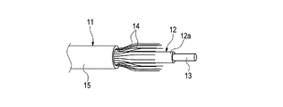
図1に示すように、一対の光ケーブル11は、その光ファイバ心線12から露出されたガラスファイバ13同士が熱融着されて接続され、この接続箇所Aを含む接続部Bが補強されている。
この補強部材21は、平面部22に光ファイバ心線12の部分が配置され、両端側の凹んだケーブル保持部24に光ケーブル11の外被15が配置されている。
なお、上記の例と同一構成部分は、同一符号を付して説明を省略する。
図4に示すように、変形例1における接続部の補強構造では、補強チューブ31によって覆った接続部Bの周囲に保護チューブ51が被せられて熱収縮されて一体化されている。この保護チューブ51は、例えば、電子線架橋軟質ポリオレフィン樹脂からなる耐候性を有するチューブを用いることが好ましい。
図5に示すように、変形例2における接続部の補強構造では、それぞれの光ケーブル11の外被15から露出された抗張力繊維14が、光ファイバ心線12の延出方向へ沿わされ、この抗張力繊維14とともに接続部Bが補強チューブ31によって覆われて一体化されている。
なお、この構造の場合、抗張力繊維14は、露出されたガラスファイバ13に掛からない長さとするのが好ましく、このようにすると抗張力繊維14のガラスファイバ13への接触による不都合がなく、接続部Bを補強することができる。
図6に示すように、変形例3における接続部の補強構造では、融着接続されたガラスファイバ13の部分に、光ファイバ心線12の被覆12aに両端がかかるように、内側チューブ60が被せられている。この内側チューブ60は、熱硬化性樹脂からなるものであり、加熱されることにより収縮されている。また、この内側チューブ60も、透明な樹脂から形成することにより、接続箇所Aの接続状態を目視によって確認することができる。
図7に示すように、変形例4における接続部の補強構造では、変形例3と同様に、ガラスファイバ13の部分が内部補強部材61とともに内側チューブ60によって覆われて一体化されている。また、この変形例4では、それぞれの光ケーブル11の外被15から露出された抗張力繊維14が、光ファイバ心線12の延出方向へ沿わされ、この抗張力繊維14とともに接続部Bが補強チューブ31によって覆われて一体化されている。
この変形例4では、ガラスファイバ13部分が内側チューブ60によって覆われているので、抗張力繊維14のガラスファイバ13への接触による不都合がなく、接続部Bを補強することができる。なお、充分に強度を確保することができれば、補強部材21は無くても良い。
Claims (3)
- 光ファイバ心線の周囲に長手方向へわたって抗張力繊維が沿わされ、その外周が外被によって覆われた一対の光ケーブル同士の接続部の補強構造であって、
前記光ケーブルの前記外被から前記光ファイバ心線が延出され、
前記光ファイバ心線の被覆から露出されたガラスファイバ同士が互いに接続され、
前記光ファイバ心線が配置される部分と、その部分の両端において前記外被が配置されるケーブル保持部との間に段差を有する補強部材が、前記ガラスファイバ同士の接続箇所を含む接続部に沿わされて配設され、
前記補強部材が配設された前記接続部が、それぞれの前記光ケーブルの前記外被に両端がかかるように被せられて収縮された補強チューブによって、前記外被から露出された抗張力繊維とともに覆われて一体化され、
前記外被から露出された前記抗張力繊維が、前記光ファイバ心線の延出方向と逆方向へ折り返され、この折り返し部分が前記補強チューブによって覆われていることを特徴とする接続部の補強構造。 - 請求項1に記載の接続部の補強構造であって、
互いに接続された前記ガラスファイバ部分が、前記光ファイバ心線の被覆に両端がかかるように被せられて収縮された内側チューブによって覆われていることを特徴とする接続部の補強構造。 - 請求項1または2に記載の接続部の補強構造であって、
前記接続部における前記補強チューブの外周が保護チューブによって覆われていることを特徴とする接続部の補強構造。
Priority Applications (9)
| Application Number | Priority Date | Filing Date | Title |
|---|---|---|---|
| JP2009240096A JP5163621B2 (ja) | 2009-10-19 | 2009-10-19 | 接続部の補強構造 |
| US13/501,728 US8641300B2 (en) | 2009-10-19 | 2010-10-01 | Spliced optical cable assembly |
| CN201080046376.6A CN102576129B (zh) | 2009-10-19 | 2010-10-01 | 相连光缆 |
| EP10824775.0A EP2492728A4 (en) | 2009-10-19 | 2010-10-01 | FIBER OPTIC CABLE CONNECTION STRUCTURE |
| IN3280DEN2012 IN2012DN03280A (ja) | 2009-10-19 | 2010-10-01 | |
| KR1020127010089A KR20120091094A (ko) | 2009-10-19 | 2010-10-01 | 광케이블 접속체 |
| CA2777918A CA2777918A1 (en) | 2009-10-19 | 2010-10-01 | Connected optical cable |
| BR112012008634A BR112012008634A2 (pt) | 2009-10-19 | 2010-10-01 | cabo ótico conectado |
| PCT/JP2010/067197 WO2011048926A1 (ja) | 2009-10-19 | 2010-10-01 | 光ケーブル接続体 |
Applications Claiming Priority (1)
| Application Number | Priority Date | Filing Date | Title |
|---|---|---|---|
| JP2009240096A JP5163621B2 (ja) | 2009-10-19 | 2009-10-19 | 接続部の補強構造 |
Publications (3)
| Publication Number | Publication Date |
|---|---|
| JP2011085833A JP2011085833A (ja) | 2011-04-28 |
| JP2011085833A5 JP2011085833A5 (ja) | 2012-11-22 |
| JP5163621B2 true JP5163621B2 (ja) | 2013-03-13 |
Family
ID=43900161
Family Applications (1)
| Application Number | Title | Priority Date | Filing Date |
|---|---|---|---|
| JP2009240096A Active JP5163621B2 (ja) | 2009-10-19 | 2009-10-19 | 接続部の補強構造 |
Country Status (9)
| Country | Link |
|---|---|
| US (1) | US8641300B2 (ja) |
| EP (1) | EP2492728A4 (ja) |
| JP (1) | JP5163621B2 (ja) |
| KR (1) | KR20120091094A (ja) |
| CN (1) | CN102576129B (ja) |
| BR (1) | BR112012008634A2 (ja) |
| CA (1) | CA2777918A1 (ja) |
| IN (1) | IN2012DN03280A (ja) |
| WO (1) | WO2011048926A1 (ja) |
Families Citing this family (3)
| Publication number | Priority date | Publication date | Assignee | Title |
|---|---|---|---|---|
| WO2013153734A1 (ja) | 2012-04-09 | 2013-10-17 | パナソニック株式会社 | ファイバー部品及びレーザ装置 |
| US10209447B2 (en) | 2015-09-11 | 2019-02-19 | Ii-Vi Incorporated | Micro splice protector |
| WO2023227384A1 (en) * | 2022-05-26 | 2023-11-30 | Emtelle Uk Limited | Accessory for protecting spliced optical fibres, optical fibre cable assemblies, kits of parts, methods of manufacture and installation thereof |
Family Cites Families (14)
| Publication number | Priority date | Publication date | Assignee | Title |
|---|---|---|---|---|
| JPS5579307U (ja) * | 1978-11-27 | 1980-05-31 | ||
| FR2519149B1 (fr) * | 1981-12-30 | 1985-07-26 | Cables De Lyon Geoffroy Delore | Dispositif de jonction des extremites de deux cables sous-marins a fibres optiques et son procede de fabrication |
| JPS58156911A (ja) * | 1982-03-12 | 1983-09-19 | Nippon Telegr & Teleph Corp <Ntt> | 光フアイバコ−ドの接続方法 |
| JPS59176013U (ja) * | 1983-05-12 | 1984-11-24 | 日本電気株式会社 | 光フアイバ接続部構造 |
| JPS6463907A (en) * | 1987-05-12 | 1989-03-09 | Furukawa Electric Co Ltd | Reinforcing method for optical coupler |
| JPH09230159A (ja) * | 1996-02-28 | 1997-09-05 | Yazaki Corp | 光ファイバ接続用チューブ構造 |
| US5894536A (en) * | 1997-02-14 | 1999-04-13 | Amphenol Corporation | In-line fiber optic splice protective device |
| JP4257836B2 (ja) * | 2003-05-29 | 2009-04-22 | 株式会社フジクラ | 光ファイバコードの融着接続部補強構造および補強方法 |
| JP4120957B2 (ja) * | 2003-08-29 | 2008-07-16 | 株式会社フジクラ | 光ファイバコードの融着接続部補強構造および補強方法 |
| US7393148B2 (en) * | 2005-12-06 | 2008-07-01 | Tyco Electronics Corporation | Optical fiber splicing closures and methods |
| JP4981521B2 (ja) | 2006-06-28 | 2012-07-25 | 中部電力株式会社 | 補強スリーブ構造体および融着接続部の補強方法 |
| JP5079287B2 (ja) | 2006-09-08 | 2012-11-21 | 株式会社フジクラ | 短余長融着接続部収容部材 |
| US7955004B2 (en) * | 2008-09-04 | 2011-06-07 | Fibersource, Inc. | Fiber optic furcation method |
| WO2011130642A2 (en) * | 2010-04-16 | 2011-10-20 | Adc Telecommunications, Inc. | Fiber optic cable assembly and method of making the same |
-
2009
- 2009-10-19 JP JP2009240096A patent/JP5163621B2/ja active Active
-
2010
- 2010-10-01 EP EP10824775.0A patent/EP2492728A4/en not_active Withdrawn
- 2010-10-01 WO PCT/JP2010/067197 patent/WO2011048926A1/ja active Application Filing
- 2010-10-01 CN CN201080046376.6A patent/CN102576129B/zh active Active
- 2010-10-01 BR BR112012008634A patent/BR112012008634A2/pt not_active IP Right Cessation
- 2010-10-01 IN IN3280DEN2012 patent/IN2012DN03280A/en unknown
- 2010-10-01 US US13/501,728 patent/US8641300B2/en active Active
- 2010-10-01 KR KR1020127010089A patent/KR20120091094A/ko active IP Right Grant
- 2010-10-01 CA CA2777918A patent/CA2777918A1/en not_active Abandoned
Also Published As
| Publication number | Publication date |
|---|---|
| US20120201500A1 (en) | 2012-08-09 |
| IN2012DN03280A (ja) | 2015-10-23 |
| KR20120091094A (ko) | 2012-08-17 |
| EP2492728A4 (en) | 2015-04-08 |
| US8641300B2 (en) | 2014-02-04 |
| BR112012008634A2 (pt) | 2016-04-19 |
| CN102576129B (zh) | 2015-06-17 |
| WO2011048926A1 (ja) | 2011-04-28 |
| CA2777918A1 (en) | 2011-04-28 |
| JP2011085833A (ja) | 2011-04-28 |
| CN102576129A (zh) | 2012-07-11 |
| EP2492728A1 (en) | 2012-08-29 |
Similar Documents
| Publication | Publication Date | Title |
|---|---|---|
| ES2278637T3 (es) | Cable de abonado de fibra optica. | |
| ES2534898T3 (es) | Conector óptico | |
| JP2004518166A (ja) | 光ファイバ保持構造およびその作製方法 | |
| US11327231B2 (en) | Flexible splice protector assembly and method for preparing same | |
| JP5163621B2 (ja) | 接続部の補強構造 | |
| JP2011085833A5 (ja) | ||
| JP4185473B2 (ja) | 光ファイバコード | |
| JP2003322727A (ja) | コネクタ付きケーブルおよび通線方法 | |
| JPWO2005091037A1 (ja) | 光ファイバコード | |
| JPS61162013A (ja) | 光フアイバ端末部補強法 | |
| JP5879620B2 (ja) | 光接続箱 | |
| JP4155570B2 (ja) | 光ファイバコードの融着接続部補強構造および補強方法 | |
| KR100752856B1 (ko) | 방수스틸테이프를 구비하는 광섬유케이블 | |
| JP4981521B2 (ja) | 補強スリーブ構造体および融着接続部の補強方法 | |
| JP4388006B2 (ja) | 光ケーブル | |
| JP7155617B2 (ja) | 光ファイバケーブル | |
| JP3779895B2 (ja) | インドア光ファイバケーブル | |
| JPS60185907A (ja) | 光フアイバ保護部材 | |
| JP2005128326A (ja) | 光ファイバケーブル | |
| JPH0132004Y2 (ja) | ||
| JP2004354732A (ja) | 光ファイバコードの融着接続部補強構造および補強方法 | |
| JP2004212912A (ja) | 光ファイバケーブル接続用スペーサ、光ファイバケーブル接続用クロージャ、及び光ファイバケーブルの接続方法 | |
| JPH0980276A (ja) | 光ファイバコード | |
| JP2004085704A (ja) | 光ファイバコードの分岐補強部 | |
| JP2005043405A (ja) | 分岐用光ファイバ |
Legal Events
| Date | Code | Title | Description |
|---|---|---|---|
| A521 | Request for written amendment filed |
Free format text: JAPANESE INTERMEDIATE CODE: A523 Effective date: 20121005 |
|
| A621 | Written request for application examination |
Free format text: JAPANESE INTERMEDIATE CODE: A621 Effective date: 20121005 |
|
| RD02 | Notification of acceptance of power of attorney |
Free format text: JAPANESE INTERMEDIATE CODE: A7422 Effective date: 20121005 |
|
| TRDD | Decision of grant or rejection written | ||
| A01 | Written decision to grant a patent or to grant a registration (utility model) |
Free format text: JAPANESE INTERMEDIATE CODE: A01 Effective date: 20121120 |
|
| A61 | First payment of annual fees (during grant procedure) |
Free format text: JAPANESE INTERMEDIATE CODE: A61 Effective date: 20121203 |
|
| FPAY | Renewal fee payment (event date is renewal date of database) |
Free format text: PAYMENT UNTIL: 20151228 Year of fee payment: 3 |
|
| R150 | Certificate of patent or registration of utility model |
Ref document number: 5163621 Country of ref document: JP Free format text: JAPANESE INTERMEDIATE CODE: R150 Free format text: JAPANESE INTERMEDIATE CODE: R150 |
|
| R250 | Receipt of annual fees |
Free format text: JAPANESE INTERMEDIATE CODE: R250 |
|
| R250 | Receipt of annual fees |
Free format text: JAPANESE INTERMEDIATE CODE: R250 |
|
| R250 | Receipt of annual fees |
Free format text: JAPANESE INTERMEDIATE CODE: R250 |
|
| R250 | Receipt of annual fees |
Free format text: JAPANESE INTERMEDIATE CODE: R250 |
|
| R250 | Receipt of annual fees |
Free format text: JAPANESE INTERMEDIATE CODE: R250 |
|
| R250 | Receipt of annual fees |
Free format text: JAPANESE INTERMEDIATE CODE: R250 |
|
| R250 | Receipt of annual fees |
Free format text: JAPANESE INTERMEDIATE CODE: R250 |
|
| R250 | Receipt of annual fees |
Free format text: JAPANESE INTERMEDIATE CODE: R250 |
|
| R250 | Receipt of annual fees |
Free format text: JAPANESE INTERMEDIATE CODE: R250 |