JP5149207B2 - Board mounting device - Google Patents
Board mounting device Download PDFInfo
- Publication number
- JP5149207B2 JP5149207B2 JP2009004679A JP2009004679A JP5149207B2 JP 5149207 B2 JP5149207 B2 JP 5149207B2 JP 2009004679 A JP2009004679 A JP 2009004679A JP 2009004679 A JP2009004679 A JP 2009004679A JP 5149207 B2 JP5149207 B2 JP 5149207B2
- Authority
- JP
- Japan
- Prior art keywords
- substrate
- tray
- frame
- clamp
- holding
- Prior art date
- Legal status (The legal status is an assumption and is not a legal conclusion. Google has not performed a legal analysis and makes no representation as to the accuracy of the status listed.)
- Active
Links
- 239000000758 substrate Substances 0.000 claims description 647
- 230000007246 mechanism Effects 0.000 claims description 145
- 238000007689 inspection Methods 0.000 claims description 81
- 238000012546 transfer Methods 0.000 claims description 49
- 238000004519 manufacturing process Methods 0.000 claims description 30
- 238000003780 insertion Methods 0.000 claims description 26
- 230000037431 insertion Effects 0.000 claims description 26
- 239000004065 semiconductor Substances 0.000 claims description 23
- 238000012360 testing method Methods 0.000 claims description 4
- 230000000630 rising effect Effects 0.000 claims description 3
- 238000000034 method Methods 0.000 description 52
- 238000010894 electron beam technology Methods 0.000 description 19
- 230000008569 process Effects 0.000 description 19
- 238000012545 processing Methods 0.000 description 15
- 230000033001 locomotion Effects 0.000 description 14
- 239000002245 particle Substances 0.000 description 10
- 230000007547 defect Effects 0.000 description 9
- 238000001514 detection method Methods 0.000 description 9
- 230000006870 function Effects 0.000 description 9
- 230000008901 benefit Effects 0.000 description 6
- 238000005516 engineering process Methods 0.000 description 6
- 230000001678 irradiating effect Effects 0.000 description 6
- 230000003287 optical effect Effects 0.000 description 6
- 239000010409 thin film Substances 0.000 description 6
- 230000008030 elimination Effects 0.000 description 5
- 238000003379 elimination reaction Methods 0.000 description 5
- 230000003068 static effect Effects 0.000 description 5
- 230000032258 transport Effects 0.000 description 5
- 239000010408 film Substances 0.000 description 4
- 238000013507 mapping Methods 0.000 description 4
- 230000002093 peripheral effect Effects 0.000 description 4
- 238000006243 chemical reaction Methods 0.000 description 3
- 238000010586 diagram Methods 0.000 description 3
- 230000003028 elevating effect Effects 0.000 description 3
- -1 for example Substances 0.000 description 3
- 239000000463 material Substances 0.000 description 3
- 238000006386 neutralization reaction Methods 0.000 description 3
- 238000003825 pressing Methods 0.000 description 3
- 240000006829 Ficus sundaica Species 0.000 description 2
- 230000009471 action Effects 0.000 description 2
- 238000005452 bending Methods 0.000 description 2
- 239000000919 ceramic Substances 0.000 description 2
- 239000011248 coating agent Substances 0.000 description 2
- 238000000576 coating method Methods 0.000 description 2
- 238000007796 conventional method Methods 0.000 description 2
- 238000005520 cutting process Methods 0.000 description 2
- 239000011521 glass Substances 0.000 description 2
- 238000001459 lithography Methods 0.000 description 2
- 238000005192 partition Methods 0.000 description 2
- 229920002493 poly(chlorotrifluoroethylene) Polymers 0.000 description 2
- 239000005023 polychlorotrifluoroethylene (PCTFE) polymer Substances 0.000 description 2
- 238000002360 preparation method Methods 0.000 description 2
- 230000007261 regionalization Effects 0.000 description 2
- RYGMFSIKBFXOCR-UHFFFAOYSA-N Copper Chemical compound [Cu] RYGMFSIKBFXOCR-UHFFFAOYSA-N 0.000 description 1
- 238000000137 annealing Methods 0.000 description 1
- 239000004020 conductor Substances 0.000 description 1
- 229910052802 copper Inorganic materials 0.000 description 1
- 239000010949 copper Substances 0.000 description 1
- 238000011161 development Methods 0.000 description 1
- 230000018109 developmental process Effects 0.000 description 1
- 238000009792 diffusion process Methods 0.000 description 1
- 238000001312 dry etching Methods 0.000 description 1
- 238000005530 etching Methods 0.000 description 1
- 238000007667 floating Methods 0.000 description 1
- 238000003384 imaging method Methods 0.000 description 1
- 238000002513 implantation Methods 0.000 description 1
- 239000012535 impurity Substances 0.000 description 1
- 239000012212 insulator Substances 0.000 description 1
- 238000011068 loading method Methods 0.000 description 1
- 238000005259 measurement Methods 0.000 description 1
- 230000015654 memory Effects 0.000 description 1
- 239000002184 metal Substances 0.000 description 1
- 229910052751 metal Inorganic materials 0.000 description 1
- 230000003647 oxidation Effects 0.000 description 1
- 238000007254 oxidation reaction Methods 0.000 description 1
- 230000001590 oxidative effect Effects 0.000 description 1
- 230000000452 restraining effect Effects 0.000 description 1
- 238000004544 sputter deposition Methods 0.000 description 1
- 230000000087 stabilizing effect Effects 0.000 description 1
- 239000000126 substance Substances 0.000 description 1
Images


Landscapes
- Container, Conveyance, Adherence, Positioning, Of Wafer (AREA)
Description
本発明は、基板をトレーへ搭載する基板搭載装置に関し、特に、トレーに対する基板の位置決め技術に関する。 The present invention relates to a substrate mounting apparatus for mounting a substrate on a tray, and more particularly to a technique for positioning a substrate with respect to a tray.
半導体製造分野に関わる基板として、例えば、マスク及びウエハが挙げられる。半導体の製造過程では、基板の異物、欠陥等の高精度な検査が必要である。マスク検査の場合、従来一般には光学式検査装置が用いられていた。しかし、最近はマスク上のパターンが微細化し、検出すべき欠陥や異物も微細化している。例えば、マスクのパターンサイズが60nmレベルに達し、検出すべき欠陥及び異物のサイズも5〜20nmレベルに達している。こうした微細化の要求に応えるため、マスク検査に電子ビームを用いることが提案されている。電子ビーム式の検査装置としては、SEM式の検査装置及び写像投影型の検査装置が知られている。写像投影型の検査装置は、比較的大きいサイズの電子ビームをマスクに照射し、基板から得られる信号から基板の画像を生成する。 Examples of the substrate related to the semiconductor manufacturing field include a mask and a wafer. In the process of manufacturing semiconductors, high-precision inspection of foreign substances and defects on the substrate is necessary. In the case of mask inspection, an optical inspection apparatus has been generally used. However, recently, the pattern on the mask is miniaturized, and defects and foreign matters to be detected are also miniaturized. For example, the mask pattern size reaches the 60 nm level, and the size of the defect and foreign matter to be detected also reaches the 5 to 20 nm level. In order to meet the demand for such miniaturization, it has been proposed to use an electron beam for mask inspection. As an electron beam type inspection apparatus, an SEM type inspection apparatus and a mapping projection type inspection apparatus are known. The projection type inspection apparatus irradiates a mask with an electron beam having a relatively large size, and generates an image of the substrate from a signal obtained from the substrate.
マスク等の基板は、トレーに搭載されることがある。トレーを用いることにより、搬送過程や各種装置へのセット時の基板の扱いが容易になる。例えば、特許文献1は、露光装置用のマスクトレーを開示している。また例えば、特許文献2は、成膜装置用のマスクトレーを開示している。本明細書では、基板をトレーに搭載する装置を、基板搭載装置という。 A substrate such as a mask may be mounted on a tray. Use of the tray facilitates handling of the substrate during the transfer process and setting in various apparatuses. For example, Patent Document 1 discloses a mask tray for an exposure apparatus. Further, for example, Patent Document 2 discloses a mask tray for a film forming apparatus. In this specification, an apparatus for mounting a substrate on a tray is referred to as a substrate mounting apparatus.
また、半導体製造分野では、マスク等の基板を適正位置に位置決めすることが重要である。特許文献3は、露光前のマスクを位置決めする技術を開示しており、この従来技術は、マスク上のマークの検出結果に基づいてマスクステージを移動する。また、特許文献4もマスクの位置決め技術を開示しており、この従来技術は、マスクの一端を位置決めピンで支持し、他端を押圧ピンで押圧する。 In the semiconductor manufacturing field, it is important to position a substrate such as a mask at an appropriate position. Patent Document 3 discloses a technique for positioning a mask before exposure, and this conventional technique moves a mask stage based on a detection result of a mark on the mask. Patent Document 4 also discloses a mask positioning technique. This conventional technique supports one end of a mask with a positioning pin and presses the other end with a pressing pin.
基板のトレーを用いる場合にも位置決めは重要である。従来は、基板をトレーに位置決めするために、トレーの基板収容部にテーパ面が設けられている。そして、基板外周縁がテーパ面に接することにより、基板が基板収容部の中央に位置決めされる。
しかしながら、テーパ構造で基板を位置決めする場合、基板外周部の状態や、トレーのテーパ部の状態により、基板が斜めに配置されてしまうことがある。例えば、基板外周の凹凸形状や膜が、基板を傾斜させる原因になる。 However, when the substrate is positioned with the taper structure, the substrate may be disposed obliquely depending on the state of the outer peripheral portion of the substrate and the state of the taper portion of the tray. For example, uneven shapes and films on the outer periphery of the substrate cause the substrate to be inclined.
トレー上での基板の位置精度は、後段の処理等の精度に影響する。例えば、トレーへの基板の位置決めが「仮の位置決め」であり、それから「本位置決め」が行われることがある。本位置決めでは、基板上のマークがCCDカメラで撮影され、マーク位置に基づいてトレイ位置が制御される。しかし、テーパ構造を用いる場合、トレーでの基板位置の精度が低く、そのためにマーク位置のばらつきが大きく、CCDカメラの視野を広げる必要がある。視野の拡大は、撮像倍率を低下させ、本位置決めの精度を低下させる要因になる。例えば、トレーがマスク検査装置で用いられる場合、マスクの検査精度が低下する可能性がある。 The positional accuracy of the substrate on the tray affects the accuracy of subsequent processing and the like. For example, the positioning of the substrate to the tray may be “temporary positioning” and then “main positioning” may be performed. In this positioning, the mark on the substrate is photographed by the CCD camera, and the tray position is controlled based on the mark position. However, when the taper structure is used, the accuracy of the substrate position on the tray is low, so that the variation of the mark position is large, and it is necessary to widen the field of view of the CCD camera. The enlargement of the field of view reduces the imaging magnification and causes a decrease in the accuracy of the main positioning. For example, when a tray is used in a mask inspection apparatus, the mask inspection accuracy may be reduced.
また、マスク検査の場合、マスクの両面を順次検査することがある。この場合、検査過程を通じてマスクの両面への接触を極力避ける必要がある。したがって、トレーへの基板の搭載も、マスクの位置決めも、マスクになるべく接することなく高精度に行うことが求められる。 In the case of mask inspection, both sides of the mask may be inspected sequentially. In this case, it is necessary to avoid contact with both sides of the mask as much as possible throughout the inspection process. Therefore, it is required to mount the substrate on the tray and position the mask with high accuracy without touching the mask as much as possible.
また、マスク検査では、マスクの上側表面に電位を付与することがある。表面電位は極力均一にすることが求められる。そして、上面への電位付与の構成を設けた場合でも、位置決めを適切に行うことが求められる。 In mask inspection, a potential may be applied to the upper surface of the mask. The surface potential is required to be as uniform as possible. Even when a configuration for applying a potential to the upper surface is provided, it is required to perform positioning appropriately.
以上、本発明の背景技術について、マスクとその検査技術を取り上げて説明した。しかし、上記の背景技術は、マスク以外の基板にも当てはまり、検査以外のケースにも当てはまり得る。 The background technology of the present invention has been described above by taking the mask and its inspection technology. However, the above background art applies to substrates other than masks, and may apply to cases other than inspection.
本発明は上記背景に鑑みてなされたものであり、その目的は、基板の斜め配置を防止でき、トレーに対して基板を高精度に位置決めできる基板搭載技術を提供することにある。 The present invention has been made in view of the above-described background, and an object of the present invention is to provide a substrate mounting technology that can prevent the oblique arrangement of the substrates and can position the substrate with respect to the tray with high accuracy.
本発明の一の目的は、基板になるべく接触せずに、位置決めを好適に行える基板搭載技術を提供することにある。 An object of the present invention is to provide a substrate mounting technique that can suitably perform positioning without contacting the substrate as much as possible.
本発明の一の目的は、基板上面に電位を付与する場合でも位置決めを好適に行える基板搭載技術を提供することにある。 An object of the present invention is to provide a substrate mounting technique that can perform positioning appropriately even when a potential is applied to the upper surface of a substrate.
本発明の一態様は、基板を保持するトレーへと基板を搭載する基板搭載装置であって、トレーを保持するステージと、トレーに対して前記基板を位置決めするクランプ機構とを備え、クランプ機構は、基板平面に平行に移動可能な複数のクランプ体を有し、複数のクランプ体の各々が、トレーに当接するトレークランプ部と、基板に当接する基板クランプ部とを有し、複数のクランプ体が一度のクランプ動作にてトレー及び基板の両方をクランプすることにより、クランプ体のトレークランプ部と基板クランプ部の位置関係に対応してトレーに対して基板を位置決めする。 One aspect of the present invention is a substrate mounting apparatus that mounts a substrate on a tray that holds a substrate, and includes a stage that holds the tray, and a clamp mechanism that positions the substrate with respect to the tray. A plurality of clamp bodies movable parallel to the substrate plane, each of the plurality of clamp bodies having a tray clamp portion that contacts the tray and a substrate clamp portion that contacts the substrate, and the plurality of clamp bodies However, by clamping both the tray and the substrate by a single clamping operation, the substrate is positioned relative to the tray in accordance with the positional relationship between the tray clamp portion and the substrate clamp portion of the clamp body.
上記のように、本発明によれば、クランプ機構がトレー及び基板の両方を一度のクランプ動作でクランプする。このクランプ動作は、複数のクランプ片で異なる方向からトレー及び基板を押圧する動作である。基板平面に平行に移動するクランプ機構を用いるので、基板を傾斜させることなく位置決めできる。また、トレークランプ部と基板クランプ部を一体に備えたクランプ体でトレーと基板を一度にクランプするので、トレークランプ部と基板クランプ部の位置関係に応じてトレー対して基板が位置決めされ、トレーと基板の位置関係が正確に定まる。したがって、トレーに対して基板を高精度に位置決めできる。 As described above, according to the present invention, the clamping mechanism clamps both the tray and the substrate with a single clamping operation. This clamping operation is an operation of pressing the tray and the substrate from different directions with a plurality of clamp pieces. Since a clamp mechanism that moves parallel to the substrate plane is used, the substrate can be positioned without being inclined. In addition, since the tray and the substrate are clamped at a time with the clamp body integrally provided with the tray clamp portion and the substrate clamp portion, the substrate is positioned with respect to the tray according to the positional relationship between the tray clamp portion and the substrate clamp portion. The positional relationship of the substrates is accurately determined. Therefore, the substrate can be positioned with high accuracy with respect to the tray.
また、本発明によれば、上述のように基板とトレーを一度の動作でクランプするので、基板だけでなくトレーの位置決めも同時に行えるという利点も得られる。 Further, according to the present invention, since the substrate and the tray are clamped by one operation as described above, there is an advantage that not only the substrate but also the tray can be positioned at the same time.
また、本発明によれば、クランプで基板に接するので、基板への接触をなるべく避けられる。位置決め完了後にクランプを解除することが好適であり、接触時間を低減できる。したがって、本発明によれば、基板になるべく接触せずに、位置決めを好適に行うことができる。 In addition, according to the present invention, the clamp contacts the substrate, so that contact with the substrate is avoided as much as possible. It is preferable to release the clamp after the positioning is completed, and the contact time can be reduced. Therefore, according to the present invention, positioning can be suitably performed without contacting the substrate as much as possible.
本発明の別の態様は、基板を保持するトレーへと基板を搭載する基板搭載方法であって、トレーをステージに保持し、トレーに保持されるべき基板を用意し、トレーに対して基板をクランプ機構を用いて位置決めし、位置決め工程では、クランプ機構が基板及びトレーの両方に当接することにより、一度のクランプ動作でトレー及び基板の両方をクランプし、トレーに接する部位と基板に接する部位の位置関係に対応してトレーに対して基板を位置決めする。 Another aspect of the present invention is a substrate mounting method for mounting a substrate on a tray that holds a substrate, the tray being held on a stage, a substrate to be held on the tray being prepared, and the substrate being mounted on the tray In the positioning process, the clamp mechanism abuts both the substrate and the tray, so that both the tray and the substrate are clamped by a single clamping operation. The substrate is positioned with respect to the tray corresponding to the positional relationship.
本発明の別の態様は、上記の基板搭載装置により基板を搭載されるトレーであって、トレー本体と、トレー本体から突出し、基板がトレー本体に非接触の状態で基板の下面を支持する複数の基板搭載ピンと、複数の基板搭載ピンに支持された基板を取り囲むように設けられ、かつ、トレー本体から上昇可能に設けられた額縁とを備える。基板表面に平行な方向に一度のクランプ動作でトレー本体と基板の両方がクランプされることにより、クランプ機構のトレー本体に接する部位と基板に接する部位の位置関係に対応して基板がトレーに対して位置決めされてよい。 Another aspect of the present invention is a tray on which a substrate is mounted by the above-described substrate mounting apparatus, and a plurality of trays that protrude from the tray body and support the lower surface of the substrate without contacting the tray body. And a frame provided so as to surround the substrate supported by the plurality of substrate mounting pins and capable of being raised from the tray body. By clamping both the tray body and the substrate in a direction parallel to the substrate surface by a single clamping operation, the substrate moves relative to the tray according to the positional relationship between the portion contacting the tray body and the portion contacting the substrate of the clamping mechanism. May be positioned.
本発明の別の態様は、上記の基板搭載装置又は方法を用いてトレーに搭載された基板に荷電粒子ビームを照射して基板を検査する基板検査装置又は方法である。
本発明の別の態様は、上記の基板搭載装置又は方法を用いてトレーに搭載された基板に荷電粒子ビームを照射して、基板製作工程の検査を行う基板製造装置又は方法である。
本発明の別の態様は、上記の基板検査装置又は方法により検査された基板、又は、上記の基板製造装置又は方法により製造された基板である。
本発明の別の態様は、上記の基板を用いて半導体装置を製造する半導体製造装置又は方法である。
本発明の別の態様は、上記の基板を用いて製造された半導体装置、又は、上記の半導体製造装置又は方法により製造された半導体装置である。
本発明の別の態様は、上記の基板搭載装置又は方法を用いてトレーに搭載されたマスクに荷電粒子ビームを照射してマスクを検査するマスク検査装置又は方法である。
本発明の別の態様は、上記の基板搭載装置又は方法を用いてトレーに搭載されたマスクに荷電粒子ビームを照射して、マスク製作工程の検査を行うマスク製造装置又は方法である。
本発明の別の態様は、上記のマスク検査装置又は方法により検査されたマスク、又は、上記のマスク製造装置又は方法により製造されたマスクである。
本発明の別の態様は、上記のマスクを用いて半導体装置を製造する半導体製造装置又は方法である。
本発明の別の態様は、上記のマスクを用いて製造された半導体装置、又は、上記の半導体製造装置又は方法により製造された半導体装置である。
Another aspect of the present invention is a substrate inspection apparatus or method for inspecting a substrate by irradiating a charged particle beam onto a substrate mounted on a tray using the substrate mounting apparatus or method described above.
Another aspect of the present invention is a substrate manufacturing apparatus or method for inspecting a substrate manufacturing process by irradiating a substrate mounted on a tray with a charged particle beam using the substrate mounting apparatus or method described above.
Another aspect of the present invention is a substrate inspected by the above substrate inspection apparatus or method, or a substrate manufactured by the above substrate manufacturing apparatus or method.
Another aspect of the present invention is a semiconductor manufacturing apparatus or method for manufacturing a semiconductor device using the substrate described above.
Another embodiment of the present invention is a semiconductor device manufactured using the above substrate, or a semiconductor device manufactured by the above semiconductor manufacturing device or method.
Another aspect of the present invention is a mask inspection apparatus or method for inspecting a mask by irradiating a mask mounted on a tray with a charged particle beam using the substrate mounting apparatus or method described above.
Another aspect of the present invention is a mask manufacturing apparatus or method for inspecting a mask manufacturing process by irradiating a mask mounted on a tray with a charged particle beam using the substrate mounting apparatus or method described above.
Another aspect of the present invention is a mask inspected by the above mask inspection apparatus or method, or a mask manufactured by the above mask manufacturing apparatus or method.
Another aspect of the present invention is a semiconductor manufacturing apparatus or method for manufacturing a semiconductor device using the mask.
Another embodiment of the present invention is a semiconductor device manufactured using the above mask, or a semiconductor device manufactured by the above semiconductor manufacturing apparatus or method.
上記のように、本発明は、基板の斜め配置を防止でき、トレーに対して基板を高精度に位置決めできる基板搭載技術を提供できる。また、本発明は、基板になるべく接触せずに、位置決めを好適に行える基板搭載技術を提供できる。また、本発明は、基板上面に電位を付与する場合でも位置決めを好適に行える基板搭載技術を提供できる。 As described above, the present invention can provide a substrate mounting technique that can prevent the substrate from being obliquely arranged and can position the substrate with respect to the tray with high accuracy. In addition, the present invention can provide a substrate mounting technology that can suitably perform positioning without contacting the substrate as much as possible. In addition, the present invention can provide a substrate mounting technique capable of suitably positioning even when a potential is applied to the upper surface of the substrate.
以下、本発明の実施の形態の基板搭載装置について、図面を用いて説明する。 Hereinafter, a substrate mounting apparatus according to an embodiment of the present invention will be described with reference to the drawings.
本実施の形態では、基板が、例えば、EUV露光装置で使用されるマスクである。そして、基板搭載装置が、例えば、マスク用の基板検査装置に備えられる。 In the present embodiment, the substrate is a mask used in an EUV exposure apparatus, for example. Then, the substrate mounting apparatus is provided in a substrate inspection apparatus for a mask, for example.
図1及び図2は、基板搭載装置が備えられた検査装置を示している。基板搭載装置について詳細に説明する前に、検査装置の概要を説明する。 1 and 2 show an inspection apparatus provided with a substrate mounting apparatus. Before describing the substrate mounting apparatus in detail, an outline of the inspection apparatus will be described.
図1は、検査装置1を上方から見た図である。図1に示されるように、検査装置1は、大気搬送部3と真空搬送部5に大きく分けられる。大気搬送部3は基板を大気中で扱い、真空搬送部5は基板を真空中で扱う。大気搬送部3と真空搬送部5は、開閉可能な隔壁で仕切られている。 FIG. 1 is a view of the inspection apparatus 1 as viewed from above. As shown in FIG. 1, the inspection apparatus 1 is roughly divided into an atmospheric transfer unit 3 and a vacuum transfer unit 5. The atmospheric transfer unit 3 handles the substrate in the atmosphere, and the vacuum transfer unit 5 handles the substrate in vacuum. The atmospheric transfer unit 3 and the vacuum transfer unit 5 are partitioned by a partition that can be opened and closed.
大気搬送部3は、ミニエンバイロメント室といわれる。大気搬送部3に隣接してスミフポッド7が設けられている。また大気搬送部3には、大気搬送ロボット9、基板回転反転ユニット11、基板搭載ユニット13、除電ユニット15及びファンフィルタユニット(FFU)が設けられている。
The atmospheric transfer unit 3 is called a mini-environment chamber. A smif pod 7 is provided adjacent to the atmospheric transfer unit 3. The atmospheric transfer unit 3 includes an
スミフポッド7は、検査前後の基板(マスク)を保持する構成である。大気搬送ロボット9は大気中で基板を搬送するロボットである。基板回転反転ユニット11は、大気搬送ロボット9から基板を受け取り、回転及び反転させることができる。基板搭載ユニット13は、トレーに基板を搭載する。基板搭載ユニット13が本実施の形態の基板搭載装置である。除電ユニット15は、検査前後に基板の除電処理を行う。ファンフィルタユニット(FFU)は、図示されないが、大気搬送部3のミニエンバイロメント室内の上部に設けられている。より詳細には、FFUは、大気搬送ロボット9、基板回転反転ユニット11、基板搭載ユニット13、除電ユニット15等の上方であって天井又はその付近に設けられている。
The smif pod 7 is configured to hold a substrate (mask) before and after the inspection. The
また、真空搬送部5にはロードロックチャンバ17、トランスファーチャンバ19、第1ターボ分子ポンプ21、メインチャンバ23、検査鏡筒25及び第2ターボ分子ポンプ27が設けられている。
Further, the vacuum transfer unit 5 is provided with a
ロードロックチャンバ17には、2つのCCDカメラ29が配置されている。CCDカメラ29は後述するように基板の位置決めに用いられる。トランスファーチャンバ19は、ロードロックチャンバ17からメインチャンバ23へ基板を搬送するためのチャンバである。トランスファーチャンバ19には真空搬送ロボット31が備えられている。真空搬送ロボット31は真空内で基板を搬送するロボットである。また、第1ターボ分子ポンプ21は、ロードロックチャンバ17及びトランスファーチャンバ19を真空にする。メインチャンバ23及び検査鏡筒25は、基板に荷電粒子ビームを照射して基板を検査する構成である。第2ターボ分子ポンプ27は、メインチャンバ23及び検査鏡筒25を真空にする。
Two
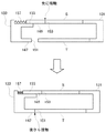
図2は、メインチャンバ23及び検査鏡筒25を横方向から見た図である。メインチャンバ23はステージ33を備える。ステージ33には、基板を保持したトレーが載置される。ステージ33は、トレーを水平方向に移動する構成であり、X、Y、θ方向にトレーを移動する。X、Y方向は互いに直交する軸に沿った方向であり、θは回転軸周りの角度であり、すなわち回転移動も行われる。
FIG. 2 is a view of the
検査鏡筒25は、メインチャンバ23の上側に接続されている。検査鏡筒25は、電子銃35、一次レンズ系37、二次レンズ系39及び検出器41を備える。電子銃35は荷電粒子ビーム源である。電子銃35及び一次レンズ系37は、電子ビーム照射系であり、基板へ電子ビームを照射する。電子ビームは、ウィーンフィルタ43で偏向され、対物レンズ系45を通り、基板に照射される。電子ビームが基板に照射されると、基板は、基板の情報を持つ信号を放出する。信号は、例えば、二次電子、反射電子又はミラー電子である。この信号が、対物レンズ系45、ウィーンフィルタ43、二次レンズ系39を通り、検出器41に到達し、検出器41で検出される。
The
検出器41は、画像処理部47に接続されており、検出された信号を画像処理部47に供給する。画像処理部47は、画像処理機能を持ったコンピュータで構成されており、欠陥検査の処理を行う。すなわち、画像処理部47は、検出器41で検出された信号から試料の像を形成し、さらに、試料の像を処理して欠陥の検出及び判定を行う。
The
また、図2に示されるように、検査装置1は制御部49を備える。制御部49はコンピュータで構成されており、検査装置1の全体を制御して検査を実行する構成である。制御部49は、図示のように、メインチャンバ23、検査鏡筒25及び画像処理部47を制御する。これにより、制御部49は、基板(トレー)を移動させ、基板に電子ビームを照射し、画像処理部47に基板の画像を生成させる。
Further, as shown in FIG. 2, the inspection apparatus 1 includes a
制御部49は、検査条件を制御することができ、具体的には、電子ビームのビームエネルギー、倍率、ドーズ量などを制御する。ビームエネルギーは具体的には基板に電子ビームが照射されるときのランディングエネルギーである。
The
本実施の形態では、検査装置1が、写像投影式の検査装置である。写像投影式の検査装置では、電子ビームが、2次元画素群に対応するビームサイズ(ビーム径)を有しており、つまり、ある程度のサイズを有している。試料上の照射領域も、2次元画素群に応じた面積を有する。検出器41で検出される信号も、2次元画素群に対応する。そして、検出器41は、2次元画素群に対応する検知能力を有し、例えば、2次元の検知面を有するCCDで構成されている。
In the present embodiment, the inspection apparatus 1 is a mapping projection type inspection apparatus. In the projection type inspection apparatus, the electron beam has a beam size (beam diameter) corresponding to the two-dimensional pixel group, that is, has a certain size. The irradiation area on the sample also has an area corresponding to the two-dimensional pixel group. A signal detected by the
写像投影式の検査装置をSEM式の検査装置と比較する。SEMでは電子ビームが細く、1画素に対応する。SEMでは電子ビームが走査されて、1画素の計測が繰り返され、そして、計測値が集積されて、試料の像が得られる。SEM式の検査装置では電子ビームが1画素のビームサイズを有するのに対して、写像投影型の検査装置では電子ビームが複数画素群に対応するビームサイズを有する。写像投影型の検査装置は、微細な欠陥を検査できる。また、写像投影型の検査装置は、パターン欠陥に限られず、複数種類の検査を行うことができる。例えば、写像投影型の検査装置は、パーティクル等の異物検査にも使用可能であり、さらには、多層膜中欠陥検査にも使用可能である。 The projection type inspection apparatus is compared with the SEM type inspection apparatus. In the SEM, the electron beam is thin and corresponds to one pixel. In the SEM, the electron beam is scanned, the measurement of one pixel is repeated, and the measured values are integrated to obtain an image of the sample. In the SEM type inspection apparatus, the electron beam has a beam size of one pixel, whereas in the mapping projection type inspection apparatus, the electron beam has a beam size corresponding to a plurality of pixel groups. The projection type inspection apparatus can inspect fine defects. The projection type inspection apparatus is not limited to pattern defects, and can perform a plurality of types of inspection. For example, a mapping projection type inspection apparatus can be used for inspection of foreign matters such as particles, and can also be used for inspection of defects in multilayer films.
図1に戻り、検査装置1の全体的な動作を説明する。大気搬送ロボット9は、スミフポッド7から基板を取り出して、除電ユニット15に搬送する。除電ユニット15は基板の除電を行う。また、基板は大気搬送ロボット9により基板回転反転ユニット11に搬送され、基板の反転及び回転が必要に応じて行われる。さらに、大気搬送ロボット9が基板を基板搭載ユニット13に搬送する。基板搭載ユニット13では、予め用意されたトレーに基板が搭載される。
Returning to FIG. 1, the overall operation of the inspection apparatus 1 will be described. The
基板がトレーに搭載されると、大気搬送ロボット9は、トレーを保持してロードロックチャンバ17に搬送する。このとき、大気搬送部3と真空搬送部5の隔壁が開かれる。ロードロックチャンバ17では、CCDカメラ29が基板のマークを撮影する。これによりマーク位置が検出される。真空搬送ロボット31は、ロードロックチャンバ17からメインチャンバ23へトレーを搬送し、メインチャンバ23のステージ33にトレーを載置する。このとき、マーク検出結果に基づいて基板が位置決めされる。
When the substrate is mounted on the tray, the
基板は、トレーへ搭載されるときに、基板搭載ユニット13により位置決めされる。そして、更に、上記のようにステージ33へ搭載されるときに、CCDカメラ29の検出結果に基づき基板が位置決めされる。前者の位置決めを「仮位置決め」といい、後者の位置決めを「本位置決め」ということができる。実際の基板検査過程では、本位置決めの後に、光学顕微鏡を用いて更なる位置決めが行われてよい。光学顕微鏡は、電子線検査装置と共にメインチャンバ23に配置される。光学顕微鏡の光学像を用いて基板がトレーと共に位置決めされ、それから電子線を用いて基板が検査される。ここでは、例えば、光学顕微鏡で検出された欠陥位置へ電子線が照射されるように基板が位置決めされる。
The substrate is positioned by the
メインチャンバ23では、図2を用いて説明したように、基板が電子ビーム照射により検査される。検査終了後の基板は、メインチャンバ23からトランスファーチャンバ19を通ってロードロックチャンバ17へと、真空搬送ロボット31により搬送される。
In the
そして、大気搬送ロボット9が、ロードロックチャンバ17から基板搭載ユニット13へと基板を搬送する。基板搭載ユニット13にて基板がトレーから外される。基板は基板回転反転ユニット11に搬送され、必要に応じて回転及び反転される。続いて、基板が除電ユニット15に搬送されて、除電が行われる。そして、基板は大気搬送ロボット9によりスミフポッド7へと戻される。
Then, the
以上に検査装置1の全体的な構成及び動作を説明した。上記構成は典型的なシステム構成例であり、また、上記動作は典型的な動作パターン例である。本発明の範囲で検査装置の構成及び動作は上記の例に限定されない。 The overall configuration and operation of the inspection apparatus 1 have been described above. The above configuration is a typical system configuration example, and the above operation is a typical operation pattern example. The configuration and operation of the inspection apparatus are not limited to the above example within the scope of the present invention.
「基板搭載装置」
次に、本実施の形態の基板搭載装置について詳細に説明する。基板搭載装置は、既に述べたように図1の基板搭載ユニット13に相当し、大気搬送ロボット9と共に機能して基板をトレーに搭載する。基板は、例えばマスクであり、より詳細には、例えば、一辺が6インチの正方形で厚さが6.35mmのガラス製マスクである。
"Board mounting device"
Next, the substrate mounting apparatus of the present embodiment will be described in detail. As described above, the substrate mounting apparatus corresponds to the
図3〜図12は、本実施の形態の基板搭載装置を示している。図3〜図6は、トレー無しの状態の基板搭載装置51を示し、図7〜図10は、トレーと共に基板搭載装置51を示している。図3は基板搭載装置51の平面図であり、図4は、図3の基板搭載装置51を矢印Aの方向から見た図であり、図5は、図3の基板搭載装置51を矢印Bの方向から見た図であり、図6は、図3の基板搭載装置51を矢印C方向から見た図であって、トレーT及び基板Sの対角線に沿って切断した図である。同様に、図7は基板搭載装置51の平面図であり、図8は、図7の基板搭載装置51を矢印Dの方向から見た図であり、図9は、図7の基板搭載装置51を矢印Eの方向から見た図であり、図10は、図7の基板搭載装置51を矢印Fの方向から見た図であって、トレーT及び基板Sの対角線に沿って切断した図である。また、図11及び図12は、説明のために基板搭載装置51を模式的に示す簡略図である。
3 to 12 show the substrate mounting apparatus of the present embodiment. 3 to 6 show the
基板搭載装置51は、トレーTに基板Sを搭載する装置である。基板搭載装置51は、概略的には、ステージ53、リフト機構55、クランプ機構57、トレー保持機構59及び額縁ドロップ機構61で構成される。以下では、まずトレーTの構成を説明し、それから基板搭載装置51の各種構成について説明する。
The
「トレーT」
図7〜図12を参照し、トレーTの構成を説明する。図11等に示されるように、トレーTは、トレー本体71と額縁73とで構成される。トレーTは例えばセラミック製である。
"Tray T"
The configuration of the tray T will be described with reference to FIGS. As shown in FIG. 11 and the like, the tray T includes a
トレー本体71は平板状であり、四角形の基板Sに対応して略四角形の形状を有する。トレー本体71からは複数の基板搭載ピン75が突出しており、基板Sはこれら基板搭載ピン75に支持される。ピン本数は4である。このような構成により、基板Sは、基板搭載ピン75と小さい接触面積で接触し、そして、トレー本体71に直接接触することなく浮いた状態で保持される。また、基板搭載ピン75は、基板Sが滑りにくい表面を有しており、これにより、搬送中の基板Sのずれが防止される。
The
額縁73は、トレー本体71に支持されており、基板Sを取り囲む。額縁73は、検査時に基板Sの上面に電位を付与するための構成であり、端子部77を介して電位を付与する。また、額縁73が基板Sを取り囲むことによりダミーとして機能する。基板Sの端部での等電位面の屈曲が軽減され、端部付近の電位を均一にでき、その結果、端部を含む基板全体の電位を均一にでき、検査精度を向上できる。また、額縁73はトレー本体71に対して昇降可能である。図11に示されるように、下降時は、額縁表面と基板表面が同じ高さにあり、額縁73が基板Sを取り囲む。図8及び図9に示されるように、額縁73が上昇すると、トレー本体71と額縁73の間に、挿入口79が形成される。挿入口79は、トレー本体71と額縁73の間の隙間又は開口であり、挿入隙間といってもよい。挿入口79は、基板Sの挿入及び抜取りを可能にし、また、基板Sへの位置決めのためのアクセスを可能にする。
The
額縁73のより詳細な構成を説明する。額縁73は、額縁本体81と、額縁本体81から下方に延びる複数の額縁脚部83を有する。
A more detailed configuration of the
図7及び図12に示されるように、額縁本体81は、四角形の平板であり、四角形の開口85を有する。額縁本体81の材質は絶縁体でよく、例えばセラミックである。開口85は、基板Sに応じた大きさを有する。基板Sは開口85内に配置され、これにより基板Sが額縁73に取り囲まれる。額縁本体81と基板Sは直接接触しない。額縁本体81と基板Sが全周にわたってほぼ一定の隙間を形成する。
As shown in FIGS. 7 and 12, the
額縁73の上面には額縁カバー86が設置されている。図8を参照すると、額縁73の上端の幅が額縁本体83より少し広く、そして額縁73の上端部分が少し内側に突出しており、この上端部分が額縁カバー86に相当する。図17は額縁カバー86を模式的に示している。図17に示されるように、額縁カバー86は、薄い平板である。額縁カバー86は外側端部にてL字状に下向きに折れ曲がっており、そして、図示のように額縁本体81の側面にねじ等で固定されている(額縁カバー86は額縁本体81の上面等の他の場所に固定されてもよい)。額縁カバー86の材質は導電材であり、例えば銅である。額縁カバー86の外周形状は額縁本体81とほぼ同様である。しかし、額縁カバー86の開口は、額縁本体81の開口85より小さく、したがって、額縁カバー86は額縁本体81よりも内側に突出している。基板Sが搭載されたとき、額縁カバー86の内周縁は、基板Sの外周縁と重なり、接触する。このような重なりが生じるように、額縁カバー86の開口サイズが定められている。したがって、上方から見たときに、額縁カバー86は、額縁73(額縁本体81)と基板Sの隙間をカバーする。このような額縁カバー86を設けることにより、基板Sの縁部における等電位面の屈曲を軽減することができる。額縁カバー86は、図11、図12等の模式図では省略されている。
A
額縁本体81には、2つの端子部77が設けられている。端子部77は、開口85に突出している。そして、基板Sが開口85内に配置されたとき、端子部77が基板Sの上面に接する。上述したように、端子部77は、基板検査時に基板Sの上面に電位を付与するために用いられる。また、上述の額縁カバー86は、これら端子部77を除く額縁全周にて基板Sと額縁73の隙間を覆っている。
The
額縁脚部83の本数は4であり、これら4本の額縁脚部83が、額縁本体81の4隅の近くにそれぞれ配置されている。図11に示されるように、下降時は、額縁脚部83がトレー本体71に支持され、額縁本体81がトレー本体71の上方に位置し、そして、額縁上面が基板搭載ピン75上の基板Sの上面とほぼ同じ高さに位置する(図17に示されるように、詳細には、額縁本体81の上面が基板上面と同じ高さに位置する。額縁カバー86の上面は、基板上面とほぼ同じ高さに位置するが、詳細にはカバー厚さだけ基板上面よりも少し上にある。以下同じ)。額縁73が上昇すると、トレー本体71と額縁本体81の間に挿入口79が形成され、基板Sの出し入れや、基板Sへのアクセスが可能になる。
The number of the
また、図8及び図9に示されるように、額縁73の昇降動作をガイドするために、昇降ガイド87が設けられている。昇降ガイド87は、トレー本体71から突出するガイド棒である。この昇降ガイド87が、額縁脚部83のガイド穴に挿入されている。これにより、額縁73は、トレー平面に対して垂直方向にのみ移動できる。
Further, as shown in FIGS. 8 and 9, an elevating
また、図7等に示されるように、トレー本体71は、複数の突出縁部89を有する。本実施の形態では、4つの突出縁部89が、トレー本体71の4隅にそれぞれ設けられている。突出縁部89は、額縁73よりも外側へ突出する部分である。より詳細には、トレー本体71の各隅に壁部が設けられ、壁部の上端から外側へ突出縁部89が突出している。突出縁部89は、後述するように、搬送ロボットによるトレーTの支持に用いられ、また、額縁73の上昇時にトレー本体71を保持するために用いられる。
Further, as shown in FIG. 7 and the like, the
「ステージ」
ステージ53は、トレーTを保持する構成である。図3及び図4等に示されるように、ステージ53は、ステージベース91を有する。ステージベース91には複数のステージ柱93が立設されている。本実施の形態では、トレーTの4隅に対応する位置に、4本のステージ柱93が設けられている。そして、これら4本のステージ柱93によりトレー本体71の4隅が支持される。トレーTは、水平方向に移動可能に保持されており、後述するクランプ機構57による位置決め時に移動可能である。
"stage"
The
図3等に示されるように、ステージ53には、さらに、基板有無検知センサ95、トレー有無検知センサ97、基板斜め置き検知センサ99及びトレー斜め置き検知センサ101が設けられている。これらセンサはステージベース91に取り付けられている。
As shown in FIG. 3 and the like, the
「リフト機構」
リフト機構55は、額縁73及び基板Sをトレー平面に対して垂直方向に移動して、これら額縁73及び基板Sを昇降させる構成である。
"Lift mechanism"
The
図4、図8、図11等に示されるように、リフト機構55は、平板状のリフト部材であるリフトプレート111を有する。リフトプレート111は、リフト機構55のための昇降シリンダ113により駆動されて、トレーTより下の所定範囲で昇降する。
As shown in FIGS. 4, 8, 11, and the like, the
リフトプレート111からは、複数の額縁保持ピン115及び複数の基板保持ピン117が上向きに突出している。基板保持ピン117と額縁保持ピン115は、ほぼ同じ高さである。
From the
額縁保持ピン115は、本発明の額縁保持部材に相当し、額縁73の下面に対応する位置に配置されており、リフトプレート111と共に昇降する。本実施の形態では、4本の額縁保持ピン115が、額縁73の4本の額縁脚部83にそれぞれ対応する位置に配置されている。図8及び図9に示されるように、リフト機構55の上昇時、額縁保持ピン115は、トレー本体71の穴を通り抜け、額縁脚部83の下面に当接し、額縁73を持ち上げ、そして、トレー本体71と額縁73の間に挿入口79を形成する。
The
また、基板保持ピン117は、本発明の基板保持部材に相当し、位置決め時の基板S3の下面に対応する位置に配置されており、リフトプレート111と共に昇降する。図7に示されるように、本実施の形態では、4本の基板保持ピン117が、トレーTの4本の基板搭載ピン75とずれて配置されている。また、図8及び図9に示されるように、リフト機構55の上昇時、基板保持ピン117も、額縁保持ピン115と同様に、トレー本体71の穴を通り抜けて上昇する。基板保持ピン117の先端は、トレーTの基板搭載ピン75の先端よりも少し上に達する。これにより、基板Sは、基板搭載ピン75に搭載される前に、基板保持ピン117に保持される。
The substrate holding pins 117 correspond to the substrate holding member of the present invention, and are arranged at a position corresponding to the lower surface of the substrate S3 at the time of positioning, and move up and down together with the
ここで、トレーTの基板搭載ピン75に搭載されるときの高さ方向の基板Sの位置を、基板搭載高さという。また、上記のリフト機構55の基板保持ピン117に保持されるときの高さ方向の基板Sの位置を、基板保持高さという。上記のように基板保持高さは基板搭載高さより上である。更に、基板保持高さは、上述の挿入口79に対応した高さにある。この基板保持高さへ基板保持ピン117が到達し、そして基板Sが、基板搭載ピン75に搭載される前に基板保持ピン117により基板保持高さに保持され、そして基板Sが後述のようにクランプされる。
Here, the position of the substrate S in the height direction when mounted on the
また、基板保持ピン117は、滑りやすい材質、例えばポリクロロトリフルオロエチレン(PCTFE、登録商標)でできている。これにより、基板Sの位置決めが容易である。 The substrate holding pins 117 are made of a slippery material, for example, polychlorotrifluoroethylene (PCTFE, registered trademark). Thereby, the positioning of the substrate S is easy.
また、図4等に示されるように、リフト機構55は、額縁保持ピン115の高さを調節する額縁保持高さ調節機構119及び基板保持ピン117の高さを調節する基板保持高さ調節機構121を有する。額縁保持高さ調節機構119はねじ構造を有する。額縁保持ピン115の外周に雄ねじが設けられ、この雄ねじがリフトプレート111の雌ねじに係合しており、額縁保持ピン115を回すことによりピン高さを調節できる。基板保持高さ調節機構121も同様のねじ構造を有する。このような構成により、額縁保持高さ調節機構119及び基板保持高さ調節機構121は、額縁保持ピン115及び基板保持ピン117の高さを独立して調節できる。
4 and the like, the
「クランプ機構」
クランプ機構57は、基板SをトレーTに対して位置決めするための構成である。本実施の形態では、クランプ機構57が、トレー平面に平行な方向に移動し、そして、基板SとトレーTの両方を一度のクランプ動作でクランプする。以下にクランプ機構57の詳細を説明する。
"Clamp mechanism"
The
図7、図10、図11及び図12等に示されるように、クランプ機構57は、複数のクランプ体で構成される。本実施の形態の例ではクランプ体の数が2つであり、固定側クランプ体131び従動側クランプ体133が設けられている。固定側クランプ体131と従動側クランプ体133は、基板S及びトレイTの対角線に沿って向き合って配置されている。
As shown in FIGS. 7, 10, 11, and 12, the
固定側クランプ体131及び従動側クランプ体133は、固定側シリンダ135及び従動側シリンダ137にそれぞれ連結されている。固定側クランプ体131が固定側シリンダ135により直線状に駆動され、また、従動側クランプ体133が従動側シリンダ137により直線上に駆動され、これにより、クランプ機構57が開閉する。これら固定側シリンダ135及び従動側シリンダ137は、本発明のクランプ移動機構に相当する。
The fixed
固定側クランプ体131は、固定側の2本のトレークランプアーム139及び2本の基板クランプアーム141を有する。トレークランプアーム139及び基板クランプアーム141は、トレーTへ向けて延びている。トレークランプアーム139の高さはトレー本体71の高さと対応しており、基板クランプアーム141の高さは、リフト機構55の基板保持ピン117に支持されたときの基板保持高さと対応しており、したがって、基板クランプアーム141がトレークランプアーム139よりも上方に位置する。
The fixed-
2本のトレークランプアーム139は、図示のように水平方向に離れており、各トレークランプアーム139がトレークランプ部143を先端付近に有する。トレークランプ部143は、保持ピンで構成されており、位置決めのためのクランプ時にトレーTに接する部位である。クランプ機構57の移動方向が、トレーTの対角線に沿っており、したがって、接触面に対して斜めである。そこで、トレークランプ部143のピンは、トレークランプアーム139からトレー対角線に向けて斜めに突き出している。
The two tray clamp
基板クランプアーム141もトレークランプアーム139と同様の構成を有している。すなわち、2本の基板クランプアーム141が水平方向に離れており、各基板クランプアーム141が基板クランプ部145を先端付近に有する。基板クランプ部145は、保持ピンで構成されており、位置決めのためのクランプ時に基板Sに接する部位である。クランプ機構57の移動方向が、基板Sの対角線に沿っており、したがって、接触面に対して斜めである。そこで、基板クランプ部145のピンは、基板クランプアーム141から基板対角線に向けて斜めに突き出している。
The
また、基板Sの外形はトレーTよりも小さい。そのため、図6に示されるように、基板クランプアーム141は、トレークランプアーム139よりも多く突き出している。
Further, the outer shape of the substrate S is smaller than the tray T. Therefore, as shown in FIG. 6, the
次に、従動側クランプ体133について説明する。固定側クランプ体131と比べると、従動側クランプ体133は、幅狭の形状を有している。
Next, the driven
従動側クランプ体133は、固定側クランプ体131と同様に、トレーTへ向かって突出するトレークランプアーム147及び基板クランプアーム149を有しており、トレークランプアーム147の高さがトレー本体71の高さと対応しており、基板クランプアーム149の高さが、リフト機構55の基板保持ピン117に支持されたときの基板Sの高さと対応している。トレークランプアーム147の本数は固定側と同様に2本である。一方、基板クランプアーム149の本数は固定側と異なり、1本のみである。
Similar to the fixed-
2本のトレークランプアーム147は、アーム間隔が狭い点と、アーム長が短い点を除き、固定側と同様の構成を有する。すなわち、2本のトレークランプアーム147は水平方向に離れており、各トレークランプアーム147がトレークランプ部151を先端付近に有する。トレークランプ部151は保持ピンで構成されており、クランプ時にトレーTに接する。トレークランプ部151のピンはトレー対角線に向けて斜めに突き出している。
The two tray clamp
基板クランプアーム149は上述のように1本である。アーム先端に基板クランプ部153が設けられている。基板クランプ部153は、アーム先端を切り欠くことにより形成された凹部である。基板クランプ部153は、クランプ時に、凹部の両側の縁部にて、基板Sの端面の2箇所にそれぞれ当接する。
The
本実施の形態では、従動側のトレークランプ部151がトレーTに接触するより先に基板クランプ部153が基板Sに接触するように、トレークランプアーム147及び基板クランプアーム149が配置されている。また、図6に示されるように、基板クランプアーム149は、直動ガイド155上に配置されており、クランプ移動方向に沿って直線状に移動可能である。また、基板クランプアーム149の背後にはバネ式プッシャ157が配置されている。バネ式プッシャ157は本発明の付勢部に相当する。基板クランプアーム149とその基板クランプ部153はバネ式プッシャ157により基板Sへ向けて弾性的に付勢される。そして、基板Sのクランプの反力で基板クランプ部153が基板Sに押されたときに、基板クランプ部153は、基板Sへ向けて弾性的に付勢されつつ、従動側クランプ体133上で後退可能である。上記弾性構造の機能については後述する。
In the present embodiment, the
また、クランプ機構57では、固定側クランプ体131にトレークランプ位置調節機構159及び基板クランプ位置調節機構161が設けられている。
In the
トレークランプ位置調節機構159は、各々のトレークランプ部143に設けられており、トレーTへ向けてのトレークランプ部143の突出量を調節する機構である。トレークランプ位置調節機構159はねじ構造を有する。トレークランプ部143の保持ピンの外周に雄ねじが設けられ、この雄ねじがトレークランプアーム139の雌ねじに係合しており、保持ピンを回すことによりピン高さを調節できる。基板クランプ位置調節機構161は、各々の基板クランプ部145に設けられており、基板Sへ向けての基板クランプ部145の突出量を調節する機構である。基板クランプ位置調節機構161もトレークランプ位置調節機構159と同様のねじ構造を有している。このような構成により、固定側クランプ体131のトレークランプ部143及び基板クランプ部145の突出量を独立して調節できる。
The tray clamp
また、従動側クランプ体133も、固定側クランプ体131と同様に、トレークランプ位置調節機構163を有する。トレークランプ位置調節機構163は各々のトレークランプ部151に設けられており、固定側と同様のねじ構造を有する。
The driven
また、本実施の形態の例では、トレーTが4箇所でクランプされ、基板Sも4箇所でクランプされる。しかし、クランプ点の数は上記に限定されない。クランプ点の必要最小数は、トレー及び基板の形状によって異なる。例えば、基板が円形である場合に、基板が3点でクランプされてもよい。 In the example of the present embodiment, the tray T is clamped at four places, and the substrate S is also clamped at four places. However, the number of clamp points is not limited to the above. The minimum number of clamping points depends on the tray and substrate shape. For example, when the substrate is circular, the substrate may be clamped at three points.
「トレー保持機構」
図4、図5、図8及び図11等に示されるように、トレー保持機構59は、トレー平面に対して垂直方向の駆動機構である。トレー保持機構59は、トレー本体71へ向けて下降してトレー本体71と当接する複数のトレー保持ピン171を有する。トレー保持ピン171は本発明のトレー保持部材に相当する。図5に示されるように、トレー保持ピン171は、ピン取付アーム173に取り付けられており、ピン取付アーム173がトレー保持機構59用の昇降シリンダ175に連結されており、昇降シリンダ175によりトレー保持ピン171が昇降される。
"Tray holding mechanism"
As shown in FIGS. 4, 5, 8, and 11, the
トレー保持機構59は、額縁73の上昇時にトレー本体71が上昇するのを防ぐ機能をもつ。すなわち、トレー保持機構59は、リフト機構55が額縁73を持ち上げるときにトレー保持ピン171を下降させてトレー本体71に当接させ、これにより、トレー本体71を拘束し、上昇を防ぐ。
The
本実施の形態では、トレー保持ピン171の本数が4である。これら4本のトレー保持ピン171は、トレー本体71の4隅の突出縁部89にそれぞれ対応するように配置されており、下降時に突出縁部89に当接及び押圧する。このように、突出縁部89の上面は、トレー保持ピン171の当接部位として機能する。さらに、突出縁部89の下面は、トレー搬送時のロボットによる支持面としても機能する。
In the present embodiment, the number of tray holding pins 171 is four. These four tray holding pins 171 are arranged so as to correspond to the protruding
また、図5に示されるように、トレー保持機構59は、トレー保持ピン171の高さを調節する高さ調節機構177を有する。高さ調節機構177は、リフト機構55の調節機構と同様のねじ構造を有している。すなわち、トレー保持ピン171の外周に雄ねじが設けられ、この雄ねじがピン取付アーム173の雌ねじに係合しており、トレー保持ピン171を回すことによりピン高さを調節できる。
As shown in FIG. 5, the
「額縁ドロップ機構」
図4、図5、図8及び図11等に示されるように、額縁ドロップ機構61は、トレー平面に対して垂直方向の駆動機構である。額縁ドロップ機構61は、額縁73へ向けて下降して額縁73を押圧する複数の額縁ドロップピン181を有する。額縁ドロップピン181は、本発明の額縁ドロップ部材に相当する。図5に示されるように、額縁ドロップピン181は、ピン取付アーム183に取り付けられており、ピン取付アーム183が額縁ドロップ機構61用の昇降シリンダ185に連結されており、昇降シリンダ185により額縁ドロップピン181が昇降される。
"Frame drop mechanism"
As shown in FIGS. 4, 5, 8, and 11, the
本実施の形態では、額縁ドロップピン181の本数が4本であり、それぞれ額縁73の上方に配置されている。額縁ドロップ機構61は、クランプ機構57による位置決め終了後の額縁リフト解除時に額縁ドロップピン181を下降させて額縁73を押圧させ、額縁73をトレー本体71に確実に着地させる。額縁73の着地が検出されてよく、これにより確実な下降動作が保証される。
In the present embodiment, the number of frame drop pins 181 is four, and each
また、図5に示されるように、額縁ドロップ機構61は、額縁ドロップピン181の高さを調節する高さ調節機構187を有する。高さ調節機構187も、リフト機構55の調節機構と同様のねじ構造を有している。すなわち、額縁ドロップピン181の外周に雄ねじが設けられ、この雄ねじがピン取付アーム183の雌ねじに係合しており、額縁ドロップピン181を回すことによりピン高さを調節できる。
As shown in FIG. 5, the
以上に本実施の形態に係る基板搭載装置51の各部の構成について説明した。次に、基板搭載装置51の動作を説明する。
The configuration of each part of the
図13及び図14は、基板搭載装置51の動作の概要を模式的に示している。図13に示されるように、基板Sの搭載前、トレーTはステージ53に既に配置されている。額縁73は下降しており、額縁脚部83にてトレー本体71に支持されている。
13 and 14 schematically show the outline of the operation of the
リフト機構55は下降しており、額縁保持ピン115及び基板保持ピン117も下方に位置している。クランプ機構57は開いており、固定側クランプ体131及び従動側クランプ体133は後退し、所定の退避位置にある。さらに、トレー保持機構59及びドロップ機構61は上昇しており、トレー保持ピン171及び額縁ドロップピン181はトレーTの上方に位置している。
The
搭載動作が開始すると、まず、トレー保持機構59がトレー保持ピン171を下降させる。トレー保持ピン171は、トレー本体71の突出縁部89に当接し、トレー本体71を押さえつける。
When the loading operation starts, first, the
そして、リフト機構55が額縁保持ピン115及び基板保持ピン117を上昇させる。額縁保持ピン115は、トレー本体71の穴を通り抜けて、額縁脚部83の下面に当接し、額縁73を持ち上げる。このとき、額縁73は、額縁脚部83に設けられた直動タイプの昇降ガイド87(図9)に案内されて鉛直方向に上昇する。
Then, the
また、基板保持ピン117も、額縁保持ピン115と同様に、トレー本体71の穴を通り抜けて上昇する。基板保持ピン117の先端は、トレーTの基板搭載ピン75の先端よりも少し上に達する。
Similarly to the
額縁保持ピン115が額縁73を持ち上げたことにより、トレー本体71と額縁本体81との間に挿入口79が形成される。この挿入口79から、基板搬送部(基板搬送手段)であるロボットにより基板Sが挿入され、基板保持高さの基板保持ピン117上に置かれる。基板Sは、図7の矢印Dの方向から挿入される。基板保持ピン117がトレーTの基板搭載ピン75よりも突出しているので、基板Sは、基板搭載ピン75ではなく基板保持ピン117に保持される。上記ロボットは、図1の大気搬送ロボット9である。例えば、搬送ロボットがフォーク型のアームを有し、アーム先端で基板Sの下面を支持し、アームを伸ばして基板Sを挿入する。
When the
ここで、本実施の形態では、額縁保持ピン115の先端の高さと基板保持ピン117の先端の高さはほぼ同じである。しかし、額縁脚部83の下面が基板Sの下面より下方に位置している。基板保持ピン117が基板Sの下面に当接するのよりも早く、額縁保持ピン115が額縁脚部83の下面に当接する。そして、リフト機構55は、額縁脚部83の高さの分だけ、額縁73を高く持ち上げることができる。その結果、額縁本体81は、基板保持ピン117の先端の基板保持高さより上に到達し、十分な大きさの挿入口79を形成できる。
Here, in the present embodiment, the height of the tip of the
次に、図14に示されるように、クランプ機構57が、トレーTに対して基板Sを位置決めする。本実施の形態では、クランプ機構57がトレーT及び基板Sを一度にクランプすることにより、基板Sを正確に位置決めする。
Next, as shown in FIG. 14, the
図15は、クランプ動作を説明する図である。図示のように、クランプ開始前は、固定側クランプ体131及び従動側クランプ体133は、トレーT及び基板Sから離れている。クランプ開始時(位置決め開始時)、まず、固定側クランプ体131が固定側シリンダ135(図10)に駆動されて、所定の固定側クランプ位置まで移動して停止する。
FIG. 15 is a diagram for explaining the clamping operation. As shown in the figure, the fixed-
次に、従動側クランプ体133が従動側シリンダ137により駆動されて、トレーTの端部及び基板Sの端部に当接し、トレーT及び基板Sを固定側クランプ体131へ向けて押圧する。従動側のトレークランプ部151がトレー本体71を固定側のトレークランプ部143に向けて押圧し、従動側の基板クランプ部153が基板Sを固定側の基板クランプ部145に向けて押圧する。
Next, the driven-
これにより、トレー本体71と基板Sが一度のクランプ動作でクランプされる。トレー本体71及び基板Sは、固定側クランプ体131に当接する位置にて位置決めされる。これにより、基板SとトレーTとの相対的位置関係が決まり、したがって基板SがトレーTに対して位置決めされる。
As a result, the
クランプが完了すると、従動側クランプ体133が後退して基板S及びトレーTから離れ、続いて、固定側クランプ体131が後退して基板S及びトレーTから離れ、こうしてクランプが解除される。
When the clamping is completed, the driven-
上記のようにして、本実施の形態によれば、トレーTと基板Sが一度のクランプ動作で同時に位置決めされる。固定側クランプ体131は、トレークランプ部143と基板クランプ部145が一体的に設けられた構成を有し、これらの位置関係が固定されている。このような固定側クランプ体131にトレーT及び基板Sが押圧される。その結果、トレーT及び基板Sのそれぞれの位置、そしてトレーTに対する基板Sの位置が、トレークランプ部143と基板クランプ部145の位置関係に対応して決定される。したがって、高い位置決め精度が得られる。
As described above, according to the present embodiment, the tray T and the substrate S are simultaneously positioned by one clamping operation. The fixed-
また、本実施の形態では、上記のように固定側クランプ体131が前進し、その後で従動側クランプ体133が前進する。このようにクランプ機構57を構成することにより、トレー移動量を少なくできるという利点も得ることができる。
Moreover, in this Embodiment, the fixed
また、クランプ動作では、固定側のクランプ力よりも従動側のクランプ力が小さくなるように、固定側シリンダ135及び従動側シリンダ137が制御される。固定側クランプ力は、固定側シリンダ135が固定側クランプ体131を固定する力であり、従動側クランプ力は、従動側シリンダ137が従動側クランプ体133を移動する力である。このようなクランプ力の設定により、固定側クランプ体131のずれを防ぎ、高い位置決め精度が得られる。
In the clamping operation, the fixed
また、本実施の形態では、既に説明したように基板保持ピン117がトレーTの基板搭載ピン75よりも上に突出する。したがって、図14に示されるように、位置決め時は、基板Sが基板搭載ピン75ではなく基板保持ピン117に保持されている。基板搭載ピン75は後段の搬送を考慮して滑りにくい表面を有しているのに対して、基板保持ピン117は滑りやすい表面を有している。したがって、基板Sは水平方向に動きやすい状態におかれている。これにより、位置決め時の基板Sの損傷を防ぐことができる。また、基板Sが適正位置へ確実に移動するので、位置決め精度も向上できる。
Further, in the present embodiment, as already described, the
また、前述したように、本実施の形態では、従動側クランプ体133が、基板クランプアーム149を直動ガイド155上に有しており、かつ、基板クランプアーム149の後ろ側にバネ式プッシャ157が配置されている。この構成はクランプ時に下記のように機能する。
Further, as described above, in the present embodiment, the driven-
図16を参照すると、本実施の形態では、従動側のトレークランプ部151がトレーTに接触するより先に基板クランプ部153が基板Sに接触するように、トレークランプアーム147及び基板クランプアーム149が配置されている。
Referring to FIG. 16, in the present embodiment, the
したがって、従動側クランプ体133が移動していくと、最初に基板クランプ部153が基板Sに当接し、押圧する。基板Sの反対側が固定側クランプ体131に当接し、基板Sからの反力でバネ式プッシャ157が縮み、基板クランプアーム149は直動ガイド155上で後退する。この時点で、基板Sはバネ式プッシャ157のバネ力でクランプされる。続いてトレークランプ部151がトレーTに当接し、押圧する。そして、基板SとトレーTの両方がクランプされ、位置決めされる。
Therefore, when the driven-
ここで、仮に直動ガイド155及びバネ式プッシャ157が設けられていないとする。この場合、寸法誤差によりトレークランプ部151と基板クランプ部153の一方が対象物に当接できず、そのため、位置決め精度が低下する。本実施の形態では、上記構成により、トレークランプ部151と基板クランプ部153が確実にトレーT及び基板Sに当接でき、位置決め精度を向上できる。
Here, it is assumed that the
また、本実施の形態は、トレーTではなく基板Sに弾性構造を適用している。基板SはトレーTと比べて重要が小さく、更に、基板Sは位置決め時にリフト機構55の基板保持ピン117に保持されている。したがって、基板Sは動きやすく、そして、バネ等を介して押圧された場合でも、より確実に位置決めのために移動できる。これにより、更に位置決め精度を向上できる。
In this embodiment, an elastic structure is applied to the substrate S instead of the tray T. The substrate S is less important than the tray T, and the substrate S is held by the substrate holding pins 117 of the
図14に戻ると、位置決めが完了し、クランプが解除された後、リフト機構55が下降し、額縁保持ピン115及び基板保持ピン117も下降する。額縁73が下降し、額縁脚部83がトレー本体71に支持され、額縁73は元の位置に戻る。また、基板Sが下降し、基板搭載ピン75に支持される。基板Sの上面と額縁73の上面は同じ高さになる(前述のように、詳細には額縁本体81の上面が基板上面と同じ高さに位置し、額縁カバー86の上面は基板上面より少し高い位置にある)。額縁73の端子部77は、基板Sの上面に接する。また、額縁カバー86は、基板Sの全周(2つの端子部77の部分を除く)に渡って、額縁73と基板Sの隙間を覆う。
Returning to FIG. 14, after the positioning is completed and the clamp is released, the
リフト機構55が下降するとき、額縁ドロップ機構61が額縁ドロップピン181を下降させる。額縁ドロップピン181は、額縁73の上面に当接し、押圧する。これにより、額縁ドロップ機構61は額縁73の下降を補助する。額縁73は、自重に加えて、額縁ドロップピン181の作用を受け、確実に元の位置まで下降する。
When the
次に、額縁ドロップ機構61が額縁ドロップピン181を上昇させ、トレー保持機構59がトレー保持ピン171を上昇させる。これにより、一連の搭載動作が完了する。搭載動作が完了すると、ロボットが、基板Sが搭載されたトレーTを搬送する。ロボットはアームを有し、アームでトレー本体71の突出縁部89の下面を支持する。このロボットは、前述した通り、図1の大気搬送ロボット9であり、トレーTをロードロックチャンバ17へと搬送する。
Next, the
以上に、基板SをトレーTに位置決めしながら搭載する動作を説明した。次に、トレーTから基板Sを取り外すときの動作を説明する。 The operation for mounting the substrate S while positioning it on the tray T has been described above. Next, the operation when removing the substrate S from the tray T will be described.
本実施の形態では、基板搭載装置51が検査装置に備えられている。検査が終了すると、トレーSがロボットにより搬送され、基板搭載装置51のステージ53に載せられる。このとき、基板搭載装置51は、上記の搭載完了時と同じ状態にある。すなわち、基板搭載装置51では、リフト機構55が下降しており、額縁保持ピン115及び基板保持ピン117も下方に位置している。クランプ機構57は開いており、固定側クランプ体131及び従動側クランプ体133は後退し、所定の退避位置にある。また、トレー保持機構59及びドロップ機構61は上昇しており、トレー保持ピン171及び額縁ドロップピン181はトレーTの上方に位置している。
In the present embodiment, the
まず、トレー保持機構59がトレー保持ピン171を下降させ、トレー本体71を押さえつける。続いて、リフト機構55が額縁保持ピン115及び基板保持ピン117を上昇させる。額縁73は上昇し、トレー本体71と額縁本体81の間に挿入口79が形成される。額縁73の端子部77は基板Sの上面から離れる。額縁カバー86も基板Sの上方へ移動する。また、基板Sはリフト機構55の基板保持ピン117により持ち上げられる。これにより、基板Sは、トレー上の基板搭載ピン75から離れて浮き上がる。
First, the
続いて、ロボットがアームを伸ばし、挿入口79から基板Sにアクセスし、基板Sの下面を支持し、基板Sを挿入口79から取り出す。基板Sは、図7の矢印Dと反対方向に取り出される。
Subsequently, the robot extends the arm, accesses the substrate S from the
ここで、上記の基板取出動作の前に、再度位置決めが実行されてよい。具体的には、額縁が上昇した後、クランプ機構57により位置決めが行われる。位置決め動作は、基板搭載過程の位置決めと同様でよい。それからロボットにより基板Sが取り出される。このように再度位置決めを行うことにより、搬送の確実性を増すことができる。
Here, positioning may be performed again before the above-described substrate removal operation. Specifically, after the frame is raised, positioning is performed by the
基板Sが取り出されると、リフト機構55が下降し、額縁73が元の位置に戻る。このとき、額縁ドロップ機構61が額縁ドロップピン181を下降させ、額縁73の下降を補助する。続いて、額縁ドロップ機構61が額縁ドロップピン181を上昇させ、トレー保持機構59がトレー保持ピン171を上昇させる。これにより、一連の基板取外しの動作が完了する。
When the substrate S is taken out, the
「その他の実施の形態」
上述では本発明の基板搭載装置について説明した。本発明のその他の実施の形態は、例えば下記の通りである。
上記の基板搭載装置又は方法を用いてトレーに搭載されたマスクに荷電粒子ビームを照射してマスクを検査するマスク検査装置又は方法。
上記の基板搭載装置又は方法を用いてトレーに搭載されたマスクに荷電粒子ビームを照射して、マスク製作工程の検査を行うマスク製造装置又は方法。
上記のマスク検査装置又は方法により検査されたマスク。上記のマスク製造装置又は方法により製造されたマスク。
上記のマスクを用いて半導体装置を製造する半導体製造装置又は方法。
上記のマスクを用いて製造された半導体装置。上記の半導体製造装置又は方法により製造された半導体装置。
"Other embodiments"
In the above, the board | substrate mounting apparatus of this invention was demonstrated. Other embodiments of the present invention are as follows, for example.
A mask inspection apparatus or method for inspecting a mask by applying a charged particle beam to a mask mounted on a tray using the substrate mounting apparatus or method described above.
A mask manufacturing apparatus or method for inspecting a mask manufacturing process by irradiating a mask mounted on a tray with a charged particle beam using the substrate mounting apparatus or method described above.
A mask inspected by the mask inspection apparatus or method described above. A mask manufactured by the above mask manufacturing apparatus or method.
A semiconductor manufacturing apparatus or method for manufacturing a semiconductor device using the mask.
A semiconductor device manufactured using the mask. A semiconductor device manufactured by the semiconductor manufacturing apparatus or method described above.
マスクの種類としては、例えばCrマスク、EUVマスク、ナノインプリント用マスクが挙げられる。Crマスクは光露光に用いられ、EUVマスクはEUV露光に用いられ、ナノインプリントマスクは、ナノインプリントによるレジストパターン形成に用いられる。これらのマスクの各々について、パターンが形成されたマスクが検査の対象であってよい。また、パターン形成前の膜が形成された状態のマスク(ブランクス)が検査の対象であってよい。 Examples of the mask type include a Cr mask, an EUV mask, and a nanoimprint mask. The Cr mask is used for light exposure, the EUV mask is used for EUV exposure, and the nanoimprint mask is used for resist pattern formation by nanoimprint. For each of these masks, a mask on which a pattern is formed may be an inspection target. Further, a mask (blanks) in a state where a film before pattern formation is formed may be an inspection target.
以下、上記実施の形態により得られたマスクを適用可能な半導体装置の製造方法を述べる。この製造方法は、下記の工程(1)〜(5)を含む。
(1)ウエハを製造するウエハ製造工程(又はウエハを準備するウエハ準備工程)
(2)露光に使用するマスクを製造するマスク製造工程(又はマスクを準備するマスク準備工程)
(3)ウエハに必要な加工処理を行うウエハプロセッシング工程
(4)ウエハ上に形成されたチップを1個ずつ切り出し、動作可能にするチップ組立工程
(5)チップを検査するチップ検査工程
Hereinafter, a method for manufacturing a semiconductor device to which the mask obtained by the above embodiment can be applied will be described. This manufacturing method includes the following steps (1) to (5).
(1) Wafer manufacturing process for manufacturing a wafer (or wafer preparation process for preparing a wafer)
(2) Mask manufacturing process for manufacturing a mask used for exposure (or mask preparation process for preparing a mask)
(3) Wafer processing step for performing necessary processing on the wafer (4) Chip assembly step for cutting out chips formed on the wafer one by one and making them operable (5) Chip inspection step for inspecting chips
上記(3)のウエハプロセッシング工程では、設計された回路パターンがウエハ上に順次積層され、、メモリ、MPU等として動作する多数のチップが形成される。このウエハプロセッシング工程は、以下の複数の工程を含む。
(A)絶縁層となる誘電体薄膜、配線部及び電極部を形成する金属薄膜等を形成する薄膜形成工程(CVD、スパッタリング等を用いる)
(B)薄膜層及びウエハ基板を酸化する酸化工程
(C)薄膜層及びウエハ基板等を選択的に加工するためにマスク(レクチル)を用いてレジストパターンを形成するリソグラフィー工程
(D)レジストパターンに従って薄膜層及び基板を加工するエッチング工程(例えばドライエッチング技術を用いる)
(E)イオン・不純物注入拡散工程
(F)レジスト剥離工程
(G)加工されたウエハを検査する工程
In the wafer processing step (3), designed circuit patterns are sequentially stacked on the wafer to form a large number of chips that operate as memories, MPUs, and the like. This wafer processing step includes the following plurality of steps.
(A) A thin film forming process for forming a dielectric thin film as an insulating layer, a metal thin film for forming a wiring portion and an electrode portion, etc. (using CVD, sputtering, etc.)
(B) Oxidation process for oxidizing thin film layer and wafer substrate (C) Lithography process for forming resist pattern using mask (reticle) to selectively process thin film layer and wafer substrate, etc. (D) According to resist pattern Etching process for processing thin film layer and substrate (for example, using dry etching technology)
(E) Ion / impurity implantation diffusion process (F) Resist stripping process (G) Process for inspecting a processed wafer
ウエハプロセッシング工程は、必要な層数だけ繰り返し行われる。(C)のリソグラフィー工程は、下記の通りである。
(a)前段の工程で回路パターンが形成されたウエハ上にレジストをコートするレジスト塗布工程
(b)レジストを露光する工程
(c)露光されたレジストを現像してレジストのパターンを得る現像工程
(d)現像されたレジストパターンを安定化するためのアニール工程
The wafer processing process is repeated for the required number of layers. The lithography process (C) is as follows.
(A) A resist coating step for coating a resist on the wafer on which a circuit pattern has been formed in the previous step (b) a step for exposing the resist (c) a development step for developing the exposed resist to obtain a resist pattern ( d) An annealing process for stabilizing the developed resist pattern
以上に本発明の好適な実施の形態について説明した。上述したように、本発明によれば、クランプ機構がトレー及び基板の両方を一度のクランプ動作でクランプする。このクランプ動作は、複数のクランプ片で異なる方向からトレー及び基板を押圧する動作である。基板平面に平行に移動するクランプ機構を用いるので、基板を傾斜させることなく位置決めできる。また、トレークランプ部と基板クランプ部を一体に備えたクランプ体でトレーと基板を一度にクランプするので、トレークランプ部と基板クランプ部の位置関係に応じてトレー対して基板が位置決めされ、トレーと基板の位置関係が正確に定まる。したがって、トレーに対して基板を高精度に位置決めできる。 The preferred embodiments of the present invention have been described above. As described above, according to the present invention, the clamping mechanism clamps both the tray and the substrate in a single clamping operation. This clamping operation is an operation of pressing the tray and the substrate from different directions with a plurality of clamp pieces. Since a clamp mechanism that moves parallel to the substrate plane is used, the substrate can be positioned without being inclined. In addition, since the tray and the substrate are clamped at a time with the clamp body integrally provided with the tray clamp portion and the substrate clamp portion, the substrate is positioned with respect to the tray according to the positional relationship between the tray clamp portion and the substrate clamp portion. The positional relationship of the substrates is accurately determined. Therefore, the substrate can be positioned with high accuracy with respect to the tray.
また、本発明によれば、上述のように基板とトレーを一度の動作でクランプするので、基板だけでなくトレーの位置決めも同時に行えるという利点も得られる。 Further, according to the present invention, since the substrate and the tray are clamped by one operation as described above, there is an advantage that not only the substrate but also the tray can be positioned at the same time.
また、本発明によれば、クランプで基板に接するので、基板への接触をなるべく避けられる。位置決め完了後にクランプを解除することが好適であり、接触時間を低減できる。したがって、本発明によれば、基板になるべく接触せずに、位置決めを好適に行うことができる。 In addition, according to the present invention, the clamp contacts the substrate, so that contact with the substrate is avoided as much as possible. It is preferable to release the clamp after the positioning is completed, and the contact time can be reduced. Therefore, according to the present invention, positioning can be suitably performed without contacting the substrate as much as possible.
特に、上記の実施の形態の例では、基板がマスクであり、基板搭載装置が、荷電粒子型の検査装置(特に写像投影型の検査装置)に設けられている。この場合、マスクの両面を順次検査することがあり、マスクの両面への接触を極力避ける必要がある。したがって、基板搭載も、マスクの位置決めも、マスクになるべく接することなく高精度に行うことが求められる。本発明によれば、このようなマスク検査の要求に好適に応えることができる。 In particular, in the example of the above embodiment, the substrate is a mask, and the substrate mounting apparatus is provided in a charged particle type inspection apparatus (particularly, a projection type inspection apparatus). In this case, both sides of the mask may be sequentially inspected, and it is necessary to avoid contact with both sides of the mask as much as possible. Accordingly, it is required to mount the substrate and position the mask with high accuracy without touching the mask as much as possible. According to the present invention, it is possible to appropriately meet such a demand for mask inspection.
また、本発明に適用されるマスクは、例えば、一辺が6インチの正方形で、厚さが6.35mmのガラス製マスクであり、ウエハと比べて重量が大きいが、このようなマスクも上述の基板搭載装置によれば好適に位置決めできる。 The mask applied to the present invention is, for example, a glass mask having a square of 6 inches on one side and a thickness of 6.35 mm, which is heavier than a wafer. Such a mask is also described above. According to the substrate mounting apparatus, it can position suitably.
また、本発明が適用される検査装置は、例えば上述の実施の形態で示されたように真空チャンバ中でマスク検査を行うが、このような場合にも本発明は好適にマスクを位置決めできる。 In addition, the inspection apparatus to which the present invention is applied performs mask inspection in a vacuum chamber, for example, as shown in the above-described embodiment. In such a case, the present invention can position the mask suitably.
また、上記の実施の形態の例において、検査装置全体から見ると、基板搭載装置は、基板の仮位置決めを行っている。本位置決めは後段で行われる。すなわち、ロードロックチャンバでCCDカメラにより基板のマークが検出され、マーク位置に基づきメインチャンバでのトレーセット位置が制御され、これにより本位置決めが行われる。この本位置決めの精度は、仮位置決めの精度の影響を受ける。例えば、仮位置決め精度が低いためにCCDカメラの視野を広げると、CCDカメラの倍率が下がり、本位置決め精度が低下する。本発明によれば、このような本位置決め精度の低下も防ぐことができ、検査精度を向上できる。 In the example of the above embodiment, when viewed from the whole inspection apparatus, the substrate mounting apparatus performs temporary positioning of the substrate. This positioning is performed at a later stage. That is, the mark on the substrate is detected by the CCD camera in the load lock chamber, and the tray set position in the main chamber is controlled based on the mark position, thereby performing the main positioning. The accuracy of this positioning is affected by the accuracy of temporary positioning. For example, if the field of view of the CCD camera is widened because the temporary positioning accuracy is low, the magnification of the CCD camera is lowered and the actual positioning accuracy is lowered. According to the present invention, it is possible to prevent such a decrease in the positioning accuracy and improve the inspection accuracy.
本発明のその他の利点を説明する。本発明によれば、複数のクランプ体として、固定側クランプ体と従動側クランプ体が設けられてよい。まず、固定側クランプ体が所定の固定側クランプ位置に配置されてよく、それから、従動側クランプ体が移動してトレー及び基板を固定側クランプ体へ向けて押圧してよい。固定側クランプ体のトレークランプ部と基板クランプ部の位置関係がクランプ時に固定されていてよい。これにより、固定側クランプ体と従動側クランプ体が連携し、固定側クランプ体のトレークランプ部と基板クランプ部の位置関係により規定される所定の位置へと基板を正確に位置決めできる。また、固定側クランプ体が前進してから従動側クランプ体が前進するので、位置決め過程でのトレー移動量を少なくできるという利点も得ることができる。 Other advantages of the present invention will be described. According to the present invention, a fixed-side clamp body and a driven-side clamp body may be provided as the plurality of clamp bodies. First, the fixed-side clamp body may be arranged at a predetermined fixed-side clamp position, and then the driven-side clamp body may move to press the tray and the substrate toward the fixed-side clamp body. The positional relationship between the tray clamp part of the fixed side clamp body and the substrate clamp part may be fixed at the time of clamping. As a result, the fixed clamp body and the driven clamp body cooperate to accurately position the substrate at a predetermined position defined by the positional relationship between the tray clamp portion and the substrate clamp portion of the fixed clamp body. Further, since the driven side clamp body moves forward after the stationary side clamp body moves forward, an advantage that the amount of tray movement in the positioning process can be reduced can be obtained.
また、従動側クランプ体では、トレークランプ部がトレーに接触するより先に基板クランプ部が基板に接触するようにトレークランプ部及び基板クランプ部が配置されてよく、クランプ時に基板クランプ部を基板へ向けて弾性的に付勢する付勢部が設けられてよい。付勢部は、基板のクランプの反力で従動側の基板クランプ部が基板から押圧されたときに基板クランプ部を後退可能にしてよい。付勢部は例えば弾性部材であり、従動側の基板クランプ部の背後に配置されてよい。弾性部材は例えばバネである。このような構成により、トレークランプ部と基板クランプ部の寸法誤差による位置決め精度の低下を防ぎ、高精度で基板を位置決めできる。また、トレーと比べて重量が小さくて動きやすい基板に弾性構造を適用することにより、さらに位置決め精度を向上できる。 In the driven side clamp body, the tray clamp portion and the substrate clamp portion may be arranged so that the substrate clamp portion contacts the substrate before the tray clamp portion contacts the tray. An urging portion that urges elastically toward the surface may be provided. The urging unit may make the substrate clamp part retractable when the driven substrate clamp part is pressed from the substrate by the reaction force of the substrate clamp. The biasing part is, for example, an elastic member, and may be disposed behind the board clamp part on the driven side. The elastic member is, for example, a spring. With such a configuration, a decrease in positioning accuracy due to a dimensional error between the tray clamp portion and the substrate clamp portion can be prevented, and the substrate can be positioned with high accuracy. Further, the positioning accuracy can be further improved by applying an elastic structure to the substrate that is lighter in weight and easier to move than the tray.
また、本発明によれば、クランプ体は、トレークランプ部のトレーへ向けての突出量を調節するトレークランプ位置調節機構と、基板クランプ部の基板へ向けての突出量を調節する基板クランプ位置調節機構とを有してよい。トレークランプ部の突出量と基板クランプ部の突出量は独立して調節されてよい。このような構成により、クランプ体のトレークランプ部及び基板クランプ部の突出量を調節でき、更に位置決め精度を向上できる。 Further, according to the present invention, the clamp body includes a tray clamp position adjusting mechanism that adjusts a protruding amount of the tray clamp portion toward the tray, and a substrate clamp position that adjusts the protruding amount of the substrate clamp portion toward the substrate. And an adjustment mechanism. The protrusion amount of the tray clamp part and the protrusion amount of the substrate clamp part may be adjusted independently. With such a configuration, the protrusion amount of the tray clamp part and the substrate clamp part of the clamp body can be adjusted, and the positioning accuracy can be improved.
また、本発明によれば、基板搭載装置が、位置決め時の基板に対応する位置に配置されており昇降可能な複数の基板保持部材を有してよい。基板が複数の基板保持部材によりトレーの基板搭載高さより上の基板保持高さに保持された状態でクランプ機構が基板をクランプしてよい。これにより、基板がトレーから離れた状態で基板がクランプされるので、位置決め時のトレーと基板の摺動を回避できる。したがって、基板になるべく接触せずに位置決めを行うことができ、また、摺動による位置決め精度低下を防ぐことができ、更に、摺動による基板損傷を防ぐこともできる。 Further, according to the present invention, the substrate mounting apparatus may include a plurality of substrate holding members that are arranged at positions corresponding to the substrate at the time of positioning and can be moved up and down. The clamp mechanism may clamp the substrate while the substrate is held at a substrate holding height above the substrate mounting height of the tray by the plurality of substrate holding members. Thereby, since the substrate is clamped in a state where the substrate is separated from the tray, sliding between the tray and the substrate during positioning can be avoided. Therefore, it is possible to perform positioning without contacting the substrate as much as possible, to prevent a decrease in positioning accuracy due to sliding, and to prevent damage to the substrate due to sliding.
また、本発明によれば、トレーが、トレー本体と、トレー本体から上昇可能であり基板を取り囲む額縁を含んでよい。基板搭載装置が、額縁に対応する位置に配置されており昇降可能な複数の額縁保持部材を有してよい。額縁保持部材が額縁を持ち上げることにより、基板の挿入及びクランプ体の挿入のための挿入口を額縁とトレー本体の間に形成してよい。これにより、基板周囲の額縁から基板上面に電位を付与できる。また、額縁で基板を取り囲むことで、基板縁部付近の電位を均一にできる。額縁が基板縁部に適当に接することが好適であり、これにより電位を好適に均一化できる。上記の実施の形態では、額縁と基板の隙間を覆うように額縁カバーが設けられ、額縁カバーが基板縁部に接する。さらに、本発明では額縁を持ち上げるので、基板上面に電位を付与するために額縁を設けた場合でも、クランプ機構と額縁との干渉を防ぎ、クランプによる位置決めを好適に行うことができる。 Further, according to the present invention, the tray may include a tray body and a frame that can be raised from the tray body and surround the substrate. The board | substrate mounting apparatus may be arrange | positioned in the position corresponding to a frame, and may have several frame holding members which can be raised / lowered. The frame holding member lifts the frame to form an insertion port for inserting the substrate and the clamp body between the frame and the tray body. Thereby, a potential can be applied from the frame around the substrate to the upper surface of the substrate. Further, by surrounding the substrate with the frame, the potential in the vicinity of the substrate edge can be made uniform. It is preferable that the frame is in proper contact with the edge of the substrate, whereby the potential can be suitably uniformized. In the above embodiment, the frame cover is provided so as to cover the gap between the frame and the substrate, and the frame cover is in contact with the substrate edge. Furthermore, since the frame is lifted in the present invention, even when a frame is provided to apply a potential to the upper surface of the substrate, interference between the clamp mechanism and the frame can be prevented, and positioning by the clamp can be suitably performed.
より具体的には、上記の実施の形態で説明したようにリフト機構が設けられてよい。リフト機構は、額縁に対応する位置に配置された複数の額縁保持部材と、基板に対応する位置に配置された複数の基板保持部材とを有してよく、複数の額縁保持部材及び複数の基板保持部材を連動して昇降させてよい。そして、リフト機構は、額縁保持部材を上昇させて額縁を持ち上げることにより、基板の挿入及びクランプ体の挿入のための挿入口を額縁とトレー本体の間に形成してよい。更に、リフト機構は、基板保持部材を上昇させてトレーの基板搭載高さよりも上であって挿入口に応じた高さである基板保持高さへ基板保持部材を突出させてよい。基板は、挿入口を通して挿入可能になり、基板保持高さで基板保持部材に保持される。クランプ体も挿入口を通して干渉無しに挿入可能である。 More specifically, a lift mechanism may be provided as described in the above embodiment. The lift mechanism may include a plurality of frame holding members disposed at positions corresponding to the frame, and a plurality of substrate holding members disposed at positions corresponding to the substrates. The plurality of frame holding members and the plurality of substrates. The holding member may be moved up and down in conjunction with each other. The lift mechanism may raise the frame holding member and lift the frame to form an insertion port for inserting the substrate and the clamp body between the frame and the tray body. Further, the lift mechanism may raise the substrate holding member to project the substrate holding member to a substrate holding height that is higher than the substrate mounting height of the tray and that corresponds to the insertion opening. The substrate can be inserted through the insertion port, and is held by the substrate holding member at the substrate holding height. The clamp body can also be inserted without interference through the insertion opening.
このような構成により、挿入口の形成のために額縁を適切に持ち上げることができる。また、位置決め時にトレーから離れた上方の位置に基板を適切に保持することができる。したがって上述した本発明の利点が好適に得られる。更に、額縁保持部材と基板保持部材を共通のリフト機構に設けることにより構成を簡単にできる。 With such a configuration, the frame can be appropriately lifted to form the insertion slot. Further, the substrate can be appropriately held at an upper position away from the tray during positioning. Therefore, the above-described advantages of the present invention can be suitably obtained. Furthermore, the configuration can be simplified by providing the frame holding member and the substrate holding member in a common lift mechanism.
また、本発明によれば、額縁が、基板を取り囲む額縁本体と、額縁本体から下方に延びる額縁脚部とを有してよい。額縁脚部の下面が基板の下面より下方に位置してよい。額縁保持部材が額縁脚部に対応する位置に配置されてよく、額縁脚部を支持することにより、基板保持部材による基板保持高さよりも上に額縁本体を位置させて、挿入口を形成してよい。この構成により、基板保持部材と額縁保持部材が同時に同じ距離だけ上昇した場合でも、基板保持高さより高い位置へ額縁本体を持ち上げることができ、額縁本体とトレー本体の間に基板及びクランプの挿入口を好適に形成できる。したがって、リフト機構の構成を簡単にできる。 Moreover, according to this invention, a frame may have a frame main body which surrounds a board | substrate, and a frame leg part extended below from a frame main body. The lower surface of the frame leg may be positioned below the lower surface of the substrate. The frame holding member may be arranged at a position corresponding to the frame leg portion, and by supporting the frame leg portion, the frame body is positioned above the substrate holding height by the substrate holding member to form an insertion port. Good. With this configuration, even when the substrate holding member and the frame holding member are lifted by the same distance at the same time, the frame body can be lifted to a position higher than the substrate holding height, and the insertion opening for the substrate and clamp between the frame body and the tray body Can be suitably formed. Therefore, the configuration of the lift mechanism can be simplified.
また、本発明によれば、基板搭載装置が、額縁保持部材の高さを調節する額縁保持高さ調節機構と、基板保持部材の高さを調節する基板保持高さ調節機構とを有してよい。額縁保持部材の高さと基板保持部材の高さは独立して調節されてよい。この構成により、額縁保持部材の高さ及び基板保持部材の高さを調節でき、額縁と基板の位置関係を好適に調節できる。 According to the invention, the substrate mounting apparatus includes a frame holding height adjusting mechanism that adjusts the height of the frame holding member, and a substrate holding height adjusting mechanism that adjusts the height of the substrate holding member. Good. The height of the frame holding member and the height of the substrate holding member may be adjusted independently. With this configuration, the height of the frame holding member and the height of the substrate holding member can be adjusted, and the positional relationship between the frame and the substrate can be suitably adjusted.
また、本発明によれば、トレー保持機構が設けられてよい。トレー保持機構は、トレー本体に対応する位置に配置されたトレー保持部材を有してよく、トレー保持部材を昇降させてよい。リフト機構が額縁を持ち上げるときにトレー保持機構がトレー保持部材を下降させてトレー本体に当接させ、トレー本体の上昇を防いでよい。この構成により、額縁上昇に伴ってトレー本体が上昇するのを防ぎ、トレーと基板の同時クランプによる位置決めを好適に行える。 Further, according to the present invention, a tray holding mechanism may be provided. The tray holding mechanism may include a tray holding member disposed at a position corresponding to the tray main body, and may raise and lower the tray holding member. When the lift mechanism lifts the frame, the tray holding mechanism may lower the tray holding member to contact the tray main body to prevent the tray main body from rising. With this configuration, it is possible to prevent the tray body from being lifted as the frame rises, and it is possible to suitably perform positioning by simultaneous clamping of the tray and the substrate.
また、本発明によれば、トレー本体が、額縁よりも外側に突出する突出縁部を有してよく、突出縁部の上面がトレー保持部材の当接面であってよく、突出縁部の下面がトレーを搬送する搬送ロボットの支持面であってよい。この構成により、トレー本体の突出縁部を、基板搭載時のトレー保持と搭載完了後のトレー搬送の両方に用いることができる。これら2つの機能を簡素な構成で実現できる。 According to the present invention, the tray main body may have a protruding edge that protrudes outward from the frame, and the upper surface of the protruding edge may be the contact surface of the tray holding member. The lower surface may be a support surface of a transport robot that transports the tray. With this configuration, the protruding edge portion of the tray main body can be used for both tray holding during substrate mounting and tray conveyance after completion of mounting. These two functions can be realized with a simple configuration.
また、本発明によれば、額縁ドロップ機構が設けられてよい。額縁ドロップ機構は、額縁に対応する位置に配置された額縁ドロップ部材を有してよく、額縁ドロップ部材を昇降させてよい。額縁リフト解除時に額縁ドロップ機構が額縁ドロップ部材を下降させて額縁を押圧させてよい。この構成により、基板及びクランプとの干渉防止のために持ち上げられた額縁を、基板を取り囲む位置へ確実に戻すことができる。 Further, according to the present invention, a frame drop mechanism may be provided. The frame drop mechanism may include a frame drop member disposed at a position corresponding to the frame, and may raise and lower the frame drop member. The frame drop mechanism may lower the frame drop member and press the frame when releasing the frame lift. With this configuration, the frame raised to prevent interference with the substrate and the clamp can be reliably returned to a position surrounding the substrate.
また、本発明では、基板が、半導体製造用のマスクでよい。また、基板が四角形でよい。従来は円形基板の位置決め機構が一般的に用いられているが、四角形のマスクの位置決めには適用できない。本発明によれば四角形のマスクの位置決めを好適に行える。ただし、本発明の範囲内で、基板はマスクに限定されず、ウエハでもよい。また、基板形状も四角形に限定されず、円形でもよい。図18は、基板形状が円形である場合の基板搭載装置の例を示している。円形基板は例えばウエハである。図示のように、基板に合わせてトレー形状も円形に変更されている。基板及びトレーの形状変更に適合するための変更を除き、図18の基板搭載装置201は上述の実施の形態と概ね同様の構成を有してよい。図18の基板搭載装置201は、上述した本発明の各種構成、すなわちステージ、リフト機構、クランプ機構、トレー保持機構、ドロップ機構等を同様に備えてよい。横方向から見た構成(断面の構成を含む)も上述した四角形基板についての実施の形態と概ね同様でよい。
In the present invention, the substrate may be a mask for manufacturing a semiconductor. Further, the substrate may be square. Conventionally, a circular substrate positioning mechanism is generally used, but cannot be applied to positioning a rectangular mask. According to the present invention, it is possible to favorably position a rectangular mask. However, the substrate is not limited to a mask within the scope of the present invention, and may be a wafer. Further, the substrate shape is not limited to a quadrangle, and may be a circle. FIG. 18 shows an example of the substrate mounting apparatus when the substrate shape is circular. The circular substrate is, for example, a wafer. As illustrated, the tray shape is also changed to a circle according to the substrate. Except for changes to adapt to changes in the shape of the substrate and tray, the
以上に本発明の好適な実施の形態を説明した。しかし、本発明は上述の実施の形態に限定されず、当業者が本発明の範囲内で上述の実施の形態を変形可能なことはもちろんである。 The preferred embodiments of the present invention have been described above. However, the present invention is not limited to the above-described embodiments, and it goes without saying that those skilled in the art can modify the above-described embodiments within the scope of the present invention.
以上のように、本発明は、トレーに対して基板を高精度に位置決めできる基板搭載技術として有用である。 As described above, the present invention is useful as a substrate mounting technology capable of positioning a substrate with respect to a tray with high accuracy.
1 検査装置
9 大気搬送ロボット
13 基板搭載ユニット
51 基板搭載装置
53 ステージ
55 リフト機構
57 クランプ機構
59 トレー保持機構
61 ドロップ機構
71 トレー本体
73 額縁
75 基板搭載ピン
77 端子部
79 挿入口
81 額縁本体
83 額縁脚部
115 額縁保持ピン
117 基板保持ピン
131 固定側クランプ体
133 従動側クランプ体
139、147 トレークランプアーム
141、149 基板クランプアーム
143、151 トレークランプ部
145、153 基板クランプ部
155 直動ガイド
157 バネ式プッシャ
171 トレー保持ピン
181 額縁ドロップピン
T トレー
S 基板
DESCRIPTION OF SYMBOLS 1
Claims (13)
前記トレーを保持するステージと、
前記トレーに対して前記基板を位置決めするクランプ機構とを備え、
前記クランプ機構は、基板平面に平行に移動可能な複数のクランプ体を有し、前記複数のクランプ体の各々が、前記トレーに当接するトレークランプ部と、前記基板に当接する基板クランプ部とを有し、前記複数のクランプ体が一度のクランプ動作にて前記トレー及び前記基板の両方をクランプすることにより、前記クランプ体の前記トレークランプ部と前記基板クランプ部の位置関係に対応して前記トレーに対して前記基板を位置決めし、
前記トレーが、トレー本体と、該トレー本体から上昇可能であり前記基板を取り囲む額縁を含み、
前記額縁に対応する位置に配置されており昇降可能な複数の額縁保持部材が設けられており、前記額縁保持部材が上昇して前記額縁を持ち上げることにより、前記基板の挿入及び前記クランプ体の挿入のための挿入口を前記額縁と前記トレー本体の間に形成することを特徴とする基板搭載装置。 A substrate mounting apparatus for mounting the substrate on a tray for holding the substrate,
A stage for holding the tray;
A clamp mechanism for positioning the substrate with respect to the tray;
The clamp mechanism includes a plurality of clamp bodies that are movable in parallel to a substrate plane, and each of the plurality of clamp bodies includes a tray clamp portion that contacts the tray and a substrate clamp portion that contacts the substrate. The plurality of clamp bodies clamps both the tray and the substrate in a single clamping operation, so that the tray corresponds to the positional relationship between the tray clamp portion and the substrate clamp portion of the clamp body. Positioning the substrate with respect to
The tray includes a tray body and a frame that can be raised from the tray body and surrounds the substrate;
A plurality of frame holding members which are arranged at positions corresponding to the frame and which can be moved up and down are provided, and when the frame holding member rises and lifts the frame, the substrate is inserted and the clamp body is inserted. A substrate mounting apparatus, wherein an insertion opening for the frame is formed between the frame and the tray body.
前記トレーを保持するステージと、
前記トレーに対して前記基板を位置決めするクランプ機構とを備え、
前記クランプ機構は、基板平面に平行に移動可能な複数のクランプ体を有し、前記複数のクランプ体の各々が、前記トレーに当接するトレークランプ部と、前記基板に当接する基板クランプ部とを有し、前記複数のクランプ体が一度のクランプ動作にて前記トレー及び前記基板の両方をクランプすることにより、前記クランプ体の前記トレークランプ部と前記基板クランプ部の位置関係に対応して前記トレーに対して前記基板を位置決めし、
前記トレーが、トレー本体と、該トレー本体から上昇可能であり前記基板を取り囲む額縁を含み、
前記額縁に対応する位置に配置された複数の額縁保持部材と、前記基板に対応する位置に配置された複数の基板保持部材とを有し、前記複数の額縁保持部材及び前記複数の基板保持部材を連動して昇降させるリフト機構が備えられており、
前記リフト機構は、前記額縁保持部材を上昇させて前記額縁を持ち上げることにより、前記基板の挿入及び前記クランプ体の挿入のための挿入口を前記額縁と前記トレー本体の間に形成し、かつ、前記基板保持部材を上昇させて前記トレーの基板搭載高さよりも上であって前記挿入口に応じた高さである基板保持高さへ前記基板保持部材を突出させることを特徴とする基板搭載装置。 A substrate mounting apparatus for mounting the substrate on a tray for holding the substrate,
A stage for holding the tray;
A clamp mechanism for positioning the substrate with respect to the tray;
The clamp mechanism includes a plurality of clamp bodies that are movable in parallel to a substrate plane, and each of the plurality of clamp bodies includes a tray clamp portion that contacts the tray and a substrate clamp portion that contacts the substrate. The plurality of clamp bodies clamps both the tray and the substrate in a single clamping operation, so that the tray corresponds to the positional relationship between the tray clamp portion and the substrate clamp portion of the clamp body. Positioning the substrate with respect to
The tray includes a tray body and a frame that can be raised from the tray body and surrounds the substrate;
A plurality of frame holding members disposed at positions corresponding to the frame; and a plurality of substrate holding members disposed at positions corresponding to the substrate, wherein the plurality of frame holding members and the plurality of substrate holding members. Is equipped with a lift mechanism that moves up and down in conjunction,
The lift mechanism raises the frame holding member and lifts the frame to form an insertion port for inserting the substrate and the clamp body between the frame and the tray body, and A substrate mounting apparatus, wherein the substrate holding member is raised so that the substrate holding member protrudes to a substrate holding height that is higher than the substrate mounting height of the tray and is a height corresponding to the insertion port. .
トレー本体と、
前記トレー本体から突出し、前記基板が前記トレー本体に非接触の状態で前記基板の下面を支持する複数の基板搭載ピンと、
前記複数の基板搭載ピンに支持された前記基板を取り囲むように設けられ、かつ、前記トレー本体から上昇可能に設けられた額縁とを備え、
基板表面に平行な方向に一度のクランプ動作で前記トレー本体と前記基板の両方がクランプされることにより、クランプ機構の前記トレー本体に接する部位と前記基板に接する部位の位置関係に対応して前記基板が前記トレーに対して位置決めされることを特徴とするトレー。 A tray mounted to the substrate by the substrate mounting apparatus according to any one of claims 1-10,
The tray body,
A plurality of substrate mounting pins protruding from the tray body and supporting the lower surface of the substrate in a state where the substrate is not in contact with the tray body;
A frame that is provided so as to surround the substrate supported by the plurality of substrate mounting pins, and that can be raised from the tray body;
Both the tray body and the substrate are clamped by a single clamping operation in a direction parallel to the substrate surface, so that the position corresponding to the position of the clamping mechanism in contact with the tray body and the position in contact with the substrate is A tray, wherein a substrate is positioned with respect to the tray.
Priority Applications (1)
| Application Number | Priority Date | Filing Date | Title |
|---|---|---|---|
| JP2009004679A JP5149207B2 (en) | 2009-01-13 | 2009-01-13 | Board mounting device |
Applications Claiming Priority (1)
| Application Number | Priority Date | Filing Date | Title |
|---|---|---|---|
| JP2009004679A JP5149207B2 (en) | 2009-01-13 | 2009-01-13 | Board mounting device |
Publications (2)
| Publication Number | Publication Date |
|---|---|
| JP2010165725A JP2010165725A (en) | 2010-07-29 |
| JP5149207B2 true JP5149207B2 (en) | 2013-02-20 |
Family
ID=42581705
Family Applications (1)
| Application Number | Title | Priority Date | Filing Date |
|---|---|---|---|
| JP2009004679A Active JP5149207B2 (en) | 2009-01-13 | 2009-01-13 | Board mounting device |
Country Status (1)
| Country | Link |
|---|---|
| JP (1) | JP5149207B2 (en) |
Families Citing this family (3)
| Publication number | Priority date | Publication date | Assignee | Title |
|---|---|---|---|---|
| JP5963453B2 (en) | 2011-03-15 | 2016-08-03 | 株式会社荏原製作所 | Inspection device |
| KR101216304B1 (en) | 2011-10-11 | 2012-12-28 | 이한철 | Grip device for transfering tray heaps of mlcc using mlcc stocking machine |
| KR101359901B1 (en) | 2013-12-02 | 2014-02-10 | 주식회사 트레이스 | Inline autoclave device joining a tray with a chamber |
Family Cites Families (5)
| Publication number | Priority date | Publication date | Assignee | Title |
|---|---|---|---|---|
| JPS6138180Y2 (en) * | 1979-09-28 | 1986-11-05 | ||
| JPS6091635A (en) * | 1983-10-25 | 1985-05-23 | Toshiba Corp | Electron beam exposing device |
| JP2000269314A (en) * | 1999-03-19 | 2000-09-29 | Jeol Ltd | Wafer cassette |
| JP4781802B2 (en) * | 2005-12-06 | 2011-09-28 | 東京応化工業株式会社 | Support plate laminating means and laminating apparatus, and support plate laminating method |
| JP4855885B2 (en) * | 2006-09-29 | 2012-01-18 | Hoya株式会社 | Mask case, mask cassette, pattern transfer method, and display device manufacturing method |
-
2009
- 2009-01-13 JP JP2009004679A patent/JP5149207B2/en active Active
Also Published As
| Publication number | Publication date |
|---|---|
| JP2010165725A (en) | 2010-07-29 |
Similar Documents
| Publication | Publication Date | Title |
|---|---|---|
| TW200931581A (en) | Method of adjusting moving position of transfer arm and position detecting jig | |
| US20070114449A1 (en) | Standard component for length measurement calibration, method for manufacturing the same, and calibration method and apparatus using the same | |
| JP2023029858A (en) | Multi-substrate processing on digital lithography system | |
| KR20190016695A (en) | Wafer alignment method and wafer inspection method using the same | |
| JP5149207B2 (en) | Board mounting device | |
| JP2011133797A (en) | Method of manufacturing semiconductor device, and system for manufacturing semiconductor device | |
| US20220130703A1 (en) | Substrate treating apparatus and substrate treating method | |
| US8772737B2 (en) | Conductive element for electrically coupling an EUVL mask to a supporting chuck | |
| KR102469678B1 (en) | Film formation system, film formation method, and computer storage medium | |
| KR101476388B1 (en) | Charged particle beam writing apparatus and charged beam writing method | |
| KR102219879B1 (en) | Substrate processing apparatus and substrate alignment method | |
| JP2007193197A (en) | Apparatus and method for positioning workpiece | |
| KR101478898B1 (en) | Charged particle beam writing apparatus and charged particle beam writing method | |
| JP5186264B2 (en) | Substrate processing method, program, computer storage medium, and substrate processing system | |
| KR100725372B1 (en) | E-beam lithography system for synchronously irradiating a plurality of photomasks and method of fabricating the photomasks using the same | |
| JP5662790B2 (en) | Charged particle beam drawing apparatus and charged particle beam drawing method | |
| JP5537063B2 (en) | Proximity exposure apparatus, gap control method for proximity exposure apparatus, and method for manufacturing display panel substrate | |
| JPH07142348A (en) | Aligner | |
| KR20230164168A (en) | Process cell for baking process after field guided exposure | |
| JP2024006935A (en) | Bonding device and bonding method | |
| JP2011123103A (en) | Proximity exposure apparatus, method for controlling gap of proximity exposure apparatus, and method for manufacturing display panel substrate | |
| JP2003172715A (en) | Electron beam apparatus and manufacturing method of device | |
| JP2011129674A (en) | Charged particle beam lithography apparatus, charged particle beam lithography method, and substrate holder | |
| JPS63307729A (en) | Exposure of semiconductor wafer | |
| KR20080107493A (en) | Apparatus for transferring wafer |
Legal Events
| Date | Code | Title | Description |
|---|---|---|---|
| A621 | Written request for application examination |
Free format text: JAPANESE INTERMEDIATE CODE: A621 Effective date: 20110322 |
|
| A977 | Report on retrieval |
Free format text: JAPANESE INTERMEDIATE CODE: A971007 Effective date: 20120215 |
|
| A131 | Notification of reasons for refusal |
Free format text: JAPANESE INTERMEDIATE CODE: A131 Effective date: 20120313 |
|
| A521 | Request for written amendment filed |
Free format text: JAPANESE INTERMEDIATE CODE: A523 Effective date: 20120509 |
|
| TRDD | Decision of grant or rejection written | ||
| A01 | Written decision to grant a patent or to grant a registration (utility model) |
Free format text: JAPANESE INTERMEDIATE CODE: A01 Effective date: 20121106 |
|
| A61 | First payment of annual fees (during grant procedure) |
Free format text: JAPANESE INTERMEDIATE CODE: A61 Effective date: 20121129 |
|
| R150 | Certificate of patent or registration of utility model |
Ref document number: 5149207 Country of ref document: JP Free format text: JAPANESE INTERMEDIATE CODE: R150 Free format text: JAPANESE INTERMEDIATE CODE: R150 |
|
| FPAY | Renewal fee payment (event date is renewal date of database) |
Free format text: PAYMENT UNTIL: 20151207 Year of fee payment: 3 |
|
| R250 | Receipt of annual fees |
Free format text: JAPANESE INTERMEDIATE CODE: R250 |
|
| R250 | Receipt of annual fees |
Free format text: JAPANESE INTERMEDIATE CODE: R250 |
|
| R250 | Receipt of annual fees |
Free format text: JAPANESE INTERMEDIATE CODE: R250 |
|
| R250 | Receipt of annual fees |
Free format text: JAPANESE INTERMEDIATE CODE: R250 |
|
| R250 | Receipt of annual fees |
Free format text: JAPANESE INTERMEDIATE CODE: R250 |
|
| R250 | Receipt of annual fees |
Free format text: JAPANESE INTERMEDIATE CODE: R250 |
|
| R250 | Receipt of annual fees |
Free format text: JAPANESE INTERMEDIATE CODE: R250 |
|
| R250 | Receipt of annual fees |
Free format text: JAPANESE INTERMEDIATE CODE: R250 |
|
| R250 | Receipt of annual fees |
Free format text: JAPANESE INTERMEDIATE CODE: R250 |