JP2011123103A - Proximity exposure apparatus, method for controlling gap of proximity exposure apparatus, and method for manufacturing display panel substrate - Google Patents
Proximity exposure apparatus, method for controlling gap of proximity exposure apparatus, and method for manufacturing display panel substrate Download PDFInfo
- Publication number
- JP2011123103A JP2011123103A JP2009278466A JP2009278466A JP2011123103A JP 2011123103 A JP2011123103 A JP 2011123103A JP 2009278466 A JP2009278466 A JP 2009278466A JP 2009278466 A JP2009278466 A JP 2009278466A JP 2011123103 A JP2011123103 A JP 2011123103A
- Authority
- JP
- Japan
- Prior art keywords
- substrate
- gap
- mask
- tilt
- exposure apparatus
- Prior art date
- Legal status (The legal status is an assumption and is not a legal conclusion. Google has not performed a legal analysis and makes no representation as to the accuracy of the status listed.)
- Pending
Links
Images


Abstract
Description
本発明は、液晶ディスプレイ装置等の表示用パネル基板の製造において、プロキシミティ方式を用いて基板の露光を行うプロキシミティ露光装置、プロキシミティ露光装置のギャップ制御方法、及びそれらを用いた表示用パネル基板の製造方法に係り、特に、マスクを保持するマスクホルダと基板を支持するチャックとを相対的にZ方向へ移動及びチルトして、マスクと基板とのギャップ合わせを行うプロキシミティ露光装置、プロキシミティ露光装置のギャップ制御方法、及びそれらを用いた表示用パネル基板の製造方法に関する。
The present invention relates to a proximity exposure apparatus that exposes a substrate using a proximity method in the manufacture of a display panel substrate such as a liquid crystal display device, a gap control method for the proximity exposure apparatus, and a display panel using the same. BACKGROUND OF THE
表示用パネルとして用いられる液晶ディスプレイ装置のTFT(Thin Film Transistor)基板やカラーフィルタ基板、プラズマディスプレイパネル用基板、有機EL(Electroluminescence)表示パネル用基板等の製造は、露光装置を用いて、フォトリソグラフィー技術により基板上にパターンを形成して行われる。露光装置としては、レンズ又は鏡を用いてマスクのパターンを基板上に投影するプロジェクション方式と、マスクと基板との間に微小な間隙(プロキシミティギャップ)を設けてマスクのパターンを基板へ転写するプロキシミティ方式とがある。プロキシミティ方式は、プロジェクション方式に比べてパターン解像性能は劣るが、照射光学系の構成が簡単で、かつ処理能力が高く量産用に適している。 The manufacture of TFT (Thin Film Transistor) substrates, color filter substrates, plasma display panel substrates, organic EL (Electroluminescence) display panel substrates, etc. for liquid crystal display devices used as display panels is performed using an exposure apparatus, photolithography. This is performed by forming a pattern on the substrate by a technique. As an exposure apparatus, a projection method in which a mask pattern is projected onto a substrate using a lens or a mirror, and a minute gap (proximity gap) is provided between the mask and the substrate to transfer the mask pattern to the substrate. There is a proximity method. The proximity method is inferior in pattern resolution performance to the projection method, but the configuration of the irradiation optical system is simple, the processing capability is high, and it is suitable for mass production.
近年、表示用パネルの各種基板の製造では、大型化及びサイズの多様化に対応するため、比較的大きな基板を用意し、表示用パネルのサイズに応じて、1枚の基板から1枚又は複数枚の表示用パネル基板を製造している。この場合、プロキシミティ方式では、基板の一面を一括して露光しようとすると、基板と同じ大きさのマスクが必要となり、高価なマスクのコストがさらに増大する。そこで、基板より比較的小さなマスクを用い、基板をXY方向へステップ移動させて、基板の一面を複数のショットに分けて露光する方式が主流となっている。 In recent years, in the manufacture of various substrates for display panels, a relatively large substrate is prepared in order to cope with an increase in size and a variety of sizes, and one or a plurality of substrates can be selected from one substrate depending on the size of the display panel. Manufactures display panel substrates. In this case, in the proximity method, if one surface of the substrate is to be exposed at once, a mask having the same size as the substrate is required, and the cost of the expensive mask is further increased. In view of this, the mainstream method is to use a mask that is relatively smaller than the substrate, move the substrate stepwise in the XY directions, and divide and expose one surface of the substrate into a plurality of shots.
プロキシミティ方式では、マスクと基板とを数百μm程度のプロキシミティギャップまで接近させて露光を行う。マスクと基板とのギャップ制御は、複数のギャップセンサーによりマスクと基板とのギャップを複数箇所で測定し、測定結果に基づいて、複数のZ−チルト機構により、マスクを保持するマスクホルダ又は基板を支持するチャックをZ方向へ移動及びチルトして行われる。その際、マスクと基板との間にある空気が、マスクの縁又は基板の縁から逃げ切れずに圧縮され、圧縮された空気に押されてマスクが変形する。従来は、変形したマスクが元に戻るのを待ってから、ギャップが許容範囲内にあるか確認していたため、ギャップ制御に時間が掛かっていた。特に、基板の一面を複数のショットに分けて露光する場合、マスクと基板とのギャップ制御をショット毎に行うため、ショット数が増えるに従って、ギャップ制御に要する時間が増加する。これに対し、特許文献1には、マスクの上面に気密室を設け、気密室内の圧力を調整してマスクの変形を補正することにより、ギャップ制御を高速化する技術が開示されている。
In the proximity method, exposure is performed by bringing a mask and a substrate close to a proximity gap of about several hundred μm. The gap control between the mask and the substrate is performed by measuring the gap between the mask and the substrate at a plurality of positions by a plurality of gap sensors, and by using a plurality of Z-tilt mechanisms on the basis of the measurement result, a mask holder or a substrate holding the mask. This is done by moving and tilting the supporting chuck in the Z direction. At that time, the air between the mask and the substrate is compressed without escape from the edge of the mask or the edge of the substrate, and the mask is deformed by being pushed by the compressed air. Conventionally, since waiting for the deformed mask to return to its original state and confirming that the gap is within the allowable range, it takes time to control the gap. In particular, when exposing one side of a substrate in a plurality of shots, the gap control between the mask and the substrate is performed for each shot, so the time required for the gap control increases as the number of shots increases. On the other hand,
特許文献1に記載の技術では、基板が大型化してマスクが大きくなると、気密室も広くなって気密室内の圧力の調整に時間が掛かり、ギャップ制御の高速化に限界が有った。
In the technique described in
本発明の課題は、マスクと基板とのギャップ制御の際、マスクと基板との間の空気により変形したマスクを速やかに元に戻して、マスクと基板とのギャップ合わせを短時間で行うことである。また、本発明の課題は、表示用パネル基板を高いスループットで製造することである。 The object of the present invention is to quickly return the mask deformed by the air between the mask and the substrate during the gap control between the mask and the substrate, and to perform the gap alignment between the mask and the substrate in a short time. is there. Another object of the present invention is to manufacture a display panel substrate with high throughput.
本発明のプロキシミティ露光装置は、基板を支持するチャックと、マスクを保持するマスクホルダとを備えたプロキシミティ露光装置において、マスクホルダとチャックとを相対的にZ方向へ移動及びチルトする複数のZ−チルト機構と、マスクと基板とのギャップを複数箇所で測定する複数のギャップセンサーと、複数のZ−チルト機構を駆動する駆動回路と、駆動回路を制御する制御装置とを備え、制御装置が、駆動回路により複数のZ−チルト機構を駆動して、マスクと基板とのギャップを、目標値よりも一旦狭くした後に目標値に近づけ、複数のギャップセンサーの測定結果に基づき、駆動回路により複数のZ−チルト機構を駆動して、マスクと基板とのギャップ合わせを行うものである。 The proximity exposure apparatus of the present invention is a proximity exposure apparatus including a chuck that supports a substrate and a mask holder that holds a mask. The proximity exposure apparatus includes a plurality of mask holders and chucks that relatively move and tilt in the Z direction. A control device comprising: a Z-tilt mechanism; a plurality of gap sensors that measure a gap between a mask and a substrate at a plurality of locations; a drive circuit that drives the plurality of Z-tilt mechanisms; and a control device that controls the drive circuit. However, the drive circuit drives a plurality of Z-tilt mechanisms to narrow the gap between the mask and the substrate once more than the target value, and then approaches the target value. Based on the measurement results of the plurality of gap sensors, A plurality of Z-tilt mechanisms are driven to adjust the gap between the mask and the substrate.
また、本発明のプロキシミティ露光装置のギャップ制御方法は、基板を支持するチャックと、マスクを保持するマスクホルダとを備えたプロキシミティ露光装置のギャップ制御方法であって、マスクホルダとチャックとを相対的にZ方向へ移動及びチルトする複数のZ−チルト機構と、マスクと基板とのギャップを複数箇所で測定する複数のギャップセンサーとを設け、複数のZ−チルト機構により、マスクと基板とのギャップを、目標値よりも一旦狭くした後に目標値に近づけ、複数のギャップセンサーによりマスクと基板とのギャップを複数箇所で測定し、測定結果に基づき、複数のZ−チルト機構によりマスクと基板とのギャップ合わせを行うものである。 In addition, a gap control method for a proximity exposure apparatus according to the present invention is a gap control method for a proximity exposure apparatus that includes a chuck that supports a substrate and a mask holder that holds a mask. A plurality of Z-tilt mechanisms that relatively move and tilt in the Z direction and a plurality of gap sensors that measure a gap between the mask and the substrate at a plurality of locations are provided. The gap between the mask and the substrate is made narrower than the target value and then brought close to the target value, and the gap between the mask and the substrate is measured at a plurality of locations by a plurality of gap sensors. The gap is adjusted.
マスクと基板とのギャップを、目標値よりも一旦狭くすると、マスクと基板とのギャップを直接目標値にする場合に比べ、より多くの空気がマスクと基板との間から逃がされて、マスクと基板との間に残る空気が少なくなる。そして、その後にマスクと基板とのギャップを目標値に近づけると、マスクと基板とのギャップが広がるため、マスクと基板との間に残った空気によりマスクが変形方向と逆方向へ引っ張られて、マスクの変形が速やかに解消される。 When the gap between the mask and the substrate is once narrower than the target value, more air is released from between the mask and the substrate than when the gap between the mask and the substrate is directly set to the target value. Less air between the substrate and the substrate. Then, when the gap between the mask and the substrate is brought close to the target value thereafter, the gap between the mask and the substrate widens, so the air remaining between the mask and the substrate is pulled in the direction opposite to the deformation direction, Mask deformation is quickly eliminated.
あるいは、本発明のプロキシミティ露光装置は、基板を支持するチャックと、マスクを保持するマスクホルダとを備えたプロキシミティ露光装置において、マスクホルダとチャックとを相対的にZ方向へ移動及びチルトする複数のZ−チルト機構と、マスクと基板とのギャップを複数箇所で測定する複数のギャップセンサーと、複数のZ−チルト機構を駆動する駆動回路と、駆動回路を制御する制御装置とを備え、制御装置が、1枚の基板に対して、複数のギャップセンサーの測定結果に基づき、駆動回路により複数のZ−チルト機構を駆動して、マスクと基板とのギャップ合わせを行い、ギャップ合わせ後の各Z−チルト機構のZ方向の位置を、各Z−チルト機構の登録位置として記憶し、それ以後の複数の基板に対して、駆動回路により複数のZ−チルト機構を駆動して、各Z−チルト機構を、登録位置よりもマスクと基板とのギャップが狭くなる位置へ一旦移動した後に登録位置へ移動し、複数のギャップセンサーの測定結果に基づき、駆動回路により複数のZ−チルト機構を駆動して、マスクと基板とのギャップ合わせを行うものである。 Alternatively, the proximity exposure apparatus of the present invention is a proximity exposure apparatus including a chuck that supports a substrate and a mask holder that holds a mask, and the mask holder and the chuck are relatively moved and tilted in the Z direction. A plurality of Z-tilt mechanisms, a plurality of gap sensors that measure the gap between the mask and the substrate at a plurality of locations, a drive circuit that drives the plurality of Z-tilt mechanisms, and a control device that controls the drive circuit, The control device drives a plurality of Z-tilt mechanisms by a drive circuit based on the measurement results of a plurality of gap sensors on a single substrate to perform a gap alignment between the mask and the substrate. The Z-direction position of each Z-tilt mechanism is stored as a registered position of each Z-tilt mechanism, and a plurality of substrates thereafter are driven by a drive circuit. A plurality of Z-tilt mechanisms are driven, and each Z-tilt mechanism is moved to a position where the gap between the mask and the substrate becomes narrower than the registered position, and then moved to the registered position. Based on the above, a plurality of Z-tilt mechanisms are driven by a drive circuit to perform gap alignment between the mask and the substrate.
また、本発明のプロキシミティ露光装置のギャップ制御方法は、基板を支持するチャックと、マスクを保持するマスクホルダとを備えたプロキシミティ露光装置のギャップ制御方法であって、マスクホルダとチャックとを相対的にZ方向へ移動及びチルトする複数のZ−チルト機構と、マスクと基板とのギャップを複数箇所で測定する複数のギャップセンサーとを設け、1枚の基板に対して、複数のギャップセンサーによりマスクと基板とのギャップを複数箇所で測定し、測定結果に基づき、複数のZ−チルト機構によりマスクと基板とのギャップ合わせを行い、ギャップ合わせ後の各Z−チルト機構のZ方向の位置を、各Z−チルト機構の登録位置として記憶し、それ以後の複数の基板に対して、各Z−チルト機構を、登録位置よりもマスクと基板とのギャップが狭くなる位置へ一旦移動した後に登録位置へ移動し、複数のギャップセンサーによりマスクと基板とのギャップを複数箇所で測定し、測定結果に基づき、複数のZ−チルト機構によりマスクと基板とのギャップ合わせを行うものである。 In addition, a gap control method for a proximity exposure apparatus according to the present invention is a gap control method for a proximity exposure apparatus that includes a chuck that supports a substrate and a mask holder that holds a mask. Provided with a plurality of Z-tilt mechanisms that move and tilt relatively in the Z direction and a plurality of gap sensors that measure the gap between the mask and the substrate at a plurality of locations, and a plurality of gap sensors for one substrate Measure the gap between the mask and the substrate at a plurality of locations by using the Z-tilt mechanism to perform the gap alignment between the mask and the substrate based on the measurement results, and position the Z-tilt mechanism in the Z direction after the gap alignment. Are stored as registered positions of the respective Z-tilt mechanisms, and the respective Z-tilt mechanisms are placed on the plurality of substrates thereafter than the registered positions. After moving to a position where the gap between the substrate and the substrate is narrowed, the substrate is moved to the registration position, and the gap between the mask and the substrate is measured at a plurality of locations by a plurality of gap sensors, and based on the measurement results, a plurality of Z-tilt mechanisms are used. The gap between the mask and the substrate is adjusted.
各Z−チルト機構を登録位置よりもマスクと基板とのギャップが狭くなる位置へ一旦移動すると、各Z−チルト機構を登録位置へ直接移動する場合に比べ、より多くの空気がマスクと基板との間から逃がされて、マスクと基板との間に残る空気が少なくなる。そして、その後に各Z−チルト機構を登録位置へ移動すると、マスクと基板とのギャップが広がるため、マスクと基板との間に残った空気によりマスクが変形方向と逆方向へ引っ張られて、マスクの変形が速やかに解消される。 Once each Z-tilt mechanism is moved to a position where the gap between the mask and the substrate is narrower than the registered position, more air is transferred between the mask and the substrate than when each Z-tilt mechanism is moved directly to the registered position. The amount of air remaining between the mask and the substrate is reduced. Then, when each Z-tilt mechanism is moved to the registration position after that, the gap between the mask and the substrate widens, so that the mask is pulled in the direction opposite to the deformation direction by the air remaining between the mask and the substrate. The deformation of is quickly eliminated.
あるいは、本発明のプロキシミティ露光装置は、基板を支持するチャックと、マスクを保持するマスクホルダと、チャックを移動するステージとを備え、ステージによりチャックを移動して基板のXY方向へのステップ移動を行い、基板の一面を複数のショットに分けて露光するプロキシミティ露光装置において、マスクホルダとチャックとを相対的にZ方向へ移動及びチルトする複数のZ−チルト機構と、マスクと基板とのギャップを複数箇所で測定する複数のギャップセンサーと、複数のZ−チルト機構を駆動する駆動回路と、駆動回路を制御する制御装置とを備え、制御装置が、1枚の基板に対して、基板のXY方向へのステップ移動後に、複数のギャップセンサーの測定結果に基づき、駆動回路により複数のZ−チルト機構を駆動して、マスクと基板とのギャップ合わせを行い、ショット毎に、ギャップ合わせ後の各Z−チルト機構のZ方向の位置を、各Z−チルト機構の各ショットについての登録位置として記憶し、それ以後の複数の基板に対して、基板のXY方向へのステップ移動後に、駆動回路により複数のZ−チルト機構を駆動して、各Z−チルト機構を、そのショットについての登録位置よりもマスクと基板とのギャップが狭くなる位置へ一旦移動した後に登録位置へ移動し、複数のギャップセンサーの測定結果に基づき、駆動回路により複数のZ−チルト機構を駆動して、マスクと基板とのギャップ合わせを行うものである。 Alternatively, the proximity exposure apparatus of the present invention includes a chuck that supports the substrate, a mask holder that holds the mask, and a stage that moves the chuck, and the chuck is moved by the stage to step the substrate in the XY directions. In a proximity exposure apparatus that divides and exposes one surface of a substrate into a plurality of shots, a plurality of Z-tilt mechanisms that relatively move and tilt the mask holder and the chuck in the Z direction, and a mask and a substrate A plurality of gap sensors that measure a gap at a plurality of locations, a drive circuit that drives a plurality of Z-tilt mechanisms, and a control device that controls the drive circuit are provided. After the step movement in the XY direction, based on the measurement results of the gap sensors, the drive circuit drives the Z-tilt mechanisms. , The gap between the mask and the substrate is aligned, and for each shot, the position in the Z direction of each Z-tilt mechanism after the gap alignment is stored as a registered position for each shot of each Z-tilt mechanism. After the step movement of the substrate in the XY directions with respect to the plurality of substrates, the plurality of Z-tilt mechanisms are driven by the drive circuit, and each Z-tilt mechanism is moved to the mask and the substrate from the registered position for the shot. The gap between the mask and the substrate is adjusted by driving the plurality of Z-tilt mechanisms by the drive circuit based on the measurement results of the plurality of gap sensors. Is.
また、本発明のプロキシミティ露光装置のギャップ制御方法は、基板を支持するチャックと、マスクを保持するマスクホルダと、チャックを移動するステージとを備え、ステージによりチャックを移動して基板のXY方向へのステップ移動を行い、基板の一面を複数のショットに分けて露光するプロキシミティ露光装置のギャップ制御方法であって、マスクホルダとチャックとを相対的にZ方向へ移動及びチルトする複数のZ−チルト機構と、マスクと基板とのギャップを複数箇所で測定する複数のギャップセンサーとを設け、1枚の基板に対して、基板のXY方向へのステップ移動後に、複数のギャップセンサーによりマスクと基板とのギャップを複数箇所で測定し、測定結果に基づき、複数のZ−チルト機構によりマスクと基板とのギャップ合わせを行い、ショット毎に、ギャップ合わせ後の各Z−チルト機構のZ方向の位置を、各Z−チルト機構の各ショットについての登録位置として記憶し、それ以後の複数の基板に対して、基板のXY方向へのステップ移動後に、各Z−チルト機構を、そのショットについての登録位置よりもマスクと基板とのギャップが狭くなる位置へ一旦移動した後に登録位置へ移動し、複数のギャップセンサーによりマスクと基板とのギャップを複数箇所で測定し、測定結果に基づき、複数のZ−チルト機構によりマスクと基板とのギャップ合わせを行うものである。 The gap control method of the proximity exposure apparatus of the present invention includes a chuck that supports a substrate, a mask holder that holds the mask, and a stage that moves the chuck, and the chuck is moved by the stage to move the substrate in the XY directions. Is a gap control method for a proximity exposure apparatus that performs exposure by dividing a surface of a substrate into a plurality of shots, and moves a mask holder and a chuck relatively in the Z direction and moves a plurality of Z -A tilt mechanism and a plurality of gap sensors for measuring the gap between the mask and the substrate at a plurality of locations are provided, and the mask is moved by the plurality of gap sensors after the step movement of the substrate in the XY direction with respect to one substrate. The gap between the substrate and the substrate is measured at a plurality of locations, and the gap between the mask and the substrate is measured by a plurality of Z-tilt mechanisms based on the measurement result. For each shot, the position in the Z direction of each Z-tilt mechanism after gap alignment is stored as a registered position for each shot of each Z-tilt mechanism. After the step movement of the substrate in the XY directions, each Z-tilt mechanism is moved once to a position where the gap between the mask and the substrate becomes narrower than the registration position for the shot, and then moved to the registration position. The gap between the mask and the substrate is measured by a sensor at a plurality of locations, and the gap between the mask and the substrate is adjusted by a plurality of Z-tilt mechanisms based on the measurement result.
基板のXY方向へのステップ移動を行い、基板の一面を複数のショットに分けて露光する場合、基板を支持するチャックに緩やかな凹凸や変形等があると、基板の表面が完全に平坦ではなくなるので、ショット毎に、ギャップ合わせ後の各Z−チルト機構のZ方向の位置が異なる。1枚の基板に対して、基板のXY方向へのステップ移動後に、複数のギャップセンサーによりマスクと基板とのギャップを複数箇所で測定し、測定結果に基づき、複数のZ−チルト機構によりマスクと基板とのギャップ合わせを行い、ショット毎に、ギャップ合わせ後の各Z−チルト機構のZ方向の位置を、各Z−チルト機構の各ショットについての登録位置として記憶するので、基板を支持するチャックに緩やかな凹凸や変形等があっても、それ以後の複数の基板に対して、各ショットにおいて各Z−チルト機構をそのショットについての登録位置へ移動したときのマスクと基板とのギャップを、ほぼ一定することができる。基板のXY方向へのステップ移動後に、各Z−チルト機構を、そのショットについての登録位置よりもマスクと基板とのギャップが狭くなる位置へ一旦移動すると、各Z−チルト機構を登録位置へ直接移動する場合に比べ、より多くの空気がマスクと基板との間から逃がされて、マスクと基板との間に残る空気が少なくなる。そして、その後に各Z−チルト機構を登録位置へ移動すると、マスクと基板とのギャップが広がるため、マスクと基板との間に残った空気によりマスクが変形方向と逆方向へ引っ張られて、各ショットにおいてマスクの変形が速やかに解消される。 When stepping the substrate in the XY direction and exposing one side of the substrate in multiple shots, if the chuck that supports the substrate has gentle irregularities or deformations, the surface of the substrate will not be completely flat Therefore, the position in the Z direction of each Z-tilt mechanism after gap matching differs for each shot. After a step movement of the substrate in the XY direction with respect to one substrate, the gap between the mask and the substrate is measured at a plurality of positions by a plurality of gap sensors, and the mask is moved by a plurality of Z-tilt mechanisms based on the measurement result. Gap alignment with the substrate is performed, and for each shot, the position in the Z direction of each Z-tilt mechanism after gap alignment is stored as a registered position for each shot of each Z-tilt mechanism. Even if there are gradual irregularities, deformations, etc., the gap between the mask and the substrate when each Z-tilt mechanism is moved to the registration position for that shot for each shot for a plurality of subsequent substrates, Can be almost constant. After the step movement of the substrate in the X and Y directions, once each Z-tilt mechanism is moved to a position where the gap between the mask and the substrate becomes narrower than the registration position for that shot, each Z-tilt mechanism is directly moved to the registration position. Compared to the movement, more air is released from between the mask and the substrate, and less air remains between the mask and the substrate. Then, when each Z-tilt mechanism is moved to the registration position after that, the gap between the mask and the substrate widens, so that the mask is pulled in the direction opposite to the deformation direction by the air remaining between the mask and the substrate. Mask deformation is quickly eliminated in shots.
本発明の表示用パネル基板の製造方法は、上記のいずれかのプロキシミティ露光装置を用いて基板の露光を行い、あるいは、上記のいずれかのプロキシミティ露光装置のギャップ制御方法を用いてマスクと基板とのギャップ合わせを行って、基板の露光を行うものである。マスクと基板とのギャップ合わせが短時間で行われ、表示用パネル基板が高いスループットで製造される。 The method for manufacturing a display panel substrate according to the present invention includes exposing the substrate using any one of the above-described proximity exposure apparatuses, or using the gap control method of any one of the above-described proximity exposure apparatuses and a mask. The substrate is exposed by adjusting the gap with the substrate. The gap between the mask and the substrate is adjusted in a short time, and the display panel substrate is manufactured with high throughput.
本発明のプロキシミティ露光装置及びプロキシミティ露光装置のギャップ制御方法によれば、マスクと基板とのギャップを、目標値よりも一旦狭くした後に目標値に近づけることにより、マスクと基板との間の空気により変形したマスクを速やかに元に戻して、マスクと基板とのギャップ合わせを短時間で行うことができる。 According to the proximity exposure apparatus of the present invention and the gap control method of the proximity exposure apparatus, the gap between the mask and the substrate is made narrower than the target value and then brought closer to the target value, so that the gap between the mask and the substrate is reduced. The mask deformed by air can be quickly returned to its original position, and the gap between the mask and the substrate can be adjusted in a short time.
あるいは、本発明のプロキシミティ露光装置及びプロキシミティ露光装置のギャップ制御方法によれば、各Z−チルト機構を、登録位置よりもマスクと基板とのギャップが狭くなる位置へ一旦移動した後に登録位置へ移動することにより、マスクと基板との間の空気により変形したマスクを速やかに元に戻して、マスクと基板とのギャップ合わせを短時間で行うことができる。 Alternatively, according to the proximity exposure apparatus and the proximity exposure apparatus gap control method of the present invention, each Z-tilt mechanism is once moved to a position where the gap between the mask and the substrate is narrower than the registration position, and then the registration position. By moving to, the mask deformed by the air between the mask and the substrate can be quickly returned to its original position, and the gap between the mask and the substrate can be aligned in a short time.
あるいは、本発明のプロキシミティ露光装置及びプロキシミティ露光装置のギャップ制御方法によれば、基板のXY方向へのステップ移動後に、各Z−チルト機構を、そのショットについての登録位置よりもマスクと基板とのギャップが狭くなる位置へ一旦移動した後に登録位置へ移動することにより、各ショットにおいて、マスクと基板との間の空気により変形したマスクを速やかに元に戻して、マスクと基板とのギャップ合わせを短時間で行うことができる。 Alternatively, according to the proximity exposure apparatus and the proximity exposure apparatus gap control method of the present invention, after the step movement of the substrate in the XY directions, each Z-tilt mechanism is moved from the registration position for the shot to the mask and the substrate. In each shot, the mask deformed by the air between the mask and the substrate is quickly returned to the original position, and the gap between the mask and the substrate is quickly moved. The alignment can be performed in a short time.
本発明の表示用パネル基板の製造方法によれば、マスクと基板とのギャップ合わせを短時間で行うことができるので、表示用パネル基板を高いスループットで製造することができる。 According to the method for manufacturing a display panel substrate of the present invention, since the gap between the mask and the substrate can be adjusted in a short time, the display panel substrate can be manufactured with high throughput.
図1は、本発明の一実施の形態によるプロキシミティ露光装置の概略構成を示す図である。本実施の形態は、基板のXY方向へのステップ移動を行い、基板の一面を複数のショットに分けて露光するプロキシミティ露光装置の例を示している。プロキシミティ露光装置は、ベース3、Xガイド4、Xステージ5、Yガイド6、Yステージ7、θステージ8、チャック支持台9、チャック10、マスクホルダ20、ホルダフレーム21、トップフレーム22、エアクッション23、Z−チルト機構30、ギャップセンサー40、主制御装置50、Xステージ駆動回路61、Yステージ駆動回路62、θステージ駆動回路63、及びZ−チルト機構駆動回路64を含んで構成されている。プロキシミティ露光装置は、これらの他に、基板1をチャック10へ搬入し、また基板1をチャック10から搬出する基板搬送ロボット、露光光を照射する照射光学系、装置内の温度管理を行う温度制御ユニット等を備えている。
FIG. 1 is a diagram showing a schematic configuration of a proximity exposure apparatus according to an embodiment of the present invention. The present embodiment shows an example of a proximity exposure apparatus that performs step movement of the substrate in the XY directions and exposes one surface of the substrate in a plurality of shots. The proximity exposure apparatus includes a
なお、以下に説明する実施の形態におけるXY方向は例示であって、X方向とY方向とを入れ替えてもよい。 Note that the XY directions in the embodiments described below are examples, and the X direction and the Y direction may be interchanged.
図1において、チャック10は、基板1の露光を行う露光位置にある。露光位置の上空には、トップフレーム22が設置されている。トップフレーム22には、エアクッション23を介して、ホルダフレーム21が取り付けられている。ホルダフレーム21には、マスク2を保持するマスクホルダ20が取り付けられている。図2は、マスクホルダの上面図である。図2において、マスクホルダ20には、露光光が通過する開口20aが設けられており、開口20aの下方には、マスク2が装着されている。マスクホルダ20の下面の開口20aの周囲には、吸着溝が設けられており、マスクホルダ20は、吸着溝により、マスク2の周辺部を真空吸着して保持している。マスクホルダ20に保持されたマスク2の上空には、図示しない照射光学系が配置されている。露光時、照射光学系からの露光光がマスク2を透過して基板1へ照射されることにより、マスク2のパターンが基板1の表面に転写され、基板1上にパターンが形成される。
In FIG. 1, the
図3は、チャックをロード/アンロード位置へ移動した状態を示す図である。ロード/アンロード位置において、図示しない基板搬送ロボットにより、基板1がチャック10へ搬入され、また基板1がチャック10から搬出される。チャック10への基板1のロード及びチャック10からの基板1のアンロードは、チャック10に設けた複数の突き上げピンを用いて行われる。突き上げピンは、チャック10の内部に収納されており、チャック10の内部から上昇して、基板1をチャック10にロードする際、基板搬送ロボットから基板1を受け取り、基板1をチャック10からアンロードする際、基板搬送ロボットへ基板1を受け渡す。
FIG. 3 is a diagram illustrating a state in which the chuck is moved to the load / unload position. At the load / unload position, the
図1及び図3において、チャック10は、チャック支持台9を介してθステージ8に搭載されており、θステージ8の下にはYステージ7及びXステージ5が設けられている。Xステージ5は、ベース3に設けられたXガイド4に搭載され、Xガイド4に沿ってX方向(図1及び図3の図面横方向)へ移動する。Yステージ7は、Xステージ5に設けられたYガイド6に搭載され、Yガイド6に沿ってY方向(図1及び図3の図面奥行き方向)へ移動する。θステージ8は、Yステージ7に搭載され、θ方向へ回転する。チャック支持台9は、θステージ8に搭載され、チャック10を複数箇所で支持する。
1 and 3, the
Xステージ5のX方向への移動及びYステージ7のY方向への移動により、チャック10は、ロード/アンロード位置と露光位置との間を移動される。ロード/アンロード位置において、Xステージ5のX方向への移動、Yステージ7のY方向への移動、及びθステージ8のθ方向への回転により、チャック10に搭載された基板1のプリアライメントが行われる。露光位置において、Xステージ5のX方向への移動及びYステージ7のY方向への移動により、チャック10に搭載された基板1のXY方向へのステップ移動が行われる。そして、Xステージ5のX方向への移動、Yステージ7のY方向への移動、及びθステージ8のθ方向への回転により、基板1のアライメントが行われる。また、トップフレーム22の側面に設けたZ−チルト機構30により、マスクホルダ20をZ方向(図1の図面上下方向)へ移動及びチルトすることによって、マスク2と基板1とのギャップ合わせが行われる。
The
Xステージ5、Yステージ7、及びθステージ8には、ボールねじ及びモータや、リニアモータ等の図示しない駆動機構が設けられている。図1において、Xステージ駆動回路61は、主制御装置50の制御により、Xステージ5を駆動する。Yステージ駆動回路62は、主制御装置50の制御により、Yステージ7を駆動する。θステージ駆動回路63は、主制御装置50の制御により、θステージ8を駆動する。Z−チルト機構駆動回路64は、主制御装置50の制御により、各Z−チルト機構30を駆動する。
The
図4(a)はZ−チルト機構の正面図、図4(b)はZ−チルト機構の側面図である。Z−チルト機構30は、ケーシング31、直動ガイド32、可動ブロック33、モータ34、軸継手35、ボールねじ36a、ナット36b、及びボール37を含んで構成されている。図4(b)に示す様に、ケーシング31は、トップフレーム22の側面に取り付けられている。図4(a)に示す様に、ケーシング31の内部には、直動ガイド32が設けられており、直動ガイド32には、可動ブロック33が搭載されている。ケーシング31の上方には、モータ34が設置されており、モータ34の回転軸には、軸継手35を介して、ボールねじ36aが接続されている。可動ブロック33には、ボールねじ36aにより移動されるナット36bが取り付けられており、可動ブロック33は、モータ34の回転により、直動ガイド32に沿って上下に移動する。
4A is a front view of the Z-tilt mechanism, and FIG. 4B is a side view of the Z-tilt mechanism. The Z-
図4(b)に示す様に、ホルダフレーム21の下面には、チルト用腕24が設けられている。可動ブロック33の下面には、ボール37が取り付けられており、ボール37は、可動ブロック33によりチルト用腕24に押し付けられている。図2において、Z−チルト機構30は、ホルダフレーム21の側面近くの三箇所に設置されている。3つのZ−チルト機構30は、可動ブロック33を上下に移動して、チルト用腕24を押すボール37の高さをそれぞれ変更することにより、エアクッション23により支持されているホルダフレーム21の高さを三箇所で変更して、マスクホルダ20をZ方向へ移動及びチルトする。
As shown in FIG. 4B, a
なお、本実施の形態では、Z−チルト機構30によりマスクホルダ20をZ方向へ移動及びチルトすることによって、マスク2と基板1とのギャップ合わせを行っているが、チャック支持台9にZ−チルト機構を設けて、チャック10をZ方向へ移動及びチルトすることにより、マスク2と基板1とのギャップ合わせを行ってもよい。
In the present embodiment, the gap between the
図2において、マスクホルダ20に保持されたマスク2の上方には、4つのギャップセンサー40が設けられている。マスク2と基板1とのギャップ合わせを行う際、各ギャップセンサー40は、図示しない移動機構により、マスクホルダ20の開口20aの四隅の上方へ移動され、マスク2と基板1とのギャップを、マスク2の四隅で測定する。マスク2と基板1とのギャップ合わせが終了した後、各ギャップセンサー40は、図示しない移動機構により、マスクホルダ20の開口20aの外側へ移動される。
In FIG. 2, four
図5は、ギャップセンサーの概略構成を示す図である。ギャップセンサー40は、レーザー光源41、コリメーションレンズ群42、投影レンズ43、ミラー44,45、結像レンズ46、及びCCDラインセンサー47を含んで構成されている。レーザー光源41から発生されたレーザー光は、コリメーションレンズ群42及び投影レンズ43を通り、ミラー44からマスク2へ斜めに照射される。マスク2へ照射されたレーザー光は、その一部がマスク2の上面で反射され、一部がマスク2の内部へ透過する。マスク2の内部へ透過したレーザー光は、その一部がマスク2の下面で反射され、一部がマスク2の下面から基板1の表面へ照射される。基板1の表面へ照射されたレーザー光は、その一部が基板1の表面で反射され、一部が基板1の内部へ透過する。マスク2の下面で反射されたレーザー光及び基板1の表面で反射されたレーザー光は、マスクの上面から射出された後、ミラー45で反射され、結像レンズ46を通って、CCDラインセンサー47の受光面に結像する。CCDラインセンサー47は、受光面で受光した光の強度に応じた検出信号を出力する。CCDラインセンサー47のマスク2の下面で反射されたレーザー光の検出信号の位置と、基板1の表面で反射されたレーザー光の検出信号の位置とから、マスク2と基板1とのギャップGが測定される。
FIG. 5 is a diagram illustrating a schematic configuration of the gap sensor. The
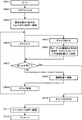
以下、本発明の一実施の形態によるプロキシミティ露光装置のギャップ制御方法について説明する。図6は、本発明の一実施の形態によるプロキシミティ露光装置のギャップ制御方法を示すフローチャートである。マスク2と基板1とのギャップ制御を行う際、まず、図1の主制御装置50は、Z−チルト機構駆動回路64により各Z−チルト機構30を駆動して、マスク2と基板1とのギャップを、目標値よりも一旦狭くする(ステップ301)。ここで、目標値よりも狭くしたマスク2と基板1とのギャップは、目標値に応じ、目標値の10%〜50%程度であって、マスク2と基板1が接触する恐れの無い間隔とする。
Hereinafter, a gap control method for a proximity exposure apparatus according to an embodiment of the present invention will be described. FIG. 6 is a flowchart showing a gap control method of a proximity exposure apparatus according to an embodiment of the present invention. When performing the gap control between the
マスク2と基板1とのギャップを目標値よりも一旦狭くした後、主制御装置50は、Z−チルト機構駆動回路64により各Z−チルト機構30を駆動して、マスク2と基板1とのギャップを目標値に近づける(ステップ302)。各ギャップセンサー40は、マスク2と基板1とのギャップを、マスク2の四隅で測定する(ステップ310)。主制御装置50は、マスク2と基板1とのギャップの目標値、及び各ギャップセンサー40の測定結果に基づき、マスク2と基板1とのギャップが許容範囲内であるか判定し(ステップ320)、マスク2と基板1とのギャップが許容範囲内であれば、ギャップ合わせ動作を終了する。
After the gap between the
マスク2と基板1とのギャップが許容範囲内でない場合、主制御装置50は、マスク2と基板1とのギャップの目標値、及び各ギャップセンサー40の測定結果に基づき、各ギャップセンサー40の測定点での、マスク2を移動する移動量を決定し、それらに基づいて、各Z−チルト機構30を移動する移動量を決定する(ステップ330)。そして、主制御装置50は、Z−チルト機構駆動回路64を駆動して、各Z−チルト機構30を決定した各Z−チルト機構30の移動量だけ移動させて(ステップ340)、ステップ310へ戻る。
When the gap between the
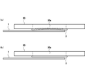
図7(a)はマスクと基板とのギャップを目標値よりも狭くしたときのマスクを示す図、図7(b)はその後にマスクと基板とのギャップを目標値に近づけたときのマスクを示す図である。各Z−チルト機構30により、マスク2と基板1とのギャップを目標値よりも一旦狭くするすると、マスク2と基板1とのギャップを直接目標値にする場合に比べ、より多くの空気がマスク2と基板1との間から逃がされて、マスク2と基板1との間に残る空気が少なくなる。このとき、図7(a)に示す様に、マスク2は、マスク2と基板1との間に残った空気に押されて、マスクホルダ20の開口20a内へ入り込む様に変形している。そして、図7(b)に示す様に、その後にマスク2と基板1とのギャップを目標値に近づけると、マスク2と基板1とのギャップが広がるため、マスク2と基板1との間に残った空気によりマスク2が変形方向と逆方向へ引っ張られて、マスク2の変形が速やかに解消される。
FIG. 7A shows the mask when the gap between the mask and the substrate is narrower than the target value, and FIG. 7B shows the mask when the gap between the mask and the substrate approaches the target value thereafter. FIG. When the gap between the
図6に示した実施の形態によれば、マスク2と基板1とのギャップを、目標値よりも一旦狭くした後に目標値に近づけることにより、マスク2と基板1との間の空気により変形したマスクを速やかに元に戻して、マスク1と基板1とのギャップ合わせを短時間で行うことができる。
According to the embodiment shown in FIG. 6, the gap between the
なお、本発明は、基板の一面を複数のショットに分けて露光する場合、および基板の一面を一括して露光する場合のいずれにも適用される。 Note that the present invention is applicable to both the case where the one surface of the substrate is divided into a plurality of shots and the case where the entire surface of the substrate is exposed.
次に、本発明の他の実施の形態によるプロキシミティ露光装置のギャップ制御方法について説明する。本実施の形態のプロキシミティ露光装置は、露光位置において、基板1をXY方向へステップ移動させて、基板1の一面を複数のショットに分けて露光する。図8は、ショットの領域の一例を示す図である。図8は、基板1の一面を6つのショットに分けて露光する例を示している。1回目のショットで基板1の領域1aが露光され、2回目のショットで基板1の領域1bが露光され、3回目のショットで基板1の領域1cが露光され、4回目のショットで基板1の領域1dが露光され、5回目のショットで基板1の領域1eが露光され、6回目のショットで基板1の領域1fが露光される。
Next, a gap control method for a proximity exposure apparatus according to another embodiment of the present invention will be described. The proximity exposure apparatus according to the present embodiment performs exposure by dividing the surface of the
本実施の形態では、複数の基板を順番に露光する前に、1枚の基板を用いて、ギャップ合わせを行う前のマスク2と基板1とのギャップをほぼ一定にするための、各Z−チルト機構30の各ショットについての登録位置を決定する。図9は、登録位置を決定する動作を示すフローチャートである。1枚の基板に対して、まず、ロード/アンロード位置において、チャック10への基板1のロードが行われる(ステップ401)。主制御装置50は、Xステージ駆動回路61によりXステージ5を駆動し、Yステージ駆動回路62によりYステージ7を駆動し、θステージ駆動回路63によりθステージ8を駆動して、ロード/アンロード位置においてチャック10をXY方向へ移動及びθ方向へ回転させ、基板1のプリアライメントを行う(ステップ402)。次に、主制御装置50は、Xステージ駆動回路61によりXステージ5を駆動し、Yステージ駆動回路62によりYステージ7を駆動して、チャック10を露光位置へ移動させ、基板1を露光位置の1回目のショットを行う位置へ移動させる(ステップ403)。
In this embodiment, before exposing a plurality of substrates in order, each Z− is used to make the gap between the
続いて、主制御装置50は、4つのギャップセンサー40の測定結果に基づき、Z−チルト機構駆動回路64により各Z−チルト機構30を駆動して、マスク2と基板1とのギャップ合わせを行う(ステップ404)。次に、主制御装置50は、Xステージ駆動回路61によりXステージ5を駆動し、Yステージ駆動回路62によりYステージ7を駆動し、θステージ駆動回路63によりθステージ8を駆動して、露光位置においてチャック10をXY方向へ移動及びθ方向へ回転させ、基板1のアライメントを行う(ステップ405)。
Subsequently, the
マスク2と基板1とのギャップ合わせが終了した後、主制御装置50は、ギャップ合わせ後の各Z−チルト機構30のZ方向の位置を、各Z−チルト機構30のそのショットについての登録位置として記憶する(ステップ406)。
After the gap alignment between the
マスク2と基板1とのギャップ合わせが終了した後、主制御装置50は、全ショットについてギャップ合わせが終了したか否かを判断する(ステップ407)。全ショットについてギャップ合わせが終了していない場合、主制御装置50は、Z−チルト機構駆動回路64により各Z−チルト機構30を駆動して、各Z−チルト機構30を、予め決定したマスク2と基板1の接触の恐れが無い退避位置へ移動させる(ステップ408)。続いて、主制御装置50は、Xステージ駆動回路61によりXステージ5を駆動し、Yステージ駆動回路62によりYステージ7を駆動して、基板1のXY方向へのステップ移動を行い(ステップ409)、基板1を次のショットを行う位置へ移動させる。そして、ステップ404へ戻り、全ショットについてギャップ合わせが終了するまで、ステップ404〜409を繰り返す。主制御装置50は、ショット毎に、ギャップ合わせ後の各Z−チルト機構30のZ方向の位置を、各Z−チルト機構30の各ショットについての登録位置として記憶する。
After the gap alignment between
全ショットが終了した場合、主制御装置50は、Z−チルト機構駆動回路64により各Z−チルト機構30を駆動して、マスク2と基板1とのギャップを広げた後(ステップ410)、Xステージ駆動回路61によりXステージ5を駆動し、Yステージ駆動回路62によりYステージ7を駆動して、チャック10をロード/アンロード位置へ移動させる(ステップ411)。そして、ロード/アンロード位置において、チャック10からの基板1のアンロードが行われる(ステップ412)。
When all shots are completed, the
基板1のXY方向へのステップ移動を行い、基板1の一面を複数のショットに分けて露光する場合、基板1を支持するチャック10に緩やかな凹凸や変形等があると、基板1の表面が完全に平坦ではなくなるので、ショット毎に、ギャップ合わせ後の各Z−チルト機構30のZ方向の位置が異なる。1枚の基板に対して、基板1のXY方向へのステップ移動後に、複数のギャップセンサー40によりマスク2と基板1とのギャップを複数箇所で測定し、測定結果に基づき、複数のZ−チルト機構30によりマスク2と基板1とのギャップ合わせを行い、ショット毎に、ギャップ合わせ後の各Z−チルト機構30のZ方向の位置を、各Z−チルト機構30の各ショットについての登録位置として記憶するので、基板1を支持するチャックに緩やかな凹凸や変形等があっても、それ以後の複数の基板に対して、各ショットにおいて各Z−チルト機構30をそのショットについての登録位置へ移動したときのマスク2と基板1とのギャップを、ほぼ一定することができる。
When the
図10は、主制御装置のギャップ合わせ動作を行う部分を示すブロック図である。主制御装置50のギャップ合わせ動作を行う部分は、Z−チルト機構制御部51、メモリ53、移動量算出部54、判定部55、移動量決定部56、及び累積値確認部57を含んで構成されている。Z−チルト機構制御部51は、Z−チルト機構駆動回路64の制御を行い、Z−チルト機構駆動回路64が駆動した各Z−チルト機構30のZ方向の位置を検出する。
FIG. 10 is a block diagram showing a portion for performing the gap matching operation of the main controller. The part that performs the gap alignment operation of the
メモリ53は、マスク2と基板1とのギャップの目標値、及び各ギャップセンサー40の測定点でのマスク2のZ方向の移動量の上限値を予め記憶しており、ショット毎に、Z−チルト機構制御部51が検出したギャップ合わせ後の各Z−チルト機構30のZ方向の位置を、各Z−チルト機構30のそのショットについての登録位置として記憶する(図9のステップ406)。移動量算出部54は、Z−チルト機構制御部51が検出した各Z−チルト機構30のZ方向の位置に基づき、3つのZ−チルト機構30で構成される平面の傾きを算出し、各ギャップセンサー40の測定点でのマスク2の移動量を算出する。
The
図11は、図9のギャップ合わせ動作のフローチャートである。図9に示した登録位置を決定する動作において、マスク2と基板1とのギャップ合わせ(ステップ404)を行う際、まず、各ギャップセンサー40は、マスク2と基板1とのギャップを、マスク2の四隅で測定する(ステップ510)。判定部55は、メモリ53に記憶されたマスク2と基板1とのギャップの目標値、及び各ギャップセンサー40の測定結果に基づき、マスク2と基板1とのギャップが許容範囲内であるか判定し(ステップ520)、マスク2と基板1とのギャップが許容範囲内であれば、ギャップ合わせ動作を終了する。
FIG. 11 is a flowchart of the gap matching operation of FIG. In the operation of determining the registration position shown in FIG. 9, when performing gap alignment between the
マスク2と基板1とのギャップが許容範囲内でない場合、移動量決定部56は、メモリ53に記憶されたマスク2と基板1とのギャップの目標値、及び各ギャップセンサー40の測定結果に基づき、各ギャップセンサー40の測定点での、マスク2を移動する移動量を決定し、それらに基づいて、各Z−チルト機構30を移動する移動量を決定する(ステップ530)。累積値確認部57は、Z−チルト機構制御部51がZ−チルト機構駆動回路64により各Z−チルト機構30を駆動する前に、各ギャップセンサー40の測定点について、移動量算出部54が算出したマスク2の移動量及び移動量決定部56が決定したマスク2の移動量の累積値が、メモリ53に記憶された上限値以下であるか確認する(ステップ540)。移動量の累積値が上限値以下である場合、Z−チルト機構制御部51は、Z−チルト機構駆動回路64を駆動して、各Z−チルト機構30を移動量決定部56が決定した各Z−チルト機構30の移動量だけ移動させ(ステップ550)、ステップ510へ戻る。マスク2の移動量の累積値が上限値以下でない場合、ギャップ合わせ動作を停止する。
When the gap between the
各Z−チルト機構30のZ方向の位置に基づき、各ギャップセンサー40の測定点でのマスク2の移動量を算出し、マスク2と基板1とのギャップの目標値、及びマスク2と基板1とのギャップの測定結果に基づき、各ギャップセンサー40の測定点での、マスク2を移動する移動量を決定し、複数のZ−チルト機構30を駆動する前に、各ギャップセンサー40の測定点について、算出した移動量及び決定した移動量の累積値が上限値以下であるか確認するので、ギャップ合わせ時にマスク2と基板1の接触が防止される。
Based on the position of each Z-
図12は、本発明の他の実施の形態によるプロキシミティ露光装置のギャップ制御方法を用いた露光処理の動作を示すフローチャートである。まず、ロード/アンロード位置において、チャック10への基板1のロードが行われる(ステップ601)。主制御装置50は、Xステージ駆動回路61によりXステージ5を駆動し、Yステージ駆動回路62によりYステージ7を駆動し、θステージ駆動回路63によりθステージ8を駆動して、ロード/アンロード位置においてチャック10をXY方向へ移動及びθ方向へ回転させ、基板1のプリアライメントを行う(ステップ602)。次に、主制御装置50は、Xステージ駆動回路61によりXステージ5を駆動し、Yステージ駆動回路62によりYステージ7を駆動して、チャック10を露光位置へ移動させ、基板1を露光位置の1回目のショットを行う位置へ移動させる(ステップ603)。これと並行して、主制御装置50は、Z−チルト機構駆動回路64により各Z−チルト機構30を駆動して、各Z−チルト機構30を1回目のショットについての登録位置から第1の所定距離だけ上方にある位置へ移動させる(ステップ604)。ここで、第1の所定距離は、基板1のXY方向へのステップ移動時にマスク2と基板1が接触する恐れの無い距離とする。
FIG. 12 is a flowchart showing an exposure process operation using the gap control method of the proximity exposure apparatus according to another embodiment of the present invention. First, the
続いて、主制御装置50は、4つのギャップセンサー40の測定結果に基づき、Z−チルト機構駆動回路64により各Z−チルト機構30を駆動して、マスク2と基板1とのギャップ合わせを行う(ステップ605)。次に、主制御装置50は、Xステージ駆動回路61によりXステージ5を駆動し、Yステージ駆動回路62によりYステージ7を駆動し、θステージ駆動回路63によりθステージ8を駆動して、露光位置においてチャック10をXY方向へ移動及びθ方向へ回転させ、基板1のアライメントを行う(ステップ606)。
Subsequently, the
なお、基板1のアライメント(ステップ606)は、マスク2と基板1とのギャップ合わせ(ステップ605)中に、アライメント用のセンサーが基板1及びマスク2に設けられたアライメント用のマークを検出できる距離にマスク2と基板1が接近した時点から開始してもよい。その場合、マスク2と基板1とのギャップ合わせ(ステップ605)と基板1のアライメント(ステップ606)を一部並行して行うことができるので、タクトタイムが短縮する。
The alignment of the substrate 1 (step 606) is a distance at which the alignment sensor provided on the
マスク2と基板1とのギャップ合わせが終了して、ショット(ステップ607)を行った後、主制御装置50は、全ショットが終了したか否かを判断する(ステップ608)。全ショットが終了していない場合、主制御装置50は、Z−チルト機構駆動回路64により各Z−チルト機構30を駆動して、各Z−チルト機構30を、次のショットについての登録位置から第1の所定距離だけ上方にある位置へ移動させる(ステップ609)。続いて、主制御装置50は、Xステージ駆動回路61によりXステージ5を駆動し、Yステージ駆動回路62によりYステージ7を駆動して、基板1のXY方向へのステップ移動を行い(ステップ610)、基板1を次のショットを行う位置へ移動させる。そして、ステップ605へ戻り、全ショットが終了するまで、ステップ605〜610を繰り返す。
After completing the gap alignment between the
全ショットが終了した場合、主制御装置50は、Z−チルト機構駆動回路64により各Z−チルト機構30を駆動して、マスク2と基板1とのギャップを広げた後(ステップ611)、Xステージ駆動回路61によりXステージ5を駆動し、Yステージ駆動回路62によりYステージ7を駆動して、チャック10をロード/アンロード位置へ移動させる(ステップ612)。そして、ロード/アンロード位置において、チャック10からの基板1のアンロードが行われる(ステップ613)。
When all shots are completed, the
図12に示した露光処理によれば、1枚の基板に対して記憶した、各Z−チルト機構30の各ショットについての登録位置を利用して、それ以後の複数の基板では、ショット毎に、ギャップ合わせ(ステップ605)を行う前のマスク2と基板1とのギャップをほぼ一定にすることができる。
According to the exposure processing shown in FIG. 12, the registered positions for each shot of each Z-
図13は、本発明の他の実施の形態によるプロキシミティ露光装置のギャップ制御方法を示すフローチャートである。図12に示した露光処理において、マスク2と基板1とのギャップ合わせ(ステップ605)を行う際、まず、主制御装置50は、各Z−チルト機構30を、そのショットについての登録位置から第2の所定距離だけ下方にある位置へ移動する(ステップ701)。ここで、第2の所定距離は、マスク2と基板1とのギャップの目標値に応じ、目標値の10%〜50%程度であって、マスク2と基板1が接触する恐れの無い距離とする。このとき、図10の移動量決定部56は、メモリ53に記憶された各Z−チルト機構30の各ショットについての登録位置、及びZ−チルト機構制御部51が検出した各Z−チルト機構30のZ方向の位置に基づき、各Z−チルト機構30の移動量を決定する。Z−チルト機構制御部51は、Z−チルト機構駆動回路64を駆動して、各Z−チルト機構30を移動量決定部56が決定した各Z−チルト機構30の移動量だけ移動させる。
FIG. 13 is a flowchart showing a gap control method of a proximity exposure apparatus according to another embodiment of the present invention. In the exposure processing shown in FIG. 12, when performing gap alignment between the
各Z−チルト機構30を、そのショットについての登録位置から第2の所定距離だけ下方にある位置で停止させた後、主制御装置50は、各Z−チルト機構30を、登録位置へ移動する(ステップ702)。このとき、図10の移動量決定部56は、メモリ53に記憶された各Z−チルト機構30の各ショットについての登録位置、及びZ−チルト機構制御部51が検出した各Z−チルト機構30のZ方向の位置に基づき、各Z−チルト機構30の移動量を決定する。Z−チルト機構制御部51は、Z−チルト機構駆動回路64を駆動して、各Z−チルト機構30を移動量決定部56が決定した各Z−チルト機構30の移動量だけ移動させる。それ以降のステップ710〜750の動作は、図11のステップ510〜550と同様である。
After stopping each Z-
図9〜図13に示した実施の形態によれば、基板1のXY方向へのステップ移動後に、各Z−チルト機構30を、そのショットについての登録位置よりもマスク2と基板1とのギャップが狭くなる位置へ一旦移動した後に登録位置へ移動することにより、各ショットにおいて、マスク2と基板1との間の空気により変形したマスク2を速やかに元に戻して、マスク2と基板1とのギャップ合わせを短時間で行うことができる。
According to the embodiment shown in FIG. 9 to FIG. 13, after the step movement of the
なお、本発明は、基板の一面を複数のショットに分けて露光する場合に限らず、基板の一面を一括して露光する場合にも適用される。 The present invention is not limited to the case where one surface of the substrate is divided into a plurality of shots for exposure, but is also applied to the case where one surface of the substrate is exposed at a time.
本発明のプロキシミティ露光装置を用いて基板の露光を行い、あるいは、本発明のプロキシミティ露光装置のギャップ制御方法を用いてマスクと基板とのギャップ合わせを行って、基板の露光を行うことにより、マスクと基板とのギャップ合わせを短時間で行うことができるので、表示用パネル基板を高いスループットで製造することができる。 By exposing the substrate using the proximity exposure apparatus of the present invention, or by aligning the gap between the mask and the substrate using the gap control method of the proximity exposure apparatus of the present invention. Since the gap between the mask and the substrate can be adjusted in a short time, the display panel substrate can be manufactured with high throughput.
例えば、図14は、液晶ディスプレイ装置のTFT基板の製造工程の一例を示すフローチャートである。薄膜形成工程(ステップ101)では、スパッタ法やプラズマ化学気相成長(CVD)法等により、基板上に液晶駆動用の透明電極となる導電体膜や絶縁体膜等の薄膜を形成する。レジスト塗布工程(ステップ102)では、ロール塗布法等により感光樹脂材料(フォトレジスト)を塗布して、薄膜形成工程(ステップ101)で形成した薄膜上にフォトレジスト膜を形成する。露光工程(ステップ103)では、プロキシミティ露光装置や投影露光装置等を用いて、マスクのパターンをフォトレジスト膜に転写する。現像工程(ステップ104)では、シャワー現像法等により現像液をフォトレジスト膜上に供給して、フォトレジスト膜の不要部分を除去する。エッチング工程(ステップ105)では、ウエットエッチングにより、薄膜形成工程(ステップ101)で形成した薄膜の内、フォトレジスト膜でマスクされていない部分を除去する。剥離工程(ステップ106)では、エッチング工程(ステップ105)でのマスクの役目を終えたフォトレジスト膜を、剥離液によって剥離する。これらの各工程の前又は後には、必要に応じて、基板の洗浄/乾燥工程が実施される。これらの工程を数回繰り返して、基板上にTFTアレイが形成される。 For example, FIG. 14 is a flowchart showing an example of the manufacturing process of the TFT substrate of the liquid crystal display device. In the thin film formation step (step 101), a thin film such as a conductor film or an insulator film, which becomes a transparent electrode for driving liquid crystal, is formed on the substrate by sputtering, plasma chemical vapor deposition (CVD), or the like. In the resist coating process (step 102), a photosensitive resin material (photoresist) is applied by a roll coating method or the like, and a photoresist film is formed on the thin film formed in the thin film forming process (step 101). In the exposure step (step 103), the mask pattern is transferred to the photoresist film using a proximity exposure apparatus, a projection exposure apparatus, or the like. In the development step (step 104), a developer is supplied onto the photoresist film by a shower development method or the like to remove unnecessary portions of the photoresist film. In the etching process (step 105), a portion of the thin film formed in the thin film formation process (step 101) that is not masked by the photoresist film is removed by wet etching. In the stripping step (step 106), the photoresist film that has finished the role of the mask in the etching step (step 105) is stripped with a stripping solution. Before or after each of these steps, a substrate cleaning / drying step is performed as necessary. These steps are repeated several times to form a TFT array on the substrate.
また、図15は、液晶ディスプレイ装置のカラーフィルタ基板の製造工程の一例を示すフローチャートである。ブラックマトリクス形成工程(ステップ201)では、レジスト塗布、露光、現像、エッチング、剥離等の処理により、基板上にブラックマトリクスを形成する。着色パターン形成工程(ステップ202)では、染色法、顔料分散法、印刷法、電着法等により、基板上に着色パターンを形成する。この工程を、R、G、Bの着色パターンについて繰り返す。保護膜形成工程(ステップ203)では、着色パターンの上に保護膜を形成し、透明電極膜形成工程(ステップ204)では、保護膜の上に透明電極膜を形成する。これらの各工程の前、途中又は後には、必要に応じて、基板の洗浄/乾燥工程が実施される。 FIG. 15 is a flowchart showing an example of the manufacturing process of the color filter substrate of the liquid crystal display device. In the black matrix forming step (step 201), a black matrix is formed on the substrate by processing such as resist coating, exposure, development, etching, and peeling. In the colored pattern forming step (step 202), a colored pattern is formed on the substrate by a dyeing method, a pigment dispersion method, a printing method, an electrodeposition method, or the like. This process is repeated for the R, G, and B coloring patterns. In the protective film forming step (step 203), a protective film is formed on the colored pattern, and in the transparent electrode film forming step (step 204), a transparent electrode film is formed on the protective film. Before, during or after each of these steps, a substrate cleaning / drying step is performed as necessary.
図14に示したTFT基板の製造工程では、露光工程(ステップ103)において、図15に示したカラーフィルタ基板の製造工程では、ブラックマトリクス形成工程(ステップ201)及び着色パターン形成工程(ステップ202)の露光処理において、本発明のプロキシミティ露光装置又は本発明のプロキシミティ露光装置のギャップ制御方法を適用することができる。 In the TFT substrate manufacturing process shown in FIG. 14, in the exposure process (step 103), in the color filter substrate manufacturing process shown in FIG. 15, in the black matrix forming process (step 201) and the colored pattern forming process (step 202). In this exposure process, the proximity exposure apparatus of the present invention or the gap control method of the proximity exposure apparatus of the present invention can be applied.
1 基板
2 マスク
3 ベース
4 Xガイド
5 Xステージ
6 Yガイド
7 Yステージ
8 θステージ
9 チャック支持台
10 チャック
20 マスクホルダ
21 ホルダフレーム
22 トップフレーム
23 エアクッション
24 チルト用腕
30 Z−チルト機構
31 ケーシング
32 直動ガイド
33 可動ブロック
34 モータ
35 軸継手
36a ボールねじ
36b ナット
37 ボール
40 ギャップセンサー
41 レーザー光源
42 コリメーションレンズ群
43 投影レンズ
44,45 ミラー
46 結像レンズ
47 CCDラインセンサー
50 主制御装置
51 Z−チルト機構制御部
53 メモリ
54 移動量算出部
55 判定部
56 移動量決定部
57 累積値確認部
61 Xステージ駆動回路
62 Yステージ駆動回路
63 θステージ駆動回路
64 Z−チルト機構駆動回路
DESCRIPTION OF
Claims (12)
前記マスクホルダと前記チャックとを相対的にZ方向へ移動及びチルトする複数のZ−チルト機構と、
マスクと基板とのギャップを複数箇所で測定する複数のギャップセンサーと、
前記複数のZ−チルト機構を駆動する駆動回路と、
前記駆動回路を制御する制御装置とを備え、
前記制御装置は、
前記駆動回路により前記複数のZ−チルト機構を駆動して、マスクと基板とのギャップを、目標値よりも一旦狭くした後に目標値に近づけ、
前記複数のギャップセンサーの測定結果に基づき、前記駆動回路により前記複数のZ−チルト機構を駆動して、マスクと基板とのギャップ合わせを行うことを特徴とするプロキシミティ露光装置。 In a proximity exposure apparatus including a chuck that supports a substrate and a mask holder that holds a mask,
A plurality of Z-tilt mechanisms for relatively moving and tilting the mask holder and the chuck in the Z direction;
Multiple gap sensors that measure the gap between the mask and the substrate at multiple locations;
A drive circuit for driving the plurality of Z-tilt mechanisms;
A control device for controlling the drive circuit,
The controller is
The plurality of Z-tilt mechanisms are driven by the drive circuit, the gap between the mask and the substrate is once narrower than the target value, and then approaches the target value.
A proximity exposure apparatus characterized in that, based on the measurement results of the plurality of gap sensors, the plurality of Z-tilt mechanisms are driven by the drive circuit to perform gap alignment between the mask and the substrate.
マスクホルダとチャックとを相対的にZ方向へ移動及びチルトする複数のZ−チルト機構と、マスクと基板とのギャップを複数箇所で測定する複数のギャップセンサーとを設け、
複数のZ−チルト機構により、マスクと基板とのギャップを、目標値よりも一旦狭くした後に目標値に近づけ、
複数のギャップセンサーによりマスクと基板とのギャップを複数箇所で測定し、測定結果に基づき、複数のZ−チルト機構によりマスクと基板とのギャップ合わせを行うことを特徴とするプロキシミティ露光装置のギャップ制御方法。 A gap control method for a proximity exposure apparatus comprising a chuck for supporting a substrate and a mask holder for holding a mask,
A plurality of Z-tilt mechanisms that move and tilt the mask holder and the chuck in the Z direction relatively, and a plurality of gap sensors that measure the gap between the mask and the substrate at a plurality of locations,
With a plurality of Z-tilt mechanisms, the gap between the mask and the substrate is once narrower than the target value and then brought closer to the target value.
A gap of a proximity exposure apparatus, wherein a gap between a mask and a substrate is measured at a plurality of positions by a plurality of gap sensors, and the gap between the mask and the substrate is adjusted by a plurality of Z-tilt mechanisms based on the measurement result. Control method.
前記マスクホルダと前記チャックとを相対的にZ方向へ移動及びチルトする複数のZ−チルト機構と、
マスクと基板とのギャップを複数箇所で測定する複数のギャップセンサーと、
前記複数のZ−チルト機構を駆動する駆動回路と、
前記駆動回路を制御する制御装置とを備え、
前記制御装置は、
1枚の基板に対して、前記複数のギャップセンサーの測定結果に基づき、前記駆動回路により前記複数のZ−チルト機構を駆動して、マスクと基板とのギャップ合わせを行い、ギャップ合わせ後の各Z−チルト機構のZ方向の位置を、各Z−チルト機構の登録位置として記憶し、
それ以後の複数の基板に対して、前記駆動回路により前記複数のZ−チルト機構を駆動して、各Z−チルト機構を、登録位置よりもマスクと基板とのギャップが狭くなる位置へ一旦移動した後に登録位置へ移動し、前記複数のギャップセンサーの測定結果に基づき、前記駆動回路により前記複数のZ−チルト機構を駆動して、マスクと基板とのギャップ合わせを行うことを特徴とするプロキシミティ露光装置。 In a proximity exposure apparatus including a chuck that supports a substrate and a mask holder that holds a mask,
A plurality of Z-tilt mechanisms for relatively moving and tilting the mask holder and the chuck in the Z direction;
Multiple gap sensors that measure the gap between the mask and the substrate at multiple locations;
A drive circuit for driving the plurality of Z-tilt mechanisms;
A control device for controlling the drive circuit,
The controller is
Based on the measurement results of the plurality of gap sensors on one substrate, the drive circuit drives the plurality of Z-tilt mechanisms to perform gap alignment between the mask and the substrate. The Z direction position of the Z-tilt mechanism is stored as a registered position of each Z-tilt mechanism,
Thereafter, the plurality of Z-tilt mechanisms are driven by the drive circuit with respect to a plurality of subsequent substrates, and each Z-tilt mechanism is temporarily moved to a position where the gap between the mask and the substrate is narrower than the registered position. After that, the proxy moves to a registration position, and based on the measurement results of the plurality of gap sensors, the plurality of Z-tilt mechanisms are driven by the drive circuit to perform gap alignment between the mask and the substrate. Mitty exposure equipment.
マスクホルダとチャックとを相対的にZ方向へ移動及びチルトする複数のZ−チルト機構と、マスクと基板とのギャップを複数箇所で測定する複数のギャップセンサーとを設け、
1枚の基板に対して、
複数のギャップセンサーによりマスクと基板とのギャップを複数箇所で測定し、測定結果に基づき、複数のZ−チルト機構によりマスクと基板とのギャップ合わせを行い、
ギャップ合わせ後の各Z−チルト機構のZ方向の位置を、各Z−チルト機構の登録位置として記憶し、
それ以後の複数の基板に対して、
各Z−チルト機構を、登録位置よりもマスクと基板とのギャップが狭くなる位置へ一旦移動した後に登録位置へ移動し、複数のギャップセンサーによりマスクと基板とのギャップを複数箇所で測定し、測定結果に基づき、複数のZ−チルト機構によりマスクと基板とのギャップ合わせを行うことを特徴とするプロキシミティ露光装置のギャップ制御方法。 A gap control method for a proximity exposure apparatus comprising a chuck for supporting a substrate and a mask holder for holding a mask,
A plurality of Z-tilt mechanisms that move and tilt the mask holder and the chuck in the Z direction relatively, and a plurality of gap sensors that measure the gap between the mask and the substrate at a plurality of locations,
For one board,
The gap between the mask and the substrate is measured at a plurality of positions by a plurality of gap sensors, and based on the measurement result, the gap between the mask and the substrate is adjusted by a plurality of Z-tilt mechanisms.
The Z-direction position of each Z-tilt mechanism after gap adjustment is stored as the registered position of each Z-tilt mechanism,
For multiple boards after that,
Each Z-tilt mechanism is moved once to a position where the gap between the mask and the substrate becomes narrower than the registration position and then moved to the registration position, and the gap between the mask and the substrate is measured at a plurality of locations by a plurality of gap sensors. A gap control method for a proximity exposure apparatus, wherein a gap between a mask and a substrate is aligned by a plurality of Z-tilt mechanisms based on a measurement result.
前記マスクホルダと前記チャックとを相対的にZ方向へ移動及びチルトする複数のZ−チルト機構と、
マスクと基板とのギャップを複数箇所で測定する複数のギャップセンサーと、
前記複数のZ−チルト機構を駆動する駆動回路と、
前記駆動回路を制御する制御装置とを備え、
前記制御装置は、
1枚の基板に対して、基板のXY方向へのステップ移動後に、前記複数のギャップセンサーの測定結果に基づき、前記駆動回路により前記複数のZ−チルト機構を駆動して、マスクと基板とのギャップ合わせを行い、ショット毎に、ギャップ合わせ後の各Z−チルト機構のZ方向の位置を、各Z−チルト機構の各ショットについての登録位置として記憶し、
それ以後の複数の基板に対して、基板のXY方向へのステップ移動後に、前記駆動回路により前記複数のZ−チルト機構を駆動して、各Z−チルト機構を、そのショットについての登録位置よりもマスクと基板とのギャップが狭くなる位置へ一旦移動した後に登録位置へ移動し、前記複数のギャップセンサーの測定結果に基づき、前記駆動回路により前記複数のZ−チルト機構を駆動して、マスクと基板とのギャップ合わせを行うことを特徴とするプロキシミティ露光装置。 A chuck for supporting the substrate, a mask holder for holding the mask, and a stage for moving the chuck are provided. The chuck is moved by the stage to perform step movement of the substrate in the XY directions, and a plurality of surfaces of the substrate are arranged. In proximity exposure equipment that divides and exposes shots,
A plurality of Z-tilt mechanisms for relatively moving and tilting the mask holder and the chuck in the Z direction;
Multiple gap sensors that measure the gap between the mask and the substrate at multiple locations;
A drive circuit for driving the plurality of Z-tilt mechanisms;
A control device for controlling the drive circuit,
The controller is
After the step movement of the substrate in the XY direction with respect to one substrate, based on the measurement results of the plurality of gap sensors, the drive circuit drives the plurality of Z-tilt mechanisms to Gap alignment is performed, and for each shot, the Z-direction position of each Z-tilt mechanism after gap alignment is stored as a registered position for each shot of each Z-tilt mechanism.
After the step movement of the substrate in the XY directions with respect to the plurality of substrates thereafter, the plurality of Z-tilt mechanisms are driven by the drive circuit, and each Z-tilt mechanism is moved from the registration position for the shot. The mask is moved once to a position where the gap between the mask and the substrate is narrowed and then moved to a registration position. Based on the measurement results of the plurality of gap sensors, the drive circuit drives the plurality of Z-tilt mechanisms to Proximity exposure apparatus characterized in that a gap is aligned with a substrate.
マスクホルダとチャックとを相対的にZ方向へ移動及びチルトする複数のZ−チルト機構と、マスクと基板とのギャップを複数箇所で測定する複数のギャップセンサーとを設け、
1枚の基板に対して、
基板のXY方向へのステップ移動後に、複数のギャップセンサーによりマスクと基板とのギャップを複数箇所で測定し、測定結果に基づき、複数のZ−チルト機構によりマスクと基板とのギャップ合わせを行い、
ショット毎に、ギャップ合わせ後の各Z−チルト機構のZ方向の位置を、各Z−チルト機構の各ショットについての登録位置として記憶し、
それ以後の複数の基板に対して、
基板のXY方向へのステップ移動後に、各Z−チルト機構を、そのショットについての登録位置よりもマスクと基板とのギャップが狭くなる位置へ一旦移動した後に登録位置へ移動し、複数のギャップセンサーによりマスクと基板とのギャップを複数箇所で測定し、測定結果に基づき、複数のZ−チルト機構によりマスクと基板とのギャップ合わせを行うことを特徴とするプロキシミティ露光装置のギャップ制御方法。 A chuck for supporting the substrate, a mask holder for holding the mask, and a stage for moving the chuck are provided. The chuck is moved by the stage to perform step movement of the substrate in the XY directions so that one surface of the substrate is made into a plurality of shots. A gap control method for a proximity exposure apparatus that performs exposure separately.
A plurality of Z-tilt mechanisms that move and tilt the mask holder and the chuck in the Z direction relatively, and a plurality of gap sensors that measure the gap between the mask and the substrate at a plurality of locations,
For one board,
After step movement in the XY direction of the substrate, the gap between the mask and the substrate is measured at a plurality of positions by a plurality of gap sensors, and based on the measurement result, the gap between the mask and the substrate is adjusted by a plurality of Z-tilt mechanisms.
For each shot, the position in the Z direction of each Z-tilt mechanism after gap alignment is stored as a registered position for each shot of each Z-tilt mechanism,
For multiple boards after that,
After the step movement of the substrate in the XY directions, each Z-tilt mechanism is moved once to a position where the gap between the mask and the substrate becomes narrower than the registration position for the shot and then moved to the registration position, and a plurality of gap sensors A gap control method for a proximity exposure apparatus, characterized in that a gap between a mask and a substrate is measured at a plurality of locations by a plurality of positions, and a gap between the mask and the substrate is adjusted by a plurality of Z-tilt mechanisms based on the measurement result.
Priority Applications (1)
| Application Number | Priority Date | Filing Date | Title |
|---|---|---|---|
| JP2009278466A JP2011123103A (en) | 2009-12-08 | 2009-12-08 | Proximity exposure apparatus, method for controlling gap of proximity exposure apparatus, and method for manufacturing display panel substrate |
Applications Claiming Priority (1)
| Application Number | Priority Date | Filing Date | Title |
|---|---|---|---|
| JP2009278466A JP2011123103A (en) | 2009-12-08 | 2009-12-08 | Proximity exposure apparatus, method for controlling gap of proximity exposure apparatus, and method for manufacturing display panel substrate |
Publications (1)
| Publication Number | Publication Date |
|---|---|
| JP2011123103A true JP2011123103A (en) | 2011-06-23 |
Family
ID=44287077
Family Applications (1)
| Application Number | Title | Priority Date | Filing Date |
|---|---|---|---|
| JP2009278466A Pending JP2011123103A (en) | 2009-12-08 | 2009-12-08 | Proximity exposure apparatus, method for controlling gap of proximity exposure apparatus, and method for manufacturing display panel substrate |
Country Status (1)
| Country | Link |
|---|---|
| JP (1) | JP2011123103A (en) |
Cited By (1)
| Publication number | Priority date | Publication date | Assignee | Title |
|---|---|---|---|---|
| KR20140028245A (en) * | 2012-08-28 | 2014-03-10 | 엘지디스플레이 주식회사 | Proximity type exposure apparatus and exposure method using the same |
Citations (5)
| Publication number | Priority date | Publication date | Assignee | Title |
|---|---|---|---|---|
| JPH04107911A (en) * | 1990-08-29 | 1992-04-09 | Fujitsu Ltd | Method and device for transferring pattern by use of x-ray mask |
| JPH0562886A (en) * | 1991-09-04 | 1993-03-12 | Matsushita Electric Ind Co Ltd | Exposing method for x-ray |
| JP2003015310A (en) * | 2001-07-02 | 2003-01-17 | Hitachi Electronics Eng Co Ltd | Proximity exposure device, and method of correcting deformation of photomask in the device |
| JP2005099094A (en) * | 2003-09-22 | 2005-04-14 | Hitachi High-Tech Electronics Engineering Co Ltd | Method and device for substrate exposure, method for manufacturing display panel, and display device |
| JP2006098774A (en) * | 2004-09-29 | 2006-04-13 | Nsk Ltd | Proximity exposure apparatus |
-
2009
- 2009-12-08 JP JP2009278466A patent/JP2011123103A/en active Pending
Patent Citations (5)
| Publication number | Priority date | Publication date | Assignee | Title |
|---|---|---|---|---|
| JPH04107911A (en) * | 1990-08-29 | 1992-04-09 | Fujitsu Ltd | Method and device for transferring pattern by use of x-ray mask |
| JPH0562886A (en) * | 1991-09-04 | 1993-03-12 | Matsushita Electric Ind Co Ltd | Exposing method for x-ray |
| JP2003015310A (en) * | 2001-07-02 | 2003-01-17 | Hitachi Electronics Eng Co Ltd | Proximity exposure device, and method of correcting deformation of photomask in the device |
| JP2005099094A (en) * | 2003-09-22 | 2005-04-14 | Hitachi High-Tech Electronics Engineering Co Ltd | Method and device for substrate exposure, method for manufacturing display panel, and display device |
| JP2006098774A (en) * | 2004-09-29 | 2006-04-13 | Nsk Ltd | Proximity exposure apparatus |
Cited By (2)
| Publication number | Priority date | Publication date | Assignee | Title |
|---|---|---|---|---|
| KR20140028245A (en) * | 2012-08-28 | 2014-03-10 | 엘지디스플레이 주식회사 | Proximity type exposure apparatus and exposure method using the same |
| KR101977182B1 (en) | 2012-08-28 | 2019-05-10 | 엘지디스플레이 주식회사 | Proximity Type Exposure Apparatus And Exposure Method Using The Same |
Similar Documents
| Publication | Publication Date | Title |
|---|---|---|
| KR101057765B1 (en) | Exposure apparatus, exposure method, and manufacturing method of panel substrate for display | |
| KR101084620B1 (en) | Proximity exposure apparatus, method of delivering a mask thereof and method of manufacturing a panel substrate | |
| JP2019086709A (en) | Exposure system, exposure method, and manufacturing method of panel substrate for display | |
| JP4808676B2 (en) | Exposure apparatus, exposure method, and manufacturing method of display panel substrate | |
| JP2011192867A (en) | Proximity exposure apparatus, method of controlling stage temperature of the same, and method of manufacturing display panel substrate | |
| KR101148241B1 (en) | Proximity exposure apparatus, method for determining a substrate position in the proximity exposure apparatus and method of manufacturing a display panel substrate | |
| JP2013195531A (en) | Proximity exposure apparatus, alignment method of proximity exposure apparatus, and method of manufacturing display panel substrate | |
| JP2011003605A (en) | Proximity aligner, alignment method for proximity aligner, and manufacturing method for display panel board | |
| JP5537063B2 (en) | Proximity exposure apparatus, gap control method for proximity exposure apparatus, and method for manufacturing display panel substrate | |
| JP2014071315A (en) | Alignment mark detection device, proximity exposure apparatus, and alignment method of substrate | |
| JP5687165B2 (en) | Proximity exposure apparatus, substrate positioning method for proximity exposure apparatus, and display panel substrate manufacturing method | |
| JP2011123103A (en) | Proximity exposure apparatus, method for controlling gap of proximity exposure apparatus, and method for manufacturing display panel substrate | |
| JP5392946B2 (en) | Proximity exposure apparatus, mask transfer method for proximity exposure apparatus, and method for manufacturing display panel substrate | |
| JP5441770B2 (en) | Proximity exposure apparatus, gap control method for proximity exposure apparatus, and method for manufacturing display panel substrate | |
| JP5306020B2 (en) | Proximity exposure apparatus, substrate moving method of proximity exposure apparatus, and display panel substrate manufacturing method | |
| JP5320552B2 (en) | Proximity exposure apparatus, mask holding method of proximity exposure apparatus, and display panel substrate manufacturing method | |
| JP2013054270A (en) | Proximity exposure apparatus, gap control method for proximity exposure apparatus and manufacturing method of panel substrate for display | |
| JP2013205678A (en) | Proximity exposure device, substrate positioning method of proximity exposure device, and manufacturing method of display panel substrate | |
| JP2010176081A (en) | Exposure device, substrate carrying method of same, production method of panel substrate for display | |
| JP2012032666A (en) | Exposure equipment, exposure method and method for manufacturing panel substrate for display | |
| JP2012234021A (en) | Proximity exposure apparatus, method for aligning proximity exposure apparatus, and method for manufacturing display panel substrate | |
| JP2011227213A (en) | Proximity exposure apparatus, alignment method of proximity exposure apparatus and manufacturing method of display panel substrate | |
| JP2008009012A (en) | Exposure device, exposure method, and method for manufacturing panel substrate for display | |
| JP2012068434A (en) | Proximity exposure apparatus, method for aligning proximity exposure apparatus, and method for manufacturing display panel substrate | |
| JP5441800B2 (en) | Proximity exposure apparatus, substrate positioning method for proximity exposure apparatus, display panel substrate manufacturing method, and minute angle detection method using optical displacement meter |
Legal Events
| Date | Code | Title | Description |
|---|---|---|---|
| A621 | Written request for application examination |
Free format text: JAPANESE INTERMEDIATE CODE: A621 Effective date: 20120403 |
|
| A977 | Report on retrieval |
Free format text: JAPANESE INTERMEDIATE CODE: A971007 Effective date: 20130913 |
|
| A131 | Notification of reasons for refusal |
Free format text: JAPANESE INTERMEDIATE CODE: A131 Effective date: 20130924 |
|
| A02 | Decision of refusal |
Free format text: JAPANESE INTERMEDIATE CODE: A02 Effective date: 20140204 |