JP5147719B2 - Method and apparatus for performing pulsed field nerve modulation via intravascular-extravascular approach - Google Patents
Method and apparatus for performing pulsed field nerve modulation via intravascular-extravascular approach Download PDFInfo
- Publication number
- JP5147719B2 JP5147719B2 JP2008548632A JP2008548632A JP5147719B2 JP 5147719 B2 JP5147719 B2 JP 5147719B2 JP 2008548632 A JP2008548632 A JP 2008548632A JP 2008548632 A JP2008548632 A JP 2008548632A JP 5147719 B2 JP5147719 B2 JP 5147719B2
- Authority
- JP
- Japan
- Prior art keywords
- electrode
- blood vessel
- extravascular
- electric field
- bipolar
- Prior art date
- Legal status (The legal status is an assumption and is not a legal conclusion. Google has not performed a legal analysis and makes no representation as to the accuracy of the status listed.)
- Expired - Fee Related
Links
Images


Classifications
-
- A—HUMAN NECESSITIES
- A61—MEDICAL OR VETERINARY SCIENCE; HYGIENE
- A61B—DIAGNOSIS; SURGERY; IDENTIFICATION
- A61B18/00—Surgical instruments, devices or methods for transferring non-mechanical forms of energy to or from the body
- A61B18/04—Surgical instruments, devices or methods for transferring non-mechanical forms of energy to or from the body by heating
- A61B18/12—Surgical instruments, devices or methods for transferring non-mechanical forms of energy to or from the body by heating by passing a current through the tissue to be heated, e.g. high-frequency current
- A61B18/14—Probes or electrodes therefor
- A61B18/1477—Needle-like probes
-
- A—HUMAN NECESSITIES
- A61—MEDICAL OR VETERINARY SCIENCE; HYGIENE
- A61N—ELECTROTHERAPY; MAGNETOTHERAPY; RADIATION THERAPY; ULTRASOUND THERAPY
- A61N1/00—Electrotherapy; Circuits therefor
- A61N1/18—Applying electric currents by contact electrodes
- A61N1/32—Applying electric currents by contact electrodes alternating or intermittent currents
- A61N1/321—Electromedical belts
-
- A—HUMAN NECESSITIES
- A61—MEDICAL OR VETERINARY SCIENCE; HYGIENE
- A61B—DIAGNOSIS; SURGERY; IDENTIFICATION
- A61B18/00—Surgical instruments, devices or methods for transferring non-mechanical forms of energy to or from the body
- A61B18/04—Surgical instruments, devices or methods for transferring non-mechanical forms of energy to or from the body by heating
- A61B18/12—Surgical instruments, devices or methods for transferring non-mechanical forms of energy to or from the body by heating by passing a current through the tissue to be heated, e.g. high-frequency current
- A61B18/1206—Generators therefor
-
- A—HUMAN NECESSITIES
- A61—MEDICAL OR VETERINARY SCIENCE; HYGIENE
- A61M—DEVICES FOR INTRODUCING MEDIA INTO, OR ONTO, THE BODY; DEVICES FOR TRANSDUCING BODY MEDIA OR FOR TAKING MEDIA FROM THE BODY; DEVICES FOR PRODUCING OR ENDING SLEEP OR STUPOR
- A61M37/00—Other apparatus for introducing media into the body; Percutany, i.e. introducing medicines into the body by diffusion through the skin
-
- A—HUMAN NECESSITIES
- A61—MEDICAL OR VETERINARY SCIENCE; HYGIENE
- A61M—DEVICES FOR INTRODUCING MEDIA INTO, OR ONTO, THE BODY; DEVICES FOR TRANSDUCING BODY MEDIA OR FOR TAKING MEDIA FROM THE BODY; DEVICES FOR PRODUCING OR ENDING SLEEP OR STUPOR
- A61M5/00—Devices for bringing media into the body in a subcutaneous, intra-vascular or intramuscular way; Accessories therefor, e.g. filling or cleaning devices, arm-rests
- A61M5/14—Infusion devices, e.g. infusing by gravity; Blood infusion; Accessories therefor
-
- A—HUMAN NECESSITIES
- A61—MEDICAL OR VETERINARY SCIENCE; HYGIENE
- A61N—ELECTROTHERAPY; MAGNETOTHERAPY; RADIATION THERAPY; ULTRASOUND THERAPY
- A61N1/00—Electrotherapy; Circuits therefor
- A61N1/02—Details
- A61N1/04—Electrodes
- A61N1/05—Electrodes for implantation or insertion into the body, e.g. heart electrode
- A61N1/0507—Electrodes for the digestive system
- A61N1/0514—Electrodes for the urinary tract
-
- A—HUMAN NECESSITIES
- A61—MEDICAL OR VETERINARY SCIENCE; HYGIENE
- A61N—ELECTROTHERAPY; MAGNETOTHERAPY; RADIATION THERAPY; ULTRASOUND THERAPY
- A61N1/00—Electrotherapy; Circuits therefor
- A61N1/02—Details
- A61N1/04—Electrodes
- A61N1/05—Electrodes for implantation or insertion into the body, e.g. heart electrode
- A61N1/0551—Spinal or peripheral nerve electrodes
-
- A—HUMAN NECESSITIES
- A61—MEDICAL OR VETERINARY SCIENCE; HYGIENE
- A61N—ELECTROTHERAPY; MAGNETOTHERAPY; RADIATION THERAPY; ULTRASOUND THERAPY
- A61N1/00—Electrotherapy; Circuits therefor
- A61N1/18—Applying electric currents by contact electrodes
- A61N1/32—Applying electric currents by contact electrodes alternating or intermittent currents
- A61N1/327—Applying electric currents by contact electrodes alternating or intermittent currents for enhancing the absorption properties of tissue, e.g. by electroporation
-
- A—HUMAN NECESSITIES
- A61—MEDICAL OR VETERINARY SCIENCE; HYGIENE
- A61N—ELECTROTHERAPY; MAGNETOTHERAPY; RADIATION THERAPY; ULTRASOUND THERAPY
- A61N1/00—Electrotherapy; Circuits therefor
- A61N1/18—Applying electric currents by contact electrodes
- A61N1/32—Applying electric currents by contact electrodes alternating or intermittent currents
- A61N1/36—Applying electric currents by contact electrodes alternating or intermittent currents for stimulation
- A61N1/36007—Applying electric currents by contact electrodes alternating or intermittent currents for stimulation of urogenital or gastrointestinal organs, e.g. for incontinence control
-
- A—HUMAN NECESSITIES
- A61—MEDICAL OR VETERINARY SCIENCE; HYGIENE
- A61B—DIAGNOSIS; SURGERY; IDENTIFICATION
- A61B18/00—Surgical instruments, devices or methods for transferring non-mechanical forms of energy to or from the body
- A61B2018/00053—Mechanical features of the instrument of device
- A61B2018/00214—Expandable means emitting energy, e.g. by elements carried thereon
- A61B2018/0022—Balloons
-
- A—HUMAN NECESSITIES
- A61—MEDICAL OR VETERINARY SCIENCE; HYGIENE
- A61B—DIAGNOSIS; SURGERY; IDENTIFICATION
- A61B18/00—Surgical instruments, devices or methods for transferring non-mechanical forms of energy to or from the body
- A61B2018/00053—Mechanical features of the instrument of device
- A61B2018/00214—Expandable means emitting energy, e.g. by elements carried thereon
- A61B2018/00267—Expandable means emitting energy, e.g. by elements carried thereon having a basket shaped structure
-
- A—HUMAN NECESSITIES
- A61—MEDICAL OR VETERINARY SCIENCE; HYGIENE
- A61B—DIAGNOSIS; SURGERY; IDENTIFICATION
- A61B18/00—Surgical instruments, devices or methods for transferring non-mechanical forms of energy to or from the body
- A61B2018/00315—Surgical instruments, devices or methods for transferring non-mechanical forms of energy to or from the body for treatment of particular body parts
- A61B2018/00345—Vascular system
- A61B2018/00404—Blood vessels other than those in or around the heart
-
- A—HUMAN NECESSITIES
- A61—MEDICAL OR VETERINARY SCIENCE; HYGIENE
- A61B—DIAGNOSIS; SURGERY; IDENTIFICATION
- A61B18/00—Surgical instruments, devices or methods for transferring non-mechanical forms of energy to or from the body
- A61B2018/00315—Surgical instruments, devices or methods for transferring non-mechanical forms of energy to or from the body for treatment of particular body parts
- A61B2018/00434—Neural system
-
- A—HUMAN NECESSITIES
- A61—MEDICAL OR VETERINARY SCIENCE; HYGIENE
- A61B—DIAGNOSIS; SURGERY; IDENTIFICATION
- A61B18/00—Surgical instruments, devices or methods for transferring non-mechanical forms of energy to or from the body
- A61B2018/00315—Surgical instruments, devices or methods for transferring non-mechanical forms of energy to or from the body for treatment of particular body parts
- A61B2018/00505—Urinary tract
-
- A—HUMAN NECESSITIES
- A61—MEDICAL OR VETERINARY SCIENCE; HYGIENE
- A61B—DIAGNOSIS; SURGERY; IDENTIFICATION
- A61B18/00—Surgical instruments, devices or methods for transferring non-mechanical forms of energy to or from the body
- A61B2018/00571—Surgical instruments, devices or methods for transferring non-mechanical forms of energy to or from the body for achieving a particular surgical effect
- A61B2018/00613—Irreversible electroporation
-
- A—HUMAN NECESSITIES
- A61—MEDICAL OR VETERINARY SCIENCE; HYGIENE
- A61B—DIAGNOSIS; SURGERY; IDENTIFICATION
- A61B18/00—Surgical instruments, devices or methods for transferring non-mechanical forms of energy to or from the body
- A61B18/04—Surgical instruments, devices or methods for transferring non-mechanical forms of energy to or from the body by heating
- A61B18/12—Surgical instruments, devices or methods for transferring non-mechanical forms of energy to or from the body by heating by passing a current through the tissue to be heated, e.g. high-frequency current
- A61B18/1206—Generators therefor
- A61B2018/1246—Generators therefor characterised by the output polarity
- A61B2018/126—Generators therefor characterised by the output polarity bipolar
Description
本発明は、神経変調のための方法及び装置に係る。より詳細には、本発明は、血管内−血管外の接近路を経てパルス電界神経変調を達成するための方法及び装置に係る。 The present invention relates to a method and apparatus for neuromodulation. More particularly, the present invention relates to a method and apparatus for achieving pulsed field neuromodulation via an intravascular-extravascular approach.
参考としての援用:本明細書に述べる全ての出版物や特許出願は、各個々の出版物又は特許出願が参考として援用されると特に及び個々に指示された場合と同程度に、参考としてここに援用されるものとする。 INCORPORATION BY REFERENCE: All publications and patent applications mentioned herein are hereby incorporated by reference, as if each individual publication or patent application was incorporated by reference and to the same extent as specifically indicated. Shall be incorporated in
うっ血性心不全(CHF)とは、心臓がダメージを受け、身体の器官への血液流を減少するときに生じる症状である。血液流が著しく減少する場合には、腎臓の機能が損なわれ、流れの停滞、異常なホルモン分泌、及び血管収縮の増加を招く。その結果、心臓の負担が増加すると共に、腎臓や循環系を通して血液をポンプ送りするための心臓の容量が更に減少する。 Congestive heart failure (CHF) is a condition that occurs when the heart is damaged and reduces blood flow to the organs of the body. If blood flow is significantly reduced, kidney function is impaired, leading to flow stagnation, abnormal hormone secretion, and increased vasoconstriction. As a result, the burden on the heart increases and the volume of the heart for pumping blood through the kidneys and circulatory system further decreases.
腎臓の次第に減少する潅流は、CHFの螺旋状悪化を永続させる主たる非心臓原因であると考えられる。更に、これらの生理学的変化により生じる流体の過負荷及びそれに関連した臨床学的兆候は、付加的な入院や、生活の質低下や、健康管理システムに対する付加的なコストを招く。 Decreasing perfusion of the kidney is thought to be the primary non-cardiac cause that perpetuates the helical deterioration of CHF. In addition, fluid overload and associated clinical signs resulting from these physiological changes result in additional hospitalization, poor quality of life, and additional costs to the health care system.
腎臓は、CHFの進行においてその役割を果たすのに加えて、慢性腎不全(CRF)、末期腎臓疾病(ESRD)、高血圧症(病理学的高血圧)、及び他の心臓−腎臓疾病の進行において顕著な役割を演じる。腎臓の機能は、3つの広い分類のもとで要約することができる。即ち、血液を濾過すると共に、身体の代謝作用で発生した老廃物を排泄し;塩、水、電解質、及び酸−塩基のバランスを調整し;そして生命を司る器官の血液流を維持するためにホルモンを分泌する。腎臓が適切に機能しないと、患者は、水分貯留や、尿流減少や、血液及び身体中の老廃物毒素の蓄積で悩まされることになる。これらの症状は、腎臓機能の低下や、腎不全(腎機能不全)から生じ、心臓の負担を高めると考えられる。CHF患者の場合、腎不全は、腎臓の機能不良により流体が貯留され且つ血液毒素が蓄積するために、心臓の更なる劣化を引き起こす。 In addition to its role in the progression of CHF, the kidney is prominent in the progression of chronic renal failure (CRF), end-stage renal disease (ESRD), hypertension (pathological hypertension), and other heart-kidney diseases. Play a role. Kidney function can be summarized under three broad categories. That is, to filter blood and excrete waste products generated by the body's metabolic effects; to regulate salt, water, electrolytes, and acid-base balance; and to maintain blood flow in life-threatening organs Secretes hormones. If the kidneys do not function properly, patients will suffer from fluid retention, decreased urine flow, and accumulation of waste toxins in the blood and body. These symptoms are thought to result from a decrease in kidney function or kidney failure (renal dysfunction), which increases the burden on the heart. In CHF patients, renal failure causes further deterioration of the heart due to fluid retention and hemotoxin accumulation due to kidney malfunction.
動物モデルにおいて、心不全状態が腎臓の異常に高い交感活動を生じることが確立されている。腎臓の交感神経活動が高まると、腎臓に供給している血管の血管収縮、腎臓血液流の低下、人体からの水及びナトリウム除去量の低下、及びレニン分泌の増加を招く。例えば、除神経により腎臓の交感神経活動を低下させると、これらプロセスが逆転し得る。 In animal models, it has been established that heart failure conditions result in abnormally high sympathetic activity in the kidney. Increased renal sympathetic activity leads to vasoconstriction of blood vessels supplying the kidney, decreased renal blood flow, decreased water and sodium removal from the human body, and increased renin secretion. For example, reducing renal sympathetic activity by denervation can reverse these processes.
本出願人は、腎臓機能に貢献する神経線維にパルス電界を印加することにより腎臓疾患を処置するための方法及び装置を以前に説明している。例えば、参考としてここに全体を援用する2005年5月13日に出願された出願中の米国特許出願第11/129,765号及び2005年7月25日に出願された第11/189,563号を参照されたい。パルス電界(PEF)は、例えば、不可逆の電気穿孔法(electroporation)又は電気融合法(electrofusion)を経て、腎臓の神経変調、例えば、除神経を開始することができる。このPEFは、血管内、血管外、血管内−血管外、又はその組み合わせで配置された装置から実行することができる。ここで使用する電気融合法は、電界への露出により誘起される隣接細胞の融合を含む。電気融合のためのターゲット隣接細胞間の接触は、例えば、誘電泳動を含む種々の仕方で達成することができる。組織においては、ターゲット細胞は既に接触していることがあり、従って、電気融合を容易にする。 Applicants have previously described methods and devices for treating kidney disease by applying a pulsed electric field to nerve fibers that contribute to kidney function. For example, pending US patent application Ser. No. 11 / 129,765 filed May 13, 2005 and 11 / 189,563 filed Jul. 25, 2005, which are incorporated herein by reference in their entirety. Please refer to the issue. A pulsed electric field (PEF) can initiate renal neuromodulation, eg, denervation, via, for example, irreversible electroporation or electrofusion. This PEF can be performed from a device that is placed intravascularly, extravascularly, intravascularly-extravascularly, or a combination thereof. As used herein, electrofusion includes fusion of adjacent cells induced by exposure to an electric field. Contact between target adjacent cells for electrofusion can be accomplished in various ways including, for example, dielectrophoresis. In tissue, target cells may already be in contact, thus facilitating electrofusion.
ここで使用する電気穿孔及び電気浸透化は、細胞膜又は細胞内装置を操作する方法である。例えば、短い高電圧パルスにより細胞膜にわたって充分な電圧を誘起することにより、細胞膜の多孔性を高めることができる。細胞膜における多孔性の程度(例えば、孔のサイズ及び数)並びに作用の時間巾(例えば、一時的又は永続的)は、電界強度、パルス幅、デューティサイクル、電界配向、細胞形式又はサイズ、並びに他のパラメータのような多数の変数の関数である。 Electroporation and electroosmosis as used herein are methods of manipulating cell membranes or intracellular devices. For example, the porosity of the cell membrane can be increased by inducing a sufficient voltage across the cell membrane with a short high voltage pulse. The degree of porosity (eg, pore size and number) in the cell membrane and the duration of action (eg, temporary or permanent) can include field strength, pulse width, duty cycle, field orientation, cell type or size, and others Is a function of a number of variables, such as
細胞膜の孔は、一般的に、比較的低い強度の電界又は比較的短いパルス巾の電界を終了させると自発的に閉じる(ここでは「可逆の電気穿孔」として定義される)。しかしながら、各細胞又は細胞形式は、ある閾値を有し、これより大きな孔は閉じず、孔の形成はもはや可逆ではなくなる。この結果は、「不可逆の電気穿孔」、「不可逆のブレークダウン」、又は「不可逆のダメージ」として定義される。この点において、高い多孔性により生じる細胞膜の破裂及び/又は不可逆の化学的不平衡が発生する。このような高い多孔性は、単一の大きな孔及び/又は複数の小さな孔の結果である。 Cell membrane pores generally close spontaneously upon termination of a relatively low intensity electric field or a relatively short pulse width electric field (defined herein as “reversible electroporation”). However, each cell or cell type has a certain threshold, larger pores are not closed, and pore formation is no longer reversible. This result is defined as “irreversible electroporation”, “irreversible breakdown”, or “irreversible damage”. At this point, cell membrane rupture and / or irreversible chemical imbalances occur due to high porosity. Such high porosity is the result of a single large pore and / or multiple small pores.
ある患者において、不可逆な電気穿孔を開始するに充分なPEFが、腎臓の神経、及び/又は腎臓の神経機能に貢献する他の神経線維に印加されたときには、PEFにより誘起される除神経が、放尿量の増加、プラズマレニンレベルの低下、組織(例えば、腎臓)及び/又は尿カテコールアミン(例えば、ノルエピネフリン)の減少、尿ナトリウム排泄の増加、及び/又は血圧の制御を生じさせて、CHF、高血圧症、腎臓系疾病及び他の腎臓又は心臓−腎臓異常を防止又は処置できると本出願人は考える。PEFシステムは、遠心性又は求心性の神経信号、並びに遠心性及び求心性神経信号の組合せ、を変調するように使用することができる。 In some patients, when sufficient PEF to initiate irreversible electroporation is applied to the kidney nerves and / or other nerve fibers that contribute to kidney nerve function, PEF-induced denervation CHF, hypertension, resulting in increased urination, decreased plasma renin levels, decreased tissue (eg, kidney) and / or urinary catecholamine (eg, norepinephrine), increased urinary sodium excretion, and / or blood pressure Applicants believe that the disease, kidney system diseases and other kidney or heart-kidney abnormalities can be prevented or treated. The PEF system can be used to modulate efferent or afferent neural signals, and combinations of efferent and afferent neural signals.
血管内PEFシステムを使用して腎臓疾患を処置する潜在的な挑戦は、他の細胞に影響を及ぼすことなくターゲット細胞を選択的に電気穿孔することである。例えば、腎臓血管に沿って又はその付近を移動する腎臓神経細胞に不可逆に電気穿孔するのは望まれるが、血管が構成されていない滑らかな筋肉細胞にダメージを及ぼすのは望まれない。その結果、PEF療法の非常に過度な過程は、腎臓欠陥を常に傷つけることがあるが、PEF療法の非常に控え目な過程は、希望の腎臓神経変調を達成しないことがある。 A potential challenge to treat kidney disease using an intravascular PEF system is to selectively electroporate target cells without affecting other cells. For example, it is desirable to irreversibly electroporate kidney neurons that travel along or near kidney blood vessels, but not to damage smooth muscle cells that are not composed of blood vessels. As a result, a very excessive process of PEF therapy can always harm kidney defects, whereas a very modest process of PEF therapy may not achieve the desired renal neuromodulation.
本出願人は、組織のインピーダンス又は導電率を監視して、パルス電界療法の効果を決定し、例えば、電気穿孔の程度及び/又はその不可逆性の度合いを決定する方法及び装置を以前に説明している。例えば、参考としてここに全体を援用する2005年9月23日に出願された出願中の米国特許出願第11/233,814号を参照されたい。組織のパルス電界の電気穿孔は、組織のインピーダンスの低下及び組織の導電率の増加を生じさせる。誘起される電気穿孔が可逆の場合には、組織のインピーダンス及び導電率は、パルス電界を停止したときにほぼベースラインレベルでなければならない。しかしながら、電気穿孔が不可逆である場合には、パルス電界の終了後にインピーダンス及び導電率の変化が持続しなければならない。従って、ターゲット組織及び/又は非ターゲット組織のインピーダンス又は導電率の監視を利用して、電気穿孔の開始を決定すると共に、電気穿孔の形式又は程度を決定することができる。更に、監視データを1つ以上の手動又は自動フィードバックループに使用して、電気穿孔を制御することができる。 Applicants have previously described a method and apparatus for monitoring tissue impedance or conductivity to determine the effect of pulsed electrotherapy, for example, determining the degree of electroporation and / or its degree of irreversibility. ing. See, for example, pending US patent application Ser. No. 11 / 233,814, filed Sep. 23, 2005, hereby incorporated by reference in its entirety. Electroporation of a pulsed electric field of tissue causes a decrease in tissue impedance and an increase in tissue conductivity. If the induced electroporation is reversible, the tissue impedance and conductivity should be approximately at the baseline level when the pulsed electric field is stopped. However, if electroporation is irreversible, changes in impedance and conductivity must persist after the end of the pulsed electric field. Thus, monitoring the impedance or conductivity of the target tissue and / or non-target tissue can be utilized to determine the onset of electroporation and to determine the type or degree of electroporation. In addition, monitoring data can be used in one or more manual or automatic feedback loops to control electroporation.
監視技術が使用されるかどうかに関わらず、ターゲット神経線維を変調するのに充分な大きさの電界をターゲット神経線維の付近に確立するのに必要な血管内PEFシステムからの印加エネルギー又は電圧は、血管壁の滑らかな筋肉細胞のような非ターゲット組織に持続的なダメージを生じさせる大きさかもしれない。従って、望ましい処置結果、例えば、腎臓の除神経は、ある患者におけるある血管内PEFシステムでは、非ターゲット組織に持続的なダメージを付随的に誘起せずに、達成できないことがある。それ故、ターゲット組織において希望の神経変調を達成し及び/又はターゲット組織の付近への充分な大きさの誘起電界の局所化を高めるのに必要な印加エネルギー又は電圧の所要の大きさを減少するための方法及び装置を提供することが望まれる。 Regardless of whether monitoring techniques are used, the applied energy or voltage from the intravascular PEF system required to establish an electric field in the vicinity of the target nerve fiber that is large enough to modulate the target nerve fiber is It may be large enough to cause persistent damage to non-target tissues such as smooth muscle cells in the vessel wall. Thus, desirable treatment results, such as renal denervation, may not be achieved with some intravascular PEF systems in some patients without concomitantly inducing persistent damage to non-target tissues. Therefore, reducing the required magnitude of applied energy or voltage required to achieve the desired neuromodulation in the target tissue and / or enhance the localization of a sufficiently large induced electric field in the vicinity of the target tissue. It would be desirable to provide a method and apparatus for achieving this.
本発明は、例えば、不可逆な電気穿孔又は電気融合、壊死及び/又は枯死の誘発、遺伝子発現の変更、シトキン増加作用の変化、及びターゲット神経線維の他の状態を果たすように、血管内−血管外(ITEV)接近路(アプローチ)を経てパルス電界(PEF)神経変調を行う方法及び装置を提供する。幾つかの実施形態では、このITEV PEFシステムは、患者の血管の壁を横切ってターゲット神経線維の付近へ血管内−血管外配置するように構成された1つ以上の電極を有する血管内カテーテルを備えている。PEFを付与する前に血管内位置から血管外位置へ電極(1つ又は複数)が通過する状態で、電極を経て付与されて希望の神経変調を達成するのに必要な印加電圧又はエネルギーの大きさを、1つ以上の電極が血管内のみに位置された血管内PEFシステムに対して減少することができる。本発明の方法及び装置は、例えば、腎臓機能に貢献する1つ以上のターゲット神経線維を変調するのに使用できる。 The present invention provides, for example, irreversible electroporation or electrofusion, induction of necrosis and / or death, altered gene expression, altered cytokinic action, and other conditions of target nerve fibers, such as endovascular-vascular A method and apparatus for performing pulsed electric field (PEF) neuromodulation via an outer (ITEV) approach (approach) is provided. In some embodiments, the ITEV PEF system includes an intravascular catheter having one or more electrodes configured to be placed intravascularly-extravascularly across a patient's vascular wall and near a target nerve fiber. I have. The magnitude of applied voltage or energy required to achieve the desired neuromodulation applied through the electrode with the electrode (s) passing from the intravascular position to the extravascular position before applying PEF. This can be reduced relative to an intravascular PEF system in which one or more electrodes are located only within the blood vessel. The methods and devices of the present invention can be used, for example, to modulate one or more target nerve fibers that contribute to kidney function.
パルス電界パラメータは、必要に応じて、変更し、任意の組合せで結合することができる。このようなパラメータは、電圧、電界強度、パルス巾、パルス期間、パルス形状、パルス数、及び/又はパルス間インターバル(例えば、デューティサイクル)、等を含むが、これに限定されない。例えば、適当な電界強度は、約10000V/cmまでであり、そして適当なパルス巾は、約1秒までである。パルス波形の適当な形状は、例えば、AC波形、正弦波、コサイン波、サイン波及びコサイン波の組合せ、DC波形、DCシフトされたAC波形、RF波形、方形波、台形波、指数関数的減衰波、又はその組合せを含む。電界は、少なくとも1つのパルスを含み、そして多くの用途では、電界は、複数のパルスを含む。適当なパルスインターバルは、例えば、約10秒未満のインターバルを含む。これらのパラメータは、適当な例として与えられたもので、何らこれらに限定されるものではない。 The pulsed electric field parameters can be changed and combined in any combination as required. Such parameters include, but are not limited to, voltage, field strength, pulse width, pulse duration, pulse shape, number of pulses, and / or inter-pulse interval (eg, duty cycle), and the like. For example, a suitable electric field strength is up to about 10000 V / cm and a suitable pulse width is up to about 1 second. Appropriate shapes of the pulse waveform are, for example, AC waveform, sine wave, cosine wave, combination of sine wave and cosine wave, DC waveform, DC shifted AC waveform, RF waveform, square wave, trapezoidal wave, exponential decay Including waves, or combinations thereof. The electric field includes at least one pulse, and in many applications, the electric field includes multiple pulses. Suitable pulse intervals include, for example, intervals of less than about 10 seconds. These parameters are given as suitable examples and are not limited in any way.
全体にわたり同じ部分が同じ参照番号で示された添付図面を参照して、本発明の幾つかの実施形態を以下に詳細に説明する。 Several embodiments of the invention are described in detail below with reference to the accompanying drawings, wherein like parts are designated by like reference numerals throughout.
A.概略
本発明は、神経変調、例えば、除神経を行うための方法及び装置に係る。より詳細には、本発明は、血管内−血管外接近路を経てパルス電界神経変調を達成するための方法及び装置に係る。幾つかの実施形態では、ITEV PEFシステムは、患者の血管壁を横切ってターゲット神経線維の付近へと血管内−血管外配置するように構成された1つ以上の電極を有する血管内カテーテルを備えている。PEFを付与する前に血管内位置から血管外位置へと電極(1つ又は複数)が通過する状態で、電極を経て付与されて希望の神経変調を達成するのに必要な印加電圧又はエネルギーの大きさを、1つ以上の電極が血管内のみに位置された血管内PEFシステムに対して減少することができる。本発明の方法及び装置は、例えば、腎臓機能に貢献する1つ以上のターゲット神経線維を変調するのに使用できる。
A. Overview The present invention relates to a method and apparatus for performing neuromodulation, eg, denervation. More particularly, the present invention relates to a method and apparatus for achieving pulsed field neuromodulation via an intravascular-extravascular approach. In some embodiments, the ITEV PEF system comprises an intravascular catheter having one or more electrodes configured for intravascular-extravascular placement across a patient's vascular wall and in the vicinity of a target nerve fiber. ing. With the electrode (s) passing from the intravascular position to the extravascular position before applying PEF, the applied voltage or energy required to achieve the desired neuromodulation is applied through the electrode. The size can be reduced relative to an intravascular PEF system where one or more electrodes are located only within the blood vessel. The methods and devices of the present invention can be used, for example, to modulate one or more target nerve fibers that contribute to kidney function.
本発明の方法及び装置は、腎臓機能に貢献する神経線維を変調するのに使用できると共に、適当な電気信号又は電界パラメータ、例えば、望ましい神経変調(例えば、電気穿孔作用)を達成する電界を利用することができる。本発明の装置の構造、及びこのような装置を使用して腎臓神経変調及び監視を行う方法を良く理解するために、人間の腎臓の解剖学的構造を検討するのが役立つ。 The methods and devices of the present invention can be used to modulate nerve fibers that contribute to kidney function and utilize appropriate electrical signals or electric field parameters, such as an electric field that achieves the desired neuromodulation (eg, electroporation). can do. In order to better understand the structure of the device of the present invention and how to use such a device for renal neuromodulation and monitoring, it is helpful to consider the anatomy of the human kidney.
B.神経変調のための方法の選択された実施形態
図1を参照すると、人間の腎臓の解剖学的構造は、腹部の大動脈AAにより心臓に接続された腎臓動脈RAによって酸素付加血液が供給される腎臓Kを含む。酸素除去血液は、腎臓から、腎臓静脈RV及び下大静脈IVCを経て心臓へ流れ込む。図2は、腎臓の解剖学的構造の一部分を詳細に示す。より詳細には、腎臓の解剖学的構造は、一般的に動脈の外膜内で腎臓動脈RAの長さ次元Lに沿って長手方向に延びる腎臓神経RNも含む。腎臓動脈RAは、動脈の角度軸θの周りの動脈周囲及び螺旋部を取り巻く滑らかな筋肉細胞SMCを有する。従って、腎臓動脈の滑らかな筋肉細胞は、その長さ又は長手次元が、腎臓動脈の長さ次元を横断して(即ち、非平行に)延びる。腎臓神経及び滑らかな筋肉細胞の長さ次元の不整列は、「細胞不整列」として定義される。
B. Selected Embodiment of Method for Nerve Modulation Referring to FIG. 1, the anatomy of a human kidney is supplied by oxygenated blood by a renal artery RA connected to the heart by an abdominal aorta AA. K is included. Oxygen-removed blood flows from the kidney to the heart via the renal vein RV and the inferior vena cava IVC. FIG. 2 shows in detail a portion of the anatomy of the kidney. More specifically, the anatomy of the kidney also includes a renal nerve RN that extends longitudinally along the length dimension L of the renal artery RA, generally within the adventitia of the artery. The renal artery RA has smooth muscle cells SMC surrounding the artery and the helix around the angle axis θ of the artery. Thus, smooth muscle cells of the renal arteries extend in length or longitudinal dimension across (ie, non-parallel) the length dimension of the renal arteries. The length dimension misalignment of kidney nerves and smooth muscle cells is defined as "cell misalignment".
図3を参照すると、腎臓神経及び滑らかな筋肉細胞の細胞不整列は、滑らかな筋肉細胞への影響を少なくして腎臓神経細胞に選択的に影響させるように利用することができる。より詳細には、大きな細胞は、不可逆の電気穿孔のための細胞膜不可逆性閾値(スレッシュホールド)電圧又はエネルギーを越えるのに低い電界強度でよいので、本発明の電極の実施形態は、電極により発生される電界の少なくとも一部分を、影響を受けるべき細胞の長い次元又はその近くに整列させるように構成される。特定の実施形態では、装置の電極は、腎臓神経RNに影響を及ぼすように腎臓動脈RAの長い次元L又はその近くに整列された電界を生成するように構成される。電界が、細胞の直径又は半径観点ではなく、細胞の長さ観点と優先的に整列するように、電界を整列させることにより、低い電界強度を使用して、ターゲット神経細胞に影響を及ぼし、例えば、ターゲット細胞を壊死又は融合させ、枯死を誘起し、遺伝子発現を変更し、シトキン増加作用を変更し、及び/又は他の適当なプロセスを誘起することができる。これは、システムに付与される合計エネルギーを減少し、且つ電界における非ターゲット細胞への影響を軽減することが予想される。 Referring to FIG. 3, cell misalignment of kidney nerves and smooth muscle cells can be utilized to selectively affect kidney neurons with less impact on smooth muscle cells. More specifically, electrode embodiments of the present invention are generated by electrodes because large cells may require low field strengths to exceed the cell membrane irreversibility threshold voltage or energy for irreversible electroporation. Configured to align at least a portion of the applied electric field in or near the long dimension of the cell to be affected. In certain embodiments, the electrodes of the device are configured to generate an electric field aligned in or near the long dimension L of the renal artery RA to affect the renal nerve RN. By aligning the electric field so that the electric field is preferentially aligned with the length of the cell rather than with respect to the cell diameter or radius, low field strength is used to influence the target neuron, e.g. The target cells can be necrotic or fused, induce death, alter gene expression, alter cytokin augmentation, and / or induce other suitable processes. This is expected to reduce the total energy imparted to the system and reduce the impact on non-target cells in the electric field.
同様に、ターゲット神経の上又は下に横たわる組織の長手方向又は長い次元は、神経細胞の長い次元に対して直交するか、さもなければ、軸外れ(例えば、横方向)とされる。従って、PEFをターゲット細胞の長手方向又は長い次元と整列するのに加えて、PEFは、非ターゲット細胞の横手方向又は短い次元に沿って伝播する(即ち、PEFが、非ターゲットの滑らかな筋肉細胞SMCとの整列を少なくとも部分的に外れて伝播するように)。それ故、図3において明らかなように、伝播線Liが腎臓動脈RAの長手方向次元Lと一般的に整列した状態でPEFを印加すると、非ターゲット動脈の滑らかな筋肉細胞SMCに不当に影響することなく、ターゲット腎臓神経RNの細胞における電気穿孔、電気融合、除神経、又は他の神経変調を優先的に生じさせることが予想される。パルス電界は、単一平面内を腎臓動脈の長手方向軸に沿って伝播するか、又は0°−360°の範囲にわたり角度セグメントθに沿って長手方向に伝播することができる。 Similarly, the longitudinal or long dimension of tissue lying above or below the target nerve is orthogonal or otherwise off-axis (eg, lateral) with respect to the long dimension of the nerve cell. Thus, in addition to aligning the PEF with the longitudinal or long dimension of the target cell, the PEF propagates along the lateral or short dimension of the non-target cell (ie, the PEF is a non-target smooth muscle cell). Propagate at least partially out of alignment with the SMC). Therefore, as is apparent in FIG. 3, applying PEF with the propagation line Li generally aligned with the longitudinal dimension L of the renal artery RA unduly affects the smooth muscle cells SMC of the non-target arteries. Without preferentially causing electroporation, electrofusion, denervation, or other neuromodulation in the cells of the target kidney nerve RN. The pulsed electric field may propagate in a single plane along the longitudinal axis of the renal artery, or may propagate longitudinally along the angle segment θ over a range of 0 ° -360 °.
例えば、血管内−血管外(ITEV)接近路を経て、腎臓動脈内に及び/又はその壁を少なくとも部分的に横切って配置されたPEFシステムは、腎臓神経RN及び血管壁の滑らかな筋肉細胞SMCの領域において動脈の長手方向次元と共に延びるように整列された長手方向部分を有する電界を伝播し、外側の神経細胞が破壊され、融合され、又はその他の影響を受ける間に、動脈の壁が少なくとも実質的にそのままであるようにする。例えば、腎臓神経及び/又は滑らかな筋肉細胞に誘起される電気穿孔の程度を評価し、且つ希望の作用を得るようにPEFパラメータを調整するために、監視要素を使用することができる。 For example, a PEF system placed via an intravascular-extravascular (ITEV) approach, into the renal artery and / or at least partially across its wall, can provide a smooth muscle cell SMC of the renal nerve RN and vascular wall. Propagates an electric field having a longitudinal portion aligned to extend with the longitudinal dimension of the artery in the region of the arteries, while the outer nerve cells are destroyed, fused or otherwise affected, Make sure it is virtually intact. For example, monitoring elements can be used to assess the degree of electroporation induced in renal nerves and / or smooth muscle cells and adjust PEF parameters to achieve the desired effect.
C.神経変調のためのシステム及び付加的な方法の実施形態
図4を参照して、本発明の血管内−血管外(ITEV)PEFシステム及び方法の実施形態を説明する。本発明のITEV PEFシステムは、1つ以上の電極を一時的に血管内に配置しそして血管の壁を横切って血管外に配置するように構成される。更に、このシステムは、神経変調のために神経線維にパルス電界を付与するように構成される。1つの特定例では、システムは、腎臓機能に貢献する神経線維にパルス電界を付与し、腎臓神経変調を達成するように構成される。本発明の説明上、血管外とは、血管の内膜及び中膜層に対して外部の位置を指す。血管外とは、例えば、血管の外膜内又は周囲の脂肪組織内の位置を含んでもよい。
C. System and Additional Method Embodiment for Neuromodulation Referring to FIG. 4, an embodiment of the endovascular-extravascular (ITEV) PEF system and method of the present invention will be described. The ITEV PEF system of the present invention is configured to temporarily place one or more electrodes within a blood vessel and out of the blood vessel across the vessel wall. Furthermore, the system is configured to apply a pulsed electric field to the nerve fibers for nerve modulation. In one particular example, the system is configured to apply a pulsed electric field to nerve fibers that contribute to kidney function to achieve renal nerve modulation. For the purposes of the present invention, extravascular refers to a position external to the intima and media layers of the blood vessel. Extravascular may include, for example, a location in the outer membrane of the blood vessel or in the surrounding fatty tissue.
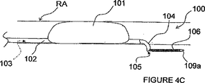
図4A−Dにおいて、ITEV PEFシステム100は、内腔103を有する血管内カテーテル102と、内腔103内を低いプロフィール(輪郭)で送り込まれて内腔103から前進して患者の血管の壁を突き刺すように構成された整形カニューレ104と、カニューレ104の内腔105を通して前進するよう構成された第1のガイドワイヤ電極106とを備えている。カニューレ104は、例えば、形状記憶材料(例えば、ニチノール)又は予め成形された柔軟な弾性材料(例えば、薄壁のステンレススチール)で製造することができる。
4A-D, the
図4A及び4Bの実施形態では、システム100は、更に、血管内に配置するように構成された第2のガイドワイヤ電極108(図4B)も備えている。双極電極対を形成するガイドワイヤ電極106及び108は、遠方端以外の全ての領域において絶縁されるのも任意である。これら電極は、患者の体外に配置されたパルス電界ジェネレータ50(図4B)に電気的に接続される。このジェネレータは、本発明の実施形態では、望ましい電界パラメータをもつPEFを発生するのに使用される。以下に述べるPEF発生電極は、その幾つかの例において、ジェネレータに電気的に接続されるが、ジェネレータは、各実施形態において明確に示されず、又、説明もされないことを理解されたい。
In the embodiment of FIGS. 4A and 4B, the
使用中に、カテーテル102は、図4Aに示すように、腎臓動脈RAへ送り込まれてもよいし、或いはガイドカテーテル又は他の装置を通して、腎臓の静脈へ、又はターゲット神経組織(例えば、腎臓機能に貢献するターゲット神経組織)の付近の他の血管へ送り込まれてもよい。カテーテルは、経皮技術、例えば、経皮大腿骨部動脈通路を経て送り込まれるのが好ましい。整形カニューレ104は、患者の血管内に位置されると、カテーテル102の内腔103の出口を越えて進められ、カニューレ104は、カーブしたプロフィール又は他の角度的プロフィールをとる。カニューレ104は、更に進められると、血管外に配置されるべき患者の血管の壁を突き刺す(即ち、少なくとも外膜内)。第1のガイドワイヤ電極106は、次いで、カニューレの内腔105を通して進められて、第1電極106の非絶縁の遠方領域109aが血管内−血管外の接近路を経て血管外に位置されるようにする。カニューレ104を引っ込め、そしてカテーテル102及びカニューレ104を患者又は処置場所から取り去ることができる。第2のガイドワイヤ電極108の非絶縁の遠方領域109bは、血管内に位置されて(第1電極106の血管外配置の前、その間又はその後に)、第1電極106とで双極電極対を形成する(図4B)。
In use, the
第1電極106は、能動的な電極を構成するのが好ましく、そして第2電極108は、戻り電極を構成するのが好ましい。しかしながら、電極の極性は逆転するのも任意であることを理解されたい。電極106及び108の非絶縁の遠方領域109a−bは、腎臓動脈RAを通る断面平面に沿って実質的に整列されるのも任意である。或いは又、遠方領域109a−bは、長手方向に離間されてもよい。遠方領域109a−bのこのような長手方向離間は、例えば、電極にわたって付与されるパルス電界を腎臓動脈の長手方向次元と良好に整列させ、図3を参照して既に述べたように、非ターゲットの滑らかな筋肉細胞又は他の細胞への作用を制限した状態で腎臓神経の変調を容易にすることができる。
The
第1及び第2の電極106及び108が望ましく位置された状態で、PEFジェネレータ50によって発生されたパルス電界は、電極106及び108を経て送信され、そして電極の非絶縁の遠方領域109a−bにわたって付与される。PEF療法は、腎臓機能に直接的又は間接的に貢献する神経線維に沿って活動を変調する(例えば、腎臓機能に関連した神経線維を除神経する)。これは、例えば、不可逆の電気穿孔、電気融合、神経細胞における壊死及び/又は枯死の誘発、遺伝子発現の変更、シトキン増加作用の変化、及び/又は他の適当なプロセスを経て達成することができる。PEF療法を行った後、ITEV PEFシステム100を患者から取り外し、手順の終了となる。
With the first and
ITEV PEFシステム100を使用するPEF療法は、CHF、高血圧症、腎臓疾病及び/又は他の心臓−腎臓疾病の臨床学的兆候を、数か月の期間、潜在的には、6カ月まで又はそれ以上の期間にわたり緩和することが予想される。この期間は、身体が病を癒せるに充分なものであり、例えば、この期間は、急性心筋梗塞の後にCHFが始まるおそれを減少し、その後の再処置の必要性を緩和する。或いは又、兆候が再発したときに又は規則的にスケジュールされた間隔で、患者は、療法を繰り返すために医師を再訪問してもよい。
PEF therapy using the
ターゲット神経線維を除神経するか又はその他変調するために、ITEV PEFシステム100は、このような除神経又は変調を誘起するに充分な強度又は大きさの電界を線維にわたって発生しなければならない。血管内PETシステムを使用するときには、PEF電極の配列及び位置付け、並びに患者の生理学的状態に基づいて、ターゲット神経線維において充分な大きさの電界強度を達成するに必要な印加電圧は、又、滑らかな筋肉細胞及び/又は血管壁のような非ターゲット組織に望ましからぬ持続的な傷を誘起するに足る大きさにもなり得る。血管内−血管外の接近路を経て電極106を血管外に位置させることは、同様の間隔及びサイズの電極を伴う血管内のみの装置を使用するときに要求される印加電圧に比して、PEF治療を経て除神経又は変調(例えば、腎臓除神経又は変調)を行うのに必要な印加電圧を減少させる。特に、ターゲット神経線維に密接接近して電極106を血管外配置することは、ターゲット神経線維の付近へのピーク誘起電界の局所化を高めることが予想される。
In order to denervate or otherwise modulate the target nerve fiber, the
図4Cに見られるように、カテーテル102は、患者の血管内にこのカテーテル102を安定化させる膨張可能な素子101(例えば、膨らますことのできるバルーン(風船))を含むのも任意である。この膨張可能な素子101は、更に、カニューレ104で血管壁を突き刺して、第1電極106を血管外の位置に配置させるのを容易にする。図4Dに見られるように、第1電極106は、離間された双極電極対107a及び107bを含み、血管内の第2電極108の必要性をなくすことができる。PEF治療は、双極電極対107a−bにわたって血管外で行われる。
As seen in FIG. 4C, the
血管外の第2電極106を仮想電極と置き換えるのも任意である。例えば、カニューレ104を通して血管外のスペースへ導電性の食塩水を注入してもよい。導電性の食塩水は、血管の全周又はその一部分を取り巻く仮想電極を構成し、血管内電極108と双極形態で使用することができる。
It is optional to replace the
図4A−DのITEV PEFシステムの実施例は、血管内の第2電極108を、PEFジェネレータ50に結合され且つ患者の体外に取り付けられた接地パッドと置き換えることにより、単極形態で使用されるのも任意である。図5は、膨張可能な素子114を有し、この膨張可能な素子に1つ以上のニードル状ITEV電極116が結合されたカテーテル112を備えた別の単極のITEV PEFシステム110を示している。複数のニードル電極116が設けられるときには、それらが、膨張可能な素子114のまわりで/それに沿って周囲方向に及び/又は長手方向に離間される。システム110は、更に、患者の体外に沿って患者の皮膚S(例えば、患者の脇腹、背中又は大腿部)に取り付けられ且つPEFジェネレータ50に戻り電極として結合された接地パッド120を備えている。この接地パッド120は、ITEV電極116の真横に配置して、患者の血管に沿って(例えば、腎臓動脈RAに沿って)PEF治療を指令するのも任意である。
The embodiment of the ITEV PEF system of FIGS. 4A-D is used in a monopolar configuration by replacing the
膨張可能な素子114は、低いプロフィール形状で血管内をターゲット位置へ送り込む(そしてそこから引っ込める)と共に、ターゲット位置において膨張された配備構成へと膨張するように構成された部材又は構造体を含む。膨張可能な素子114は、例えば、膨らまし得るバルーン、膨張可能なかご(ケージ)又はおり(バスケット)、或いは他の膨張可能な構造体で構成される。図5に見られるように、膨張可能な素子114が膨張すると、ITEV電極116(1つ又は複数)が腎臓動脈RAの壁に突き刺さり、血管内の位置から血管外の位置へ移動する。ITEV電極116が血管外に位置されてPEFジェネレータ50に結合された状態では、ITEV電極は、単極のPEF療法において能動的な電極として付勢され、体外の接地パッド120は、戻り電極として働く。
図6A−Cを参照し、血管外に位置される第1電極と、血管内に位置される第2電極とを備えたITEV PEFシステム110の別の実施形態を説明する。図6A−Cにおいて、ITEV PEFシステム110は、この場合も、膨張可能な素子114を有していて、1つ以上のITEV電極116がこの膨張可能な素子に結合されて血管内−血管外に送り込むよう構成されたカテーテル112を備えている。システム110は、更に、血管内に配置される血管内の第2電極118を備えている。図6Aにおいて、第2電極118は、カテーテル112の内腔に位置されたガイドワイヤ電極で構成される。このガイドワイヤ電極118は、PEFジェネレータ50に結合され、そしてカテーテル112の遠方に位置する遠方領域以外の領域で絶縁されている。図6Bにおいて、第2電極118は、膨張可能な素子114の遠方でカテーテル112のシャフトに結合される。図6Cにおいて、第2電極118は、膨張可能な素子114の近方でカテーテル112のシャフトに結合される。使用中に、ITEV電極116(1つ又は複数)は、能動的な電極を構成し、そして第2電極118は、戻り電極を構成するが、その逆でもよい。第2電極118は、図2及び3を参照して既に述べたように、PEF療法を患者の血管の長手軸に整列するために、ITEV電極116に対して長手方向に離間されるのも任意である。第2電極118は、例えば、ワイヤを巻いたコイルで作られてもよい。比較的長い電極を使用するときには、巻かれたコイルは、カテーテル112が望ましい柔軟性を維持できるようにする。
With reference to FIGS. 6A-C, another embodiment of the
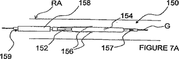
図7A及び7Bを参照して、血管外に位置される第1電極と、血管内に位置される第2電極とを有する双極電極対を経てパルス電界神経変調を行うための付加的な方法及び装置を説明する。図7A及び7Bは、より詳細には、カテーテル152と、膨らまし得るバルーン又は膨張可能なワイヤかごで構成される膨張可能な素子154とを備えたITEV PEFシステム150を示している。システム150は、更に、膨張可能な素子154の近方に示されたカテーテル152に結合された1つ以上のITEVニードル電極156と、膨張可能な素子154の遠方でカテーテル152のシャフトに結合されて示された戻り電極157とを備えている。更に、システムは、経皮的に前進させ及び/又は引っ込めるためにカテーテル152が位置される内腔159を有する保護シース158を備えている。
With reference to FIGS. 7A and 7B, an additional method for performing pulsed field neuromodulation via a bipolar electrode pair having a first electrode located outside the blood vessel and a second electrode located within the blood vessel, and The apparatus will be described. FIGS. 7A and 7B more particularly show an
図7A及び7Bにおいて、ITEV電極156の遠方領域は、横方向に延びるが、膨張可能な素子154の少なくとも一部分に接続されない。これは、膨張可能な素子に直結されたITEV電極を有する図4−6の上述したITEV PEFシステムとは対照的である。ITEV電極156を膨張可能な素子154から分離することにより、図7A及び7Bのシステム150は、製造を簡単にし、及び/又は膨張の信頼性を向上させる。
In FIGS. 7A and 7B, the far region of the
図7Aに見られるように、カテーテル152及び保護シース158は、患者の血管内の位置へと(例えば、腎臓動脈RA内でガイドワイヤG上を)進めることができる。しかるべき位置に来ると、シース158がカテーテル152に対して引っ込められ、及び/又はカテーテル152がシース158に対して前進され、膨張可能な素子154、ITEV電極156、及び戻り電極157が保護シース158の遠方に位置されるようになる。図7Bに見られるように、次いで、膨張可能な素子154が膨張されて、ITEVニードル電極156が血管壁に穴をあけ、ITEV接近路を経て血管外に位置される。電極156が血管外に位置されると、PEF療法がITEV電極156と戻り電極157との間で進められる。PEF療法は、例えば、腎臓機能に貢献する神経線維を変調し及び/又は除神経することができる。PEF療法が完了すると、膨張可能な素子154がつぶれ、シース158がカテーテル152に対して前進され、ITEV電極156が血管壁から除去される。次いで、システム150が患者から取り外されて、手順が完了となる。
As seen in FIG. 7A, the
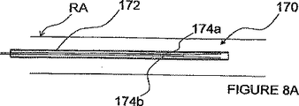
図8A−Cを参照し、各対の両電極が血管内−血管外接近路を経て血管外に位置されるような1つ以上の双極電極対を使用してパルス電界神経変調を行うための方法及び装置を説明する。このようなITEV PEFシステム170の一例は、カテーテル又はシース172を備え、このシース内の血管内位置へ前進するように構成された整形ITEV双極ニードル電極174a及び174bを有している。これら電極174a−bは、形状記憶特性を有し(例えば、ニチノールのような形状記憶合金で製造され)、そしてその遠方領域以外の位置で絶縁されてもよい。図8Bに見られるように、電極174a−bがシース172の遠方の位置へ前進されると(例えば、シースを引っ込めることにより)、電極174a−bは、それらの予め成形された形状をとり、そして患者の血管、ここでは、腎臓動脈RAの壁に突き刺さり、電極174a−bの遠方領域がITEV接近路を経て血管外に位置されるようになる。明らかなように、電極174a及び174bは、PEF療法を患者の血管の長手方向次元に良好に整列するために互いに長手方向に離間されてもよい。更に、図示された電極は、半径方向に約180°離間されているが、これら電極は、望ましい半径方向分離で(又は分離なしに)離間されてもよいことを理解されたい。
Referring to FIGS. 8A-C, for performing pulsed field nerve modulation using one or more bipolar electrode pairs such that each pair of electrodes is positioned extravascularly via an intravascular-extravascular approach. A method and apparatus are described. An example of such an
図8Cは、長手方向に離間されたITEV電極の複数の対を備えたITEV PEFシステム170の別の例を示す。このシステム170は、例えば、第1の双極電極対174a及び174bと、第2の双極電極対174a’及び174b’とを含むことができる。他の実施例では、必要に応じて、異なる周囲方向位置における又は異なる長手方向間隔をもつ双極電極の付加的な対を使用してもよい。
FIG. 8C shows another example of an
適切に位置されると、PEF療法を電極174にわたって行い、望ましい神経変調を達成することができる。PEF療法が完了すると、ニードル電極174をシース172に対して引っ込め、及び/又はシース172を電極174に対して進ませて、電極を患者の血管壁から取り去り、シース内に拘束された引っ込め構成へとうまく戻すことができる。次いで、ITEV PEFシステム170を患者から取り去り、手順を完了することができる。
When properly positioned, PEF therapy can be performed across electrode 174 to achieve the desired neuromodulation. When PEF therapy is complete, the needle electrode 174 is retracted relative to the
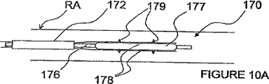
図9を参照して、膨張可能な素子177を有するカテーテル176を備えたITEV PEFシステム170の別の実施形態を説明する。膨張可能な素子177は、膨張されたときに、血管壁を横切るように電極174を向け又は押し付けるガイドとして働く。より詳細には、膨張可能な素子177は、これが膨張された後にこの膨張可能な素子177に沿って電極174を前進することにより血管壁に電極174を貫通させることができる。或いは又、膨張可能な素子177は、この膨張可能な素子177が低いプロフィール形状である間にこの膨張可能な素子177の上に電極174を前進させ、次いで、膨張可能な素子177を膨張させて血管壁を横切って電極174を押し付けることにより、血管壁を横切って電極174を押し付けることができる。
With reference to FIG. 9, another embodiment of an
図10A−Fは、双極電極の複数の対を備えたITEV PEFシステム170の更に別の実施形態を示す。図10A及び10Bでは、ITEV電極174がITEV電極キャリア178に置き換えられている。各ITEV電極キャリア178は、複数の電極179を含む。例えば、各電極キャリア178は、一対の電気的に分離された双極電極179を含んでもよい。或いは又、各キャリア178は、共通の極性の複数の電極179を含んでもよい。電極179は、患者の血管壁を貫通するための尖鋭な点、ピン、又は他の立ち上った特徴部を含む。図10Aに見られるように、電極179は、例えば、シース172を通して又はシース172内で、低いプロフィール形状で、刺激場所へ送り込むことができる。次いで、電極179は、図10Bの場合のように、膨張可能な素子177を膨張させることにより、ITEV接近路を経て、血管外に位置させることができる。
10A-F illustrate yet another embodiment of an
図10C及び10Dに見られるように、電極キャリア178は、カラー175において膨張可能な素子177の遠方でカテーテル176に結合されるのも任意である。カラー175は、カテーテル176にスライド可能に取り付けられてもよいし、及び又は長手方向に拘束されてもよい。キャリアをカテーテルに取り付けることで予想される利益として、ITEV接近路を経て電極179を血管外に位置させることが良好に制御される。
As seen in FIGS. 10C and 10D, the
図10Eに見られるように、電極キャリア178は、膨張可能な素子177の周りで螺旋状にされるのも任意である。キャリア178は、周囲方向のPEF療法を容易にするために複数の周囲方向位置に配置された多数の電極179を含むのも任意である。電極キャリア178は、互いに電気的に分離されるのが好ましい。例えば、キャリア178は、電極179を除く全ての領域において絶縁することができる。
As seen in FIG. 10E, the
図10Fに見られるように、システム170は、膨張可能な素子177の周りで螺旋状にされる単一の電極キャリア178を含むのも任意である。一体的キャリアに沿った複数の電極は、共通の極性のものでもよいし、及び/又は互いに電気的に分離されそして双極電極対を形成するように異なる極性のものでもよい。電極179は、必要に応じて、複数の周囲方向位置に配置されてもよい。
As seen in FIG. 10F, the
図11A−Cは、電極179の血管外配置の前に電極179の血管内送り込みを容易にする安全特徴を備えたITEV PEFシステム170の付加的な実施例を示す。図11A−Cの実施形態では、電極179は、各電極キャリア178に対する電極179の回転を容易にするように、電極キャリア178に結合される。例えば、電極179は、回転支持面を構成するピボット180においてキャリア178に結合される。更に、電極179は、延長部182も備え、これは、膨張可能な素子177と協働して、電極179を、低い送り込み及び引っ込めプロフィールと、電極のITEV送り込みに適した膨張プロフィールとの間で選択的に回転させる。電極179は、例えば、スプリングメカニズムを経て低いプロフィールに向かってバイアスされるのも任意である。この低いプロフィールは、処置場所において電極をITEV配置する前に血管組織に偶発的に穴をあけるおそれを減少する安全特徴として働く。
FIGS. 11A-C illustrate additional embodiments of the
図11Aに見られるように、電極179は、血管内処置場所へ送り込まれる間に(例えば、シース172を通して又はその中を)、電極キャリア178の付近又はそれに対してフラットに横たわる。電極179は、その送り込み中に、膨張可能な素子177の近方に位置される。血管内に位置されると、電極179が膨張されて、膨張可能な素子177を電極キャリア178に対して引っ込めることによりその尖端が半径方向外方を向くようにする。図11Bに見られるように、膨張可能な素子177を引っ込めると、それが電極179の延長部182に係合し、電極179がピボット180の周りで回転して、電極179のITEV送り込みに適した膨張形状になる。次いで、膨張可能な素子177が膨張され、電極179は、図11Cのように、ITEV接近路を経て血管壁を貫通するように強制される。次いで、希望するように、ITEV PEF療法を進めることができる。治療が完了すると、膨張可能な素子177及び電極179は、患者から引っ込めるための低いプロフィール形状へ戻される。
As seen in FIG. 11A, the
図12を参照して、血管内−血管外接近路を経て血管外に配置された少なくとも1つの角度的に整列され長手方向に離間された双極電極対を経てパルス電界神経変調を行うための方法及び装置を説明する。より詳細には、図12は、少なくとも一対の長手方向に離間された双極ニードル電極206a及び206bをもつ膨張可能な素子204を有するカテーテル202を備えたITEV PEFシステム200の実施例を示す。ニードル電極206a−bは、膨張可能な素子に沿った実質的に同じ角度位置に配置される(図12において、システムは、説明上、個別の周囲方向位置に配置された2対の長手方向に離間され角度的に整列された双極電極206a−bを備えている)。長手方向に離間された双極電極206a−bの角度的な整列は、上述したように、PEF療法をターゲット神経線維の長手方向軸に整列させることができる。ニードル電極206の双極対は、望ましい長手方向間隔を含んでもよく、例えば、電極は、約0.5ないし10mmの範囲の間隔を含む。
Referring to FIG. 12, a method for performing pulsed field neuromodulation via at least one angularly aligned and longitudinally spaced bipolar electrode pair placed extravascularly via an intravascular-extravascular approach. And the apparatus will be described. More specifically, FIG. 12 shows an example of an
ITEV PEFシステム200は、良く知られた経皮技術を使用して、腎臓動脈RA内の場所のような血管内処置場所へ送り込むことができる。例えば、システム200は、カテーテル202の内腔203内に位置するガイドワイヤG上を前進され、又、カテーテル202は、ガイドカテーテル又はシース210を通して/その中を前進される。処置場所に位置されると、膨張素子204が膨張されて、血管壁を横切って双極ニードル電極206を押しやり、電極206の端がITEV接近路を経て血管外に位置されるようにする。膨張素子204は、例えば、(a)バルーンを膨らまし、(b)シース210の遠方に素子204を位置させた後にかご又はおりを自己膨張させ、及び/又は(c)種々のプッシュ/プッシュ及び/又は引っ張り/圧縮技術を経てかご又はおりを機械的に膨張させることにより、膨張することができる。
The
ITEV技術を使用して電極206を位置させることで、電極は、腎臓機能に貢献するターゲット神経線維に密接に接近して配置される。上述したように、腎臓神経は、腎臓動脈の外膜、及び/又は腎臓動脈を直に取り巻く組織に位置される。電極のこのようなITEV位置付け、及び双極電極対(1つ又は複数)の選択された角度整列は、血管内に位置された電極を備えたPEFシステムに比して、望ましい神経変調を達成するに必要なエネルギー要件を緩和することができる。 By positioning the electrode 206 using ITEV technology, the electrode is placed in close proximity to target nerve fibers that contribute to kidney function. As described above, the renal nerve is located in the outer membrane of the renal artery and / or in the tissue that directly surrounds the renal artery. Such ITEV positioning of the electrodes and the selected angular alignment of the bipolar electrode pair (s) is to achieve the desired neuromodulation as compared to a PEF system with electrodes positioned within the blood vessel. The necessary energy requirements can be relaxed.
電極206は、出血したり血管壁を傷付けたりする等の甚だしいおそれなく、腎臓動脈RAの壁を安全に横切るに足るほど小さな直径であるのが好ましい。例えば、電極は、約23ゲージ未満の直径である。更に、電極は、内実でもよいし、或いは1つ以上の内腔を含むものでもよい。内腔(1つ又は複数)を伴うときには、ニードル電極は、望ましい神経変調作用を向上させる薬剤を注ぐか(例えば、塩水の注入を使用して、PEF療法中に導電率を局所的に向上させることができる)、又は保護作用を与える薬剤を注ぐ(例えば、冷却材を注入して非ターゲット組織を保護することができる)ように構成できる。 The electrode 206 is preferably small in diameter so that it can safely cross the wall of the renal artery RA without the risk of bleeding or damaging the vessel wall. For example, the electrodes are less than about 23 gauge in diameter. Further, the electrode may be solid or may include one or more lumens. When accompanied by the lumen (s), the needle electrode is injected with an agent that improves the desired neuromodulation effect (eg, using saline infusion to improve conductivity locally during PEF therapy) Or can be configured to pour a protective agent (eg, coolant can be injected to protect non-target tissue).
又、ニードル電極206は、それらの全長に沿って導電性でもよいし、又はそれらの長さの少なくとも一部分に沿って絶縁されてもよい。例えば、ニードル電極206は、それらの遠方端以外の位置で絶縁することができる。電極206の長さの一部分に沿った絶縁は、非ターゲット組織、例えば、患者の血管の内膜又は中膜へのパルス電界療法の望ましからぬ実行を減少することができる。このような絶縁電極は、電極のITEV位置付け中に少なくとも血管の外膜内の位置において電極の非絶縁部分を血管外に配置するのに充分な長さを含むのが好ましい。 The needle electrodes 206 may also be conductive along their entire length or may be insulated along at least a portion of their length. For example, the needle electrodes 206 can be insulated at locations other than their distal ends. Insulation along a portion of the length of the electrode 206 can reduce the undesirable performance of pulsed electrotherapy to non-target tissue, eg, the intima or media of a patient's blood vessel. Such an insulated electrode preferably includes a length sufficient to place the non-insulated portion of the electrode outside the blood vessel at least within the outer membrane of the blood vessel during ITEV positioning of the electrode.
図13A−Dを参照して、各電極対が異なる周囲方向位置に配置された複数対の角度的に整列され長手方向に離間されたITEV双極電極を経てターゲット神経線維の周囲方向パルス電界変調を行う方法及び装置を説明する。図13A−Dは、図12の断面線A−Aに沿ったITEV PEFシステム200の幾つかの実施例を示す。図13Aにおいて、ITEV PEFシステム200は、図12と同様に、周囲方向に約180°離れて位置された2対の角度的に整列され長手方向に離間された双極電極206を備えている。図13Bにおいて、システム200は、約120°離間された3対のこのような双極電極を備えている。図13Cにおいて、システム200は、ほぼ90°離間された4つの対を備え、そして図13Dにおいて、システム200は、約45°離間された8つの対を備えている。明らかなように、いかなる望ましい数の電極対が設けられてもよい。更に、図13A−Dに示す電極対は、周辺方向に等しく離間されるが、他の希望の不等の周囲方向間隔を含む他の希望の間隔で周囲方向に離間されてもよい。
Referring to FIGS. 13A-D, circumferential pulse electric field modulation of a target nerve fiber is performed through multiple pairs of angularly aligned and longitudinally spaced ITEV bipolar electrodes, with each electrode pair positioned at a different circumferential position. The method and apparatus to perform is described. 13A-D illustrate several embodiments of the
図13A−Dに電界線Lで示されたように、各双極電極対にわたるPEF療法の実行により影響される組織領域、例えば、希望の神経変調を経験する組織領域は、処置場所の狭い周囲方向セグメントに限定される。双極ITEV電極対206の複数対を設けることで、より多くの周囲処置が与えられる。図13Dに見られるように、ITEV双極電極206の付加的な対を追加すると、最終的に、周囲方向に影響されるセグメントが重畳され、これにより、全周処置が与えられる。あるケースでは、全周処置を与えることが望まれ、一方、他のケースでは、全周未満の処置を与えることが望まれる。医者は、希望レベルの周囲処置を与えることもでき、及び/又は希望の数の周囲方向に離間された双極電極対を利用することができる。患者の血管の長手方向セグメントに沿った周囲方向PEF療法は、膨張素子204をつぶし、カテーテル202をその長手方向軸の周りで希望の量だけ回転し、次いで、膨張素子204を再び膨張させて、電極対206を、患者の血管の別の周囲方向長手セグメントの処置のために血管外に配置し直すことにより、達成することができる。このプロセスは、必要に応じて、単一の長手方向位置において繰り返すことができる。
As shown by electric field lines L in FIGS. 13A-D, a tissue region that is affected by the performance of PEF therapy across each bipolar electrode pair, eg, a tissue region experiencing the desired neuromodulation, is a narrow circumferential direction of the treatment site. Limited to segments. By providing multiple pairs of bipolar ITEV electrode pairs 206, more ambient treatment is provided. As seen in FIG. 13D, the addition of an additional pair of ITEV bipolar electrodes 206 ultimately superimposes the circumferentially affected segments, thereby providing a full circumference treatment. In some cases it may be desirable to provide a full circumference treatment, while in other cases it may be desirable to provide less than full circumference treatment. The physician may provide the desired level of ambient treatment and / or may utilize a desired number of circumferentially spaced bipolar electrode pairs. Circumferential PEF therapy along the longitudinal segment of the patient's blood vessel collapses the
図14A及び14Bは、外部シース304、ガイドワイヤチューブ306、及び無傷性ノーズコーン308を有するカテーテル302を備えた付加的なITEV PEFシステム300を示す。ガイドワイヤチューブ302は、無傷性ノーズコーン308の内腔309に結合され、そしてそれを通して延び又はそれと連通する。又、システム300は、遠方領域においてノーズコーン308に結合された多数の近方配向のITEVニードル電極310と、ガイドワイヤチューブ302の周りに同軸的に配置されたプッシュチューブ312も備えている。プッシュチューブ312は、比較的剛性があり及び/又は放射線不透過のフレア付きチップ314を有するのも任意である。電極310は、ガイドワイヤチューブ302と共に又はその中に形成された電気的接点を経て(例えば、ガイドワイヤチューブの外径上又はその付近の金属編組、コイル又はワイヤを経て)PEFジェネレータ50に結合することができる。電極310は、PEF療法の実行を容易にするためにこれら電気的接点に物理的に接触することができ。幾つかの実施形態では、フレア付きチップ314は、図14Bのように、電極に接触した際に回路を完成する。
FIGS. 14A and 14B show an additional
図14Aは、電極310がシース304内に位置された低い送り込み及び引っ込め構成でシステム300を示している。処理場所に血管内配置されると、シース304が引っ込められ、及び/又はガイドワイヤチューブ302が前進され、電極310がシース304から取り外される。電極310は、変形に抵抗し且つ変形時に回復力を加える弾力性材料で製造されるのが好ましい。更に、電極310は、この電極310を図14Aに示す低いプロフィールにバイアスするようにノーズコーン308に結合されるのが好ましい。
FIG. 14A shows the
図14Bに示すように、カテーテル302が処理場所(例えば、腎臓動脈RA内)に位置されると、プッシュチューブ312がガイドワイヤチューブ302に対して前進され、フレア付きチップ314が電極310に係合して、これを半径方向外方に弾力で変形させる。電極310は、血管に突き刺さり、電極の尖端をITEV接近路を経て血管外に位置させる。カテーテル302は、電極310の変形後に引っ込められ、電極を患者の血管に係合させて、電極を血管外に配置するのも任意である。次いで、PEF療法を進行させ、望ましい神経変調を達成することができる。処置の完了時に、プッシュチューブ312がガイドワイヤチューブ306及び電極310に対して引っ込められる。ガイドワイヤチューブ306は、若干前進されて、電極310を血管壁から解放する。電極310により与えられる回復力で、電極310を低い休止プロフィールに戻す。次いで、シース304がガイドワイヤチューブ306に対して前進され、ニードル電極310は、患者から引っ込めて取り外すために、図16Aのように、もう一度、シース304内に位置される。
As shown in FIG. 14B, when the
図14A及び14Bの装置の付加的な又は別の実施形態において、ニードル電極310は、ニードル電極を前進するときに通るニードルハウジンに置き換えることができる。このニードルハウジンは、血管壁に接触するように膨張され、次いで、ニードル電極が血管壁を横切って前進される。このような前進は、種々の機械的手段を経て達成することができる。例えば、ガイドワイヤチューブ、ノーズコーン及び/又はニードルハウジンに対する特定の位置を越えてプッシュチューブを前進すると、ニードルを進めるスプリング負荷部材を解放することができる。
In additional or alternative embodiments of the apparatus of FIGS. 14A and 14B, the
図14C及び14Dは、1つ以上の長手方向に離間された双極電極対を含むITEV PEFシステム300の別の実施形態を示す。図14C及び14Dにおいて、ニードル電極310aはノーズコーン308に結合され、そしてニードル電極310bは、第1のプッシュチューブ312aの第1のフレア付きチップ314aの近方領域に結合される。システム300は、更に、第2のフレア付きチップ314bを有する第2のプッシュチューブ312bも備えている。第2のプッシュチューブ312bは、第1のプッシュチューブ312aの周りに同軸的に配置される。
14C and 14D show another embodiment of an
電極310a及び310bは、1つ以上の長手方向に離間された双極電極対を形成する。例えば、電極310aは、能動的な電極を構成し、そして電極310bは、戻り電極を構成し、或いはその逆でもよい。図14Cに見られるように、電極は、シース304内に送り込まれる。処置場所に位置されると、シース304が引き出され、そして電極310が、図14Dのように、ITEV接近路を経て血管外に位置される。より詳細には、第1のプッシュチューブ312aは、ガイドワイヤチューブ306に対して前進され、第1のフレア付きチップ314aがニードル電極310aに当たってそれを変形させる。これは、血管壁を横切って電極310aを押しやる。同様に、第2のプッシュチューブ312bは、第1のプッシュチューブ312aに対して前進され、第2のフレア付きチップ314bがニードル電極310bに当たってそれを変形させる。このメカニズムは、血管壁を横切って電極310bを押しやる。図14C及び14Dの実施形態では、フレア付きチップ314は、電極310を変形するために徐々に移行する遠方プロフィールを含む。
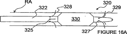
図15A−Cは、(a)近方サイドポート325で終了する複数の近方電極内腔324と、遠方サイドポート327で終了する複数の遠方電極326と、(c)ガイドワイヤ内腔323とを有するカテーテル322を備えた別のITEV PEFシステム320の実施例を示す。このカテーテル322は、同じ数の近方及び遠方電極内腔を含むのが好ましい。又、システム320は、近方電極内腔324を通して前進される近方ニードル電極328と、遠方電極内腔326を通して前進されるニードル電極329も備えている。
FIGS. 15A-C show: (a) a plurality of
図15Aに示すように、カテーテル322は、ガイドワイヤ321上を、内腔323を経て、患者の血管内の処置場所へ(例えば、患者の腎臓動脈RA内の処置場所へ)前進される。血管内の送り込み中に、電極328及び329は、それらの非絶縁及び先鋭化遠方領域が内腔324及び326内に各々位置されるように位置付けられる。処置場所に位置されると、医師は、患者の体外に位置する近方領域を経て電極を前進させる。図15Bに見られるように、このような前進は、電極326及び329の遠方領域をサイドポート325及び327から各々退出させると共に、患者の血管壁を突き刺して、これらの電極がITEV接近路を経て血管外に位置されるようにする。
As shown in FIG. 15A, the
近方電極328は、能動的電極としてPETジェネレータ50に接続することができ、そして遠方電極329は、戻り電極として働くことができる。このように、近方及び遠方電極は、PEF療法を患者の血管の長手軸又は方向に整列させる双極電極対を形成する。明らかなように、遠方電極329が能動的電極を構成し、そして近方電極328が戻り電極を構成してもよい。更に、近方及び/又は遠方電極は、能動的及び戻りの両電極を構成してもよい。必要に応じて、能動的及び戻り電極の組合せを使用してもよい。
The
電極328及び329が血管外に位置されると、PEF療法を進めて、望ましい神経変調を達成することができる。PEF療法が終了すると、電極が内腔324及び326内で引っ込められる。次いで、カテーテル322及びガイドワイヤ321を患者から取り外して、手順を完了することができる。それに加えて又はそれとは別に、別の処理場所でPEF療法を行うようにカテーテルを位置し直すことができる。
Once
図16A及び16Bは、ITEV PEFシステム320の別の実施形態を示す。図16Aにおいて、システム320のカテーテル322は、更に、膨らまし得るバルーン或いは膨張可能なかご又はおりで構成される膨張可能なセンタリング素子330を備えている。使用中に、センタリング素子330は、ニードル電極328及び329を配備する前に膨張されて、患者の血管内で(例えば、腎臓動脈RA内で)カテーテル322をセンタリングする。カテーテル322をセンタリングすることで、患者の血管内の希望の深さ/血管外への全てのニードル電極の送り込み(例えば、同じ深さへの全てのニードル電極の送り込み)を容易にすることが予想される。
FIGS. 16A and 16B show another embodiment of the
図16Aにおいて、図示されたセンタリング素子330は、近方サイドポート325と遠方サイドポート327との間に位置され、即ち近方及び遠方電極の送り込み位置の間に位置される。しかしながら、センタリング素子330は、それに加えて、又はそれとは別に、カテーテル322の長さに沿った異なる位置又は多数の位置(例えば、サイドポート325の近方の位置及び/又はサイドポート327の遠方の位置)に位置されてもよい。図16Bにおいて、システム320は、説明上、近方のサイドポート325の近方に位置された第1のセンタリング素子330aと、遠方のサイドポート327の遠方に位置された第2のセンタリング素子330bとを備えている。
In FIG. 16A, the illustrated centering
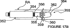
図17A−Eを参照して、1つ以上のハイポチューブを使用するITEV PEFシステム350を説明する。図17A及び17Bの実施形態において、ITEV PEFシステム350は、外側シース354と、外側シャフト356と、複数の遠方延長部359をもつハイポチューブ358と、ガイドブロック362をもつ内側シャフト360とを有するカテーテル352を備えている。内側シャフト360は、無傷性チップ364で終了し、そして内側シャフト及び無傷性チップを通してガイドワイヤ内腔が延びているのが好ましい。ハイポチューブ358は、その近方側では、外側シャフト356に接続され、そして外側シャフト356は、内側シャフト360上に同軸的に位置される。
With reference to FIGS. 17A-E, an
ハイポチューブ358は、その一部分を切削することにより作られた延長部359を有することができる。ハイポチューブ358は、金属合金又は白金のような導電性材料から作ることもできるし、或いはハイポチューブは、比較的非導電性の材料で構成されてもよい。延長部359は、選択的に絶縁及び/又は非絶縁にされ、そしてPEFジェネレータ50に電気的に接続されて、1つ以上の延長電極を形成することができる。延長電極は、例えば、金属堆積プロセスを経て、ハイポチューブ及びその延長部にエッチングされてもよい。エネルギー供給のための電気接点が、絶縁延長部359の尖端に露出されるか、或いは非絶縁接点が延長部の全長又はその一部分にわたって延びてもよい。更に、ハイポチューブが導電性材料で作られたときには、ハイポチューブ358全体で電極を構成してもよい。
The
延長電極(1つ又は複数)359は、共通の極性でもよいし異なる極性でもよい。異なる極性のときには、PEF療法が双極形態で電極にわたって行われる。共通の極性のときには、電極は、例えば、外部の接地パッドと共に単極形態で使用される。或いは又、カテーテル352は、逆極性の1つ以上の付加的な電極をその長さに沿って含むのも任意であり、これは、ハイポチューブ358の延長電極359と共に双極形態で使用される。一実施形態において、外側シャフト356は、延長電極(1つ又は複数)を有する少なくとも第2のハイポチューブをその長さに沿って含み、この延長電極は、逆極性の付加的な電極(1つ又は複数)として働き、PEF療法を施すために離間された双極電極対(1つ又は複数)を形成するのに使用される。
The extension electrode (s) 359 may have a common polarity or different polarities. When of different polarity, PEF therapy is performed across the electrodes in a bipolar configuration. When in common polarity, the electrode is used, for example, in monopolar form with an external ground pad. Alternatively, the
図17Aに見られるように、カテーテル352は、良く知られた経皮技術を使用して(例えば、ガイドカテーテルを通して)患者の血管内の処置場所、例えば、腎臓動脈RA内の処置場所へ進められる。適切に位置されると、外側シース354は、ハイポチューブ358を露出するように引っ込められ、次いで、外側シャフト356は、ガイドブロック362に対して延長部359を駆動するように内側シャフト360に対して進められる。図17Bに見られるように、ガイドブロック362は、外側シャフト354が内側シャフト360に対して前進されるときに延長部359を弾力的又は可塑的に次第に変形させるテーパー付けされた移行部を形成する。この変形は、延長部359を半径方向外方に向けて、延長電極をデトーン(detone)する。外側シャフトを前進し続けると、延長電極が血管壁を貫通し、ITEV接近路を経て血管外に位置されるようにする。延長電極359が血管外に位置された状態で、PEF療法が行われる。
As seen in FIG. 17A, the
PEF療法の完了時に、延長部359は、システム350を患者から回収するために、外側シャフト356に対してもう一度つぶされる。延長部359の変形が弾性変形の場合には、外側シャフト356を腎臓動脈RAの壁に対して引っ込めて、延長部を壁から取り去ることができる。次いで、延長部359は、図17Aの休止構成へ戻される。変形が可塑的である場合には、延長部359は、例えば、外側シース354又はガイドカテーテルを外側シャフト356上で前進させてシース354が延長部359のベースに当たるようにすることで、つぶすことができる。次いで、シース354が固定保持されるか又は外側シャフトに対して進められる間に外側シャフト356を引っ込めて、延長部359をシース354内でつぶし、システム350を患者から回収することができる。
Upon completion of PEF therapy,
図17C及び17Dに見られるように、ITEV PEFシステム350は、ITEV電極の1つ以上の長手方向離間対を備えるのも任意である。図17C及び17Dにおいて、ハイポチューブ358は、遠方延長部359a及び近方延長部359bを含む。遠方延長部359aは、上述したように、血管外に配備される。近方延長部359bのITEV配備については、システム350は、近方延長部359bを変形するための遠方配向ガイドブロック362’を有する近方プッシュチューブ355を更に備えている。プッシュチューブ355は、外側シャフト356上で、外側シース354内に同軸的に配置される。図17Dに見られるように、プッシュチューブ355は、外側シャフト356に対して前進されて、近方延長部359bを変形すると共に、ITEV接近路を経て延長電極を血管外に位置させる。ハイポチューブ358の近方及び遠方延長電極は、1つ以上の長手方向に離間された双極電極対を形成する。
As seen in FIGS. 17C and 17D, the
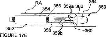
図17Eにおいて、ITEV PEFシステム350は、この場合も、遠方延長部359a及び近方延長部359bを含む。しかしながら、図17Eの実施形態では、近方及び遠方延長部が全て遠方配向であり、遠方延長部359aは、近方延長部359bより長さが長い。これら延長部の血管外配置の間に、遠方延長部359aのこの付加的な長さは、遠方延長部が、近方延長部359bよりも遠方で患者の血管壁を突き刺すようにさせる。このように、近方及び遠方延長部359a−bは、血管外に配備されるときに互いに長手方向に離間される。血管外PEF療法が完了した後に、近方及び遠方延長部359a−bの遠方配向は、それら延長部をつぶして回収するのを容易にする。シース354が固定保持されるか又は外側シャフトに対して進められる間に外側シャフト356を引っ込めて、延長部359a−bをシース354内でつぶし、システム350を患者から回収することができる。
In FIG. 17E, the
図17A−Eに示すITEVシステム350の幾つかの例は、ガイドブロック362を経てのITEV延長電極359の配備を示しているが、種々様々な別の技術により電極を配備してもよいことを理解されたい。例えば、プルワイヤのようなプッシュ/プルメカニズムを使用して、ハイポチューブ延長部を変形してもよい。或いは又、圧力又は真空チャンネルを使用してもよい。又、単一の配備メカニズムにより、ハイポチューブ及び/又はハイポチューブ延長電極のアレイを配備するのも任意である。
Although some examples of the
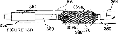
図18A−Dを参照して、ITEV PEFシステム350の更に別の実施形態を説明する。図18A−Dにおいて、ガイドブロック(1つ又は複数)362が、膨らまし得るバルーン366のような少なくとも1つの膨張可能な部材を含む別の配備メカニズムに置き換えられている。更に、ハイポチューブ358が、延長部359を有するステント状素子370に置き換えられている。明らかなように、バルーン366をハイポチューブ358と組み合わせて使用してもよいし、及び/又はステント状素子370をガイドブロック362と組み合わせて使用してもよい。
With reference to FIGS. 18A-D, yet another embodiment of the
ハイポチューブ358と同様に、ステント状素子370は、完全に導電性で、一体的な電極として働くことができる。或いは又、ステント状素子370は、相対的な絶縁材料で作られて、この素子及び/又はその延長部にエッチング又は堆積された電極接点をもつものでもよい。種々の電極構成が設けられてもよい。更に、複数の素子370(又はハイポチューブ358及び素子370の組み合わせ)が設けられてもよい。図18に示された配備メカニズムに加えて又はそれとは別に、延長部359は、プッシュ/プルメカニズム(例えば、プルワイヤ)又は圧力/真空チャンネルのような他の配備メカニズムを経て配備されてもよい。
Similar to the
図18A及び18Bの実施形態で見られたように、システム350は、処置場所に位置することができると共に、内側シャフト360に結合されたバルーン366が膨らんで、血管壁に接触することができる。図18Aに見られるように、膨らんだバルーン366は、システム350を血管内にセンタリングし、そして延長電極のITEV配置中にステント状素子370の延長部359を変形するための滑らかな移行を与えるテーパー付きガイド経路を形成する。図18Bに見られるように、外側シャフト356は、内側シャフト360に対して前進されて、延長部359がバルーンの周りで変形し始め、半径方向外方に向けられる。この変形は、延長部359の変形を開始する上で、プルワイヤのような付加的な配備メカニズムにより助成される。内側シャフトに対して外側シャフト356の前進を続けると、延長部359が血管壁を突き刺し、延長電極359の端がITEV接近路を経て血管外に位置される。
As seen in the embodiment of FIGS. 18A and 18B, the
図18Cに見られるように、ステント状素子370は、長手方向に離間された双極電極対を形成するための長手方向に離間された延長部359a及び359bを備えている。図18Cにおいて、内側シャフト360は、遠方及び近方の膨張可能な素子、説明上、遠方バルーン366a及び近方バルーン366bを含む。ステント状素子370は、近方バルーンと遠方バルーンとの間に位置され、延長部359a及び359bは、遠方及び近方バルーン366a−bに各々重畳する。この重畳は、図18A及び18Bに示す外側シャフト356の必要性をなくすものである。延長電極359a−bのITEV配置は、バルーン366を膨らますことにより達成される。
As seen in FIG. 18C, stent-
図18Dに見られるように、近方及び/又は遠方延長部359をもつステント状素子370は、膨らまし得るバルーン366のような膨張可能な素子上に位置される。この膨張可能な素子370は、近方側及び/又は遠方側で(例えば、遠方カラー368a及び近方カラー368bにおいて)シャフト360に結合される。カラー368a又は368bの少なくとも一方は、バルーン366の膨張中に膨張可能な素子370の膨張を容易にするために、シャフト360にスライド式に結合される。図18Cの実施形態と同様に、バルーン366に対して膨張可能な素子370を位置づけることで、外側シャフトの必要性がなくなる。むしろ、延長電極のITEV配置は、バルーン366を膨らますことで達成される。
As seen in FIG. 18D, a stent-
図19A及び19Bを参照して、膨張可能なステントを備えた別のITEV PEFシステム400を説明する。このITEV PEFシステム400は、膨張時に患者の血管壁を突き刺すように構成された延長部404を有するステント402を備えている。延長部404は、長手方向に離間された双極電極対を形成する近方及び遠方延長部である。更に、延長部404は、PEFジェネレータ50に電気的に結合され、PEF療法を施すための血管外電極として使用される。
With reference to FIGS. 19A and 19B, another
図19Aに見られるように、ステント402は、血管内の処置場所、例えば、腎臓動脈RA内の場所へ低プロフィール構成で送り込まれる。ステント402は、例えば、前進させて処置場所に配備する間に、バルーンカテーテル410のような送り込み・配備カテーテルに位置される。カテーテル410は、ステントをPEFジェネレータに電気的に結合する(一時的に)。図19Bに見られるように、ステント402が処置場所に適切に位置されると、血管壁に接触するように配備され(例えば、配備カテーテルを経て)、延長部404が血管壁を貫通する。従って、これは、ITEV接近路を経て延長電極を血管外に位置させる。次いで、PEF療法が施され、その終了時に、カテーテル410をつぶして患者から取り外すことができる。
As seen in FIG. 19A, the
システム400は、後でPEF療法を繰り返すのを容易にする。例えば、カテーテル410又は他の何らかの電気的結合素子をステント402に一時的に電気的再結合することにより、システム400は、必要に応じて、PEF療法を繰り返すことができる。腎臓除神経を達成するのに使用するときには、このような繰り返し療法は、例えば、腎臓の再神経支配の形跡に基づいて繰り返すことができる。
The
以上、本発明の好ましい態様を説明したが、当業者であれば、本発明から逸脱せずに、種々の変更や修正が明らかであろう。例えば、前記態様は、パルス電界との組合せで使用するように主として説明したが、必要に応じて他の電界を使用できることも理解されたい。本発明の真の精神及び範囲に入るこのような全ての変更や修正は特許請求の範囲に網羅されるものとする。 While preferred embodiments of the invention have been described above, various changes and modifications will become apparent to those skilled in the art without departing from the invention. For example, although the above aspects have been primarily described for use in combination with a pulsed electric field, it should be understood that other electric fields can be used as desired. All such changes and modifications that fall within the true spirit and scope of the invention are intended to be covered by the appended claims.
Claims (30)
電界ジェネレータと、
前記電界ジェネレータに電気的に結合され、血管内に送り込んで血管内−血管外の接近路を経て血管外に配置するように構成された少なくとも1つの電極と、
を備え、前記電極は、電界を血管外に付与し、腎機能に寄与する1または2以上の目標神経線維を変調するように構成されたものである、
ことを特徴とする装置。In a device that performs electric field nerve modulation via an approach path inside the blood vessel and outside the blood vessel,
An electric field generator;
At least one electrode electrically coupled to the electric field generator and configured to be delivered into the blood vessel and disposed outside the blood vessel via an intravascular-extravascular approach;
The electrode is configured to modulate one or more target nerve fibers that impart an electric field outside the blood vessel and contribute to renal function .
A device characterized by that.
請求項1に記載の装置。The electrode includes at least one bipolar electrode pair having a first electrode and a second electrode, the bipolar electrode pair coupled to the electric field generator;
The apparatus of claim 1.
請求項2に記載の装置。The first electrode is configured to be disposed outside the blood vessel via an intravascular-extravascular approach, and the second electrode is configured to be disposed within the blood vessel.
The apparatus of claim 2.
請求項3に記載の装置。The first electrode is an active electrode and the second electrode is a return electrode;
The apparatus of claim 3 .
請求項2に記載の装置。The first electrode and the second electrode are both configured to be placed outside the blood vessel via an intravascular-extravascular approach.
The apparatus of claim 2.
請求項2に記載の装置。The first electrode and the second electrode are longitudinally spaced from each other in their deployed configuration;
The apparatus of claim 2.
請求項2に記載の装置。The first electrode and the second electrode are angularly aligned with respect to the circumference of the patient's blood vessel;
The apparatus of claim 2.
請求項1に記載の装置。Further comprising an external ground pad, wherein the electrode is configured to perform a monopolar extravascular application of a pulsed electric field to induce neuromodulation;
The apparatus of claim 1.
請求項1に記載の装置。Further comprising a piercing element configured to be delivered into the blood vessel, the piercing element configured to pierce the patient's blood vessel wall from within the blood vessel;
The apparatus of claim 1.
請求項9に記載の装置。The electrode includes a piercing element ,
The apparatus according to claim 9 .
請求項9に記載の装置。The piercing element comprises a needle or cannula,
The apparatus according to claim 9 .
請求項11に記載の装置。The electrode is configured to be placed outside the blood vessel through the lumen of the needle;
The apparatus of claim 11 .
請求項1に記載の装置。The electrode is coupled to a catheter;
The apparatus of claim 1.
請求項13に記載の装置。The electrode is coupled to an inflatable element of the catheter;
The apparatus of claim 13 .
請求項1に記載の装置。The electrode is configured to induce neuromodulation via necrosis of target kidney fibers ;
The apparatus of claim 1.
請求項1に記載の装置。The device is configured to pour the drug out of the blood vessel;
The apparatus of claim 1.
電界ジェネレータと、
患者の血管構造体内を移動するように構成された細長い要素と、
前記細長い要素に関連した血管内部分と、血管構造体の壁を貫通するように構成された血管外部分とを有する少なくとも1つの電極であって、前記電界ジェネレータに電気的に結合される電極と、
前記電極に関連したアクチュエータであって、前記電極の血管外部分が血管構造体内にある第1位置から、前記電極の血管外部分が電界の血管外付与のために血管外位置に配置される第2位置へと前記電極を移動させ腎機能に寄与する1または2以上の目標神経線維を調整するように構成されたアクチュエータと、を備えている、
ことを特徴とする装置。In an apparatus for performing electric field nerve modulation,
An electric field generator;
An elongated element configured to move within the patient's vasculature;
Intravascular portion associated with said elongated element, and the electrode and at least one electrode having a configured extravascular portion so as to penetrate the wall of the blood vessel structure, which is electrically coupled to the electric field generator ,
An actuator associated with the electrode, wherein the extravascular portion of the electrode is disposed in a vascular structure, and the extravascular portion of the electrode is disposed at an extravascular location for applying an extravascular electric field . An actuator configured to adjust the one or more target nerve fibers that contribute to renal function by moving the electrode to two positions;
A device characterized by that.
請求項17に記載の装置。The electrode includes at least one bipolar electrode pair having a first electrode and a second electrode, the bipolar electrode pair coupled to the electric field generator;
The apparatus of claim 17 .
請求項18に記載の装置。The extravascular portion of the electrode comprises a bipolar electrode pair;
The apparatus according to claim 18 .
請求項18に記載の装置。The intravascular portion of the electrode includes a first electrode of the bipolar electrode pair, and the extravascular portion of the electrode includes a second electrode of the bipolar electrode pair;
The apparatus according to claim 18 .
請求項18に記載の装置。The first electrode and the second electrode are spaced apart from each other in the longitudinal direction at the second position;
The apparatus according to claim 18 .
請求項17に記載の装置。Further comprising an external ground pad, wherein the extravascular portion of the electrode is configured to provide a monopolar extravascular application of an electric field ;
The apparatus of claim 17 .
請求項17に記載の装置。The actuator includes a piercing element configured to pierce a wall of a vascular structure while moving an extravascular portion of the electrode from the first position to a second position;
The apparatus of claim 17 .
請求項17に記載の装置。The extravascular portion of the electrode includes a piercing element configured to pierce a wall of a vasculature while moving the extravascular portion of the electrode from the first position to a second position;
The apparatus of claim 17 .
請求項17に記載の装置。Further comprising an infusate, wherein the device is configured to inject the infusate extravascularly,
The apparatus of claim 17 .
請求項25に記載の装置。The infusion includes a neuromodulation enhancing infusion or a protective infusion,
26. The device of claim 25 .
請求項17に記載の装置。The actuator includes a balloon that can be inflated,
The apparatus of claim 17 .
請求項17に記載の装置。The actuator includes an inflatable cage or cage,
The apparatus of claim 17 .
請求項17に記載の装置。The actuator includes a transition element having a profile configured to direct the extravascular portion of the electrode radially outward when the extravascular portion of the electrode is moved from the first position to a second position. ,
The apparatus of claim 17 .
電界ジェネレータと、
第1及び第2電極を有する双極電極対であって、前記パルス電界ジェネレータに電気的に結合された双極電極対と、
アクチュエータを有するカテーテルと、
を備え、前記カテーテルは、前記双極電極対を患者の血管構造体内に位置させるよう構成され、
前記アクチュエータは、前記双極電極対の非絶縁部分を、前記血管構造体内の位置から血管外位置へと一時的に移動し双極電界を血管外に付与し、腎機能に寄与する1または2以上の神経線維を変調するように構成された、
ことを特徴とする装置。 In an apparatus for performing electric field nerve modulation,
An electric field generator;
A bipolar electrode pair having first and second electrodes, the bipolar electrode pair electrically coupled to the pulsed electric field generator;
A catheter having an actuator;
The catheter is configured to position the bipolar electrode pair within a patient's vasculature ;
The actuator is configured to temporarily move a non-insulated portion of the bipolar electrode pair from a position in the vascular structure to an extravascular position to apply a bipolar electric field to the outside of the blood vessel and contribute to renal function. Configured to modulate nerve fibers ,
A device characterized by that.
Applications Claiming Priority (5)
| Application Number | Priority Date | Filing Date | Title |
|---|---|---|---|
| US81358905P | 2005-12-29 | 2005-12-29 | |
| US60/813,589 | 2005-12-29 | ||
| US11/363,867 US7620451B2 (en) | 2005-12-29 | 2006-02-27 | Methods and apparatus for pulsed electric field neuromodulation via an intra-to-extravascular approach |
| US11/363,867 | 2006-02-27 | ||
| PCT/US2006/048822 WO2007078997A2 (en) | 2005-12-29 | 2006-12-21 | Methods and apparatus for pulsed electric field neuromodulation via an intra-to-extravascular approach |
Publications (3)
| Publication Number | Publication Date |
|---|---|
| JP2009521993A JP2009521993A (en) | 2009-06-11 |
| JP2009521993A5 JP2009521993A5 (en) | 2010-02-12 |
| JP5147719B2 true JP5147719B2 (en) | 2013-02-20 |
Family
ID=38228784
Family Applications (1)
| Application Number | Title | Priority Date | Filing Date |
|---|---|---|---|
| JP2008548632A Expired - Fee Related JP5147719B2 (en) | 2005-12-29 | 2006-12-21 | Method and apparatus for performing pulsed field nerve modulation via intravascular-extravascular approach |
Country Status (6)
| Country | Link |
|---|---|
| US (7) | US7620451B2 (en) |
| EP (5) | EP3173123A1 (en) |
| JP (1) | JP5147719B2 (en) |
| CN (2) | CN105288847B (en) |
| CA (1) | CA2633666C (en) |
| WO (1) | WO2007078997A2 (en) |
Families Citing this family (406)
| Publication number | Priority date | Publication date | Assignee | Title |
|---|---|---|---|---|
| US6302875B1 (en) | 1996-10-11 | 2001-10-16 | Transvascular, Inc. | Catheters and related devices for forming passageways between blood vessels or other anatomical structures |
| US8016823B2 (en) | 2003-01-18 | 2011-09-13 | Tsunami Medtech, Llc | Medical instrument and method of use |
| EP1229839A4 (en) | 1999-10-25 | 2005-12-07 | Therus Corp | Use of focused ultrasound for vascular sealing |
| US6626855B1 (en) | 1999-11-26 | 2003-09-30 | Therus Corpoation | Controlled high efficiency lesion formation using high intensity ultrasound |
| US9433457B2 (en) | 2000-12-09 | 2016-09-06 | Tsunami Medtech, Llc | Medical instruments and techniques for thermally-mediated therapies |
| US8444636B2 (en) | 2001-12-07 | 2013-05-21 | Tsunami Medtech, Llc | Medical instrument and method of use |
| US6978174B2 (en) | 2002-04-08 | 2005-12-20 | Ardian, Inc. | Methods and devices for renal nerve blocking |
| US7162303B2 (en) | 2002-04-08 | 2007-01-09 | Ardian, Inc. | Renal nerve stimulation method and apparatus for treatment of patients |
| US7853333B2 (en) | 2002-04-08 | 2010-12-14 | Ardian, Inc. | Methods and apparatus for multi-vessel renal neuromodulation |
| US20110207758A1 (en) | 2003-04-08 | 2011-08-25 | Medtronic Vascular, Inc. | Methods for Therapeutic Renal Denervation |
| US7756583B2 (en) * | 2002-04-08 | 2010-07-13 | Ardian, Inc. | Methods and apparatus for intravascularly-induced neuromodulation |
| US7620451B2 (en) | 2005-12-29 | 2009-11-17 | Ardian, Inc. | Methods and apparatus for pulsed electric field neuromodulation via an intra-to-extravascular approach |
| US8347891B2 (en) | 2002-04-08 | 2013-01-08 | Medtronic Ardian Luxembourg S.A.R.L. | Methods and apparatus for performing a non-continuous circumferential treatment of a body lumen |
| US20070129761A1 (en) * | 2002-04-08 | 2007-06-07 | Ardian, Inc. | Methods for treating heart arrhythmia |
| US8175711B2 (en) | 2002-04-08 | 2012-05-08 | Ardian, Inc. | Methods for treating a condition or disease associated with cardio-renal function |
| US8774922B2 (en) | 2002-04-08 | 2014-07-08 | Medtronic Ardian Luxembourg S.A.R.L. | Catheter apparatuses having expandable balloons for renal neuromodulation and associated systems and methods |
| US8774913B2 (en) | 2002-04-08 | 2014-07-08 | Medtronic Ardian Luxembourg S.A.R.L. | Methods and apparatus for intravasculary-induced neuromodulation |
| US8145317B2 (en) | 2002-04-08 | 2012-03-27 | Ardian, Inc. | Methods for renal neuromodulation |
| US9308044B2 (en) | 2002-04-08 | 2016-04-12 | Medtronic Ardian Luxembourg S.A.R.L. | Methods for therapeutic renal neuromodulation |
| US20070135875A1 (en) | 2002-04-08 | 2007-06-14 | Ardian, Inc. | Methods and apparatus for thermally-induced renal neuromodulation |
| US9308043B2 (en) | 2002-04-08 | 2016-04-12 | Medtronic Ardian Luxembourg S.A.R.L. | Methods for monopolar renal neuromodulation |
| US9636174B2 (en) | 2002-04-08 | 2017-05-02 | Medtronic Ardian Luxembourg S.A.R.L. | Methods for therapeutic renal neuromodulation |
| US8131371B2 (en) | 2002-04-08 | 2012-03-06 | Ardian, Inc. | Methods and apparatus for monopolar renal neuromodulation |
| US7653438B2 (en) | 2002-04-08 | 2010-01-26 | Ardian, Inc. | Methods and apparatus for renal neuromodulation |
| US20080213331A1 (en) | 2002-04-08 | 2008-09-04 | Ardian, Inc. | Methods and devices for renal nerve blocking |
| US8150519B2 (en) | 2002-04-08 | 2012-04-03 | Ardian, Inc. | Methods and apparatus for bilateral renal neuromodulation |
| US7617005B2 (en) | 2002-04-08 | 2009-11-10 | Ardian, Inc. | Methods and apparatus for thermally-induced renal neuromodulation |
| US8145316B2 (en) | 2002-04-08 | 2012-03-27 | Ardian, Inc. | Methods and apparatus for renal neuromodulation |
| US20140018880A1 (en) | 2002-04-08 | 2014-01-16 | Medtronic Ardian Luxembourg S.A.R.L. | Methods for monopolar renal neuromodulation |
| US20040082859A1 (en) | 2002-07-01 | 2004-04-29 | Alan Schaer | Method and apparatus employing ultrasound energy to treat body sphincters |
| US20040226556A1 (en) | 2003-05-13 | 2004-11-18 | Deem Mark E. | Apparatus for treating asthma using neurotoxin |
| EP3045136B1 (en) | 2003-09-12 | 2021-02-24 | Vessix Vascular, Inc. | Selectable eccentric remodeling and/or ablation of atherosclerotic material |
| US7480532B2 (en) | 2003-10-22 | 2009-01-20 | Cvrx, Inc. | Baroreflex activation for pain control, sedation and sleep |
| US8920414B2 (en) | 2004-09-10 | 2014-12-30 | Vessix Vascular, Inc. | Tuned RF energy and electrical tissue characterization for selective treatment of target tissues |
| US9713730B2 (en) | 2004-09-10 | 2017-07-25 | Boston Scientific Scimed, Inc. | Apparatus and method for treatment of in-stent restenosis |
| US8396548B2 (en) | 2008-11-14 | 2013-03-12 | Vessix Vascular, Inc. | Selective drug delivery in a lumen |
| US7937143B2 (en) * | 2004-11-02 | 2011-05-03 | Ardian, Inc. | Methods and apparatus for inducing controlled renal neuromodulation |
| EP1819304B1 (en) | 2004-12-09 | 2023-01-25 | Twelve, Inc. | Aortic valve repair |
| US20070021803A1 (en) | 2005-07-22 | 2007-01-25 | The Foundry Inc. | Systems and methods for neuromodulation for treatment of pain and other disorders associated with nerve conduction |
| US8167805B2 (en) | 2005-10-20 | 2012-05-01 | Kona Medical, Inc. | Systems and methods for ultrasound applicator station keeping |
| US7519253B2 (en) | 2005-11-18 | 2009-04-14 | Omni Sciences, Inc. | Broadband or mid-infrared fiber light sources |
| WO2007092330A1 (en) | 2006-02-03 | 2007-08-16 | Synecor, Llc | Intravascular device for neuromodulation |
| US8019435B2 (en) | 2006-05-02 | 2011-09-13 | Boston Scientific Scimed, Inc. | Control of arterial smooth muscle tone |
| EP2465574B1 (en) | 2006-06-28 | 2015-10-28 | Ardian, Inc. | Systems for thermally-induced renal neuromodulation |
| EP2992850A1 (en) | 2006-10-18 | 2016-03-09 | Vessix Vascular, Inc. | Inducing desirable temperature effects on body tissue |
| EP2076194B1 (en) | 2006-10-18 | 2013-04-24 | Vessix Vascular, Inc. | System for inducing desirable temperature effects on body tissue |
| US20080119907A1 (en) * | 2006-11-22 | 2008-05-22 | Cardiac Pacemakers, Inc. | Renal function modulation via application of electrical energy stimulation |
| CA2877177C (en) | 2007-01-29 | 2018-05-22 | Simon Fraser University | Transvascular nerve stimulation apparatus and methods |
| WO2009009398A1 (en) | 2007-07-06 | 2009-01-15 | Tsunami Medtech, Llc | Medical system and method of use |
| EP2198797B1 (en) | 2007-08-23 | 2011-04-13 | Aegea Medical, Inc. | Uterine therapy device |
| US8483831B1 (en) | 2008-02-15 | 2013-07-09 | Holaira, Inc. | System and method for bronchial dilation |
| US9924992B2 (en) | 2008-02-20 | 2018-03-27 | Tsunami Medtech, Llc | Medical system and method of use |
| US7925352B2 (en) | 2008-03-27 | 2011-04-12 | Synecor Llc | System and method for transvascularly stimulating contents of the carotid sheath |
| ITCO20080016A1 (en) * | 2008-04-22 | 2009-10-23 | Giuseppe Caccia | HANDPIECE FOR THE ELECTROPORATION OF PHARMACOLOGICAL AND / OR NATURAL AND / OR AESTHETIC PRODUCTS ON LAYERS CUTANEOUS WITH THICKNESS CONTENT |
| US20090275996A1 (en) * | 2008-04-30 | 2009-11-05 | Medtronic, Inc. | Techniques for placing medical leads for electrical stimulation of nerve tissue |
| WO2009137819A1 (en) | 2008-05-09 | 2009-11-12 | Innovative Pulmonary Solutions, Inc. | Systems, assemblies, and methods for treating a bronchial tree |
| US8721632B2 (en) | 2008-09-09 | 2014-05-13 | Tsunami Medtech, Llc | Methods for delivering energy into a target tissue of a body |
| US8713026B2 (en) * | 2008-06-13 | 2014-04-29 | Sandisk Technologies Inc. | Method for playing digital media files with a digital media player using a plurality of playlists |
| US8768469B2 (en) * | 2008-08-08 | 2014-07-01 | Enteromedics Inc. | Systems for regulation of blood pressure and heart rate |
| EP2331201B1 (en) | 2008-10-01 | 2020-04-29 | Inspire Medical Systems, Inc. | System for treating sleep apnea transvenously |
| WO2010056771A1 (en) | 2008-11-11 | 2010-05-20 | Shifamed Llc | Low profile electrode assembly |
| US9795442B2 (en) | 2008-11-11 | 2017-10-24 | Shifamed Holdings, Llc | Ablation catheters |
| US11376061B2 (en) * | 2008-11-11 | 2022-07-05 | Covidien Lp | Energy delivery device and methods of use |
| CA2743992A1 (en) | 2008-11-17 | 2010-05-20 | Minnow Medical, Inc. | Selective accumulation of energy with or without knowledge of tissue topography |
| US8923970B2 (en) | 2008-12-09 | 2014-12-30 | Nephera Ltd. | Stimulation of the urinary system |
| US8725249B2 (en) | 2008-12-09 | 2014-05-13 | Nephera Ltd. | Stimulation of the urinary system |
| US8652129B2 (en) | 2008-12-31 | 2014-02-18 | Medtronic Ardian Luxembourg S.A.R.L. | Apparatus, systems, and methods for achieving intravascular, thermally-induced renal neuromodulation |
| US20100168739A1 (en) * | 2008-12-31 | 2010-07-01 | Ardian, Inc. | Apparatus, systems, and methods for achieving intravascular, thermally-induced renal neuromodulation |
| US8808345B2 (en) | 2008-12-31 | 2014-08-19 | Medtronic Ardian Luxembourg S.A.R.L. | Handle assemblies for intravascular treatment devices and associated systems and methods |
| EP2376011B1 (en) | 2009-01-09 | 2019-07-03 | ReCor Medical, Inc. | Apparatus for treatment of mitral valve insufficiency |
| US8457761B2 (en) * | 2009-01-14 | 2013-06-04 | Cardiac Pacemakers, Inc. | System and method for promoting diuresis and natriuresis by the application of electric fields to the kidney |
| US11284931B2 (en) | 2009-02-03 | 2022-03-29 | Tsunami Medtech, Llc | Medical systems and methods for ablating and absorbing tissue |
| US8399443B2 (en) | 2009-04-22 | 2013-03-19 | Mercator Medsystems, Inc. | Treatment of hypertension by renal vascular delivery of guanethidine |
| WO2010138919A2 (en) | 2009-05-28 | 2010-12-02 | Angiodynamics, Inc. | System and method for synchronizing energy delivery to the cardiac rhythm |
| US9895189B2 (en) | 2009-06-19 | 2018-02-20 | Angiodynamics, Inc. | Methods of sterilization and treating infection using irreversible electroporation |
| WO2010151698A2 (en) | 2009-06-24 | 2010-12-29 | Shifamed, Llc | Steerable medical delivery devices and methods of use |
| US20110092880A1 (en) | 2009-10-12 | 2011-04-21 | Michael Gertner | Energetic modulation of nerves |
| US9119951B2 (en) | 2009-10-12 | 2015-09-01 | Kona Medical, Inc. | Energetic modulation of nerves |
| US8986211B2 (en) | 2009-10-12 | 2015-03-24 | Kona Medical, Inc. | Energetic modulation of nerves |
| US9174065B2 (en) | 2009-10-12 | 2015-11-03 | Kona Medical, Inc. | Energetic modulation of nerves |
| US8295912B2 (en) | 2009-10-12 | 2012-10-23 | Kona Medical, Inc. | Method and system to inhibit a function of a nerve traveling with an artery |
| US20160059044A1 (en) | 2009-10-12 | 2016-03-03 | Kona Medical, Inc. | Energy delivery to intraparenchymal regions of the kidney to treat hypertension |
| US20110118600A1 (en) | 2009-11-16 | 2011-05-19 | Michael Gertner | External Autonomic Modulation |
| US8469904B2 (en) | 2009-10-12 | 2013-06-25 | Kona Medical, Inc. | Energetic modulation of nerves |
| US8986231B2 (en) | 2009-10-12 | 2015-03-24 | Kona Medical, Inc. | Energetic modulation of nerves |
| US8517962B2 (en) | 2009-10-12 | 2013-08-27 | Kona Medical, Inc. | Energetic modulation of nerves |
| WO2011056684A2 (en) | 2009-10-27 | 2011-05-12 | Innovative Pulmonary Solutions, Inc. | Delivery devices with coolable energy emitting assemblies |
| EP3132828B1 (en) | 2009-10-30 | 2017-10-11 | ReCor Medical, Inc. | Apparatus for treatment of hypertension through percutaneous ultrasound renal denervation |
| US20110112400A1 (en) * | 2009-11-06 | 2011-05-12 | Ardian, Inc. | High intensity focused ultrasound catheter apparatuses, systems, and methods for renal neuromodulation |
| US8900223B2 (en) | 2009-11-06 | 2014-12-02 | Tsunami Medtech, Llc | Tissue ablation systems and methods of use |
| KR101820542B1 (en) | 2009-11-11 | 2018-01-19 | 호라이라 인코포레이티드 | Systems, apparatuses, and methods for treating tissue and controlling stenosis |
| US8911439B2 (en) | 2009-11-11 | 2014-12-16 | Holaira, Inc. | Non-invasive and minimally invasive denervation methods and systems for performing the same |
| US9539081B2 (en) | 2009-12-02 | 2017-01-10 | Surefire Medical, Inc. | Method of operating a microvalve protection device |
| US8696698B2 (en) | 2009-12-02 | 2014-04-15 | Surefire Medical, Inc. | Microvalve protection device and method of use for protection against embolization agent reflux |
| US9161801B2 (en) | 2009-12-30 | 2015-10-20 | Tsunami Medtech, Llc | Medical system and method of use |
| CA2786262A1 (en) | 2010-01-07 | 2011-07-14 | Cheetah Omni, Llc | Fiber lasers and mid-infrared light sources in methods and systems for selective biological tissue processing and spectroscopy |
| US20110200171A1 (en) * | 2010-01-19 | 2011-08-18 | Ardian, Inc. | Methods and apparatus for renal neuromodulation via stereotactic radiotherapy |
| JP5952195B2 (en) | 2010-01-26 | 2016-07-13 | エヴァンズ, マイケル エイ.EVANS, Michael A. | Method, apparatus and medicament for denervation |
| US20110202052A1 (en) * | 2010-02-12 | 2011-08-18 | Daniel Gelbart | System for treating benign prostatic hyperplasia |
| US20110208175A1 (en) * | 2010-02-24 | 2011-08-25 | Medtronic Vascular, Inc. | Methods for Treating Sleep Apnea Via Renal Denervation |
| WO2011109447A1 (en) | 2010-03-02 | 2011-09-09 | University Of Rochester | Implantable devices that generate low intensity electric fields for the treatment of atherosclerotic disease and prevention of ischemic vascular events and methods of manufacture |
| US8740898B2 (en) * | 2010-03-22 | 2014-06-03 | Covidien Lp | Surgical forceps |
| CA2793737A1 (en) | 2010-03-24 | 2011-09-29 | Shifamed Holdings, Llc | Intravascular tissue disruption |
| CN103068330B (en) | 2010-04-09 | 2016-06-29 | Vessix血管股份有限公司 | Power for treating tissue occurs and controls device |
| US9192790B2 (en) | 2010-04-14 | 2015-11-24 | Boston Scientific Scimed, Inc. | Focused ultrasonic renal denervation |
| US8870863B2 (en) | 2010-04-26 | 2014-10-28 | Medtronic Ardian Luxembourg S.A.R.L. | Catheter apparatuses, systems, and methods for renal neuromodulation |
| US9655677B2 (en) | 2010-05-12 | 2017-05-23 | Shifamed Holdings, Llc | Ablation catheters including a balloon and electrodes |
| EP2568905A4 (en) | 2010-05-12 | 2017-07-26 | Shifamed Holdings, LLC | Low profile electrode assembly |
| US8473067B2 (en) | 2010-06-11 | 2013-06-25 | Boston Scientific Scimed, Inc. | Renal denervation and stimulation employing wireless vascular energy transfer arrangement |
| WO2012004165A1 (en) * | 2010-07-08 | 2012-01-12 | Karolinska Institutet Innovations Ab | Novel endoluminal medical access device |
| US9463062B2 (en) | 2010-07-30 | 2016-10-11 | Boston Scientific Scimed, Inc. | Cooled conductive balloon RF catheter for renal nerve ablation |
| US9408661B2 (en) | 2010-07-30 | 2016-08-09 | Patrick A. Haverkost | RF electrodes on multiple flexible wires for renal nerve ablation |
| US9084609B2 (en) | 2010-07-30 | 2015-07-21 | Boston Scientific Scime, Inc. | Spiral balloon catheter for renal nerve ablation |
| US9358365B2 (en) | 2010-07-30 | 2016-06-07 | Boston Scientific Scimed, Inc. | Precision electrode movement control for renal nerve ablation |
| US9155589B2 (en) | 2010-07-30 | 2015-10-13 | Boston Scientific Scimed, Inc. | Sequential activation RF electrode set for renal nerve ablation |
| CN103547229B (en) | 2010-08-05 | 2017-09-26 | 美敦力Af卢森堡有限责任公司 | Cryogenic ablation device, the system and method modulated for renal nerve |
| US9943353B2 (en) | 2013-03-15 | 2018-04-17 | Tsunami Medtech, Llc | Medical system and method of use |
| WO2012149511A2 (en) | 2011-04-28 | 2012-11-01 | Synecor Llc | Neuromodulation systems and methods for treating acute heart failure syndromes |
| US9700368B2 (en) | 2010-10-13 | 2017-07-11 | Angiodynamics, Inc. | System and method for electrically ablating tissue of a patient |
| US9028417B2 (en) | 2010-10-18 | 2015-05-12 | CardioSonic Ltd. | Ultrasound emission element |
| US20120095371A1 (en) * | 2010-10-18 | 2012-04-19 | CardioSonic Ltd. | Ultrasound transducer and cooling thereof |
| US9566456B2 (en) | 2010-10-18 | 2017-02-14 | CardioSonic Ltd. | Ultrasound transceiver and cooling thereof |
| US20130211396A1 (en) | 2010-10-18 | 2013-08-15 | CardioSonic Ltd. | Tissue treatment |
| US9084610B2 (en) | 2010-10-21 | 2015-07-21 | Medtronic Ardian Luxembourg S.A.R.L. | Catheter apparatuses, systems, and methods for renal neuromodulation |
| US8974451B2 (en) | 2010-10-25 | 2015-03-10 | Boston Scientific Scimed, Inc. | Renal nerve ablation using conductive fluid jet and RF energy |
| TW201221174A (en) | 2010-10-25 | 2012-06-01 | Medtronic Ardian Luxembourg | Microwave catheter apparatuses, systems, and methods for renal neuromodulation |
| EP3100696B1 (en) | 2010-10-25 | 2023-01-11 | Medtronic Ardian Luxembourg S.à.r.l. | Catheter apparatuses having multi-electrode arrays for renal neuromodulation |
| JP6046041B2 (en) | 2010-10-25 | 2016-12-14 | メドトロニック アーディアン ルクセンブルク ソシエテ ア レスポンサビリテ リミテ | Devices, systems, and methods for neuromodulation therapy evaluation and feedback |
| US9060755B2 (en) | 2010-10-26 | 2015-06-23 | Medtronic Ardian Luxembourg S.A.R.L. | Neuromodulation cryotherapeutic devices and associated systems and methods |
| US9220558B2 (en) | 2010-10-27 | 2015-12-29 | Boston Scientific Scimed, Inc. | RF renal denervation catheter with multiple independent electrodes |
| EP2637590B1 (en) | 2010-11-09 | 2022-04-13 | Aegea Medical, Inc. | Positioning apparatus for delivering vapor to the uterus |
| US9028485B2 (en) | 2010-11-15 | 2015-05-12 | Boston Scientific Scimed, Inc. | Self-expanding cooling electrode for renal nerve ablation |
| US9668811B2 (en) | 2010-11-16 | 2017-06-06 | Boston Scientific Scimed, Inc. | Minimally invasive access for renal nerve ablation |
| AU2011328926B2 (en) | 2010-11-16 | 2015-07-09 | Tva Medical, Inc. | Devices and methods for forming a fistula |
| US9089350B2 (en) | 2010-11-16 | 2015-07-28 | Boston Scientific Scimed, Inc. | Renal denervation catheter with RF electrode and integral contrast dye injection arrangement |
| US9326751B2 (en) | 2010-11-17 | 2016-05-03 | Boston Scientific Scimed, Inc. | Catheter guidance of external energy for renal denervation |
| US10292754B2 (en) | 2010-11-17 | 2019-05-21 | Medtronic Ardian Luxembourg S.A.R.L. | Therapeutic renal neuromodulation for treating dyspnea and associated systems and methods |
| US9060761B2 (en) | 2010-11-18 | 2015-06-23 | Boston Scientific Scime, Inc. | Catheter-focused magnetic field induced renal nerve ablation |
| US9192435B2 (en) | 2010-11-22 | 2015-11-24 | Boston Scientific Scimed, Inc. | Renal denervation catheter with cooled RF electrode |
| US9023034B2 (en) | 2010-11-22 | 2015-05-05 | Boston Scientific Scimed, Inc. | Renal ablation electrode with force-activatable conduction apparatus |
| US9770319B2 (en) | 2010-12-01 | 2017-09-26 | Surefire Medical, Inc. | Closed tip dynamic microvalve protection device |
| US20120157993A1 (en) | 2010-12-15 | 2012-06-21 | Jenson Mark L | Bipolar Off-Wall Electrode Device for Renal Nerve Ablation |
| CN203354638U (en) * | 2010-12-21 | 2013-12-25 | 泰尔茂株式会社 | Balloon catheter and electrification system |
| US9220561B2 (en) | 2011-01-19 | 2015-12-29 | Boston Scientific Scimed, Inc. | Guide-compatible large-electrode catheter for renal nerve ablation with reduced arterial injury |
| US9199089B2 (en) | 2011-01-28 | 2015-12-01 | Micron Devices Llc | Remote control of power or polarity selection for a neural stimulator |
| EP3685880B1 (en) | 2011-01-28 | 2021-03-24 | Stimwave Technologies Incorporated | Neural stimulator system |
| EP2677953A4 (en) * | 2011-03-31 | 2014-10-08 | Tidal Wave Technology Inc | Radio frequency ablation catheter device |
| WO2012130337A1 (en) | 2011-04-01 | 2012-10-04 | Flux Medical N.V. | System, device and method for ablation of a vessel's wall from the inside |
| CN103492022A (en) | 2011-04-04 | 2014-01-01 | 斯蒂维科技公司 | Implantable lead |
| US9220897B2 (en) | 2011-04-04 | 2015-12-29 | Micron Devices Llc | Implantable lead |
| US9687196B2 (en) * | 2011-04-07 | 2017-06-27 | Sanovas, Inc. | Electrically conductive balloon catheter |
| CA2832311A1 (en) | 2011-04-08 | 2012-11-29 | Covidien Lp | Iontophoresis drug delivery system and method for denervation of the renal sympathetic nerve and iontophoretic drug delivery |
| US8663190B2 (en) | 2011-04-22 | 2014-03-04 | Ablative Solutions, Inc. | Expandable catheter system for peri-ostial injection and muscle and nerve fiber ablation |
| US9237925B2 (en) | 2011-04-22 | 2016-01-19 | Ablative Solutions, Inc. | Expandable catheter system for peri-ostial injection and muscle and nerve fiber ablation |
| CN103930061B (en) | 2011-04-25 | 2016-09-14 | 美敦力阿迪安卢森堡有限责任公司 | Relevant low temperature sacculus for restricted conduit wall cryogenic ablation limits the device and method disposed |
| AU2012250729B2 (en) | 2011-05-03 | 2016-12-01 | Shifamed Holdings, Llc | Steerable delivery sheaths |
| US9028470B2 (en) | 2011-06-17 | 2015-05-12 | University Of Utah Research Foundation | Image-guided renal nerve ablation |
| US9446240B2 (en) | 2011-07-11 | 2016-09-20 | Interventional Autonomics Corporation | System and method for neuromodulation |
| EP2731671B1 (en) | 2011-07-11 | 2019-04-03 | Interventional Autonomics Corporation | Catheter system for acute neuromodulation |
| US20130072995A1 (en) | 2011-07-11 | 2013-03-21 | Terrance Ransbury | Catheter system for acute neuromodulation |
| JP2014525781A (en) | 2011-07-12 | 2014-10-02 | ベルブ メディカル, インコーポレイテッド | Denervation of the renal nerve through the renal pelvis |
| CN103813745B (en) | 2011-07-20 | 2016-06-29 | 波士顿科学西美德公司 | In order to visualize, be directed at and to melt transcutaneous device and the method for nerve |
| CN103813829B (en) | 2011-07-22 | 2016-05-18 | 波士顿科学西美德公司 | There is the neuromodulation system of the neuromodulation element that can be positioned in spiral guiding piece |
| US20130030430A1 (en) * | 2011-07-29 | 2013-01-31 | Stewart Mark T | Intracardiac tools and methods for delivery of electroporation therapies |
| EP2741810B1 (en) | 2011-08-12 | 2021-03-31 | Stimwave Technologies Incorporated | Microwave field stimulator |
| US9278196B2 (en) | 2011-08-24 | 2016-03-08 | Ablative Solutions, Inc. | Expandable catheter system for vessel wall injection and muscle and nerve fiber ablation |
| US20130053792A1 (en) | 2011-08-24 | 2013-02-28 | Ablative Solutions, Inc. | Expandable catheter system for vessel wall injection and muscle and nerve fiber ablation |
| US20130053732A1 (en) | 2011-08-24 | 2013-02-28 | Richard R. Heuser | Devices and methods for treating hypertension with energy |
| US9056185B2 (en) | 2011-08-24 | 2015-06-16 | Ablative Solutions, Inc. | Expandable catheter system for fluid injection into and deep to the wall of a blood vessel |
| US9066845B2 (en) | 2012-03-06 | 2015-06-30 | Valencia Technologies Corporation | Electrode configuration for an implantable electroacupuncture device |
| US8965511B2 (en) | 2011-08-30 | 2015-02-24 | Valencia Technologies Corporation | Implantable electroacupuncture system and method for reducing hypertension |
| US8805512B1 (en) | 2011-08-30 | 2014-08-12 | Valencia Technologies Corporation | Implantable electroacupuncture device and method for reducing hypertension |
| WO2013040549A1 (en) | 2011-09-15 | 2013-03-21 | Stimwave Technologies Incorporated | Relay module for implant |
| US8996125B2 (en) | 2011-09-23 | 2015-03-31 | Valencia Technologies Corporation | Implantable electroacupuncture system and method for treating cardiovascular disease |
| US8938297B2 (en) | 2011-09-23 | 2015-01-20 | Valencia Technologies Corporation | Implantable electroacupuncture device and method for treating cardiovascular disease |
| US9089668B2 (en) | 2011-09-28 | 2015-07-28 | Surefire Medical, Inc. | Flow directional infusion device |
| US9078665B2 (en) | 2011-09-28 | 2015-07-14 | Angiodynamics, Inc. | Multiple treatment zone ablation probe |
| US9173811B2 (en) | 2011-09-29 | 2015-11-03 | Valencia Technologies Corporation | Implantable electroacupuncture system and method for treating depression and similar mental conditions |
| US9198828B2 (en) | 2011-09-29 | 2015-12-01 | Valencia Technologies Corporation | Implantable electroacupuncture device and method for treating depression, bipolar disorder and anxiety |
| US20140243821A1 (en) * | 2011-09-30 | 2014-08-28 | Covidien Lp | Energy delivery device and methods of use |
| EP2760537A4 (en) * | 2011-09-30 | 2015-06-03 | Adi Mashiach | Device and method for modulating nerves using parallel electric fields |
| CA2851355C (en) | 2011-10-07 | 2020-02-18 | Aegea Medical Inc. | Integrity testing method and apparatus for delivering vapor to the uterus |
| WO2013055826A1 (en) | 2011-10-10 | 2013-04-18 | Boston Scientific Scimed, Inc. | Medical devices including ablation electrodes |
| US9420955B2 (en) | 2011-10-11 | 2016-08-23 | Boston Scientific Scimed, Inc. | Intravascular temperature monitoring system and method |
| US10085799B2 (en) | 2011-10-11 | 2018-10-02 | Boston Scientific Scimed, Inc. | Off-wall electrode device and methods for nerve modulation |
| US9364284B2 (en) | 2011-10-12 | 2016-06-14 | Boston Scientific Scimed, Inc. | Method of making an off-wall spacer cage |
| EP2768568B1 (en) | 2011-10-18 | 2020-05-06 | Boston Scientific Scimed, Inc. | Integrated crossing balloon catheter |
| EP2768563B1 (en) | 2011-10-18 | 2016-11-09 | Boston Scientific Scimed, Inc. | Deflectable medical devices |
| AU2012325801B2 (en) | 2011-10-19 | 2016-05-12 | Mercator Medsystems, Inc. | Localized modulation of tissues and cells to enhance therapeutic effects including renal denervation |
| CN104125799A (en) | 2011-11-07 | 2014-10-29 | 美敦力阿迪安卢森堡有限责任公司 | Endovascular nerve monitoring devices and associated systems and methods |
| CN108095821B (en) | 2011-11-08 | 2021-05-25 | 波士顿科学西美德公司 | Orifice renal nerve ablation |
| US9119600B2 (en) | 2011-11-15 | 2015-09-01 | Boston Scientific Scimed, Inc. | Device and methods for renal nerve modulation monitoring |
| US9119632B2 (en) | 2011-11-21 | 2015-09-01 | Boston Scientific Scimed, Inc. | Deflectable renal nerve ablation catheter |
| US9192766B2 (en) | 2011-12-02 | 2015-11-24 | Medtronic Ardian Luxembourg S.A.R.L. | Renal neuromodulation methods and devices for treatment of polycystic kidney disease |
| EP2788078B1 (en) | 2011-12-09 | 2020-09-02 | Metavention, Inc. | Therapeutic neuromodulation of the hepatic system |
| WO2013090848A1 (en) * | 2011-12-15 | 2013-06-20 | The Board Of Trustees Of The Leland Stanford Junior University | Apparatus and methods for treating pulmonary hypertension |
| US9265969B2 (en) | 2011-12-21 | 2016-02-23 | Cardiac Pacemakers, Inc. | Methods for modulating cell function |
| EP2793724B1 (en) | 2011-12-23 | 2016-10-12 | Vessix Vascular, Inc. | Apparatuses for remodeling tissue of or adjacent to a body passage |
| CN104135958B (en) | 2011-12-28 | 2017-05-03 | 波士顿科学西美德公司 | By the apparatus and method that have the new ablation catheter modulation nerve of polymer ablation |
| US9050106B2 (en) | 2011-12-29 | 2015-06-09 | Boston Scientific Scimed, Inc. | Off-wall electrode device and methods for nerve modulation |
| SG11201406006XA (en) * | 2012-01-26 | 2014-11-27 | Autonomix Medical Inc | Controlled sympathectomy and micro-ablation systems and methods |
| US9649064B2 (en) | 2012-01-26 | 2017-05-16 | Autonomix Medical, Inc. | Controlled sympathectomy and micro-ablation systems and methods |
| JP2015511137A (en) | 2012-01-30 | 2015-04-16 | ビトロンユーエス, インコーポレイテッド | Tissue necrosis method and apparatus |
| US9089341B2 (en) | 2012-02-28 | 2015-07-28 | Surefire Medical, Inc. | Renal nerve neuromodulation device |
| EP2822645B1 (en) | 2012-03-05 | 2017-05-03 | Simon Fraser University | Transvascular nerve stimulation apparatus |
| US9364390B2 (en) | 2012-03-06 | 2016-06-14 | Valencia Technologies Corporation | Implantable electroacupuncture device and method for treating obesity |
| US9078801B2 (en) | 2012-03-06 | 2015-07-14 | Valencia Technologies Corporation | Implantable electroacupuncture device and method for treating erectile dysfunction |
| US8954143B2 (en) | 2012-03-06 | 2015-02-10 | Valencia Technologies Corporation | Radial feed through packaging for an implantable electroacupuncture device |
| US9433786B2 (en) | 2012-03-06 | 2016-09-06 | Valencia Technologies Corporation | Implantable electroacupuncture system and method for treating Parkinson's disease and essential tremor |
| US9314399B2 (en) | 2012-03-06 | 2016-04-19 | Valencia Technologies Corporation | Implantable electroacupuncture system and method for treating dyslipidemia and obesity |
| US8942816B2 (en) | 2012-03-06 | 2015-01-27 | Valencia Technologies Corporation | Implantable electroacupuncture device and method for treating dyslipidemia |
| AU2013230883A1 (en) | 2012-03-07 | 2014-09-11 | Medtronic Af Luxembourg S.A.R.L. | Selective modulation of renal nerves |
| WO2013134472A1 (en) | 2012-03-08 | 2013-09-12 | Medtronic Ardian Luxembourg S.A.R.L. | Renal neuromodulation methods and systems for treatment of hyperaldosteronism |
| AU2013230774B2 (en) | 2012-03-08 | 2015-12-03 | Medtronic Af Luxembourg S.A.R.L. | Gastrointestinal neuromodulation and associated systems and methods |
| CA2865242A1 (en) | 2012-03-08 | 2013-09-12 | Medtronic Ardian Luxembourg S.A.R.L. | Biomarker sampling in the context of neuromodulation devices and associated systems and methods |
| AU2013230906A1 (en) | 2012-03-08 | 2014-09-18 | Medtronic Af Luxembourg S.A.R.L. | Neuromodulation and associated systems and methods for the treatment of sexual dysfunction |
| US9750568B2 (en) | 2012-03-08 | 2017-09-05 | Medtronic Ardian Luxembourg S.A.R.L. | Ovarian neuromodulation and associated systems and methods |
| AU2013230893B2 (en) | 2012-03-08 | 2015-12-03 | Medtronic Af Luxembourg S.A.R.L. | Neuromodulation and associated systems and methods for the management of pain |
| US9827421B2 (en) | 2012-03-12 | 2017-11-28 | Valencia Technologies Corporation | Methods and systems for treating a chronic low back pain condition using an implantable electroacupuncture device |
| US9089716B2 (en) | 2012-03-12 | 2015-07-28 | Valencia Technologies Corporation | Circuits and methods for using a high impedance, thin, coin-cell type battery in an implantable electroacupuncture device |
| US8942808B2 (en) | 2012-03-12 | 2015-01-27 | Valencia Technologies Corporation | Stimulation paradigm to improve blood pressure dipping in an implantable electroacupuncture device |
| US9327134B2 (en) | 2012-03-12 | 2016-05-03 | Valencia Technologies Corporation | Implantable electroacupuncture device and method |
| US9056191B2 (en) | 2012-04-11 | 2015-06-16 | Covidien Lp | Apparatus and method for removing occlusive tissue |
| US8961550B2 (en) | 2012-04-17 | 2015-02-24 | Indian Wells Medical, Inc. | Steerable endoluminal punch |
| WO2013157011A2 (en) | 2012-04-18 | 2013-10-24 | CardioSonic Ltd. | Tissue treatment |
| US9113929B2 (en) | 2012-04-19 | 2015-08-25 | St. Jude Medical, Cardiology Division, Inc. | Non-electric field renal denervation electrode |
| CN104394933A (en) * | 2012-04-27 | 2015-03-04 | 美敦力阿迪安卢森堡有限公司 | Ultrasound apparatuses, systems, and methods for renal neuromodulation |
| US9241752B2 (en) | 2012-04-27 | 2016-01-26 | Medtronic Ardian Luxembourg S.A.R.L. | Shafts with pressure relief in cryotherapeutic catheters and associated devices, systems, and methods |
| US9943354B2 (en) | 2012-04-27 | 2018-04-17 | Medtronic Ardian Luxembourg S.A.R.L. | Methods and devices for localized inhibition of inflammation by ablation |
| US9848950B2 (en) | 2012-04-27 | 2017-12-26 | Medtronic Ardian Luxembourg S.A.R.L. | Methods and devices for localized disease treatment by ablation |
| WO2013162700A1 (en) | 2012-04-27 | 2013-10-31 | Medtronic Ardian Luxembourg Sarl | Cryotherapeutic devices for renal neuromodulation and associated systems and methods |
| US10258791B2 (en) | 2012-04-27 | 2019-04-16 | Medtronic Ardian Luxembourg S.A.R.L. | Catheter assemblies for neuromodulation proximate a bifurcation of a renal artery and associated systems and methods |
| WO2013169927A1 (en) | 2012-05-08 | 2013-11-14 | Boston Scientific Scimed, Inc. | Renal nerve modulation devices |
| CA2872189A1 (en) | 2012-05-11 | 2013-11-14 | William W. CHANG | Multi-electrode catheter assemblies for renal neuromodulation and associated systems and methods |
| US8903502B2 (en) | 2012-05-21 | 2014-12-02 | Micron Devices Llc | Methods and devices for modulating excitable tissue of the exiting spinal nerves |
| US11357447B2 (en) | 2012-05-31 | 2022-06-14 | Sonivie Ltd. | Method and/or apparatus for measuring renal denervation effectiveness |
| EP4233953A3 (en) | 2012-06-21 | 2023-11-01 | Lungpacer Medical Inc. | Transvascular diaphragm pacing systems |
| US9381063B2 (en) | 2012-07-13 | 2016-07-05 | Magnetecs Inc. | Method and apparatus for magnetically guided catheter for renal denervation employing MOSFET sensor array |
| CN104540465A (en) | 2012-08-24 | 2015-04-22 | 波士顿科学西美德公司 | Intravascular catheter with a balloon comprising separate microporous regions |
| US9113911B2 (en) | 2012-09-06 | 2015-08-25 | Medtronic Ablation Frontiers Llc | Ablation device and method for electroporating tissue cells |
| CN104780859B (en) | 2012-09-17 | 2017-07-25 | 波士顿科学西美德公司 | Self-positioning electrode system and method for renal regulation |
| US9333035B2 (en) | 2012-09-19 | 2016-05-10 | Denervx LLC | Cooled microwave denervation |
| US10549127B2 (en) | 2012-09-21 | 2020-02-04 | Boston Scientific Scimed, Inc. | Self-cooling ultrasound ablation catheter |
| WO2014047411A1 (en) | 2012-09-21 | 2014-03-27 | Boston Scientific Scimed, Inc. | System for nerve modulation and innocuous thermal gradient nerve block |
| US9724512B2 (en) | 2012-09-28 | 2017-08-08 | Valencia Technologies Corporation | Implantable electroacupuncture system and method for treating parkinson's disease and essential tremor through application of stimului at or near an acupoint on the chorea line |
| US10835305B2 (en) | 2012-10-10 | 2020-11-17 | Boston Scientific Scimed, Inc. | Renal nerve modulation devices and methods |
| WO2014059351A1 (en) | 2012-10-11 | 2014-04-17 | Tva Medical, Inc. | Devices and methods for fistula formation |
| US20140110296A1 (en) | 2012-10-19 | 2014-04-24 | Medtronic Ardian Luxembourg S.A.R.L. | Packaging for Catheter Treatment Devices and Associated Devices, Systems, and Methods |
| US9044575B2 (en) | 2012-10-22 | 2015-06-02 | Medtronic Adrian Luxembourg S.a.r.l. | Catheters with enhanced flexibility and associated devices, systems, and methods |
| CN104968287B (en) | 2012-10-22 | 2018-05-22 | 美敦力Af卢森堡有限责任公司 | Flexible conduit with improvement |
| US9301795B2 (en) | 2012-10-29 | 2016-04-05 | Ablative Solutions, Inc. | Transvascular catheter for extravascular delivery |
| US10881458B2 (en) | 2012-10-29 | 2021-01-05 | Ablative Solutions, Inc. | Peri-vascular tissue ablation catheters |
| US10736656B2 (en) | 2012-10-29 | 2020-08-11 | Ablative Solutions | Method for painless renal denervation using a peri-vascular tissue ablation catheter with support structures |
| US9526827B2 (en) | 2012-10-29 | 2016-12-27 | Ablative Solutions, Inc. | Peri-vascular tissue ablation catheter with support structures |
| US10945787B2 (en) | 2012-10-29 | 2021-03-16 | Ablative Solutions, Inc. | Peri-vascular tissue ablation catheters |
| US10226278B2 (en) | 2012-10-29 | 2019-03-12 | Ablative Solutions, Inc. | Method for painless renal denervation using a peri-vascular tissue ablation catheter with support structures |
| US9554849B2 (en) | 2012-10-29 | 2017-01-31 | Ablative Solutions, Inc. | Transvascular method of treating hypertension |
| CN107334525B (en) | 2012-11-05 | 2019-10-08 | 毕达哥拉斯医疗有限公司 | Controlled tissue ablation |
| US9770593B2 (en) | 2012-11-05 | 2017-09-26 | Pythagoras Medical Ltd. | Patient selection using a transluminally-applied electric current |
| US9827036B2 (en) | 2012-11-13 | 2017-11-28 | Pulnovo Medical (Wuxi) Co., Ltd. | Multi-pole synchronous pulmonary artery radiofrequency ablation catheter |
| US11241267B2 (en) | 2012-11-13 | 2022-02-08 | Pulnovo Medical (Wuxi) Co., Ltd | Multi-pole synchronous pulmonary artery radiofrequency ablation catheter |
| CN102908191A (en) | 2012-11-13 | 2013-02-06 | 陈绍良 | Multipolar synchronous pulmonary artery radiofrequency ablation catheter |
| US9254393B2 (en) | 2012-12-26 | 2016-02-09 | Micron Devices Llc | Wearable antenna assembly |
| US9398933B2 (en) | 2012-12-27 | 2016-07-26 | Holaira, Inc. | Methods for improving drug efficacy including a combination of drug administration and nerve modulation |
| US9888956B2 (en) | 2013-01-22 | 2018-02-13 | Angiodynamics, Inc. | Integrated pump and generator device and method of use |
| US20140228875A1 (en) | 2013-02-08 | 2014-08-14 | Nidus Medical, Llc | Surgical device with integrated visualization and cauterization |
| US10076384B2 (en) | 2013-03-08 | 2018-09-18 | Symple Surgical, Inc. | Balloon catheter apparatus with microwave emitter |
| WO2014163987A1 (en) | 2013-03-11 | 2014-10-09 | Boston Scientific Scimed, Inc. | Medical devices for modulating nerves |
| US9693821B2 (en) | 2013-03-11 | 2017-07-04 | Boston Scientific Scimed, Inc. | Medical devices for modulating nerves |
| US9808311B2 (en) | 2013-03-13 | 2017-11-07 | Boston Scientific Scimed, Inc. | Deflectable medical devices |
| JP6337080B2 (en) | 2013-03-14 | 2018-06-06 | リコール メディカル インコーポレイテッドReCor Medical, Inc. | Method for plating or coating an ultrasonic transducer |
| US10821217B2 (en) | 2013-03-14 | 2020-11-03 | Tva Medical, Inc. | Fistula formation devices and methods therefor |
| CN106178294B (en) | 2013-03-14 | 2018-11-20 | 瑞蔻医药有限公司 | A kind of endovascular ablation system based on ultrasound |
| US9066726B2 (en) | 2013-03-15 | 2015-06-30 | Medtronic Ardian Luxembourg S.A.R.L. | Multi-electrode apposition judgment using pressure elements |
| EP2968919B1 (en) | 2013-03-15 | 2021-08-25 | Medtronic Ardian Luxembourg S.à.r.l. | Controlled neuromodulation systems |
| US9179974B2 (en) | 2013-03-15 | 2015-11-10 | Medtronic Ardian Luxembourg S.A.R.L. | Helical push wire electrode |
| JP6220044B2 (en) | 2013-03-15 | 2017-10-25 | ボストン サイエンティフィック サイムド,インコーポレイテッドBoston Scientific Scimed,Inc. | Medical device for renal nerve ablation |
| US9297845B2 (en) | 2013-03-15 | 2016-03-29 | Boston Scientific Scimed, Inc. | Medical devices and methods for treatment of hypertension that utilize impedance compensation |
| US10265122B2 (en) | 2013-03-15 | 2019-04-23 | Boston Scientific Scimed, Inc. | Nerve ablation devices and related methods of use |
| US10098694B2 (en) | 2013-04-08 | 2018-10-16 | Apama Medical, Inc. | Tissue ablation and monitoring thereof |
| US10349824B2 (en) | 2013-04-08 | 2019-07-16 | Apama Medical, Inc. | Tissue mapping and visualization systems |
| CA2908517A1 (en) | 2013-04-08 | 2014-10-16 | Apama Medical, Inc. | Cardiac ablation catheters and methods of use thereof |
| EP2991717A4 (en) * | 2013-05-02 | 2016-12-07 | Douglas C Harrington | Devices and methods for detection and treatment of the aorticorenal ganglion |
| EP2996754B1 (en) | 2013-05-18 | 2023-04-26 | Medtronic Ardian Luxembourg S.à.r.l. | Neuromodulation catheters with shafts for enhanced flexibility and control and associated devices and systems |
| WO2014188430A2 (en) | 2013-05-23 | 2014-11-27 | CardioSonic Ltd. | Devices and methods for renal denervation and assessment thereof |
| US10022182B2 (en) | 2013-06-21 | 2018-07-17 | Boston Scientific Scimed, Inc. | Medical devices for renal nerve ablation having rotatable shafts |
| JP2016523147A (en) * | 2013-06-21 | 2016-08-08 | ボストン サイエンティフィック サイムド,インコーポレイテッドBoston Scientific Scimed,Inc. | Renal denervation balloon catheter with a riding-type electrode support |
| US9707036B2 (en) | 2013-06-25 | 2017-07-18 | Boston Scientific Scimed, Inc. | Devices and methods for nerve modulation using localized indifferent electrodes |
| WO2015002787A1 (en) | 2013-07-01 | 2015-01-08 | Boston Scientific Scimed, Inc. | Medical devices for renal nerve ablation |
| EP3019105B1 (en) | 2013-07-11 | 2017-09-13 | Boston Scientific Scimed, Inc. | Devices for nerve modulation |
| US10413357B2 (en) | 2013-07-11 | 2019-09-17 | Boston Scientific Scimed, Inc. | Medical device with stretchable electrode assemblies |
| CN105682594B (en) | 2013-07-19 | 2018-06-22 | 波士顿科学国际有限公司 | Helical bipolar electrodes renal denervation dominates air bag |
| EP3024406B1 (en) * | 2013-07-22 | 2019-06-19 | Boston Scientific Scimed, Inc. | Medical devices for renal nerve ablation |
| EP3024405A1 (en) | 2013-07-22 | 2016-06-01 | Boston Scientific Scimed, Inc. | Renal nerve ablation catheter having twist balloon |
| US20150031946A1 (en) | 2013-07-24 | 2015-01-29 | Nidus Medical, Llc | Direct vision cryosurgical probe and methods of use |
| WO2015027096A1 (en) | 2013-08-22 | 2015-02-26 | Boston Scientific Scimed, Inc. | Flexible circuit having improved adhesion to a renal nerve modulation balloon |
| US9326816B2 (en) | 2013-08-30 | 2016-05-03 | Medtronic Ardian Luxembourg S.A.R.L. | Neuromodulation systems having nerve monitoring assemblies and associated devices, systems, and methods |
| US9339332B2 (en) | 2013-08-30 | 2016-05-17 | Medtronic Ardian Luxembourg S.A.R.L. | Neuromodulation catheters with nerve monitoring features for transmitting digital neural signals and associated systems and methods |
| US9895194B2 (en) | 2013-09-04 | 2018-02-20 | Boston Scientific Scimed, Inc. | Radio frequency (RF) balloon catheter having flushing and cooling capability |
| US20150073515A1 (en) | 2013-09-09 | 2015-03-12 | Medtronic Ardian Luxembourg S.a.r.I. | Neuromodulation Catheter Devices and Systems Having Energy Delivering Thermocouple Assemblies and Associated Methods |
| EP3043733A1 (en) | 2013-09-13 | 2016-07-20 | Boston Scientific Scimed, Inc. | Ablation balloon with vapor deposited cover layer |
| WO2015048806A2 (en) | 2013-09-30 | 2015-04-02 | Nidus Medical, Llc | Apparatus and methods for treating rhinitis |
| US9687166B2 (en) | 2013-10-14 | 2017-06-27 | Boston Scientific Scimed, Inc. | High resolution cardiac mapping electrode array catheter |
| US11246654B2 (en) | 2013-10-14 | 2022-02-15 | Boston Scientific Scimed, Inc. | Flexible renal nerve ablation devices and related methods of use and manufacture |
| US9770606B2 (en) | 2013-10-15 | 2017-09-26 | Boston Scientific Scimed, Inc. | Ultrasound ablation catheter with cooling infusion and centering basket |
| US9962223B2 (en) | 2013-10-15 | 2018-05-08 | Boston Scientific Scimed, Inc. | Medical device balloon |
| EP3057521B1 (en) | 2013-10-18 | 2020-03-25 | Boston Scientific Scimed, Inc. | Balloon catheters with flexible conducting wires |
| US10433902B2 (en) | 2013-10-23 | 2019-10-08 | Medtronic Ardian Luxembourg S.A.R.L. | Current control methods and systems |
| US10390881B2 (en) | 2013-10-25 | 2019-08-27 | Denervx LLC | Cooled microwave denervation catheter with insertion feature |
| US9949652B2 (en) | 2013-10-25 | 2018-04-24 | Ablative Solutions, Inc. | Apparatus for effective ablation and nerve sensing associated with denervation |
| US9931046B2 (en) | 2013-10-25 | 2018-04-03 | Ablative Solutions, Inc. | Intravascular catheter with peri-vascular nerve activity sensors |
| US10271898B2 (en) | 2013-10-25 | 2019-04-30 | Boston Scientific Scimed, Inc. | Embedded thermocouple in denervation flex circuit |
| US10517666B2 (en) | 2013-10-25 | 2019-12-31 | Ablative Solutions, Inc. | Apparatus for effective ablation and nerve sensing associated with denervation |
| CN105873630B (en) | 2013-11-22 | 2020-01-03 | 隆佩瑟尔医疗公司 | Device and method for assisted respiration by transvascular nerve stimulation |
| CA2932765A1 (en) | 2013-12-05 | 2015-06-11 | Rfemb Holdings, Llc | Cancer immunotherapy by radiofrequency electrical membrane breakdown (rf-emb) |
| EP3091922B1 (en) | 2014-01-06 | 2018-10-17 | Boston Scientific Scimed, Inc. | Tear resistant flex circuit assembly |
| WO2015109401A1 (en) | 2014-01-21 | 2015-07-30 | Simon Fraser University | Systems and related methods for optimization of multi-electrode nerve pacing |
| US20150209107A1 (en) | 2014-01-24 | 2015-07-30 | Denervx LLC | Cooled microwave denervation catheter configuration |
| EP3099377B1 (en) | 2014-01-27 | 2022-03-02 | Medtronic Ireland Manufacturing Unlimited Company | Neuromodulation catheters having jacketed neuromodulation elements and related devices |
| EP3424453A1 (en) | 2014-02-04 | 2019-01-09 | Boston Scientific Scimed, Inc. | Alternative placement of thermal sensors on bipolar electrode |
| US11000679B2 (en) | 2014-02-04 | 2021-05-11 | Boston Scientific Scimed, Inc. | Balloon protection and rewrapping devices and related methods of use |
| US10492842B2 (en) | 2014-03-07 | 2019-12-03 | Medtronic Ardian Luxembourg S.A.R.L. | Monitoring and controlling internally administered cryotherapy |
| US10463424B2 (en) | 2014-03-11 | 2019-11-05 | Medtronic Ardian Luxembourg S.A.R.L. | Catheters with independent radial-expansion members and associated devices, systems, and methods |
| US9579149B2 (en) | 2014-03-13 | 2017-02-28 | Medtronic Ardian Luxembourg S.A.R.L. | Low profile catheter assemblies and associated systems and methods |
| WO2015138998A1 (en) | 2014-03-14 | 2015-09-17 | Tva Medical, Inc. | Fistula formation devices and methods therefor |
| US9968740B2 (en) | 2014-03-25 | 2018-05-15 | Surefire Medical, Inc. | Closed tip dynamic microvalve protection device |
| US9889031B1 (en) | 2014-03-25 | 2018-02-13 | Surefire Medical, Inc. | Method of gastric artery embolization |
| US9980766B1 (en) | 2014-03-28 | 2018-05-29 | Medtronic Ardian Luxembourg S.A.R.L. | Methods and systems for renal neuromodulation |
| US10194979B1 (en) | 2014-03-28 | 2019-02-05 | Medtronic Ardian Luxembourg S.A.R.L. | Methods for catheter-based renal neuromodulation |
| US10194980B1 (en) | 2014-03-28 | 2019-02-05 | Medtronic Ardian Luxembourg S.A.R.L. | Methods for catheter-based renal neuromodulation |
| WO2015164280A1 (en) | 2014-04-24 | 2015-10-29 | Medtronic Ardian Luxembourg S.A.R.L. | Neuromodulation catheters having braided shafts and associated systems and methods |
| US10610292B2 (en) | 2014-04-25 | 2020-04-07 | Medtronic Ardian Luxembourg S.A.R.L. | Devices, systems, and methods for monitoring and/or controlling deployment of a neuromodulation element within a body lumen and related technology |
| US10709490B2 (en) | 2014-05-07 | 2020-07-14 | Medtronic Ardian Luxembourg S.A.R.L. | Catheter assemblies comprising a direct heating element for renal neuromodulation and associated systems and methods |
| US10478249B2 (en) | 2014-05-07 | 2019-11-19 | Pythagoras Medical Ltd. | Controlled tissue ablation techniques |
| EP3142743B1 (en) | 2014-05-12 | 2020-07-29 | Stimwave Technologies Incorporated | Remote rf power system with low profile transmitting antenna |
| US9993290B2 (en) | 2014-05-22 | 2018-06-12 | Aegea Medical Inc. | Systems and methods for performing endometrial ablation |
| US10179019B2 (en) | 2014-05-22 | 2019-01-15 | Aegea Medical Inc. | Integrity testing method and apparatus for delivering vapor to the uterus |
| US9763743B2 (en) | 2014-07-25 | 2017-09-19 | Arrinex, Inc. | Apparatus and method for treating rhinitis |
| US10646666B2 (en) | 2014-08-27 | 2020-05-12 | Tva Medical, Inc. | Cryolipolysis devices and methods therefor |
| WO2016033543A1 (en) | 2014-08-28 | 2016-03-03 | Medtronic Ardian Luxembourg S.A.R.L. | Methods for assessing efficacy of renal neuromodulation and associated systems and devices |
| US10368775B2 (en) | 2014-10-01 | 2019-08-06 | Medtronic Ardian Luxembourg S.A.R.L. | Systems and methods for evaluating neuromodulation therapy via hemodynamic responses |
| US10925579B2 (en) | 2014-11-05 | 2021-02-23 | Otsuka Medical Devices Co., Ltd. | Systems and methods for real-time tracking of a target tissue using imaging before and during therapy delivery |
| EP3943032A1 (en) | 2014-11-14 | 2022-01-26 | Medtronic Ardian Luxembourg S.à.r.l. | Catheter apparatuses for modulation of nerves in communication with the pulmonary system and associated systems |
| WO2016090122A1 (en) | 2014-12-03 | 2016-06-09 | PAVmed Inc. | Systems and methods for percutaneous division of fibrous structures |
| US10667736B2 (en) | 2014-12-17 | 2020-06-02 | Medtronic Ardian Luxembourg S.A.R.L. | Systems and methods for assessing sympathetic nervous system tone for neuromodulation therapy |
| KR102128856B1 (en) * | 2015-01-30 | 2020-07-02 | 알에프이엠비 홀딩스, 엘엘씨 | system for ablating undesirable soft tissue in a living subject using radio frequency electrical membrane breakdown |
| US10603040B1 (en) | 2015-02-09 | 2020-03-31 | Tva Medical, Inc. | Methods for treating hypertension and reducing blood pressure with formation of fistula |
| US10420537B2 (en) | 2015-03-27 | 2019-09-24 | Shifamed Holdings, Llc | Steerable medical devices, systems, and methods of use |
| US20160287839A1 (en) | 2015-03-31 | 2016-10-06 | Surefire Medical, Inc. | Apparatus and Method for Infusing an Immunotherapy Agent to a Solid Tumor for Treatment |
| CA2982823A1 (en) | 2015-04-24 | 2016-10-27 | Shifamed Holdings, Llc | Steerable medical devices, systems, and methods of use |
| US10383685B2 (en) | 2015-05-07 | 2019-08-20 | Pythagoras Medical Ltd. | Techniques for use with nerve tissue |
| CA3000878A1 (en) | 2015-10-07 | 2017-04-13 | Mayo Foundation For Medical Education And Research | Electroporation for obesity or diabetes treatment |
| US10933221B2 (en) | 2015-11-09 | 2021-03-02 | Kalila Medical, Inc. | Steering assemblies for medical devices, and methods of use |
| EP4302713A3 (en) | 2015-11-16 | 2024-03-13 | Boston Scientific Scimed, Inc. | Energy delivery devices |
| EP4252833A3 (en) | 2015-11-17 | 2023-11-15 | Inspire Medical Systems, Inc. | Microstimulation sleep disordered breathing (sdb) therapy device |
| CN109069624A (en) | 2016-01-15 | 2018-12-21 | 瑞美控股有限责任公司 | The immunization therapy of cancer |
| US11026743B2 (en) | 2016-01-15 | 2021-06-08 | Tva Medical, Inc. | Devices and methods for forming a fistula |
| US10874422B2 (en) | 2016-01-15 | 2020-12-29 | Tva Medical, Inc. | Systems and methods for increasing blood flow |
| EP4299099A3 (en) | 2016-01-15 | 2024-04-03 | TVA Medical, Inc. | Devices for advancing a wire |
| WO2017139805A1 (en) | 2016-02-11 | 2017-08-17 | Arrinex, Inc. | Method and device for image guided post-nasal nerve ablation |
| CN109069064B (en) | 2016-02-19 | 2022-05-13 | 埃杰亚医疗公司 | Method and apparatus for determining the integrity of a body cavity |
| US10736692B2 (en) | 2016-04-28 | 2020-08-11 | Medtronic Ardian Luxembourg S.A.R.L. | Neuromodulation and associated systems and methods for the treatment of cancer |
| WO2017199240A2 (en) | 2016-05-18 | 2017-11-23 | Pythagoras Medical Ltd. | Helical catheter |
| US10524859B2 (en) | 2016-06-07 | 2020-01-07 | Metavention, Inc. | Therapeutic tissue modulation devices and methods |
| EP3471638A4 (en) | 2016-06-15 | 2020-03-11 | Arrinex, Inc. | Devices and methods for treating a lateral surface of a nasal cavity |
| CN114098949B (en) | 2016-06-27 | 2023-12-19 | 盖能适治疗股份有限公司 | Generator and catheter with electrode |
| US10799152B2 (en) * | 2016-08-11 | 2020-10-13 | Medtronic Xomed, Inc. | System and method for motion detection and accounting |
| US10780250B1 (en) | 2016-09-19 | 2020-09-22 | Surefire Medical, Inc. | System and method for selective pressure-controlled therapeutic delivery |
| US11400263B1 (en) | 2016-09-19 | 2022-08-02 | Trisalus Life Sciences, Inc. | System and method for selective pressure-controlled therapeutic delivery |
| MX2019003251A (en) | 2016-09-25 | 2019-07-18 | Tva Medical Inc | Vascular stent devices and methods. |
| US11253312B2 (en) | 2016-10-17 | 2022-02-22 | Arrinex, Inc. | Integrated nasal nerve detector ablation-apparatus, nasal nerve locator, and methods of use |
| US10231784B2 (en) | 2016-10-28 | 2019-03-19 | Medtronic Ardian Luxembourg S.A.R.L. | Methods and systems for optimizing perivascular neuromodulation therapy using computational fluid dynamics |
| US10806942B2 (en) | 2016-11-10 | 2020-10-20 | Qoravita LLC | System and method for applying a low frequency magnetic field to biological tissues |
| US10905492B2 (en) | 2016-11-17 | 2021-02-02 | Angiodynamics, Inc. | Techniques for irreversible electroporation using a single-pole tine-style internal device communicating with an external surface electrode |
| US11717337B2 (en) * | 2016-11-29 | 2023-08-08 | St. Jude Medical, Cardiology Division, Inc. | Electroporation systems and catheters for electroporation systems |
| US10646713B2 (en) | 2017-02-22 | 2020-05-12 | Medtronic Ardian Luxembourg S.A.R.L. | Systems, devices, and associated methods for treating patients via renal neuromodulation to reduce a risk of developing cognitive impairment |
| US10588636B2 (en) | 2017-03-20 | 2020-03-17 | Surefire Medical, Inc. | Dynamic reconfigurable microvalve protection device |
| CN110621345A (en) | 2017-03-20 | 2019-12-27 | 索尼维有限公司 | Pulmonary hypertension treatment |
| CN110891507B (en) | 2017-04-28 | 2023-06-23 | 阿里内克斯股份有限公司 | Systems and methods for locating blood vessels in the treatment of rhinitis |
| US10293164B2 (en) | 2017-05-26 | 2019-05-21 | Lungpacer Medical Inc. | Apparatus and methods for assisted breathing by transvascular nerve stimulation |
| WO2019006239A1 (en) | 2017-06-30 | 2019-01-03 | Lungpacer Medical Inc. | Devices for prevention, moderation, and/or treatment of cognitive injury |
| WO2019020809A1 (en) * | 2017-07-28 | 2019-01-31 | Scandinavian Chemotech Ab | A device, e.g. a dynamic electro enhanced pain control (deepc) device, for delivery of electrical pulses to a desired body part of a mammal |
| US10195429B1 (en) | 2017-08-02 | 2019-02-05 | Lungpacer Medical Inc. | Systems and methods for intravascular catheter positioning and/or nerve stimulation |
| US10940308B2 (en) | 2017-08-04 | 2021-03-09 | Lungpacer Medical Inc. | Systems and methods for trans-esophageal sympathetic ganglion recruitment |
| WO2019084317A1 (en) * | 2017-10-26 | 2019-05-02 | Boston Scientific Scimed Inc. | Use of electromagnetic fields in ire device delivery and therapy monitoring |
| CN109893244B (en) * | 2017-12-08 | 2024-04-19 | Igea有限公司 | Manipulation and control system for expandable electrodes of a handpiece for use in electroporation procedures |
| JP2021508533A (en) * | 2017-12-26 | 2021-03-11 | ギャラリー,インコーポレイテッド | Optimizing energy delivery for a variety of applications |
| WO2019148201A1 (en) | 2018-01-29 | 2019-08-01 | Bard Access Systems, Inc. | Connection system for establishing an electrical connection through a drape and methods thereof |
| EP3793464A4 (en) | 2018-05-18 | 2021-07-21 | Bard Access Systems, Inc. | Connection systems and methods thereof for establishing an electrical connection through a drape |
| US10849685B2 (en) | 2018-07-18 | 2020-12-01 | Ablative Solutions, Inc. | Peri-vascular tissue access catheter with locking handle |
| US11850398B2 (en) | 2018-08-01 | 2023-12-26 | Trisalus Life Sciences, Inc. | Systems and methods for pressure-facilitated therapeutic agent delivery |
| US11338117B2 (en) | 2018-10-08 | 2022-05-24 | Trisalus Life Sciences, Inc. | Implantable dual pathway therapeutic agent delivery port |
| US20200129230A1 (en) * | 2018-10-24 | 2020-04-30 | Boston Scientific Scimed, Inc. | Movable electrodes for controlled irreversible electroporation ablative volumes |
| EP3877043A4 (en) | 2018-11-08 | 2022-08-24 | Lungpacer Medical Inc. | Stimulation systems and related user interfaces |
| US11369797B2 (en) * | 2019-01-11 | 2022-06-28 | Stereoneurostim, Llc | Stereotactic multifocal recording and stimulation device and methods of use |
| WO2020198213A1 (en) * | 2019-03-25 | 2020-10-01 | Ennovation, Llc | Neuromodulation catheter |
| JP2022532375A (en) | 2019-05-16 | 2022-07-14 | ラングペーサー メディカル インコーポレイテッド | Systems and methods for detection and stimulation |
| CN112022338B (en) * | 2019-06-04 | 2022-07-01 | 赛诺微医疗科技(浙江)有限公司 | Electroporation ablation electrode needle and treatment system using same |
| EP3983057A4 (en) | 2019-06-12 | 2023-07-12 | Lungpacer Medical Inc. | Circuitry for medical stimulation systems |
| CN114174878A (en) | 2019-07-29 | 2022-03-11 | 巴德阿克塞斯系统股份有限公司 | Connection system and method for establishing optical and electrical connections through a drape |
| CN110946642A (en) * | 2019-12-13 | 2020-04-03 | 天津市鹰泰利安康医疗科技有限责任公司 | High-frequency bipolar unrecoverable electroporation system |
| JP2023534459A (en) * | 2020-07-16 | 2023-08-09 | ボストン サイエンティフィック サイムド,インコーポレイテッド | Catheter and method for local cardiac ablation by irreversible electroporation |
| US20220134102A1 (en) | 2020-11-04 | 2022-05-05 | Invicta Medical, Inc. | Implantable electrodes with remote power delivery for treating sleep apnea, and associated systems and methods |
| EP4108197A1 (en) | 2021-06-24 | 2022-12-28 | Gradient Denervation Technologies | Systems for treating tissue |
| US20230086671A1 (en) * | 2021-09-17 | 2023-03-23 | Medtronic Holding Company Sàrl | Deployable radio-frequency ablation needle |
| WO2024056505A1 (en) * | 2022-09-14 | 2024-03-21 | Medtronic Ireland Manufacturing Unlimited Company | Application of stimulation to enable circumferential ablation during rf ablation for rdn |
Family Cites Families (546)
| Publication number | Priority date | Publication date | Assignee | Title |
|---|---|---|---|---|
| US2130758A (en) | 1935-06-01 | 1938-09-20 | E J Rose Mfg Company Of Califo | Electrode for diathermy treatment and the like |
| US2276995A (en) | 1938-01-22 | 1942-03-17 | A J Ginsberg | Electrotherapy |
| US2276996A (en) | 1940-11-30 | 1942-03-17 | A J Ginsberg | Non-radio-interfering therapeutic apparatus |
| US3181535A (en) | 1957-10-04 | 1965-05-04 | Diapulse Mfg Corp Of America | Athermapeutic apparatus |
| US3043310A (en) | 1959-04-24 | 1962-07-10 | Diapulse Mfg Corp Of America | Treatment head for athermapeutic apparatus |
| US3127895A (en) | 1962-07-02 | 1964-04-07 | Dynapower System Corp | Therapeutic pulse generation and control circuit |
| US3270746A (en) | 1963-08-26 | 1966-09-06 | Dynapower Systems Corp | High-performance electrotherapeutic treatment head |
| US3329149A (en) | 1964-10-28 | 1967-07-04 | Dynapower Systems Corp Of Cali | Supporting arm for electrotherapeutic treatment head |
| US3563246A (en) | 1967-04-24 | 1971-02-16 | Intelectron Corp | Method and apparatus for improving neural performance in human subjects by electrotherapy |
| US3522811A (en) | 1969-02-13 | 1970-08-04 | Medtronic Inc | Implantable nerve stimulator and method of use |
| SE346468B (en) | 1969-02-24 | 1972-07-10 | Lkb Medical Ab | |
| US3670737A (en) | 1970-07-02 | 1972-06-20 | Diapulse Corp Of America | Ultra-short wave athermapeutic apparatus |
| US3760812A (en) | 1971-03-19 | 1973-09-25 | Univ Minnesota | Implantable spiral wound stimulation electrodes |
| US3774620A (en) | 1971-06-14 | 1973-11-27 | Nemectron Gmbh | Electromedicinal apparatus for interference current therapy |
| US3895639A (en) | 1971-09-07 | 1975-07-22 | Rodler Ing Hans | Apparatus for producing an interference signal at a selected location |
| US3800802A (en) | 1972-01-07 | 1974-04-02 | Int Medical Electronics Ltd | Short-wave therapy apparatus |
| US3794022A (en) | 1972-06-30 | 1974-02-26 | E Nawracaj | Dual oscillator, variable pulse duration electrotherapeutic device |
| US3803463A (en) | 1972-07-10 | 1974-04-09 | J Cover | Weapon for immobilization and capture |
| US3897789A (en) | 1973-09-13 | 1975-08-05 | Stanley J Blanchard | Acupuncture apparatus |
| US3894532A (en) | 1974-01-17 | 1975-07-15 | Acupulse Inc | Instruments for transcutaneous and subcutaneous investigation and treatment |
| US3911930A (en) | 1974-03-01 | 1975-10-14 | Stimulation Tech | Method and structure of preventing and treating ileus, and reducing acute pain by electrical pulse stimulation |
| US4011861A (en) | 1974-04-03 | 1977-03-15 | Case Western Reserve University | Implantable electric terminal for organic tissue |
| US4055190A (en) | 1974-12-19 | 1977-10-25 | Michio Tany | Electrical therapeutic apparatus |
| US3952751A (en) | 1975-01-08 | 1976-04-27 | W. Denis Kendall | High-performance electrotherapeutic apparatus |
| US4026300A (en) | 1975-03-14 | 1977-05-31 | Liberty Mutual | Method and apparatus for interfacing to nerves |
| US3987790A (en) | 1975-10-01 | 1976-10-26 | Alza Corporation | Osmotically driven fluid dispenser |
| US4266532A (en) | 1976-11-17 | 1981-05-12 | Electro-Biology, Inc. | Modification of the growth, repair and maintenance behavior of living tissues and cells by a specific and selective change in electrical environment |
| US4105017A (en) | 1976-11-17 | 1978-08-08 | Electro-Biology, Inc. | Modification of the growth repair and maintenance behavior of living tissue and cells by a specific and selective change in electrical environment |
| US4315503A (en) | 1976-11-17 | 1982-02-16 | Electro-Biology, Inc. | Modification of the growth, repair and maintenance behavior of living tissues and cells by a specific and selective change in electrical environment |
| US4071033A (en) | 1976-12-20 | 1978-01-31 | Nawracaj Edward P | Electrotherapeutic device with modulated dual signals |
| US4141365A (en) | 1977-02-24 | 1979-02-27 | The Johns Hopkins University | Epidural lead electrode and insertion needle |
| US4360019A (en) | 1979-02-28 | 1982-11-23 | Andros Incorporated | Implantable infusion device |
| US4305115A (en) | 1979-03-14 | 1981-12-08 | Harry H. Leveen | Electrostatic shield |
| US4692147A (en) | 1980-04-02 | 1987-09-08 | Medtronic, Inc. | Drug administration device |
| US4405305A (en) | 1980-10-27 | 1983-09-20 | University Of Utah Research Foundation | Subcutaneous peritoneal injection catheter |
| US4379462A (en) | 1980-10-29 | 1983-04-12 | Neuromed, Inc. | Multi-electrode catheter assembly for spinal cord stimulation |
| CS226514B1 (en) | 1981-01-28 | 1984-04-16 | Petr Ing Csc Slovak | Apparatus for stimulating live tissues |
| US4454883A (en) | 1982-02-16 | 1984-06-19 | Therafield Holdings Limited | Electrotherapeutic apparatus |
| US4530840A (en) | 1982-07-29 | 1985-07-23 | The Stolle Research And Development Corporation | Injectable, long-acting microparticle formulation for the delivery of anti-inflammatory agents |
| US5370675A (en) * | 1992-08-12 | 1994-12-06 | Vidamed, Inc. | Medical probe device and method |
| US4467808A (en) | 1982-09-17 | 1984-08-28 | Biolectron, Inc. | Method for preventing and treating osteoporosis in a living body by using electrical stimulation non-invasively |
| US4487603A (en) | 1982-11-26 | 1984-12-11 | Cordis Corporation | Implantable microinfusion pump system |
| FR2541902B1 (en) | 1983-03-04 | 1986-02-07 | Cofrem International Sa | THERMAL THERAPEUTIC APPARATUS |
| WO1985001213A1 (en) | 1983-09-14 | 1985-03-28 | Jacob Zabara | Neurocybernetic prosthesis |
| JPS60100516A (en) | 1983-11-04 | 1985-06-04 | Takeda Chem Ind Ltd | Preparation of sustained release microcapsule |
| US4816016A (en) | 1984-03-16 | 1989-03-28 | Pudenz-Schulte Medical Research Corp. | Subcutaneous infusion reservoir and pump system |
| US4587975A (en) | 1984-07-02 | 1986-05-13 | Cardiac Pacemakers, Inc. | Dimension sensitive angioplasty catheter |
| US4674482A (en) | 1984-09-12 | 1987-06-23 | Irt, Inc. | Pulse electro-magnetic field therapy device with auto bias circuit |
| US4602624A (en) | 1984-10-11 | 1986-07-29 | Case Western Reserve University | Implantable cuff, method of manufacture, and method of installation |
| US4649936A (en) | 1984-10-11 | 1987-03-17 | Case Western Reserve University | Asymmetric single electrode cuff for generation of unidirectionally propagating action potentials for collision blocking |
| US4608985A (en) | 1984-10-11 | 1986-09-02 | Case Western Reserve University | Antidromic pulse generating wave form for collision blocking |
| US4865845A (en) | 1986-03-21 | 1989-09-12 | Alza Corporation | Release rate adjustment of osmotic or diffusional delivery devices |
| US4709698A (en) | 1986-05-14 | 1987-12-01 | Thomas J. Fogarty | Heatable dilation catheter |
| US5014699A (en) | 1986-05-23 | 1991-05-14 | Trustees Of The University Of Pennsylvania | Electromagnetic method and apparatus for healing living tissue |
| US4998532A (en) | 1986-05-23 | 1991-03-12 | Lti Biomedical, Inc. | Portable electro-therapy system |
| US4715852A (en) | 1986-07-21 | 1987-12-29 | Eaton Corporation | Implanted medication infusion device |
| US4774967A (en) | 1986-09-09 | 1988-10-04 | American Biointerface Corporation | Method and apparatus for mammalian nerve regeneration |
| US4791931A (en) | 1987-08-13 | 1988-12-20 | Pacesetter Infusion, Ltd. | Demand pacemaker using an artificial baroreceptor reflex |
| US4852573A (en) | 1987-12-04 | 1989-08-01 | Kennedy Philip R | Implantable neural electrode |
| US5389069A (en) | 1988-01-21 | 1995-02-14 | Massachusetts Institute Of Technology | Method and apparatus for in vivo electroporation of remote cells and tissue |
| ATE131081T1 (en) | 1988-01-21 | 1995-12-15 | Massachusetts Inst Technology | MOLECULAR TRANSPORT THROUGH TISSUES USING ELECTROPORATION. |
| US4890623A (en) | 1988-03-14 | 1990-01-02 | C. R. Bard, Inc. | Biopotential sensing device and method for making |
| CA1319174C (en) | 1988-04-21 | 1993-06-15 | Lawrence E. Bertolucci | Electrical nerve stimulation device for nausea control |
| US4955377A (en) | 1988-10-28 | 1990-09-11 | Lennox Charles D | Device and method for heating tissue in a patient's body |
| US5094242A (en) | 1988-11-07 | 1992-03-10 | Regents Of The University Of California | Implantable nerve stimulation device |
| US5059423A (en) | 1988-12-13 | 1991-10-22 | Alza Corporation | Delivery system comprising biocompatible beneficial agent formulation |
| US5057318A (en) | 1988-12-13 | 1991-10-15 | Alza Corporation | Delivery system for beneficial agent over a broad range of rates |
| WO1990007303A1 (en) | 1989-01-06 | 1990-07-12 | Angioplasty Systems, Inc. | Electrosurgical catheter for resolving atherosclerotic plaque |
| US5749914A (en) | 1989-01-06 | 1998-05-12 | Advanced Coronary Intervention | Catheter for obstructed stent |
| US5458631A (en) | 1989-01-06 | 1995-10-17 | Xavier; Ravi | Implantable catheter with electrical pulse nerve stimulators and drug delivery system |
| US5779698A (en) | 1989-01-18 | 1998-07-14 | Applied Medical Resources Corporation | Angioplasty catheter system and method for making same |
| US4976711A (en) | 1989-04-13 | 1990-12-11 | Everest Medical Corporation | Ablation catheter with selectively deployable electrodes |
| US5125928A (en) | 1989-04-13 | 1992-06-30 | Everest Medical Corporation | Ablation catheter with selectively deployable electrodes |
| US5006119A (en) | 1989-05-25 | 1991-04-09 | Engineering & Research Associates, Inc. | Hollow core coaxial catheter |
| US20030220521A1 (en) | 1989-07-27 | 2003-11-27 | G.D. Searle & Co. | Renal-selective prodrugs for control of renal sympathetic nerve activity in the treatment of hypertension |
| US5112614A (en) | 1989-09-14 | 1992-05-12 | Alza Corporation | Implantable delivery dispenser |
| RU1785710C (en) | 1989-10-06 | 1993-01-07 | Vremennyj Nauchnyj Kollektiv O | Microwave resonant therapeutic device |
| US4979511A (en) | 1989-11-03 | 1990-12-25 | Cyberonics, Inc. | Strain relief tether for implantable electrode |
| US5188837A (en) | 1989-11-13 | 1993-02-23 | Nova Pharmaceutical Corporation | Lipsopheres for controlled delivery of substances |
| US5851206A (en) | 1990-03-13 | 1998-12-22 | The Regents Of The University Of California | Method and apparatus for endovascular thermal thrombosis and thermal cancer treatment |
| US5193048A (en) | 1990-04-27 | 1993-03-09 | Kaufman Dennis R | Stun gun with low battery indicator and shutoff timer |
| US5184617A (en) | 1990-06-05 | 1993-02-09 | Staodyn, Inc. | Output pulse compensation for therapeutic-type electronic devices |
| US5095905A (en) | 1990-06-07 | 1992-03-17 | Medtronic, Inc. | Implantable neural electrode |
| ATE123658T1 (en) | 1990-06-15 | 1995-06-15 | Cortrak Medical Inc | DEVICE FOR DISPENSING MEDICATIONS. |
| US5498238A (en) * | 1990-06-15 | 1996-03-12 | Cortrak Medical, Inc. | Simultaneous angioplasty and phoretic drug delivery |
| US5499971A (en) * | 1990-06-15 | 1996-03-19 | Cortrak Medical, Inc. | Method for iontophoretically delivering drug adjacent to a heart |
| US5234693A (en) | 1990-07-11 | 1993-08-10 | Alza Corporation | Delivery device with a protective sleeve |
| US5234692A (en) | 1990-07-11 | 1993-08-10 | Alza Corporation | Delivery device with a protective sleeve |
| US5058584A (en) | 1990-08-30 | 1991-10-22 | Medtronic, Inc. | Method and apparatus for epidural burst stimulation for angina pectoris |
| US5111815A (en) | 1990-10-15 | 1992-05-12 | Cardiac Pacemakers, Inc. | Method and apparatus for cardioverter/pacer utilizing neurosensing |
| EP0491979A1 (en) | 1990-12-22 | 1992-07-01 | Peter Dr. Ing. Osypka | Pacemaker catheter with two poles |
| US5324255A (en) | 1991-01-11 | 1994-06-28 | Baxter International Inc. | Angioplasty and ablative devices having onboard ultrasound components and devices and methods for utilizing ultrasound to treat or prevent vasopasm |
| US5263480A (en) | 1991-02-01 | 1993-11-23 | Cyberonics, Inc. | Treatment of eating disorders by nerve stimulation |
| US5425364A (en) | 1991-02-15 | 1995-06-20 | Cardiac Pathways Corporation | Flexible strip assembly without feedthrough holes and device utilizing the same |
| US5269303A (en) | 1991-02-22 | 1993-12-14 | Cyberonics, Inc. | Treatment of dementia by nerve stimulation |
| US5199428A (en) | 1991-03-22 | 1993-04-06 | Medtronic, Inc. | Implantable electrical nerve stimulator/pacemaker with ischemia for decreasing cardiac workload |
| US5335657A (en) | 1991-05-03 | 1994-08-09 | Cyberonics, Inc. | Therapeutic treatment of sleep disorder by nerve stimulation |
| US5299569A (en) | 1991-05-03 | 1994-04-05 | Cyberonics, Inc. | Treatment of neuropsychiatric disorders by nerve stimulation |
| US5251634A (en) | 1991-05-03 | 1993-10-12 | Cyberonics, Inc. | Helical nerve electrode |
| US5215086A (en) | 1991-05-03 | 1993-06-01 | Cyberonics, Inc. | Therapeutic treatment of migraine symptoms by stimulation |
| US5458568A (en) | 1991-05-24 | 1995-10-17 | Cortrak Medical, Inc. | Porous balloon for selective dilatation and drug delivery |
| WO1992020291A1 (en) | 1991-05-24 | 1992-11-26 | Applied Medical Resources, Inc. | Articulating tissue cutter assembly |
| US5137727A (en) | 1991-06-12 | 1992-08-11 | Alza Corporation | Delivery device providing beneficial agent stability |
| US5213098A (en) | 1991-07-26 | 1993-05-25 | Medtronic, Inc. | Post-extrasystolic potentiation stimulation with physiologic sensor feedback |
| US5222494A (en) | 1991-07-31 | 1993-06-29 | Cyberonics, Inc. | Implantable tissue stimulator output stabilization system |
| US5231988A (en) | 1991-08-09 | 1993-08-03 | Cyberonics, Inc. | Treatment of endocrine disorders by nerve stimulation |
| WO1993006780A1 (en) | 1991-10-03 | 1993-04-15 | The General Hospital Corporation | Apparatus and method for vasodilation |
| US5215089A (en) | 1991-10-21 | 1993-06-01 | Cyberonics, Inc. | Electrode assembly for nerve stimulation |
| ATE241938T1 (en) | 1991-11-08 | 2003-06-15 | Boston Scient Ltd | ABLATION ELECTRODE WITH INSULATED TEMPERATURE MEASUREMENT ELEMENT |
| US5304206A (en) | 1991-11-18 | 1994-04-19 | Cyberonics, Inc. | Activation techniques for implantable medical device |
| US5193539A (en) | 1991-12-18 | 1993-03-16 | Alfred E. Mann Foundation For Scientific Research | Implantable microstimulator |
| US5193540A (en) | 1991-12-18 | 1993-03-16 | Alfred E. Mann Foundation For Scientific Research | Structure and method of manufacture of an implantable microstimulator |
| US5358514A (en) | 1991-12-18 | 1994-10-25 | Alfred E. Mann Foundation For Scientific Research | Implantable microdevice with self-attaching electrodes |
| US5203326A (en) | 1991-12-18 | 1993-04-20 | Telectronics Pacing Systems, Inc. | Antiarrhythmia pacer using antiarrhythmia pacing and autonomic nerve stimulation therapy |
| US5697882A (en) | 1992-01-07 | 1997-12-16 | Arthrocare Corporation | System and method for electrosurgical cutting and ablation |
| ATE181773T1 (en) | 1992-03-09 | 1999-07-15 | Univ Washington | NEUROGRAPHIC IMAGING METHODS AND DIFFUSION ANISTROPY |
| US5300068A (en) | 1992-04-21 | 1994-04-05 | St. Jude Medical, Inc. | Electrosurgical apparatus |
| US5370680A (en) | 1992-05-27 | 1994-12-06 | Magnetic Resonance Therapeutics, Inc. | Athermapeutic apparatus employing electro-magnetic fields |
| JP3493196B2 (en) | 1992-06-24 | 2004-02-03 | サイベロニクス,インク. | Treatment of neuropsychiatric disorders by nerve stimulation |
| US5772590A (en) | 1992-06-30 | 1998-06-30 | Cordis Webster, Inc. | Cardiovascular catheter with laterally stable basket-shaped electrode array with puller wire |
| US5304120A (en) | 1992-07-01 | 1994-04-19 | Btx Inc. | Electroporation method and apparatus for insertion of drugs and genes into endothelial cells |
| US5507724A (en) | 1992-07-01 | 1996-04-16 | Genetronics, Inc. | Electroporation and iontophoresis apparatus and method for insertion of drugs and genes into cells |
| US5542916A (en) | 1992-08-12 | 1996-08-06 | Vidamed, Inc. | Dual-channel RF power delivery system |
| US5484400A (en) | 1992-08-12 | 1996-01-16 | Vidamed, Inc. | Dual channel RF delivery system |
| DE4229693A1 (en) | 1992-09-05 | 1994-03-10 | Achim Dr Hansjuergens | Electrotherapeutic device |
| US5700485A (en) | 1992-09-10 | 1997-12-23 | Children's Medical Center Corporation | Prolonged nerve blockade by the combination of local anesthetic and glucocorticoid |
| CA2144407C (en) | 1992-09-10 | 2000-05-30 | Charles B. Berde | Biodegradable polymer matrices for sustained delivery of local anesthetic agents |
| US5922340A (en) | 1992-09-10 | 1999-07-13 | Children's Medical Center Corporation | High load formulations and methods for providing prolonged local anesthesia |
| US5478303A (en) | 1992-09-18 | 1995-12-26 | Foley-Nolan; Darragh | Electromagnetic apparatus for use in therapy |
| US5338662A (en) | 1992-09-21 | 1994-08-16 | Bio-Preserve Medical Corporation | Organ perfusion device |
| US5553611A (en) | 1994-01-06 | 1996-09-10 | Endocardial Solutions, Inc. | Endocardial measurement method |
| WO1994007446A1 (en) | 1992-10-05 | 1994-04-14 | Boston Scientific Corporation | Device and method for heating tissue |
| US5634899A (en) | 1993-08-20 | 1997-06-03 | Cortrak Medical, Inc. | Simultaneous cardiac pacing and local drug delivery method |
| DE4235506A1 (en) | 1992-10-21 | 1994-04-28 | Bavaria Med Tech | Drug injection catheter |
| US5807306A (en) | 1992-11-09 | 1998-09-15 | Cortrak Medical, Inc. | Polymer matrix drug delivery apparatus |
| US5334193A (en) | 1992-11-13 | 1994-08-02 | American Cardiac Ablation Co., Inc. | Fluid cooled ablation catheter |
| US5441483A (en) | 1992-11-16 | 1995-08-15 | Avitall; Boaz | Catheter deflection control |
| CA2109980A1 (en) | 1992-12-01 | 1994-06-02 | Mir A. Imran | Steerable catheter with adjustable bend location and/or radius and method |
| US5256141A (en) | 1992-12-22 | 1993-10-26 | Nelson Gencheff | Biological material deployment method and apparatus |
| US5317155A (en) | 1992-12-29 | 1994-05-31 | The Electrogesic Corporation | Corona discharge apparatus |
| US5429634A (en) | 1993-09-09 | 1995-07-04 | Pdt Systems | Biogenic implant for drug delivery and method |
| US5792187A (en) | 1993-02-22 | 1998-08-11 | Angeion Corporation | Neuro-stimulation to control pain during cardioversion defibrillation |
| US5397338A (en) * | 1993-03-29 | 1995-03-14 | Maven Labs, Inc. | Electrotherapy device |
| US5439440A (en) | 1993-04-01 | 1995-08-08 | Genetronics, Inc. | Electroporation system with voltage control feedback for clinical applications |
| ATE223493T1 (en) | 1993-04-21 | 2002-09-15 | Pasteur Institut | BIOCOMPATIBLE IMPLANT FOR IN VIVO EXPRESSION AND SECRETION OF THERAPEUTIC COMPOUND |
| FR2704151B1 (en) * | 1993-04-21 | 1995-07-13 | Klotz Antoine Olivier | Electronic device intended for the adrenergic stimulation of the sympathetic system relating to the venous media. |
| US6517811B2 (en) | 1993-05-06 | 2003-02-11 | Research Corporation Technologies, Inc. | Compounds for cancer imaging and therapy |
| US5584863A (en) | 1993-06-24 | 1996-12-17 | Electropharmacology, Inc. | Pulsed radio frequency electrotherapeutic system |
| US5860974A (en) | 1993-07-01 | 1999-01-19 | Boston Scientific Corporation | Heart ablation catheter with expandable electrode and method of coupling energy to an electrode on a catheter shaft |
| CA2165829A1 (en) | 1993-07-01 | 1995-01-19 | John E. Abele | Imaging, electrical potential sensing, and ablation catheters |
| US5507791A (en) | 1993-08-31 | 1996-04-16 | Sit'ko; Sergei P. | Microwave resonance therapy |
| US5582609A (en) | 1993-10-14 | 1996-12-10 | Ep Technologies, Inc. | Systems and methods for forming large lesions in body tissue using curvilinear electrode elements |
| US5400784A (en) * | 1993-10-15 | 1995-03-28 | Case Western Reserve University | Slowly penetrating inter-fascicular nerve cuff electrode and method of using |
| WO1995010978A1 (en) | 1993-10-19 | 1995-04-27 | Ep Technologies, Inc. | Segmented electrode assemblies for ablation of tissue |
| US5397308A (en) | 1993-10-22 | 1995-03-14 | Scimed Life Systems, Inc. | Balloon inflation measurement apparatus |
| US5470352A (en) | 1993-10-29 | 1995-11-28 | Northeastern University | Balloon angioplasty device |
| US5433739A (en) | 1993-11-02 | 1995-07-18 | Sluijter; Menno E. | Method and apparatus for heating an intervertebral disc for relief of back pain |
| US5571147A (en) | 1993-11-02 | 1996-11-05 | Sluijter; Menno E. | Thermal denervation of an intervertebral disc for relief of back pain |
| US5599345A (en) | 1993-11-08 | 1997-02-04 | Zomed International, Inc. | RF treatment apparatus |
| US5730127A (en) | 1993-12-03 | 1998-03-24 | Avitall; Boaz | Mapping and ablation catheter system |
| JPH07157424A (en) | 1993-12-03 | 1995-06-20 | Lintec Corp | Gel formulation for local anesthesia |
| US5458626A (en) | 1993-12-27 | 1995-10-17 | Krause; Horst E. | Method of electrical nerve stimulation for acceleration of tissue healing |
| US5697975A (en) * | 1994-02-09 | 1997-12-16 | The University Of Iowa Research Foundation | Human cerebral cortex neural prosthetic for tinnitus |
| US6858024B1 (en) | 1994-02-14 | 2005-02-22 | Scimed Life Systems, Inc. | Guide catheter having selected flexural modulus segments |
| GB9407135D0 (en) | 1994-04-11 | 1994-06-01 | Aberdeen University And Plasma | Treatment of osteoporosis |
| US5505201A (en) | 1994-04-20 | 1996-04-09 | Case Western Reserve University | Implantable helical spiral cuff electrode |
| WO1995033514A1 (en) | 1994-06-09 | 1995-12-14 | Magnetic Resonance Therapeutics, Inc. | Electro-therapeutic method |
| US5505700A (en) | 1994-06-14 | 1996-04-09 | Cordis Corporation | Electro-osmotic infusion catheter |
| US6405732B1 (en) | 1994-06-24 | 2002-06-18 | Curon Medical, Inc. | Method to treat gastric reflux via the detection and ablation of gastro-esophageal nerves and receptors |
| US6009877A (en) | 1994-06-24 | 2000-01-04 | Edwards; Stuart D. | Method for treating a sphincter |
| US6056744A (en) | 1994-06-24 | 2000-05-02 | Conway Stuart Medical, Inc. | Sphincter treatment apparatus |
| EP0768842A4 (en) | 1994-06-27 | 1998-05-13 | Ep Technologies | Systems and methods for sensing temperature within the body |
| US5626862A (en) | 1994-08-02 | 1997-05-06 | Massachusetts Institute Of Technology | Controlled local delivery of chemotherapeutic agents for treating solid tumors |
| US5810802A (en) | 1994-08-08 | 1998-09-22 | E.P. Technologies, Inc. | Systems and methods for controlling tissue ablation using multiple temperature sensing elements |
| US5454782A (en) | 1994-08-11 | 1995-10-03 | Perkins; Rodney C. | Translumenal circumferential energy delivery device |
| EP0776235A4 (en) | 1994-08-17 | 1999-08-25 | Magnetic Resonance Therapeutic | Electrotherapeutic system |
| US5531778A (en) | 1994-09-20 | 1996-07-02 | Cyberonics, Inc. | Circumneural electrode assembly |
| US5540734A (en) | 1994-09-28 | 1996-07-30 | Zabara; Jacob | Cranial nerve stimulation treatments using neurocybernetic prosthesis |
| WO1996011723A1 (en) | 1994-10-17 | 1996-04-25 | Australasian Medical Technology Limited | Devices and methods for implementation of pulsed electromagnetic field therapy |
| US5722401A (en) | 1994-10-19 | 1998-03-03 | Cardiac Pathways Corporation | Endocardial mapping and/or ablation catheter probe |
| US5660848A (en) | 1994-11-02 | 1997-08-26 | The Population Council, Center For Biomedical Research | Subdermally implantable device |
| ATE232089T1 (en) | 1994-11-10 | 2003-02-15 | Univ Kentucky Res Found | CONTROLLED RELEASE IMPLANTABLE REFILLABLE DEVICE FOR ADMINISTERING DRUGS IMMEDIATELY TO AN INTERNAL PART OF THE BODY |
| US5571150A (en) | 1994-12-19 | 1996-11-05 | Cyberonics, Inc. | Treatment of patients in coma by nerve stimulation |
| US5569198A (en) | 1995-01-23 | 1996-10-29 | Cortrak Medical Inc. | Microporous catheter |
| ATE308930T1 (en) | 1995-05-04 | 2005-11-15 | Sherwood Serv Ag | THERMO-SURGERY SYSTEM WITH COLD ELECTRIC TIP |
| US5540730A (en) | 1995-06-06 | 1996-07-30 | Cyberonics, Inc. | Treatment of motility disorders by nerve stimulation |
| US6041252A (en) | 1995-06-07 | 2000-03-21 | Ichor Medical Systems Inc. | Drug delivery system and method |
| AU6251196A (en) | 1995-06-07 | 1996-12-30 | Gore Hybrid Technologies, Inc. | An implantable containment apparatus for a therapeutical dev ice and method for loading and reloading the device therein |
| NZ311474A (en) * | 1995-06-09 | 1997-09-22 | Euro Celtique Sa | Formulations for providing prolonged local anesthesia |
| US6322558B1 (en) | 1995-06-09 | 2001-11-27 | Engineering & Research Associates, Inc. | Apparatus and method for predicting ablation depth |
| US5983131A (en) | 1995-08-11 | 1999-11-09 | Massachusetts Institute Of Technology | Apparatus and method for electroporation of tissue |
| US5672174A (en) | 1995-08-15 | 1997-09-30 | Rita Medical Systems, Inc. | Multiple antenna ablation apparatus and method |
| US5711326A (en) * | 1995-08-25 | 1998-01-27 | Whirlpool Corporation | Dishwasher accumulator soil removal grating for a filter system |
| US5707400A (en) * | 1995-09-19 | 1998-01-13 | Cyberonics, Inc. | Treating refractory hypertension by nerve stimulation |
| CA2231425A1 (en) | 1995-09-20 | 1997-03-27 | Texas Heart Institute | Detecting thermal discrepancies in vessel walls |
| US6615071B1 (en) | 1995-09-20 | 2003-09-02 | Board Of Regents, The University Of Texas System | Method and apparatus for detecting vulnerable atherosclerotic plaque |
| US5700282A (en) | 1995-10-13 | 1997-12-23 | Zabara; Jacob | Heart rhythm stabilization using a neurocybernetic prosthesis |
| US6190353B1 (en) * | 1995-10-13 | 2001-02-20 | Transvascular, Inc. | Methods and apparatus for bypassing arterial obstructions and/or performing other transvascular procedures |
| US6726677B1 (en) | 1995-10-13 | 2004-04-27 | Transvascular, Inc. | Stabilized tissue penetrating catheters |
| EP1317908B1 (en) | 1995-10-13 | 2011-07-06 | Medtronic Vascular, Inc. | A device and system for interstitial transvascular intervention |
| US5755750A (en) | 1995-11-13 | 1998-05-26 | University Of Florida | Method and apparatus for selectively inhibiting activity in nerve fibers |
| US6073048A (en) | 1995-11-17 | 2000-06-06 | Medtronic, Inc. | Baroreflex modulation with carotid sinus nerve stimulation for the treatment of heart failure |
| US6010613A (en) * | 1995-12-08 | 2000-01-04 | Cyto Pulse Sciences, Inc. | Method of treating materials with pulsed electrical fields |
| CN2291164Y (en) | 1996-12-23 | 1998-09-16 | 祝强 | Instrument for bringing high blood pressure down |
| US6579311B1 (en) * | 1996-02-02 | 2003-06-17 | Transvascular, Inc. | Method for interstitial transvascular intervention |
| ATE284202T1 (en) * | 1996-02-02 | 2004-12-15 | Alza Corp | IMPLANTABLE DELAYED RELEASE SYSTEM |
| US5913876A (en) | 1996-02-20 | 1999-06-22 | Cardiothoracic Systems, Inc. | Method and apparatus for using vagus nerve stimulation in surgery |
| US6051017A (en) | 1996-02-20 | 2000-04-18 | Advanced Bionics Corporation | Implantable microstimulator and systems employing the same |
| US6036687A (en) | 1996-03-05 | 2000-03-14 | Vnus Medical Technologies, Inc. | Method and apparatus for treating venous insufficiency |
| US5747060A (en) | 1996-03-26 | 1998-05-05 | Euro-Celtique, S.A. | Prolonged local anesthesia with colchicine |
| US5690681A (en) | 1996-03-29 | 1997-11-25 | Purdue Research Foundation | Method and apparatus using vagal stimulation for control of ventricular rate during atrial fibrillation |
| US6449507B1 (en) | 1996-04-30 | 2002-09-10 | Medtronic, Inc. | Method and system for nerve stimulation prior to and during a medical procedure |
| US6006134A (en) | 1998-04-30 | 1999-12-21 | Medtronic, Inc. | Method and device for electronically controlling the beating of a heart using venous electrical stimulation of nerve fibers |
| US6735471B2 (en) * | 1996-04-30 | 2004-05-11 | Medtronic, Inc. | Method and system for endotracheal/esophageal stimulation prior to and during a medical procedure |
| US5690691A (en) | 1996-05-08 | 1997-11-25 | The Center For Innovative Technology | Gastro-intestinal pacemaker having phased multi-point stimulation |
| US5938690A (en) | 1996-06-07 | 1999-08-17 | Advanced Neuromodulation Systems, Inc. | Pain management system and method |
| US5824026A (en) | 1996-06-12 | 1998-10-20 | The Spectranetics Corporation | Catheter for delivery of electric energy and a process for manufacturing same |
| US5861021A (en) * | 1996-06-17 | 1999-01-19 | Urologix Inc | Microwave thermal therapy of cardiac tissue |
| US5944710A (en) | 1996-06-24 | 1999-08-31 | Genetronics, Inc. | Electroporation-mediated intravascular delivery |
| US20020040204A1 (en) | 1996-06-24 | 2002-04-04 | Dev Nagendu B. | Electroporation-enhanced inhibition of vascular neointimal hyperplasia |
| US5983141A (en) | 1996-06-27 | 1999-11-09 | Radionics, Inc. | Method and apparatus for altering neural tissue function |
| US6246912B1 (en) | 1996-06-27 | 2001-06-12 | Sherwood Services Ag | Modulated high frequency tissue modification |
| US5924997A (en) | 1996-07-29 | 1999-07-20 | Campbell; Thomas Henderson | Catheter and method for the thermal mapping of hot spots in vascular lesions of the human body |
| US6245026B1 (en) | 1996-07-29 | 2001-06-12 | Farallon Medsystems, Inc. | Thermography catheter |
| US6058328A (en) | 1996-08-06 | 2000-05-02 | Pacesetter, Inc. | Implantable stimulation device having means for operating in a preemptive pacing mode to prevent tachyarrhythmias and method thereof |
| US5906636A (en) | 1996-09-20 | 1999-05-25 | Texas Heart Institute | Heat treatment of inflamed tissue |
| US5800464A (en) | 1996-10-03 | 1998-09-01 | Medtronic, Inc. | System for providing hyperpolarization of cardiac to enhance cardiac function |
| US5814079A (en) | 1996-10-04 | 1998-09-29 | Medtronic, Inc. | Cardiac arrhythmia management by application of adnodal stimulation for hyperpolarization of myocardial cells |
| US5704908A (en) * | 1996-10-10 | 1998-01-06 | Genetronics, Inc. | Electroporation and iontophoresis catheter with porous balloon |
| US5893885A (en) | 1996-11-01 | 1999-04-13 | Cordis Webster, Inc. | Multi-electrode ablation catheter |
| US6091995A (en) | 1996-11-08 | 2000-07-18 | Surx, Inc. | Devices, methods, and systems for shrinking tissues |
| US5954719A (en) | 1996-12-11 | 1999-09-21 | Irvine Biomedical, Inc. | System for operating a RF ablation generator |
| US5871449A (en) * | 1996-12-27 | 1999-02-16 | Brown; David Lloyd | Device and method for locating inflamed plaque in an artery |
| US6026326A (en) * | 1997-01-13 | 2000-02-15 | Medtronic, Inc. | Apparatus and method for treating chronic constipation |
| DE69825969T2 (en) | 1997-01-13 | 2005-01-20 | Neurodan A/S | IMPLANTABLE ELECTRODE FOR NERVE STIMULATION |
| AU6156198A (en) | 1997-02-12 | 1998-08-26 | Oratec Interventions, Inc. | Concave probe for arthroscopic surgery |
| CA2281880C (en) | 1997-02-26 | 2007-03-06 | Alfred E. Mann Foundation For Scientific Research | Battery-powered patient implantable device |
| US6208894B1 (en) * | 1997-02-26 | 2001-03-27 | Alfred E. Mann Foundation For Scientific Research And Advanced Bionics | System of implantable devices for monitoring and/or affecting body parameters |
| US5954761A (en) | 1997-03-25 | 1999-09-21 | Intermedics Inc. | Implantable endocardial lead assembly having a stent |
| JP4149004B2 (en) | 1997-03-27 | 2008-09-10 | アルフレッド イー マン ファウンデーション フォア サイエンティフィック リサーチ | Implantable device system for monitoring and / or acting on body parameters |
| US6261281B1 (en) | 1997-04-03 | 2001-07-17 | Electrofect As | Method for genetic immunization and introduction of molecules into skeletal muscle and immune cells |
| US7027869B2 (en) | 1998-01-07 | 2006-04-11 | Asthmatx, Inc. | Method for treating an asthma attack |
| US5948007A (en) | 1997-04-30 | 1999-09-07 | Medtronic, Inc. | Dual channel implantation neurostimulation techniques |
| US6024740A (en) | 1997-07-08 | 2000-02-15 | The Regents Of The University Of California | Circumferential ablation device assembly |
| AU7389098A (en) | 1997-05-16 | 1998-12-08 | Brigham And Women's Hospital | Local anesthetic formulations |
| EP0998217B1 (en) * | 1997-05-23 | 2009-01-07 | ProRhythm, Inc. | Disposable high intensity focused ultrasound applicator |
| WO1999000060A1 (en) | 1997-06-26 | 1999-01-07 | Advanced Coronary Intervention | Electrosurgical catheter for resolving obstructions by radio frequency ablation |
| USRE40279E1 (en) | 1997-06-26 | 2008-04-29 | Sherwood Services Ag | Method and system for neural tissue modification |
| EP1009390A4 (en) * | 1997-07-02 | 2004-05-06 | Euro Celtique Sa | Prolonged anesthesia in joints and body spaces |
| US6117101A (en) | 1997-07-08 | 2000-09-12 | The Regents Of The University Of California | Circumferential ablation device assembly |
| US6869431B2 (en) | 1997-07-08 | 2005-03-22 | Atrionix, Inc. | Medical device with sensor cooperating with expandable member |
| ATE426430T1 (en) | 1997-07-16 | 2009-04-15 | Metacure N V | DEVICE FOR CONTROLLING A SMOOTH MUSCLE |
| US6258084B1 (en) | 1997-09-11 | 2001-07-10 | Vnus Medical Technologies, Inc. | Method for applying energy to biological tissue including the use of tumescent tissue compression |
| US6917834B2 (en) | 1997-12-03 | 2005-07-12 | Boston Scientific Scimed, Inc. | Devices and methods for creating lesions in endocardial and surrounding tissue to isolate focal arrhythmia substrates |
| WO1999033407A1 (en) | 1997-12-31 | 1999-07-08 | Heartport, Inc. | Methods and apparatus for perfusion of isolated tissue structure |
| US6146380A (en) | 1998-01-09 | 2000-11-14 | Radionics, Inc. | Bent tip electrical surgical probe |
| AU2229599A (en) | 1998-01-15 | 1999-08-02 | Amethyst Technologies, Inc. | Improved pulsed electromagnetic energy treatment apparatus and method |
| US6251130B1 (en) | 1998-03-24 | 2001-06-26 | Innercool Therapies, Inc. | Device for applications of selective organ cooling |
| US6205361B1 (en) * | 1998-02-10 | 2001-03-20 | Advanced Bionics Corporation | Implantable expandable multicontact electrodes |
| US6522932B1 (en) * | 1998-02-10 | 2003-02-18 | Advanced Bionics Corporation | Implantable, expandable, multicontact electrodes and tools for use therewith |
| US6415187B1 (en) | 1998-02-10 | 2002-07-02 | Advanced Bionics Corporation | Implantable, expandable, multicontact electrodes and insertion needle for use therewith |
| US6273886B1 (en) | 1998-02-19 | 2001-08-14 | Curon Medical, Inc. | Integrated tissue heating and cooling apparatus |
| US6258087B1 (en) | 1998-02-19 | 2001-07-10 | Curon Medical, Inc. | Expandable electrode assemblies for forming lesions to treat dysfunction in sphincters and adjoining tissue regions |
| US6142993A (en) | 1998-02-27 | 2000-11-07 | Ep Technologies, Inc. | Collapsible spline structure using a balloon as an expanding actuator |
| US6086527A (en) | 1998-04-02 | 2000-07-11 | Scimed Life Systems, Inc. | System for treating congestive heart failure |
| US6314325B1 (en) | 1998-04-07 | 2001-11-06 | William R. Fitz | Nerve hyperpolarization method and apparatus for pain relief |
| US6219577B1 (en) | 1998-04-14 | 2001-04-17 | Global Vascular Concepts, Inc. | Iontophoresis, electroporation and combination catheters for local drug delivery to arteries and other body tissues |
| CA2326786A1 (en) | 1998-04-14 | 1999-10-21 | Charles L. Brown, Iii | Iontophoresis, electroporation and combination catheters for local drug delivery to arteries and other body tissues |
| US5916154A (en) | 1998-04-22 | 1999-06-29 | Nellcor Puritan Bennett | Method of enhancing performance in pulse oximetry via electrical stimulation |
| US6269269B1 (en) | 1998-04-23 | 2001-07-31 | Medtronic Inc. | Method and apparatus for synchronized treatment of obstructive sleep apnea |
| US6058331A (en) | 1998-04-27 | 2000-05-02 | Medtronic, Inc. | Apparatus and method for treating peripheral vascular disease and organ ischemia by electrical stimulation with closed loop feedback control |
| US5928272A (en) | 1998-05-02 | 1999-07-27 | Cyberonics, Inc. | Automatic activation of a neurostimulator device using a detection algorithm based on cardiac activity |
| US6192889B1 (en) * | 1998-05-05 | 2001-02-27 | Woodside Biomedical, Inc. | Method of suppression and prevention of the gag reflex |
| CA2331532A1 (en) * | 1998-05-08 | 1999-11-18 | Genetronics, Inc. | Electrically induced vessel vasodilation |
| US6837885B2 (en) | 1998-05-22 | 2005-01-04 | Scimed Life Systems, Inc. | Surgical probe for supporting inflatable therapeutic devices in contact with tissue in or around body orifices and within tumors |
| US7198635B2 (en) | 2000-10-17 | 2007-04-03 | Asthmatx, Inc. | Modification of airways by application of energy |
| US6292695B1 (en) | 1998-06-19 | 2001-09-18 | Wilton W. Webster, Jr. | Method and apparatus for transvascular treatment of tachycardia and fibrillation |
| US6322559B1 (en) | 1998-07-06 | 2001-11-27 | Vnus Medical Technologies, Inc. | Electrode catheter having coil structure |
| US6972013B1 (en) | 1998-07-13 | 2005-12-06 | Genetronics, Inc. | Enhanced delivery of naked DNA to skin by non-invasive in vivo electroporation |
| EP2428250A1 (en) | 1998-07-13 | 2012-03-14 | Genetronics, Inc. | Skin and muscle-targeted gene therapy by pulsed electrical field |
| US7599736B2 (en) | 2001-07-23 | 2009-10-06 | Dilorenzo Biomedical, Llc | Method and apparatus for neuromodulation and physiologic modulation for the treatment of metabolic and neuropsychiatric disease |
| US6304787B1 (en) | 1998-08-26 | 2001-10-16 | Advanced Bionics Corporation | Cochlear electrode array having current-focusing and tissue-treating features |
| US6123702A (en) | 1998-09-10 | 2000-09-26 | Scimed Life Systems, Inc. | Systems and methods for controlling power in an electrosurgical probe |
| US6123718A (en) | 1998-11-02 | 2000-09-26 | Polymerex Medical Corp. | Balloon catheter |
| US7313444B2 (en) | 1998-11-20 | 2007-12-25 | Pacesetter, Inc. | Self-anchoring coronary sinus lead |
| US20070066972A1 (en) | 2001-11-29 | 2007-03-22 | Medwaves, Inc. | Ablation catheter apparatus with one or more electrodes |
| US6077227A (en) | 1998-12-28 | 2000-06-20 | Medtronic, Inc. | Method for manufacture and implant of an implantable blood vessel cuff |
| US6749598B1 (en) | 1999-01-11 | 2004-06-15 | Flowmedica, Inc. | Apparatus and methods for treating congestive heart disease |
| US7122019B1 (en) | 2000-11-28 | 2006-10-17 | Flowmedica Inc. | Intra-aortic renal drug delivery catheter |
| US7329236B2 (en) | 1999-01-11 | 2008-02-12 | Flowmedica, Inc. | Intra-aortic renal drug delivery catheter |
| US7780628B1 (en) | 1999-01-11 | 2010-08-24 | Angiodynamics, Inc. | Apparatus and methods for treating congestive heart disease |
| US7481803B2 (en) | 2000-11-28 | 2009-01-27 | Flowmedica, Inc. | Intra-aortic renal drug delivery catheter |
| CN1338909A (en) | 1999-02-02 | 2002-03-06 | 外科器械股份有限公司 | Intrabody HIFU applicator |
| ATE298536T1 (en) | 1999-03-09 | 2005-07-15 | Thermage Inc | DEVICE FOR TREATING TISSUE |
| US6508774B1 (en) * | 1999-03-09 | 2003-01-21 | Transurgical, Inc. | Hifu applications with feedback control |
| US6464687B1 (en) | 1999-03-09 | 2002-10-15 | Ball Semiconductor, Inc. | Implantable drug delivery system |
| US6678558B1 (en) | 1999-03-25 | 2004-01-13 | Genetronics, Inc. | Method and apparatus for reducing electroporation-mediated muscle reaction and pain response |
| US6325797B1 (en) | 1999-04-05 | 2001-12-04 | Medtronic, Inc. | Ablation catheter and method for isolating a pulmonary vein |
| US6738663B2 (en) | 1999-04-09 | 2004-05-18 | Oncostim, A Minnesota Corporation | Implantable device and method for the electrical treatment of cancer |
| US6366808B1 (en) | 2000-03-13 | 2002-04-02 | Edward A. Schroeppel | Implantable device and method for the electrical treatment of cancer |
| US6178349B1 (en) * | 1999-04-15 | 2001-01-23 | Medtronic, Inc. | Drug delivery neural stimulation device for treatment of cardiovascular disorders |
| US6317615B1 (en) | 1999-04-19 | 2001-11-13 | Cardiac Pacemakers, Inc. | Method and system for reducing arterial restenosis in the presence of an intravascular stent |
| US6939346B2 (en) | 1999-04-21 | 2005-09-06 | Oratec Interventions, Inc. | Method and apparatus for controlling a temperature-controlled probe |
| US6923784B2 (en) * | 1999-04-30 | 2005-08-02 | Medtronic, Inc. | Therapeutic treatment of disorders based on timing information |
| US6341236B1 (en) | 1999-04-30 | 2002-01-22 | Ivan Osorio | Vagal nerve stimulation techniques for treatment of epileptic seizures |
| WO2000066017A1 (en) | 1999-05-04 | 2000-11-09 | Curon Medical, Inc. | Electrodes for creating lesions in tissue regions at or near a sphincter |
| US6178352B1 (en) | 1999-05-07 | 2001-01-23 | Woodside Biomedical, Inc. | Method of blood pressure moderation |
| US6304777B1 (en) | 1999-05-26 | 2001-10-16 | Impulse Dynamics N.V. | Induction of cardioplegia applied electrical signals |
| US6442424B1 (en) | 1999-05-26 | 2002-08-27 | Impulse Dynamics N.V. | Local cardiac motion control using applied electrical signals |
| US7171263B2 (en) | 1999-06-04 | 2007-01-30 | Impulse Dynamics Nv | Drug delivery device |
| US7840278B1 (en) | 1999-06-25 | 2010-11-23 | Puskas John D | Devices and methods for vagus nerve stimulation |
| US6272383B1 (en) | 1999-06-28 | 2001-08-07 | Woodside Biomedical, Inc. | Electro-acupuncture method using an electrical stimulator |
| US6283947B1 (en) | 1999-07-13 | 2001-09-04 | Advanced Cardiovascular Systems, Inc. | Local drug delivery injection catheter |
| US7053063B2 (en) | 1999-07-21 | 2006-05-30 | The Regents Of The University Of California | Controlled electroporation and mass transfer across cell membranes in tissue |
| US6300108B1 (en) | 1999-07-21 | 2001-10-09 | The Regents Of The University Of California | Controlled electroporation and mass transfer across cell membranes |
| US6927049B2 (en) | 1999-07-21 | 2005-08-09 | The Regents Of The University Of California | Cell viability detection using electrical measurements |
| US6326177B1 (en) | 1999-08-04 | 2001-12-04 | Eastern Virginia Medical School Of The Medical College Of Hampton Roads | Method and apparatus for intracellular electro-manipulation |
| US6450942B1 (en) | 1999-08-20 | 2002-09-17 | Cardiorest International Ltd. | Method for reducing heart loads in mammals |
| JP3848572B2 (en) | 1999-09-10 | 2006-11-22 | プロリズム,インコーポレイテッド | Device for occluding anatomic tissue |
| US7510536B2 (en) | 1999-09-17 | 2009-03-31 | University Of Washington | Ultrasound guided high intensity focused ultrasound treatment of nerves |
| JP2003510126A (en) | 1999-09-28 | 2003-03-18 | ノヴァシス メディカル インコーポレイテッド | Tissue treatment by application of energy and drugs |
| US6272377B1 (en) | 1999-10-01 | 2001-08-07 | Cardiac Pacemakers, Inc. | Cardiac rhythm management system with arrhythmia prediction and prevention |
| US6473644B1 (en) | 1999-10-13 | 2002-10-29 | Cyberonics, Inc. | Method to enhance cardiac capillary growth in heart failure patients |
| US6287304B1 (en) * | 1999-10-15 | 2001-09-11 | Neothermia Corporation | Interstitial cauterization of tissue volumes with electrosurgically deployed electrodes |
| US6669655B1 (en) | 1999-10-20 | 2003-12-30 | Transurgical, Inc. | Sonic element and catheter incorporating same |
| EP1224436A1 (en) | 1999-10-29 | 2002-07-24 | Universität Zürich | Method of volumetric blood flow measurement |
| US6436091B1 (en) | 1999-11-16 | 2002-08-20 | Microsolutions, Inc. | Methods and implantable devices and systems for long term delivery of a pharmaceutical agent |
| US6542781B1 (en) | 1999-11-22 | 2003-04-01 | Scimed Life Systems, Inc. | Loop structures for supporting diagnostic and therapeutic elements in contact with body tissue |
| US6711444B2 (en) | 1999-11-22 | 2004-03-23 | Scimed Life Systems, Inc. | Methods of deploying helical diagnostic and therapeutic element supporting structures within the body |
| DE50014442D1 (en) * | 1999-11-30 | 2007-08-09 | Biotronik Gmbh & Co Kg | Device for controlling heart rate and cardiac pumping force |
| EP1106202A3 (en) * | 1999-11-30 | 2004-03-31 | BIOTRONIK Mess- und Therapiegeräte GmbH & Co Ingenieurbüro Berlin | Electrode for intravascular stimulation, cardioversion and /or defibrillation |
| US6873872B2 (en) * | 1999-12-07 | 2005-03-29 | George Mason University | Adaptive electric field modulation of neural systems |
| US6592567B1 (en) | 1999-12-07 | 2003-07-15 | Chf Solutions, Inc. | Kidney perfusion catheter |
| US6415183B1 (en) | 1999-12-09 | 2002-07-02 | Cardiac Pacemakers, Inc. | Method and apparatus for diaphragmatic pacing |
| US20030150464A1 (en) | 1999-12-17 | 2003-08-14 | Casscells S. Ward | Inducing apoptosis of atrial myocytes to treat atrial fibrillation |
| US6328699B1 (en) * | 2000-01-11 | 2001-12-11 | Cedars-Sinai Medical Center | Permanently implantable system and method for detecting, diagnosing and treating congestive heart failure |
| US6885888B2 (en) * | 2000-01-20 | 2005-04-26 | The Cleveland Clinic Foundation | Electrical stimulation of the sympathetic nerve chain |
| US6438423B1 (en) | 2000-01-20 | 2002-08-20 | Electrocore Technique, Llc | Method of treating complex regional pain syndromes by electrical stimulation of the sympathetic nerve chain |
| US6356787B1 (en) * | 2000-02-24 | 2002-03-12 | Electro Core Techniques, Llc | Method of treating facial blushing by electrical stimulation of the sympathetic nerve chain |
| US6356786B1 (en) * | 2000-01-20 | 2002-03-12 | Electrocore Techniques, Llc | Method of treating palmar hyperhydrosis by electrical stimulation of the sympathetic nervous chain |
| US20060085046A1 (en) | 2000-01-20 | 2006-04-20 | Ali Rezai | Methods of treating medical conditions by transvascular neuromodulation of the autonomic nervous system |
| WO2001055212A2 (en) * | 2000-01-27 | 2001-08-02 | The General Hospital Corporation | Delivery of therapeutic biological from implantable tissue matrices |
| US6514226B1 (en) * | 2000-02-10 | 2003-02-04 | Chf Solutions, Inc. | Method and apparatus for treatment of congestive heart failure by improving perfusion of the kidney |
| US7599745B2 (en) | 2000-02-17 | 2009-10-06 | Standen Ltd | Treating a tumor or the like with an electric field |
| US7565206B2 (en) | 2000-02-17 | 2009-07-21 | Standen Ltd. | Treating a tumor or the like with electric fields at different orientations |
| US6868289B2 (en) | 2002-10-02 | 2005-03-15 | Standen Ltd. | Apparatus for treating a tumor or the like and articles incorporating the apparatus for treatment of the tumor |
| US6536949B1 (en) * | 2000-03-07 | 2003-03-25 | Richard R. Heuser | Catheter for thermal evaluation of arteriosclerotic plaque |
| US6770070B1 (en) | 2000-03-17 | 2004-08-03 | Rita Medical Systems, Inc. | Lung treatment apparatus and method |
| WO2001072373A2 (en) | 2000-03-24 | 2001-10-04 | Transurgical, Inc. | Apparatus and method for intrabody thermal treatment |
| US6287608B1 (en) | 2000-04-11 | 2001-09-11 | Intellicardia, Inc. | Method and apparatus for treatment of congestive heart failure by improving perfusion of the kidney by infusion of a vasodilator |
| US20010044596A1 (en) | 2000-05-10 | 2001-11-22 | Ali Jaafar | Apparatus and method for treatment of vascular restenosis by electroporation |
| WO2001087172A1 (en) | 2000-05-12 | 2001-11-22 | Cardima, Inc. | Multi-channel rf energy delivery with coagulum reduction |
| US6306423B1 (en) | 2000-06-02 | 2001-10-23 | Allergan Sales, Inc. | Neurotoxin implant |
| ATE290827T1 (en) | 2000-06-13 | 2005-04-15 | Atrionix Inc | SURGICAL ABLATION PROBE FOR FORMING AN ANNUAL LESION |
| WO2001098764A2 (en) * | 2000-06-20 | 2001-12-27 | Celsion Corporation | System and method for heating the prostate gland using microwaves |
| US6635054B2 (en) | 2000-07-13 | 2003-10-21 | Transurgical, Inc. | Thermal treatment methods and apparatus with focused energy application |
| WO2002009808A1 (en) | 2000-07-26 | 2002-02-07 | Advanced Bionics Corporation | Rechargeable spinal cord stimulator system |
| US6697670B2 (en) * | 2001-08-17 | 2004-02-24 | Minnesota Medical Physics, Llc | Apparatus and method for reducing subcutaneous fat deposits by electroporation with improved comfort of patients |
| US6892099B2 (en) * | 2001-02-08 | 2005-05-10 | Minnesota Medical Physics, Llc | Apparatus and method for reducing subcutaneous fat deposits, virtual face lift and body sculpturing by electroporation |
| US6795728B2 (en) | 2001-08-17 | 2004-09-21 | Minnesota Medical Physics, Llc | Apparatus and method for reducing subcutaneous fat deposits by electroporation |
| US6862479B1 (en) | 2000-08-30 | 2005-03-01 | Advanced Bionics Corporation | Spinal cord stimulation as a therapy for sexual dysfunction |
| CA2419991C (en) | 2000-09-07 | 2011-10-04 | Sherwood Services Ag | Apparatus for and treatment of the intervertebral disc |
| US6405079B1 (en) | 2000-09-22 | 2002-06-11 | Mehdi M. Ansarinia | Stimulation method for the dural venous sinuses and adjacent dura for treatment of medical conditions |
| US7499742B2 (en) * | 2001-09-26 | 2009-03-03 | Cvrx, Inc. | Electrode structures and methods for their use in cardiovascular reflex control |
| US6850801B2 (en) * | 2001-09-26 | 2005-02-01 | Cvrx, Inc. | Mapping methods for cardiovascular reflex control devices |
| US7616997B2 (en) * | 2000-09-27 | 2009-11-10 | Kieval Robert S | Devices and methods for cardiovascular reflex control via coupled electrodes |
| US6522926B1 (en) * | 2000-09-27 | 2003-02-18 | Cvrx, Inc. | Devices and methods for cardiovascular reflex control |
| US7158832B2 (en) * | 2000-09-27 | 2007-01-02 | Cvrx, Inc. | Electrode designs and methods of use for cardiovascular reflex control devices |
| US7840271B2 (en) | 2000-09-27 | 2010-11-23 | Cvrx, Inc. | Stimulus regimens for cardiovascular reflex control |
| US6985774B2 (en) | 2000-09-27 | 2006-01-10 | Cvrx, Inc. | Stimulus regimens for cardiovascular reflex control |
| US7623926B2 (en) | 2000-09-27 | 2009-11-24 | Cvrx, Inc. | Stimulus regimens for cardiovascular reflex control |
| US6845267B2 (en) * | 2000-09-28 | 2005-01-18 | Advanced Bionics Corporation | Systems and methods for modulation of circulatory perfusion by electrical and/or drug stimulation |
| US7306591B2 (en) | 2000-10-02 | 2007-12-11 | Novasys Medical, Inc. | Apparatus and methods for treating female urinary incontinence |
| US6640120B1 (en) | 2000-10-05 | 2003-10-28 | Scimed Life Systems, Inc. | Probe assembly for mapping and ablating pulmonary vein tissue and method of using same |
| US7104987B2 (en) | 2000-10-17 | 2006-09-12 | Asthmatx, Inc. | Control system and process for application of energy to airway walls and other mediums |
| JP4177102B2 (en) | 2000-10-26 | 2008-11-05 | メドトロニック・インコーポレーテッド | Device for improving cardiac function and efficiency |
| WO2002034330A2 (en) * | 2000-10-26 | 2002-05-02 | Medtronic, Inc. | Method and apparatus to minimize the effects of a cardiac insult |
| US6616624B1 (en) | 2000-10-30 | 2003-09-09 | Cvrx, Inc. | Systems and method for controlling renovascular perfusion |
| US7081114B2 (en) | 2000-11-29 | 2006-07-25 | St. Jude Medical, Atrial Fibrillation Division, Inc. | Electrophysiology/ablation catheter having lariat configuration of variable radius |
| US6681136B2 (en) * | 2000-12-04 | 2004-01-20 | Science Medicus, Inc. | Device and method to modulate blood pressure by electrical waveforms |
| US6676657B2 (en) * | 2000-12-07 | 2004-01-13 | The United States Of America As Represented By The Department Of Health And Human Services | Endoluminal radiofrequency cauterization system |
| WO2002053207A2 (en) | 2001-01-04 | 2002-07-11 | Advanced Neuromodulation Systems, Inc. | Implantable infusion pump |
| US6666845B2 (en) | 2001-01-04 | 2003-12-23 | Advanced Neuromodulation Systems, Inc. | Implantable infusion pump |
| EP1363700A4 (en) | 2001-01-11 | 2005-11-09 | Rita Medical Systems Inc | Bone-treatment instrument and method |
| US6600954B2 (en) | 2001-01-25 | 2003-07-29 | Biocontrol Medical Bcm Ltd. | Method and apparatus for selective control of nerve fibers |
| US6672312B2 (en) * | 2001-01-31 | 2004-01-06 | Transurgical, Inc. | Pulmonary vein ablation with myocardial tissue locating |
| US6564096B2 (en) | 2001-02-28 | 2003-05-13 | Robert A. Mest | Method and system for treatment of tachycardia and fibrillation |
| US6620151B2 (en) | 2001-03-01 | 2003-09-16 | Advanced Neuromodulation Systems, Inc. | Non-constant pressure infusion pump |
| AU2002250250A1 (en) | 2001-03-01 | 2002-09-19 | Three Arch Partners | Intravascular device for treatment of hypertension |
| US20020177846A1 (en) | 2001-03-06 | 2002-11-28 | Mulier Peter M.J. | Vaporous delivery of thermal energy to tissue sites |
| US6786904B2 (en) | 2002-01-10 | 2004-09-07 | Triton Biosystems, Inc. | Method and device to treat vulnerable plaque |
| CA2440387A1 (en) * | 2001-03-23 | 2002-10-03 | Durect Corporation | Delivery of drugs from sustained release devices implanted in myocardial tissue or in the pericardial space |
| EP1395330A1 (en) | 2001-04-20 | 2004-03-10 | The Board of Regents for the University of Oklahoma | Cardiac neuromodulation and methods of using same |
| AU2002258990A1 (en) | 2001-04-23 | 2002-11-05 | Transurgical, Inc. | Improvements in ablation therapy |
| US6684105B2 (en) * | 2001-08-31 | 2004-01-27 | Biocontrol Medical, Ltd. | Treatment of disorders by unidirectional nerve stimulation |
| US6972016B2 (en) | 2001-05-01 | 2005-12-06 | Cardima, Inc. | Helically shaped electrophysiology catheter |
| JP2004533297A (en) | 2001-05-29 | 2004-11-04 | メドトロニック・インコーポレーテッド | Closed loop neuromodulation system for prevention and treatment of heart disease |
| US7127284B2 (en) | 2001-06-11 | 2006-10-24 | Mercator Medsystems, Inc. | Electroporation microneedle and methods for its use |
| US20060167498A1 (en) | 2001-07-23 | 2006-07-27 | Dilorenzo Daniel J | Method, apparatus, and surgical technique for autonomic neuromodulation for the treatment of disease |
| US20050010263A1 (en) * | 2001-07-27 | 2005-01-13 | Patrick Schauerte | Neurostimulation unit for immobilizing the heart during cardiosurgical operations |
| US6994706B2 (en) * | 2001-08-13 | 2006-02-07 | Minnesota Medical Physics, Llc | Apparatus and method for treatment of benign prostatic hyperplasia |
| US6600956B2 (en) | 2001-08-21 | 2003-07-29 | Cyberonics, Inc. | Circumneural electrode assembly |
| US6622041B2 (en) | 2001-08-21 | 2003-09-16 | Cyberonics, Inc. | Treatment of congestive heart failure and autonomic cardiovascular drive disorders |
| US20030050635A1 (en) | 2001-08-22 | 2003-03-13 | Csaba Truckai | Embolization systems and techniques for treating tumors |
| US6916656B2 (en) | 2001-08-31 | 2005-07-12 | Cyto Pulse Sciences, Inc. | Non-linear amplitude dielectrophoresis waveform for cell fusion |
| US7778703B2 (en) * | 2001-08-31 | 2010-08-17 | Bio Control Medical (B.C.M.) Ltd. | Selective nerve fiber stimulation for treating heart conditions |
| EP1434621A2 (en) | 2001-10-01 | 2004-07-07 | AM Discovery, Incorporated | Devices for treating atrial fibrilation |
| US8974446B2 (en) | 2001-10-11 | 2015-03-10 | St. Jude Medical, Inc. | Ultrasound ablation apparatus with discrete staggered ablation zones |
| US7488313B2 (en) * | 2001-11-29 | 2009-02-10 | Boston Scientific Scimed, Inc. | Mechanical apparatus and method for dilating and delivering a therapeutic agent to a site of treatment |
| US20030125790A1 (en) | 2001-12-27 | 2003-07-03 | Vitaly Fastovsky | Deployment device, system and method for medical implantation |
| US20060189941A1 (en) | 2002-01-22 | 2006-08-24 | Mercator Medsystems, Inc. | Methods and kits for volumetric distribution of pharmaceutical agents via the vascular adventitia and microcirculation |
| US7155284B1 (en) | 2002-01-24 | 2006-12-26 | Advanced Bionics Corporation | Treatment of hypertension |
| CA2474926A1 (en) | 2002-02-01 | 2003-08-14 | Ali Rezai | Neural stimulation delivery device with independently moveable delivery structures |
| CA2474950A1 (en) | 2002-02-01 | 2003-08-07 | Ali Rezai | Delivery device for stimulating the sympathetic nerve chain |
| AU2003212870A1 (en) * | 2002-02-01 | 2003-09-02 | The Cleveland Clinic Foundation | Methods of affecting hypothalamic-related conditions |
| US7236821B2 (en) | 2002-02-19 | 2007-06-26 | Cardiac Pacemakers, Inc. | Chronically-implanted device for sensing and therapy |
| EP1483018A1 (en) | 2002-03-14 | 2004-12-08 | Brainsgate Ltd. | Technique for blood pressure regulation |
| US6736835B2 (en) | 2002-03-21 | 2004-05-18 | Depuy Acromed, Inc. | Early intervention spinal treatment methods and devices for use therein |
| WO2003082403A2 (en) | 2002-03-27 | 2003-10-09 | Cvrx, Inc. | Devices and methods for cardiovascular reflex control via coupled electrodes |
| US8347891B2 (en) | 2002-04-08 | 2013-01-08 | Medtronic Ardian Luxembourg S.A.R.L. | Methods and apparatus for performing a non-continuous circumferential treatment of a body lumen |
| US8150519B2 (en) | 2002-04-08 | 2012-04-03 | Ardian, Inc. | Methods and apparatus for bilateral renal neuromodulation |
| US7853333B2 (en) | 2002-04-08 | 2010-12-14 | Ardian, Inc. | Methods and apparatus for multi-vessel renal neuromodulation |
| US7162303B2 (en) | 2002-04-08 | 2007-01-09 | Ardian, Inc. | Renal nerve stimulation method and apparatus for treatment of patients |
| US8774913B2 (en) | 2002-04-08 | 2014-07-08 | Medtronic Ardian Luxembourg S.A.R.L. | Methods and apparatus for intravasculary-induced neuromodulation |
| US20080213331A1 (en) | 2002-04-08 | 2008-09-04 | Ardian, Inc. | Methods and devices for renal nerve blocking |
| US8145316B2 (en) * | 2002-04-08 | 2012-03-27 | Ardian, Inc. | Methods and apparatus for renal neuromodulation |
| US7617005B2 (en) | 2002-04-08 | 2009-11-10 | Ardian, Inc. | Methods and apparatus for thermally-induced renal neuromodulation |
| US7756583B2 (en) | 2002-04-08 | 2010-07-13 | Ardian, Inc. | Methods and apparatus for intravascularly-induced neuromodulation |
| US7653438B2 (en) | 2002-04-08 | 2010-01-26 | Ardian, Inc. | Methods and apparatus for renal neuromodulation |
| US6978174B2 (en) * | 2002-04-08 | 2005-12-20 | Ardian, Inc. | Methods and devices for renal nerve blocking |
| US8175711B2 (en) | 2002-04-08 | 2012-05-08 | Ardian, Inc. | Methods for treating a condition or disease associated with cardio-renal function |
| US7620451B2 (en) | 2005-12-29 | 2009-11-17 | Ardian, Inc. | Methods and apparatus for pulsed electric field neuromodulation via an intra-to-extravascular approach |
| US8145317B2 (en) | 2002-04-08 | 2012-03-27 | Ardian, Inc. | Methods for renal neuromodulation |
| US20070129761A1 (en) | 2002-04-08 | 2007-06-07 | Ardian, Inc. | Methods for treating heart arrhythmia |
| US20070135875A1 (en) | 2002-04-08 | 2007-06-14 | Ardian, Inc. | Methods and apparatus for thermally-induced renal neuromodulation |
| US8131371B2 (en) | 2002-04-08 | 2012-03-06 | Ardian, Inc. | Methods and apparatus for monopolar renal neuromodulation |
| AU2003223583A1 (en) | 2002-04-11 | 2003-10-27 | Transvascular, Inc. | Devices and methods for transluminal or transthoracic interstitial electrode placement |
| US20060089674A1 (en) | 2002-04-16 | 2006-04-27 | Walters Richard E | Method of treating biological materials with translating electrical fields and electrode polarity reversal |
| US20030199747A1 (en) | 2002-04-19 | 2003-10-23 | Michlitsch Kenneth J. | Methods and apparatus for the identification and stabilization of vulnerable plaque |
| US20030236443A1 (en) | 2002-04-19 | 2003-12-25 | Cespedes Eduardo Ignacio | Methods and apparatus for the identification and stabilization of vulnerable plaque |
| US20030199768A1 (en) | 2002-04-19 | 2003-10-23 | Cespedes Eduardo Ignacio | Methods and apparatus for the identification and stabilization of vulnerable plaque |
| US20030199767A1 (en) | 2002-04-19 | 2003-10-23 | Cespedes Eduardo Ignacio | Methods and apparatus for the identification and stabilization of vulnerable plaque |
| US20030204161A1 (en) | 2002-04-25 | 2003-10-30 | Bozidar Ferek-Petric | Implantable electroporation therapy device and method for using same |
| US6748953B2 (en) | 2002-06-11 | 2004-06-15 | Scimed Life Systems, Inc. | Method for thermal treatment of type II endoleaks in arterial aneurysms |
| US20040193228A1 (en) | 2003-03-31 | 2004-09-30 | Gerber Martin T. | Method, system and device for treating various disorders of the pelvic floor by electrical stimulation of the left and right pudendal nerves |
| EP1585572A4 (en) | 2002-09-20 | 2010-02-24 | Flowmedica Inc | Method and apparatus for intra aortic substance delivery to a branch vessel |
| US7150741B2 (en) | 2002-09-20 | 2006-12-19 | Advanced Neuromodulation Systems, Inc. | Programmable dose control module |
| AU2003300779A1 (en) * | 2002-09-20 | 2004-05-04 | Flowmedica, Inc. | Catheter system for renal therapy |
| AU2003278858A1 (en) * | 2002-09-20 | 2004-04-08 | Flowmedica, Inc. | Method and apparatus for selective drug infusion via an intraaortic flow diverter delivery catheter |
| US20050197624A1 (en) | 2004-03-04 | 2005-09-08 | Flowmedica, Inc. | Sheath for use in peripheral interventions |
| WO2004107965A2 (en) | 2002-09-20 | 2004-12-16 | Flowmedica, Inc. | Systems and methods for performing bi-lateral interventions or diagnosis in branched body lumens |
| US7993325B2 (en) | 2002-09-20 | 2011-08-09 | Angio Dynamics, Inc. | Renal infusion systems and methods |
| US7063679B2 (en) | 2002-09-20 | 2006-06-20 | Flowmedica, Inc. | Intra-aortic renal delivery catheter |
| EP1539291A4 (en) | 2002-09-20 | 2010-03-10 | Flowmedica Inc | Method and apparatus for selective material delivery via an intra-renal catheter |
| DE60331455D1 (en) | 2002-10-04 | 2010-04-08 | Microchips Inc | MEDICAL DEVICE FOR THE CONTROLLED MEDICAMENTAL ADMINISTRATION AND HEART CONTROL AND / OR HEART STIMULATION |
| EP1551499A1 (en) | 2002-10-04 | 2005-07-13 | Microchips, Inc. | Medical device for neural stimulation and controlled drug delivery |
| US20040162590A1 (en) | 2002-12-19 | 2004-08-19 | Whitehurst Todd K. | Fully implantable miniature neurostimulator for intercostal nerve stimulation as a therapy for angina pectoris |
| US6978180B2 (en) | 2003-01-03 | 2005-12-20 | Advanced Neuromodulation Systems, Inc. | System and method for stimulation of a person's brain stem |
| US7444183B2 (en) | 2003-02-03 | 2008-10-28 | Enteromedics, Inc. | Intraluminal electrode apparatus and method |
| WO2004073505A2 (en) | 2003-02-20 | 2004-09-02 | Prorhythm, Inc. | Cardiac ablation devices |
| US6923808B2 (en) | 2003-02-24 | 2005-08-02 | Boston Scientific Scimed, Inc. | Probes having helical and loop shaped inflatable therapeutic elements |
| US7004911B1 (en) | 2003-02-24 | 2006-02-28 | Hosheng Tu | Optical thermal mapping for detecting vulnerable plaque |
| US20040163655A1 (en) | 2003-02-24 | 2004-08-26 | Plc Systems Inc. | Method and catheter system applicable to acute renal failure |
| WO2004078066A2 (en) | 2003-03-03 | 2004-09-16 | Sinus Rhythm Technologies, Inc. | Primary examiner |
| US20040176699A1 (en) | 2003-03-03 | 2004-09-09 | Volcano Therapeutics, Inc. | Thermography catheter with improved wall contact |
| US7340300B2 (en) * | 2003-04-25 | 2008-03-04 | Medtronic, Inc. | Neurostimulation delivery during transurethral prostate treatment |
| US7517342B2 (en) | 2003-04-29 | 2009-04-14 | Boston Scientific Scimed, Inc. | Polymer coated device for electrically medicated drug delivery |
| US7221979B2 (en) | 2003-04-30 | 2007-05-22 | Medtronic, Inc. | Methods and apparatus for the regulation of hormone release |
| JP2006526464A (en) | 2003-06-05 | 2006-11-24 | フローメディカ,インコーポレイテッド | System and method for performing bilateral intervention or diagnosis in a branched body lumen |
| US7149574B2 (en) * | 2003-06-09 | 2006-12-12 | Palo Alto Investors | Treatment of conditions through electrical modulation of the autonomic nervous system |
| US7738952B2 (en) | 2003-06-09 | 2010-06-15 | Palo Alto Investors | Treatment of conditions through modulation of the autonomic nervous system |
| US20060167437A1 (en) | 2003-06-17 | 2006-07-27 | Flowmedica, Inc. | Method and apparatus for intra aortic substance delivery to a branch vessel |
| EP1648555B1 (en) | 2003-07-18 | 2015-09-02 | Eastern Virginia Medical School | Method for introducing an Agent into a Cell |
| AU2003275052A1 (en) | 2003-08-05 | 2005-03-07 | Flowmedica, Inc. | System and method for prevention of radiocontrast induced nephropathy |
| US7742809B2 (en) * | 2003-08-25 | 2010-06-22 | Medtronic, Inc. | Electroporation catheter with sensing capabilities |
| EP3045136B1 (en) | 2003-09-12 | 2021-02-24 | Vessix Vascular, Inc. | Selectable eccentric remodeling and/or ablation of atherosclerotic material |
| US7502650B2 (en) | 2003-09-22 | 2009-03-10 | Cvrx, Inc. | Baroreceptor activation for epilepsy control |
| US7435248B2 (en) | 2003-09-26 | 2008-10-14 | Boston Scientific Scimed, Inc. | Medical probes for creating and diagnosing circumferential lesions within or around the ostium of a vessel |
| US20050153885A1 (en) | 2003-10-08 | 2005-07-14 | Yun Anthony J. | Treatment of conditions through modulation of the autonomic nervous system |
| US7186209B2 (en) | 2003-10-09 | 2007-03-06 | Jacobson Jerry I | Cardioelectromagnetic treatment |
| US7416549B2 (en) | 2003-10-10 | 2008-08-26 | Boston Scientific Scimed, Inc. | Multi-zone bipolar ablation probe assembly |
| US7480532B2 (en) | 2003-10-22 | 2009-01-20 | Cvrx, Inc. | Baroreflex activation for pain control, sedation and sleep |
| US7783353B2 (en) | 2003-12-24 | 2010-08-24 | Cardiac Pacemakers, Inc. | Automatic neural stimulation modulation based on activity and circadian rhythm |
| US8396560B2 (en) | 2004-11-18 | 2013-03-12 | Cardiac Pacemakers, Inc. | System and method for closed-loop neural stimulation |
| US20080015659A1 (en) | 2003-12-24 | 2008-01-17 | Yi Zhang | Neurostimulation systems and methods for cardiac conditions |
| AU2004311842C1 (en) | 2003-12-24 | 2011-01-06 | The Regents Of The University Of California | Tissue ablation with irreversible electroporation |
| WO2005084389A2 (en) | 2004-03-02 | 2005-09-15 | Cvrx, Inc. | External baroreflex activation |
| US20050209548A1 (en) | 2004-03-19 | 2005-09-22 | Dev Sukhendu B | Electroporation-mediated intravascular delivery |
| WO2006007048A2 (en) | 2004-05-04 | 2006-01-19 | The Cleveland Clinic Foundation | Methods of treating medical conditions by neuromodulation of the sympathetic nervous system |
| US7231260B2 (en) | 2004-05-06 | 2007-06-12 | Boston Scientific Scimed, Inc. | Intravascular self-anchoring electrode body with arcuate springs, spring loops, or arms |
| EP1750506A4 (en) | 2004-05-14 | 2010-03-17 | Flowmedica Inc | Bi-lateral local renal delivery for treating congestive heart failure and for bnp therapy |
| US20050261672A1 (en) | 2004-05-18 | 2005-11-24 | Mark Deem | Systems and methods for selective denervation of heart dysrhythmias |
| WO2005123183A2 (en) | 2004-06-11 | 2005-12-29 | University Of South Florida | Electroporation device and method for delivery to ocular tissue |
| US7610092B2 (en) | 2004-12-21 | 2009-10-27 | Ebr Systems, Inc. | Leadless tissue stimulation systems and methods |
| US20060067972A1 (en) * | 2004-06-23 | 2006-03-30 | Flowmedica, Inc. | Devices for renal-based heart failure treatment |
| US20060004417A1 (en) * | 2004-06-30 | 2006-01-05 | Cvrx, Inc. | Baroreflex activation for arrhythmia treatment |
| WO2006012050A2 (en) * | 2004-06-30 | 2006-02-02 | Cvrx, Inc. | Connection structures for extra-vascular electrode lead body |
| FR2873385B1 (en) | 2004-07-23 | 2006-10-27 | Centre Nat Rech Scient Cnrse | MONITORING AND CONTROL OF ELECTROPORATION |
| US7373204B2 (en) * | 2004-08-19 | 2008-05-13 | Lifestim, Inc. | Implantable device and method for treatment of hypertension |
| US20060085054A1 (en) | 2004-09-09 | 2006-04-20 | Zikorus Arthur W | Methods and apparatus for treatment of hollow anatomical structures |
| US8920414B2 (en) | 2004-09-10 | 2014-12-30 | Vessix Vascular, Inc. | Tuned RF energy and electrical tissue characterization for selective treatment of target tissues |
| EP1804907A2 (en) | 2004-09-10 | 2007-07-11 | The Cleveland Clinic Foundation | Methods and systems of achieving hemodynamic control through neuromodulation |
| US20060069323A1 (en) * | 2004-09-24 | 2006-03-30 | Flowmedica, Inc. | Systems and methods for bi-lateral guidewire cannulation of branched body lumens |
| US20060074453A1 (en) | 2004-10-04 | 2006-04-06 | Cvrx, Inc. | Baroreflex activation and cardiac resychronization for heart failure treatment |
| WO2006044738A2 (en) | 2004-10-18 | 2006-04-27 | Maroon Biotech Corporation | Methods and compositions for treatment of free radical injury |
| US7524318B2 (en) | 2004-10-28 | 2009-04-28 | Boston Scientific Scimed, Inc. | Ablation probe with flared electrodes |
| US20070083239A1 (en) | 2005-09-23 | 2007-04-12 | Denise Demarais | Methods and apparatus for inducing, monitoring and controlling renal neuromodulation |
| US7937143B2 (en) | 2004-11-02 | 2011-05-03 | Ardian, Inc. | Methods and apparatus for inducing controlled renal neuromodulation |
| US20060100618A1 (en) | 2004-11-08 | 2006-05-11 | Cardima, Inc. | System and method for performing ablation and other medical procedures using an electrode array with flex circuit |
| US8332047B2 (en) | 2004-11-18 | 2012-12-11 | Cardiac Pacemakers, Inc. | System and method for closed-loop neural stimulation |
| US20060116720A1 (en) | 2004-12-01 | 2006-06-01 | Penny Knoblich | Method and apparatus for improving renal function |
| US9833618B2 (en) | 2005-02-04 | 2017-12-05 | Palo Alto Investors | Methods and compositions for treating a disease condition in a subject |
| US7548780B2 (en) | 2005-02-22 | 2009-06-16 | Cardiac Pacemakers, Inc. | Cell therapy and neural stimulation for cardiac repair |
| CN101511292B (en) | 2005-03-28 | 2011-04-06 | 明诺医学有限公司 | Intraluminal electrical tissue characterization and tuned RF energy for selective treatment of atheroma and other target tissues |
| US7499748B2 (en) | 2005-04-11 | 2009-03-03 | Cardiac Pacemakers, Inc. | Transvascular neural stimulation device |
| US8834461B2 (en) | 2005-07-11 | 2014-09-16 | Medtronic Ablation Frontiers Llc | Low power tissue ablation system |
| US20070021803A1 (en) | 2005-07-22 | 2007-01-25 | The Foundry Inc. | Systems and methods for neuromodulation for treatment of pain and other disorders associated with nerve conduction |
| US8140170B2 (en) | 2005-09-12 | 2012-03-20 | The Cleveland Clinic Foundation | Method and apparatus for renal neuromodulation |
| US20070151186A1 (en) | 2005-12-29 | 2007-07-05 | Hanks Jeffrey A | Protective wall panel assembly |
| US20070156200A1 (en) | 2005-12-29 | 2007-07-05 | Lilian Kornet | System and method for regulating blood pressure and electrolyte balance |
| US8571650B2 (en) | 2006-03-03 | 2013-10-29 | Palo Alto Investors | Methods and compositions for treating a renal associated condition in a subject |
| US20080004673A1 (en) | 2006-04-03 | 2008-01-03 | Cvrx, Inc. | Implantable extravascular electrostimulation system having a resilient cuff |
| US20070282376A1 (en) | 2006-06-06 | 2007-12-06 | Shuros Allan C | Method and apparatus for neural stimulation via the lymphatic system |
| US7647101B2 (en) | 2006-06-09 | 2010-01-12 | Cardiac Pacemakers, Inc. | Physical conditioning system, device and method |
| EP2465574B1 (en) | 2006-06-28 | 2015-10-28 | Ardian, Inc. | Systems for thermally-induced renal neuromodulation |
| US20080039904A1 (en) | 2006-08-08 | 2008-02-14 | Cherik Bulkes | Intravascular implant system |
| US20080091255A1 (en) | 2006-10-11 | 2008-04-17 | Cardiac Pacemakers | Implantable neurostimulator for modulating cardiovascular function |
| US8630704B2 (en) | 2007-06-25 | 2014-01-14 | Cardiac Pacemakers, Inc. | Neural stimulation with respiratory rhythm management |
| JP2010021134A (en) | 2008-06-11 | 2010-01-28 | Sumitomo Chemical Co Ltd | Method for manufacturing lithium complex metal oxide |
| CA2743992A1 (en) | 2008-11-17 | 2010-05-20 | Minnow Medical, Inc. | Selective accumulation of energy with or without knowledge of tissue topography |
| US20100168739A1 (en) | 2008-12-31 | 2010-07-01 | Ardian, Inc. | Apparatus, systems, and methods for achieving intravascular, thermally-induced renal neuromodulation |
| US8808345B2 (en) | 2008-12-31 | 2014-08-19 | Medtronic Ardian Luxembourg S.A.R.L. | Handle assemblies for intravascular treatment devices and associated systems and methods |
| US8652129B2 (en) | 2008-12-31 | 2014-02-18 | Medtronic Ardian Luxembourg S.A.R.L. | Apparatus, systems, and methods for achieving intravascular, thermally-induced renal neuromodulation |
| US20110112400A1 (en) | 2009-11-06 | 2011-05-12 | Ardian, Inc. | High intensity focused ultrasound catheter apparatuses, systems, and methods for renal neuromodulation |
| US20110200171A1 (en) | 2010-01-19 | 2011-08-18 | Ardian, Inc. | Methods and apparatus for renal neuromodulation via stereotactic radiotherapy |
| US8870863B2 (en) | 2010-04-26 | 2014-10-28 | Medtronic Ardian Luxembourg S.A.R.L. | Catheter apparatuses, systems, and methods for renal neuromodulation |
| CN203354638U (en) | 2010-12-21 | 2013-12-25 | 泰尔茂株式会社 | Balloon catheter and electrification system |
| DE102011110667B4 (en) | 2011-08-19 | 2018-11-15 | Omar Omar-Pasha | Apparatus for applying a pulsed radiofrequency therapy in the vascular system or other body cavities or tissue of the human or animal body, as well as a catheter, a probe and an insertion aid for such a device |
| US20130053792A1 (en) | 2011-08-24 | 2013-02-28 | Ablative Solutions, Inc. | Expandable catheter system for vessel wall injection and muscle and nerve fiber ablation |
| US20130172880A1 (en) | 2011-12-29 | 2013-07-04 | Boston Scientific Scimed, Inc. | Renal nerve modulation devices and methods for renal nerve modulation |
| US8740849B1 (en) | 2012-10-29 | 2014-06-03 | Ablative Solutions, Inc. | Peri-vascular tissue ablation catheter with support structures |
| US9301795B2 (en) | 2012-10-29 | 2016-04-05 | Ablative Solutions, Inc. | Transvascular catheter for extravascular delivery |
| US9526827B2 (en) | 2012-10-29 | 2016-12-27 | Ablative Solutions, Inc. | Peri-vascular tissue ablation catheter with support structures |
| WO2014070999A2 (en) | 2012-11-05 | 2014-05-08 | Landy Toth | Systems, methods, and devices for monitoring and treatment of tissues within and/or through a lumen wall |
| WO2014078301A1 (en) | 2012-11-13 | 2014-05-22 | Silk Road Medical, Inc. | Devices and methods for endoluminal delivery of either fluid or energy for denervation |
| US9108030B2 (en) | 2013-03-14 | 2015-08-18 | Covidien Lp | Fluid delivery catheter with pressure-actuating needle deployment and retraction |
-
2006
- 2006-02-27 US US11/363,867 patent/US7620451B2/en active Active
- 2006-12-21 EP EP16204100.8A patent/EP3173123A1/en not_active Withdrawn
- 2006-12-21 CA CA2633666A patent/CA2633666C/en active Active
- 2006-12-21 EP EP13168822.8A patent/EP2656874B1/en not_active Not-in-force
- 2006-12-21 CN CN201510881802.2A patent/CN105288847B/en not_active Expired - Fee Related
- 2006-12-21 EP EP13168823.6A patent/EP2664355B1/en not_active Not-in-force
- 2006-12-21 JP JP2008548632A patent/JP5147719B2/en not_active Expired - Fee Related
- 2006-12-21 EP EP13168821.0A patent/EP2656873B1/en not_active Not-in-force
- 2006-12-21 WO PCT/US2006/048822 patent/WO2007078997A2/en active Application Filing
- 2006-12-21 CN CN200680050078.8A patent/CN101426551B/en not_active Expired - Fee Related
- 2006-12-21 EP EP06847926.0A patent/EP1968692B1/en not_active Not-in-force
-
2009
- 2009-11-11 US US12/616,708 patent/US7873417B2/en not_active Expired - Fee Related
-
2011
- 2011-01-14 US US13/007,370 patent/US8958871B2/en not_active Expired - Fee Related
-
2014
- 2014-12-17 US US14/574,262 patent/US9364280B2/en not_active Expired - Lifetime
-
2016
- 2016-04-19 US US15/132,445 patent/US10039596B2/en not_active Expired - Fee Related
-
2018
- 2018-07-30 US US16/048,510 patent/US20180353237A1/en not_active Abandoned
-
2021
- 2021-08-17 US US17/404,895 patent/US20210369334A1/en active Pending
Also Published As
| Publication number | Publication date |
|---|---|
| US20210369334A1 (en) | 2021-12-02 |
| CN105288847A (en) | 2016-02-03 |
| EP2664355A1 (en) | 2013-11-20 |
| CN101426551A (en) | 2009-05-06 |
| CN105288847B (en) | 2019-03-12 |
| US7620451B2 (en) | 2009-11-17 |
| US20100057150A1 (en) | 2010-03-04 |
| WO2007078997A2 (en) | 2007-07-12 |
| EP2656873A2 (en) | 2013-10-30 |
| US8958871B2 (en) | 2015-02-17 |
| EP2656874A2 (en) | 2013-10-30 |
| US10039596B2 (en) | 2018-08-07 |
| US20170014178A1 (en) | 2017-01-19 |
| US20180353237A1 (en) | 2018-12-13 |
| EP2656874A3 (en) | 2013-11-27 |
| EP3173123A1 (en) | 2017-05-31 |
| US7873417B2 (en) | 2011-01-18 |
| US20070203549A1 (en) | 2007-08-30 |
| JP2009521993A (en) | 2009-06-11 |
| EP1968692A4 (en) | 2010-03-10 |
| EP2656874B1 (en) | 2016-11-16 |
| US20150164583A1 (en) | 2015-06-18 |
| EP2664355B1 (en) | 2016-12-21 |
| EP1968692B1 (en) | 2017-02-15 |
| US20110202098A1 (en) | 2011-08-18 |
| CA2633666A1 (en) | 2007-07-12 |
| WO2007078997A3 (en) | 2008-10-23 |
| US9364280B2 (en) | 2016-06-14 |
| CA2633666C (en) | 2016-09-20 |
| EP1968692A2 (en) | 2008-09-17 |
| EP2656873A3 (en) | 2013-11-27 |
| CN101426551B (en) | 2016-01-20 |
| EP2656873B1 (en) | 2016-04-06 |
Similar Documents
| Publication | Publication Date | Title |
|---|---|---|
| JP5147719B2 (en) | Method and apparatus for performing pulsed field nerve modulation via intravascular-extravascular approach | |
| US10850091B2 (en) | Methods and apparatus for bilateral renal neuromodulation | |
| US10179027B2 (en) | Catheter apparatuses having expandable baskets for renal neuromodulation and associated systems and methods | |
| US10111707B2 (en) | Renal neuromodulation for treatment of human patients | |
| US10130792B2 (en) | Methods for therapeutic renal neuromodulation using neuromodulatory agents or drugs | |
| US8774922B2 (en) | Catheter apparatuses having expandable balloons for renal neuromodulation and associated systems and methods | |
| US20150133918A1 (en) | Percutaneous catheter-based arterial denervation with integral emobolic filter | |
| US9308043B2 (en) | Methods for monopolar renal neuromodulation | |
| US20210330378A1 (en) | Bilateral renal neuromodulation |
Legal Events
| Date | Code | Title | Description |
|---|---|---|---|
| A521 | Request for written amendment filed |
Free format text: JAPANESE INTERMEDIATE CODE: A523 Effective date: 20091216 |
|
| A621 | Written request for application examination |
Free format text: JAPANESE INTERMEDIATE CODE: A621 Effective date: 20091216 |
|
| A131 | Notification of reasons for refusal |
Free format text: JAPANESE INTERMEDIATE CODE: A131 Effective date: 20120116 |
|
| A521 | Request for written amendment filed |
Free format text: JAPANESE INTERMEDIATE CODE: A523 Effective date: 20120416 |
|
| TRDD | Decision of grant or rejection written | ||
| A01 | Written decision to grant a patent or to grant a registration (utility model) |
Free format text: JAPANESE INTERMEDIATE CODE: A01 Effective date: 20121105 |
|
| A61 | First payment of annual fees (during grant procedure) |
Free format text: JAPANESE INTERMEDIATE CODE: A61 Effective date: 20121127 |
|
| R150 | Certificate of patent or registration of utility model |
Ref document number: 5147719 Country of ref document: JP Free format text: JAPANESE INTERMEDIATE CODE: R150 Free format text: JAPANESE INTERMEDIATE CODE: R150 |
|
| FPAY | Renewal fee payment (event date is renewal date of database) |
Free format text: PAYMENT UNTIL: 20151207 Year of fee payment: 3 |
|
| R250 | Receipt of annual fees |
Free format text: JAPANESE INTERMEDIATE CODE: R250 |
|
| R250 | Receipt of annual fees |
Free format text: JAPANESE INTERMEDIATE CODE: R250 |
|
| R250 | Receipt of annual fees |
Free format text: JAPANESE INTERMEDIATE CODE: R250 |
|
| R250 | Receipt of annual fees |
Free format text: JAPANESE INTERMEDIATE CODE: R250 |
|
| R250 | Receipt of annual fees |
Free format text: JAPANESE INTERMEDIATE CODE: R250 |
|
| R250 | Receipt of annual fees |
Free format text: JAPANESE INTERMEDIATE CODE: R250 |
|
| R250 | Receipt of annual fees |
Free format text: JAPANESE INTERMEDIATE CODE: R250 |
|
| LAPS | Cancellation because of no payment of annual fees |