US9889031B1 - Method of gastric artery embolization - Google Patents
Method of gastric artery embolization Download PDFInfo
- Publication number
- US9889031B1 US9889031B1 US14/259,489 US201414259489A US9889031B1 US 9889031 B1 US9889031 B1 US 9889031B1 US 201414259489 A US201414259489 A US 201414259489A US 9889031 B1 US9889031 B1 US 9889031B1
- Authority
- US
- United States
- Prior art keywords
- prid
- microvalve
- fundus
- distal
- proximal
- Prior art date
- Legal status (The legal status is an assumption and is not a legal conclusion. Google has not performed a legal analysis and makes no representation as to the accuracy of the status listed.)
- Active, expires
Links
Images


Classifications
-
- A—HUMAN NECESSITIES
- A61—MEDICAL OR VETERINARY SCIENCE; HYGIENE
- A61F—FILTERS IMPLANTABLE INTO BLOOD VESSELS; PROSTHESES; DEVICES PROVIDING PATENCY TO, OR PREVENTING COLLAPSING OF, TUBULAR STRUCTURES OF THE BODY, e.g. STENTS; ORTHOPAEDIC, NURSING OR CONTRACEPTIVE DEVICES; FOMENTATION; TREATMENT OR PROTECTION OF EYES OR EARS; BANDAGES, DRESSINGS OR ABSORBENT PADS; FIRST-AID KITS
- A61F5/00—Orthopaedic methods or devices for non-surgical treatment of bones or joints; Nursing devices; Anti-rape devices
- A61F5/0003—Apparatus for the treatment of obesity; Anti-eating devices
- A61F5/0013—Implantable devices or invasive measures
- A61F5/0076—Implantable devices or invasive measures preventing normal digestion, e.g. Bariatric or gastric sleeves
-
- A—HUMAN NECESSITIES
- A61—MEDICAL OR VETERINARY SCIENCE; HYGIENE
- A61M—DEVICES FOR INTRODUCING MEDIA INTO, OR ONTO, THE BODY; DEVICES FOR TRANSDUCING BODY MEDIA OR FOR TAKING MEDIA FROM THE BODY; DEVICES FOR PRODUCING OR ENDING SLEEP OR STUPOR
- A61M5/00—Devices for bringing media into the body in a subcutaneous, intra-vascular or intramuscular way; Accessories therefor, e.g. filling or cleaning devices, arm-rests
- A61M5/48—Devices for bringing media into the body in a subcutaneous, intra-vascular or intramuscular way; Accessories therefor, e.g. filling or cleaning devices, arm-rests having means for varying, regulating, indicating or limiting injection pressure
- A61M5/488—Limiting injection pressure
-
- A—HUMAN NECESSITIES
- A61—MEDICAL OR VETERINARY SCIENCE; HYGIENE
- A61B—DIAGNOSIS; SURGERY; IDENTIFICATION
- A61B17/00—Surgical instruments, devices or methods, e.g. tourniquets
- A61B17/22—Implements for squeezing-off ulcers or the like on the inside of inner organs of the body; Implements for scraping-out cavities of body organs, e.g. bones; Calculus removers; Calculus smashing apparatus; Apparatus for removing obstructions in blood vessels, not otherwise provided for
- A61B17/221—Gripping devices in the form of loops or baskets for gripping calculi or similar types of obstructions
-
- A—HUMAN NECESSITIES
- A61—MEDICAL OR VETERINARY SCIENCE; HYGIENE
- A61B—DIAGNOSIS; SURGERY; IDENTIFICATION
- A61B17/00—Surgical instruments, devices or methods, e.g. tourniquets
- A61B2017/00831—Material properties
- A61B2017/00867—Material properties shape memory effect
-
- A—HUMAN NECESSITIES
- A61—MEDICAL OR VETERINARY SCIENCE; HYGIENE
- A61B—DIAGNOSIS; SURGERY; IDENTIFICATION
- A61B17/00—Surgical instruments, devices or methods, e.g. tourniquets
- A61B2017/00831—Material properties
- A61B2017/00867—Material properties shape memory effect
- A61B2017/00871—Material properties shape memory effect polymeric
-
- A—HUMAN NECESSITIES
- A61—MEDICAL OR VETERINARY SCIENCE; HYGIENE
- A61B—DIAGNOSIS; SURGERY; IDENTIFICATION
- A61B17/00—Surgical instruments, devices or methods, e.g. tourniquets
- A61B17/22—Implements for squeezing-off ulcers or the like on the inside of inner organs of the body; Implements for scraping-out cavities of body organs, e.g. bones; Calculus removers; Calculus smashing apparatus; Apparatus for removing obstructions in blood vessels, not otherwise provided for
- A61B17/221—Gripping devices in the form of loops or baskets for gripping calculi or similar types of obstructions
- A61B2017/2212—Gripping devices in the form of loops or baskets for gripping calculi or similar types of obstructions having a closed distal end, e.g. a loop
-
- A—HUMAN NECESSITIES
- A61—MEDICAL OR VETERINARY SCIENCE; HYGIENE
- A61B—DIAGNOSIS; SURGERY; IDENTIFICATION
- A61B17/00—Surgical instruments, devices or methods, e.g. tourniquets
- A61B17/22—Implements for squeezing-off ulcers or the like on the inside of inner organs of the body; Implements for scraping-out cavities of body organs, e.g. bones; Calculus removers; Calculus smashing apparatus; Apparatus for removing obstructions in blood vessels, not otherwise provided for
- A61B17/221—Gripping devices in the form of loops or baskets for gripping calculi or similar types of obstructions
- A61B2017/2215—Gripping devices in the form of loops or baskets for gripping calculi or similar types of obstructions having an open distal end
Definitions
- the present invention relates generally to bariatric treatments. More particularly, this method relates to performing a gastric artery embolization procedure for the purpose of treating obesity.
- Obesity is a chronic, metabolic state favoring a positive energy balance which results in excessive fat storage. It has highly significant associated medical, psychological, social, physical and economic co-morbidities. As presently understood, it is multifactorial, involving heredity, biochemical, hormonal, environmental, behavioral, public health and cultural elements. Morbid obesity, also referred to as severe obesity, typically is associated with a body mass index (BMI), i.e., the ratio of weight in kg to the square of the height in meters, of equal to, or in excess, of 40 kg/m 2 .
- BMI body mass index
- Bariatric surgical procedures have been developed and are practiced as a means of controlling obesity and obesity related diseased states.
- Gastric bypass requires a significant surgical procedure for removing a portion of the gastrointestinal tract, and the gastrointestinal pathway is re-routed in a manner that promotes the sensation of satiety and prevents the absorption of calories in order to reduce patient weight.
- Laparoscopic gastric banding is a reversible procedure that involves the placement of a band about the upper portion of the stomach to create a stoma which restricts the intake of food.
- Tubing connects the band to a subcutaneous port where injection of saline allows adjustment of pressure just below the gastro-oesophageal junction. Both of the procedures work, but they are expensive and require a relatively invasive surgical procedure.
- the left gastric artery (LGA) 10 branches off the aorta 12 and encircles the stomach 14 .
- the first branch from the left gastric artery 10 supplies the esophagus (E) 22 , which then extends into vessels which supply the fundus (F) 16 and subsequently into body (B) 18 and the lower antrum 20 .
- the left gastric artery (LGA) 10 connects to the right gastric artery (RGA), which provides a duplicate blood supply to the stomach. It is important to note that both the RGA and LGA can provide flow to the fundus.
- the target zone for embolic infusion is the fundus 16 , which is more resilient to ischemia from embolization and provides the therapeutic effect of weight loss through multiple mechanisms including reduced ghrelin, reduced gastric motility, reduced acid production, and other functional and hormonal changes.
- a modified Seldinger technique is utilized to perform an intra-arterial infusion in the stomach. Entry is made at the femoral artery, and the infusion device is advanced via a delivery system up the aorta to the celiac axis. The infusion device is then selectively advanced into the left gastric artery, advanced past the esophageal artery, and advanced into several of the many vessels feeding the fundus. The left gastric artery proceeds distal to the fundus and supplies blood to tissue in the body of the stomach. The embolic agent is infused into the infusion device at various locations in one or many vessels supplying the fundus. The infusion device may be re-positioned during the procedure to reach target tissue.
- Embolic agent that flows proximal to or beyond the fundus will embed in non-target tissues. This is particularly so if the physician infuses within the presence of slow flow or stasis. In such case, reflux of embolic agent may occur into the esophageal branch of the LGA. Further, if the physician infuses with too great pressure, the embolic agent can be infused to non-target vessels of the body or the antrum of the stomach or even outside the stomach. This is particularly problematic, as the arteries of the stomach, the esophageal arteries 22 and the hepatic arteries (not shown) are continuous with each other, and feed from one to the other.
- embolizing agent therapies which are considered minimally or limited invasive often provide good results, the potential for non-targeted embolization which can lead to adverse events and morbidity exists.
- Current methods do not control flow or pressure and leave both distal and proximal vessels that lead to non-target areas in the stomach patent during infusion and therefore in danger of inadvertent infusion.
- interventional radiologists try to reduce the amount and impact of reflux by slowly releasing the embolizing agent, by delivering a reduced dosage, or by super-selecting out multiple tiny branches of the target tissue.
- the added time, complexity, increased radiation dose to the patient and physician (longer monitoring of the patient) and potential for reduced efficacy make the slow delivery of embolization agents suboptimal. Reducing the dosage often leads to the need for multiple follow-up treatments.
- requiring super selective infusion in multiple small fundal vessels significantly increases procedure time and the potential for arterial vasospasm and dissection, limiting efficacy and potentially hurting the patient.
- Even when the physician tries to reduce the amount of reflux the local flow conditions at the tip of the microcatheter change too fast to be controlled by the physician, and therefore rapid momentary reflux conditions can happen throughout infusion.
- a method of gastric arterial embolization includes deploying a pressure modulating device in a manner that infuses the embolizing agent into the fundus, but reduces or prevents delivery of the agent into proximal and distal non-target vessel.
- non-target vessels include the body and antrum of the stomach as well as the esophagus and liver with which the left gastric artery communicates.
- the fundus is the target for the bariatric embolization and has the highest blood flow and pressure drop from the left gastric artery.
- the method takes advantage of unique flow and pressure dynamics of the arterial vessels in the stomach.
- a modified Seldinger technique is utilized to introduce a delivery system for an infusion device up the aorta to the celiac axis.
- a pressure reducing infusion device (PRID) is then advanced into the left gastric artery, and deployed at a target location distal of esophageal artery and proximal to the arteries leading directly to the fundus.
- the pressure reducing infusion device is preferably a microvalve filter device, but alternatively can be an inflatable balloon catheter or other suitable device.
- a contrast agent is infused through the pressure reducing infusion device and the stomach is examined using a visualization technique such as fluoroscopy.
- the pressure reducing infusion device is slightly expanded at the target location to increase its diameter within the vessel and generate a pressure drop in the arterial vessel of the stomach between the proximal and distal sides of the pressure reducing infusion device.
- the stomach is supplied by both the left gastric artery (LGA) and the right gastric artery (RGA).
- LGA left gastric artery
- RGA right gastric artery
- Pressure targeting is repeated until only the larger flow arteries targeting the fundus are confirmed receiving contrast agent under visualization.
- embolic agent is infused (preferably together with additional contrast agent). Infusion is stopped once a dose of the embolizing agent has been delivered. After delivery of the embolizing agent, the pressure reducing infusion device and delivery system are withdrawn, and an arterial closure device is used to close the entry wound in the femoral artery.
- FIG. 1A illustrates the stomach and selected surrounding structure.
- FIG. 1B is a fluoroscopic image of the left gastric artery accessed from the celiac trunk.
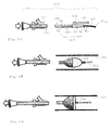
- FIGS. 2A-2C are schematic illustrations of a first exemplar embodiment of a pressure reducing infusion device (PRID) in collapsed, partially expanded, and fully expanded configurations, respectively.
- PRID pressure reducing infusion device
- FIGS. 3A-3C are schematic illustrations of a second exemplar embodiment of a pressure reducing infusion device (PRID) in collapsed, partially expanded, and fully expanded configurations, respectively.
- PRID pressure reducing infusion device
- FIG. 4A-4D are schematic illustrations of a method of the invention, including illustrating that the RGA and LGA supply the stomach from two different sides ( FIG. 4A ) advancing the PRID to a target location ( FIG. 4B ), using the PRID in a targeting mode to determine and establish an appropriate vascular pressure in which to infuse an embolizing agent ( FIG. 4C ), and using the PRID to infuse an embolizing agent into the large vessels of the fundus and in a manner that prevents flow to the body of the stomach ( FIG. 4D ).
- FIG. 5 is a graph of fundal flow targeting with the PRID relative to the expansion of the PRID.
- proximal and distal are defined in reference to the user's hand, with the term “proximal” being closer to the user's hand, and the term “distal” being further from the user's hand, unless alternate definitions are specifically provided.
- a preferred methodology has been determined for infusing the left gastric artery and its large branch vessels within the fundus with an embolizing agent while maintaining other tissues within the stomach as well as other organs having vessels in direct and indirect communication with the left gastric artery free (or at least substantially free) of the embolizing agent.
- this provides preferred results over current practices in terms of a desirable safety profile and faciliates delivery of the prescribed dose of embolizing agent to solely the intended target tissue.
- a modified Seldinger technique is utilized to introduce a delivery system for an infusion device up the aorta to the celiac axis.
- the delivery system may comprise a delivery catheter.
- the Seldinger technique which is well-known and will not be described in detail herein, access is provided from the thigh to the femoral artery and a guidewire is advanced to the aorta. The delivery catheter is advanced over the guidewire. Once the delivery catheter is at its intended position, and in accord with the method herein, a pressure reducing infusion device (PRID) is advanced through the delivery catheter and over the guidewire.
- PRID pressure reducing infusion device
- the invention is not limited to such delivery methods, and any other method or system to intravascularly advance a PRID to the target location, described below, is also contemplated to be within the scope of the invention.
- the PRID generally includes two requisite features.
- the PRID includes an infusion lumen and distal orifice through which an embolizing agent can be infused into the arterial vessel.
- the PRID includes expandable structure that can be expanded within the vessel, selectively between a non-expanded state, various partially expanded states within the vessel, and a fully expanded stated within the vessel so as to be in contact with the vessel wall.
- the expandable structure is located entirely proximal to the lumen orifice; however, it may alternatively be flush with the distal end of the expandable structure or even recessed relative to the expandable structure.
- the PRID modifies the distal pressure within the vessel relative to the non-expanded state.
- the significance of the PRID and its operation to facilitate and enhance embolic infusion specifically within the fundus is discussed below.
- the expandable structure is a microvalve device 102 that is operable between non-expandable and expandable configurations by manual control at a proximal end of the instrument.
- a microvalve device is described in detail in previously incorporated U.S. Ser. No. 14/259,293.
- a PRID instrument with microvalve device 102 more particularly includes an outer catheter 104 , an inner infusion catheter 106 extending through the outer catheter, and a dynamically adjustable microvalve 108 coupled to both of the outer and inner catheters 104 , 106 .
- the microvalve 108 includes a portion constructed with a naturally spring-biased filamentary braid construction that is biased to radially expand.
- the microvalve 108 has a proximal end 110 and a distal end 112 .
- the proximal end 110 of the microvalve is coupled to a distal end 114 of the outer catheter 104
- the distal end 112 of the microvalve is coupled to a distal end 116 of the inner catheter 106 .
- the microvalve 108 has a closed filtering distal portion 118 , preferably made from a porous polymeric material defining a pore size not exceeding 500 ⁇ m, and a proximal and distal portions 120 , the portions joined at their respective circumferences at the maximum diameter portion of the microvalve.
- the inner infusion catheter 106 is configured to deliver a therapeutic embolic agent through an orifice 122 that opens distal of the closed distal portion 118 of the microvalve.
- the microvalve 108 can be manually displaced between open and closed configurations by longitudinally displacing the distal end 116 of the inner catheter 106 relative to the distal end 114 of the outer catheter 104 by moving the proximal end of one of the catheters relative to the other.
- the microvalve 108 is moved into a collapsed configuration, suitable for delivery to the treatment site, as shown in FIG. 2A .
- the distal portion 118 is formed into a tip that is tapered to assume a form that has excellent trackability over a guidewire 130 to be advanced to the treatment site.
- the inner catheter 106 can be refracted (in the direction of arrow 132 ) a selected distance relative to the outer catheter 104 to cause the microvalve 108 to reconfigure, resulting in radial expansion toward ( FIG. 2B ) or even all the way to a vessel wall 134 ( FIG. 2C ).
- the degree of expansion is accurately controllable via relative movement at the proximal end of the instrument 102 .
- Such movement can be finely controlled with an appropriate handle, including, by way of example only, a slider or rotation knob (not shown) coupled to the respective proximal ends of the inner and outer catheters 104 , 106 .
- the partially refracted shape of the microvalve 108 presents a distal face 126 with a shape that is convex toward the upstream flow ( FIG. 2B ).
- the microvalve When the microvalve is expanded completely to the vessel wall, the microvalve preferably has a distal face 126 that is planar or concave as presented to upstream flow ( FIG. 2C ).
- the spring-bias of the microvalve 108 also operates to assist in radially expanding the microvalve, particularly when subject to a pressure differential on opposing sides of the microvalve.
- the proximal portion 120 of the microvalve preferably has a different radial expansion force than the distal portion 118 of the microvalve. More preferably, the proximal portion 120 has a substantially greater radial expansion force than the distal portion.
- the PRID may also be a balloon catheter device.
- the balloon catheter device 202 includes a catheter 204 having a first lumen for infusing the embolizing agent out of a distal orifice 222 , and a second inflation lumen (not shown).
- An elastic membrane is provided about the distal portion 216 of the catheter and has a lower surface in communication with the inflation lumen to define a fluid inflatable balloon 208 .
- FIG. 3A shows the balloon 208 in a collapsed configuration
- FIG. 3B shows the balloon 208 in a partially expanded configuration (i.e., expanded insufficiently to reach across the vessel walls 134 )
- 3C shows the balloon 208 in a fully expanded configuration (i.e., expanded fully to the vessel walls 134 ). It is preferred that the balloon 208 be proximally offset from the tip of the catheter and particularly the orifice 222 of the first lumen.
- the balloon catheter device 202 may additionally include multiple balloons, optionally of different sizes, and either radially or longitudinally offset.
- the PRID in any suitable form (device 102 referred to hereinafter by way of example only), is advanced up the aorta 12 to the celiac axis 30 , and eventually into the left gastric artery 10 ( FIG. 4A ). From the left gastric artery 10 , the PRID 102 is further advanced past the esophageal artery 22 A and then advanced to a target location 100 proximal to several of the many vessels feeding the fundus 16 ( FIG. 4B ). The PRID 12 is then infused with a contrast agent under fluoroscopy in a pressure targeting mode as follows.
- the PRID 102 is first configured in a relatively collapsed configuration.
- the relatively collapsed configuration includes a fully collapsed configuration, such as shown in FIGS.
- a contrast agent 200 adapted to fluoresce under radiographic visualization is infused through the infusion lumen of the PRID 102 and out of its distal orifice 122 while the stomach is examined under fluoroscopy.
- the vascular travel of the contrast agent 200 is observed under fluoroscopy. If the contrast agent is delivered to non-target vessels, either proximally (in reflux) or distally beyond the fundus 16 to the body 18 (both as shown in FIG.
- the microvalve 108 of the PRID 102 is reconfigured at the target location into an expanded slightly larger diameter for subsequent observation in targeting mode.
- this expanded reconfiguration results in a pressure drop in the fundus 16 and alters the path of the contrast agent 200 as well as subsequently infused embolizing agent in a subsequent step of the method.
- the contrast agent 200 is again infused through the infusion lumen of the re-sized microvalve 108 of the PRID 102 and out of the orifice and the vascular travel of the contrast agent is again observed.
- FIG. 4B illustrates that the altered pressure in the vessels created by the expanded microvalve 108 of the PRID 102 prevents refluxing of the contrast agent (even when the microvalve is not expanded to the vessel walls), but continues to allow contrast agent downstream to the larger non-target vessels of the body 18 of the stomach.
- Re-sizing of the microvalve 108 of the PRID 102 and the consequent downstream pressure drop is repeated until only the larger flow arteries of the fundus 16 are targeted, as confirmed with contrast agent visualization under fluoroscopy, and the arteries serving the body 18 of the stomach receive blood flow from the RGA instead of the LGA, which is observable when the fundal vessels are not receiving any (or any appreciable amount) of contrast agent, as seen in FIG. 4C .
- targeting mode will confirm proper configuration of the PRID upon initial infusion of the contrast agent, and that the PRID will not be required to be altered in expansion to reduce downstream pressure to target only the larger flow arteries.
- the PRID will not be required to be altered in expansion to reduce downstream pressure to target only the larger flow arteries.
- the treatment may be considered complete if sub-stasis (slow flow) is observed, or stasis (no flow) is observed (i.e., without reflux in the case of the anti-reflux system).
- the treatment may also be performed beyond stasis by either fully inflating the balloon or using an anti-reflux infusion system to infuse a greater embolic load than would be achievable with a traditional catheter (since all or most of the embolic agent would reflux in stasis conditions).
- This method provides significantly greater control over dosing than a traditional microcatheter method.
- embolic agent is infused through the infusion lumen of the sized PRID 102 (preferably together with additional contrast agent under visualization of fluoroscopy). Infusion continues, preferably until the intended dose of embolizing agent has been completely delivered.
- the infusion device and delivery system are collapsed and withdrawn, and an arterial closure device is used to close the entry wound in the femoral artery.
Abstract
Description
Claims (13)
Priority Applications (1)
| Application Number | Priority Date | Filing Date | Title |
|---|---|---|---|
| US14/259,489 US9889031B1 (en) | 2014-03-25 | 2014-04-23 | Method of gastric artery embolization |
Applications Claiming Priority (3)
| Application Number | Priority Date | Filing Date | Title |
|---|---|---|---|
| US201461970202P | 2014-03-25 | 2014-03-25 | |
| US14/259,293 US9770319B2 (en) | 2010-12-01 | 2014-04-23 | Closed tip dynamic microvalve protection device |
| US14/259,489 US9889031B1 (en) | 2014-03-25 | 2014-04-23 | Method of gastric artery embolization |
Related Parent Applications (1)
| Application Number | Title | Priority Date | Filing Date |
|---|---|---|---|
| US14/259,293 Continuation-In-Part US9770319B2 (en) | 2010-12-01 | 2014-04-23 | Closed tip dynamic microvalve protection device |
Publications (1)
| Publication Number | Publication Date |
|---|---|
| US9889031B1 true US9889031B1 (en) | 2018-02-13 |
Family
ID=61147823
Family Applications (1)
| Application Number | Title | Priority Date | Filing Date |
|---|---|---|---|
| US14/259,489 Active 2036-09-05 US9889031B1 (en) | 2014-03-25 | 2014-04-23 | Method of gastric artery embolization |
Country Status (1)
| Country | Link |
|---|---|
| US (1) | US9889031B1 (en) |
Cited By (1)
| Publication number | Priority date | Publication date | Assignee | Title |
|---|---|---|---|---|
| US20200069913A1 (en) * | 2018-09-05 | 2020-03-05 | Boston Scientific Scimed, Inc. | Aorto ostial fluid directing device |
Citations (114)
| Publication number | Priority date | Publication date | Assignee | Title |
|---|---|---|---|---|
| US4738740A (en) | 1985-11-21 | 1988-04-19 | Corvita Corporation | Method of forming implantable vascular grafts |
| US5234425A (en) | 1989-03-03 | 1993-08-10 | Thomas J. Fogarty | Variable diameter sheath method and apparatus for use in body passages |
| WO1999016382A2 (en) | 1997-09-26 | 1999-04-08 | Cardeon Corporation | Perfusion filter catheter |
| US5893869A (en) | 1997-02-19 | 1999-04-13 | University Of Iowa Research Foundation | Retrievable inferior vena cava filter system and method for use thereof |
| US5895399A (en) | 1996-07-17 | 1999-04-20 | Embol-X Inc. | Atherectomy device having trapping and excising means for removal of plaque from the aorta and other arteries |
| US5910154A (en) | 1997-05-08 | 1999-06-08 | Embol-X, Inc. | Percutaneous catheter and guidewire having filter and medical device deployment |
| WO1999044510A1 (en) | 1998-03-04 | 1999-09-10 | Bioguide Consulting, Inc. | Guidewire filter device |
| US6001118A (en) | 1997-03-06 | 1999-12-14 | Scimed Life Systems, Inc. | Distal protection device and method |
| US6059745A (en) | 1997-05-20 | 2000-05-09 | Gelbfish; Gary A. | Thrombectomy device and associated method |
| US6152946A (en) | 1998-03-05 | 2000-11-28 | Scimed Life Systems, Inc. | Distal protection device and method |
| US6168579B1 (en) | 1999-08-04 | 2001-01-02 | Scimed Life Systems, Inc. | Filter flush system and methods of use |
| US6235044B1 (en) | 1999-08-04 | 2001-05-22 | Scimed Life Systems, Inc. | Percutaneous catheter and guidewire for filtering during ablation of mycardial or vascular tissue |
| WO2001041679A1 (en) | 1999-12-08 | 2001-06-14 | Aortech Europe Limited | Hearth valve prosthesis and method of manufacture |
| WO2001045592A1 (en) | 1999-12-23 | 2001-06-28 | Percusurge, Inc. | Vascular filters with radiopaque markings |
| US6258120B1 (en) | 1997-12-23 | 2001-07-10 | Embol-X, Inc. | Implantable cerebral protection device and methods of use |
| WO2001049215A2 (en) | 1999-12-30 | 2001-07-12 | Advanced Cardiovascular Systems, Inc. | Embolic protection devices |
| US6306163B1 (en) | 1998-08-04 | 2001-10-23 | Advanced Cardiovascular Systems, Inc. | Assembly for collecting emboli and method of use |
| US6306074B1 (en) | 1994-10-27 | 2001-10-23 | Novoste Corporation | Method and apparatus for radiation treatment of a desired area in the vascular system of a patient |
| US6371971B1 (en) | 1999-11-15 | 2002-04-16 | Scimed Life Systems, Inc. | Guidewire filter and methods of use |
| US6383206B1 (en) | 1999-12-30 | 2002-05-07 | Advanced Cardiovascular Systems, Inc. | Embolic protection system and method including filtering elements |
| US6395014B1 (en) | 1997-09-26 | 2002-05-28 | John A. Macoviak | Cerebral embolic protection assembly and associated methods |
| EP1226795A2 (en) | 2001-01-25 | 2002-07-31 | Jennifer L. Pavlovic | Filter device |
| US6436112B2 (en) | 1996-02-02 | 2002-08-20 | The Regents Of The University Of California | Method of using a clot capture coil |
| US6443926B1 (en) | 2000-02-01 | 2002-09-03 | Harold D. Kletschka | Embolic protection device having expandable trap |
| US20020161390A1 (en) | 2001-04-30 | 2002-10-31 | Mouw Steven L. | Balloon actuated apparatus having multiple embolic filters, and method of use |
| US6485502B2 (en) | 2000-03-10 | 2002-11-26 | T. Anthony Don Michael | Vascular embolism prevention device employing filters |
| US6533800B1 (en) | 2001-07-25 | 2003-03-18 | Coaxia, Inc. | Devices and methods for preventing distal embolization using flow reversal in arteries having collateral blood flow |
| US6537294B1 (en) | 2000-10-17 | 2003-03-25 | Advanced Cardiovascular Systems, Inc. | Delivery systems for embolic filter devices |
| US6540722B1 (en) | 1999-12-30 | 2003-04-01 | Advanced Cardiovascular Systems, Inc. | Embolic protection devices |
| US6551303B1 (en) | 1999-10-27 | 2003-04-22 | Atritech, Inc. | Barrier device for ostium of left atrial appendage |
| US20030097114A1 (en) | 2001-11-20 | 2003-05-22 | The Cleveland Clinic Foundation | Apparatus and method for performing thrombolysis |
| US6582396B1 (en) | 1998-05-13 | 2003-06-24 | Arteria Medical Science, Inc. | Puncture resistant balloon for use in carotid artery procedures and methods of use |
| US6589264B1 (en) | 1996-05-14 | 2003-07-08 | Edwards Lifesciences Corp. | Aortic occluder with associated filter and methods of use during cardiac surgery |
| US20030187474A1 (en) | 1997-11-07 | 2003-10-02 | Martin Keegan | Embolic protection system |
| US6635070B2 (en) | 2001-05-21 | 2003-10-21 | Bacchus Vascular, Inc. | Apparatus and methods for capturing particulate material within blood vessels |
| US6645220B1 (en) | 1999-12-30 | 2003-11-11 | Advanced Cardiovascular Systems, Inc. | Embolic protection system and method including and embolic-capturing filter |
| US6645222B1 (en) | 1998-05-13 | 2003-11-11 | Arteria Medical Science, Inc. | Puncture resistant branch artery occlusion device and methods of use |
| US6645223B2 (en) | 2001-04-30 | 2003-11-11 | Advanced Cardiovascular Systems, Inc. | Deployment and recovery control systems for embolic protection devices |
| US6652556B1 (en) | 1999-10-27 | 2003-11-25 | Atritech, Inc. | Filter apparatus for ostium of left atrial appendage |
| US6652555B1 (en) | 1999-10-27 | 2003-11-25 | Atritech, Inc. | Barrier device for covering the ostium of left atrial appendage |
| US6656351B2 (en) | 2001-08-31 | 2003-12-02 | Advanced Cardiovascular Systems, Inc. | Embolic protection devices one way porous membrane |
| US6676682B1 (en) | 1997-05-08 | 2004-01-13 | Scimed Life Systems, Inc. | Percutaneous catheter and guidewire having filter and medical device deployment capabilities |
| US6692513B2 (en) | 2000-06-30 | 2004-02-17 | Viacor, Inc. | Intravascular filter with debris entrapment mechanism |
| US6695858B1 (en) | 1998-02-10 | 2004-02-24 | Artemis Medical, Inc. | Medical device and methods for use |
| US6702834B1 (en) | 1999-12-30 | 2004-03-09 | Advanced Cardiovascular Systems, Inc. | Embolic protection devices |
| US6706053B1 (en) | 2000-04-28 | 2004-03-16 | Advanced Cardiovascular Systems, Inc. | Nitinol alloy design for sheath deployable and re-sheathable vascular devices |
| US6706055B2 (en) | 2001-04-03 | 2004-03-16 | Medtronic Ave Inc. | Guidewire apparatus for temporary distal embolic protection |
| US20040068288A1 (en) | 1999-12-23 | 2004-04-08 | Olin Palmer | Intravascular device and system |
| WO2004043293A2 (en) | 2002-11-13 | 2004-05-27 | Viacor, Inc. | Cardiac valve procedure methods and devices |
| US20040220609A1 (en) | 2001-04-03 | 2004-11-04 | Medtronic Vascular, Inc. | Temporary intraluminal filter guidewire |
| US20040225354A1 (en) | 2003-04-30 | 2004-11-11 | Medtronic Vascular, Inc. | Percutaneously delivered temporary valve Assembly |
| US6830579B2 (en) | 2001-05-01 | 2004-12-14 | Coaxia, Inc. | Devices and methods for preventing distal embolization using flow reversal and perfusion augmentation within the cerebral vasculature |
| US20040260333A1 (en) | 1997-11-12 | 2004-12-23 | Dubrul William R. | Medical device and method |
| US6837898B2 (en) | 2001-11-30 | 2005-01-04 | Advanced Cardiovascular Systems, Inc. | Intraluminal delivery system for an attachable treatment device |
| US20050010285A1 (en) | 1999-01-27 | 2005-01-13 | Lambrecht Gregory H. | Cardiac valve procedure methods and devices |
| US20050015048A1 (en) | 2003-03-12 | 2005-01-20 | Chiu Jessica G. | Infusion treatment agents, catheters, filter devices, and occlusion devices, and use thereof |
| US20050015112A1 (en) | 2000-01-27 | 2005-01-20 | Cohn William E. | Cardiac valve procedure methods and devices |
| US6855154B2 (en) | 2000-08-11 | 2005-02-15 | University Of Louisville Research Foundation, Inc. | Endovascular aneurysm treatment device and method |
| US6866677B2 (en) | 2001-04-03 | 2005-03-15 | Medtronic Ave, Inc. | Temporary intraluminal filter guidewire and methods of use |
| US6887258B2 (en) | 2002-06-26 | 2005-05-03 | Advanced Cardiovascular Systems, Inc. | Embolic filtering devices for bifurcated vessels |
| US20050119688A1 (en) | 2003-10-06 | 2005-06-02 | Bjarne Bergheim | Method and assembly for distal embolic protection |
| US6902540B2 (en) | 2001-08-22 | 2005-06-07 | Gerald Dorros | Apparatus and methods for treating stroke and controlling cerebral flow characteristics |
| US6908474B2 (en) | 1998-05-13 | 2005-06-21 | Gore Enterprise Holdings, Inc. | Apparatus and methods for reducing embolization during treatment of carotid artery disease |
| US6911036B2 (en) | 2001-04-03 | 2005-06-28 | Medtronic Vascular, Inc. | Guidewire apparatus for temporary distal embolic protection |
| US6936060B2 (en) | 1998-05-13 | 2005-08-30 | Arteria Medical Sciences, Inc. | Apparatus and methods for removing emboli during a surgical procedure |
| US6939362B2 (en) | 2001-11-27 | 2005-09-06 | Advanced Cardiovascular Systems, Inc. | Offset proximal cage for embolic filtering devices |
| US6964670B1 (en) | 2000-07-13 | 2005-11-15 | Advanced Cardiovascular Systems, Inc. | Embolic protection guide wire |
| US6974469B2 (en) | 1997-03-06 | 2005-12-13 | Scimed Life Systems, Inc. | Distal protection device and method |
| US7044958B2 (en) | 2001-04-03 | 2006-05-16 | Medtronic Vascular, Inc. | Temporary device for capturing embolic material |
| US7044966B2 (en) | 2003-10-06 | 2006-05-16 | 3F Therapeutics, Inc. | Minimally invasive valve replacement system |
| US20060167537A1 (en) | 2002-04-08 | 2006-07-27 | Rolf Larsson | Stent assembly and device for application thereof |
| US20060173490A1 (en) | 2005-02-01 | 2006-08-03 | Boston Scientific Scimed, Inc. | Filter system and method |
| US7162303B2 (en) | 2002-04-08 | 2007-01-09 | Ardian, Inc. | Renal nerve stimulation method and apparatus for treatment of patients |
| US7169164B2 (en) | 2000-09-21 | 2007-01-30 | Atritech, Inc. | Apparatus for implanting devices in atrial appendages |
| US7172621B2 (en) | 2004-09-24 | 2007-02-06 | Laurence Theron | Method of performing protected angioplasty and stenting at a carotid bifurcation |
| US7172614B2 (en) | 2002-06-27 | 2007-02-06 | Advanced Cardiovascular Systems, Inc. | Support structures for embolic filtering devices |
| US7214237B2 (en) | 2001-03-12 | 2007-05-08 | Don Michael T Anthony | Vascular filter with improved strength and flexibility |
| US20070106324A1 (en) | 2001-03-01 | 2007-05-10 | Scimed Life Systems, Inc. | Intravascular filter retrieval device having an actuatable dilator tip |
| US7223253B2 (en) | 2002-07-29 | 2007-05-29 | Gore Enterprise Holdings, Inc. | Blood aspiration system and methods of use |
| US7232453B2 (en) | 2001-12-05 | 2007-06-19 | Sagax, Inc. | Endovascular device for entrapment of particulate matter and method for use |
| US7232452B2 (en) | 2002-07-12 | 2007-06-19 | Ev3 Inc. | Device to create proximal stasis |
| EP1803423A2 (en) | 2005-12-30 | 2007-07-04 | Cordis Corporation | Stent delivery system with improved delivery force distribution |
| US7241304B2 (en) | 2001-12-21 | 2007-07-10 | Advanced Cardiovascular Systems, Inc. | Flexible and conformable embolic filtering devices |
| US7250041B2 (en) | 2003-03-12 | 2007-07-31 | Abbott Cardiovascular Systems Inc. | Retrograde pressure regulated infusion |
| US20070179590A1 (en) | 2005-12-29 | 2007-08-02 | Wenfeng Lu | Hybrid intraluminal device with varying expansion force |
| US7252675B2 (en) | 2002-09-30 | 2007-08-07 | Advanced Cardiovascular, Inc. | Embolic filtering devices |
| US7279000B2 (en) | 2004-09-29 | 2007-10-09 | Angiodynamics Inc | Permanent blood clot filter with capability of being retrieved |
| US7322957B2 (en) | 2000-02-01 | 2008-01-29 | Harold D. Kletschka | Angioplasty device and method of making same |
| US20080033341A1 (en) | 2006-08-04 | 2008-02-07 | Bay Holdings Ltd. | Methods and devices for reducing or blocking blood flow to a selected blood vessel or part thereof |
| US20080039786A1 (en) | 2006-08-10 | 2008-02-14 | Boston Scientific Scimed, Inc. | Medical device for vessel compatibility during high pressure infusion |
| US7331973B2 (en) | 2002-09-30 | 2008-02-19 | Avdanced Cardiovascular Systems, Inc. | Guide wire with embolic filtering attachment |
| US7338510B2 (en) | 2001-06-29 | 2008-03-04 | Advanced Cardiovascular Systems, Inc. | Variable thickness embolic filtering devices and method of manufacturing the same |
| US7344549B2 (en) | 2002-01-31 | 2008-03-18 | Advanced Cardiovascular Systems, Inc. | Expandable cages for embolic filtering devices |
| US20090076409A1 (en) | 2006-06-28 | 2009-03-19 | Ardian, Inc. | Methods and systems for thermally-induced renal neuromodulation |
| US7537600B2 (en) | 2003-06-12 | 2009-05-26 | Boston Scientific Scimed, Inc. | Valved embolic protection filter |
| US7544202B2 (en) | 2004-06-25 | 2009-06-09 | Angiodynamics, Inc. | Retrievable blood clot filter |
| US7582100B2 (en) | 2005-01-03 | 2009-09-01 | Crux Biomedical, Inc. | Spiral shaped filter |
| US20090222035A1 (en) | 2006-03-27 | 2009-09-03 | Tel Hashomer Medical Research Infrastructure And S | Intraluminal Mass Collector |
| US7585309B2 (en) | 2002-05-16 | 2009-09-08 | Boston Scientific Scimed, Inc. | Aortic filter |
| US7591832B2 (en) | 2003-04-24 | 2009-09-22 | Medtronic, Inc. | Expandable guide sheath and apparatus with distal protection and methods for use |
| US7653438B2 (en) | 2002-04-08 | 2010-01-26 | Ardian, Inc. | Methods and apparatus for renal neuromodulation |
| US7833242B2 (en) | 1997-11-07 | 2010-11-16 | Salviac Limited | Embolic protection device |
| US7842084B2 (en) | 2005-06-21 | 2010-11-30 | 3F Therapeutics, Inc. | Method and systems for sizing, folding, holding, and delivering a heart valve prosthesis |
| US7853333B2 (en) | 2002-04-08 | 2010-12-14 | Ardian, Inc. | Methods and apparatus for multi-vessel renal neuromodulation |
| US7873417B2 (en) | 2002-04-08 | 2011-01-18 | Ardian, Inc. | Methods and apparatus for pulsed electric field neuromodulation via an intra-to-extravascular approach |
| US7937143B2 (en) | 2004-11-02 | 2011-05-03 | Ardian, Inc. | Methods and apparatus for inducing controlled renal neuromodulation |
| US20110137399A1 (en) | 2009-12-02 | 2011-06-09 | Chomas James E | Microvalve Protection Device and Method of Use for Protection Against Embolization Agent Reflux |
| US20110288529A1 (en) | 2010-05-19 | 2011-11-24 | Fulton Richard E | Augmented delivery catheter and method |
| US20120116351A1 (en) | 2009-12-02 | 2012-05-10 | Chomas James E | Method of Operating a Microvalve Protection Device |
| US8257384B2 (en) * | 2005-12-21 | 2012-09-04 | Nexeon Medsystems, Inc. | Interventional catheter for retrograde use having embolic protection capability and methods of use |
| US20120259206A1 (en) | 2011-04-08 | 2012-10-11 | Salient Surgical Technologies, Inc. | Catheter Systems and Methods of Use |
| US20130079731A1 (en) | 2011-09-28 | 2013-03-28 | James E. Chomas | Flow Directional Infusion Device |
| US8500775B2 (en) | 2009-12-02 | 2013-08-06 | Surefire Medical, Inc. | Protection device and method against embolization agent reflux |
| US20130226166A1 (en) | 2012-02-28 | 2013-08-29 | James E. Chomas | Renal Nerve Neuromodulation Device |
-
2014
- 2014-04-23 US US14/259,489 patent/US9889031B1/en active Active
Patent Citations (158)
| Publication number | Priority date | Publication date | Assignee | Title |
|---|---|---|---|---|
| US4738740A (en) | 1985-11-21 | 1988-04-19 | Corvita Corporation | Method of forming implantable vascular grafts |
| US5234425A (en) | 1989-03-03 | 1993-08-10 | Thomas J. Fogarty | Variable diameter sheath method and apparatus for use in body passages |
| US6306074B1 (en) | 1994-10-27 | 2001-10-23 | Novoste Corporation | Method and apparatus for radiation treatment of a desired area in the vascular system of a patient |
| US6692509B2 (en) | 1996-02-02 | 2004-02-17 | Regents Of The University Of California | Method of using a clot capture coil |
| US6530935B2 (en) | 1996-02-02 | 2003-03-11 | Regents Of The University Of California, The | Clot capture coil and method of using the same |
| US6692508B2 (en) | 1996-02-02 | 2004-02-17 | The Regents Of The University Of California | Method of using a clot capture coil |
| US6436112B2 (en) | 1996-02-02 | 2002-08-20 | The Regents Of The University Of California | Method of using a clot capture coil |
| US6589264B1 (en) | 1996-05-14 | 2003-07-08 | Edwards Lifesciences Corp. | Aortic occluder with associated filter and methods of use during cardiac surgery |
| US7306575B2 (en) | 1996-05-14 | 2007-12-11 | Edwards Lifesciences Corporation | Aortic occluder with associated filter and methods of use during cardiac surgery |
| US6592546B1 (en) | 1996-05-14 | 2003-07-15 | Edwards Lifesciences Corp. | Aortic occluder with associated filter and methods of use during cardiac surgery |
| US5895399A (en) | 1996-07-17 | 1999-04-20 | Embol-X Inc. | Atherectomy device having trapping and excising means for removal of plaque from the aorta and other arteries |
| US6010522A (en) | 1996-07-17 | 2000-01-04 | Embol-X, Inc. | Atherectomy device having trapping and excising means for removal of plaque from the aorta and other arteries |
| US6309399B1 (en) | 1996-07-17 | 2001-10-30 | Scimed Life Systems, Inc. | Atherectomy device having trapping and excising means for removal of plaque from the aorta and other arteries |
| US6179851B1 (en) | 1996-07-17 | 2001-01-30 | Scimed Life Systems, Inc. | Guiding catheter for positioning a medical device within an artery |
| US5893869A (en) | 1997-02-19 | 1999-04-13 | University Of Iowa Research Foundation | Retrievable inferior vena cava filter system and method for use thereof |
| US6001118A (en) | 1997-03-06 | 1999-12-14 | Scimed Life Systems, Inc. | Distal protection device and method |
| US6974469B2 (en) | 1997-03-06 | 2005-12-13 | Scimed Life Systems, Inc. | Distal protection device and method |
| US6042598A (en) | 1997-05-08 | 2000-03-28 | Embol-X Inc. | Method of protecting a patient from embolization during cardiac surgery |
| US6537297B2 (en) | 1997-05-08 | 2003-03-25 | Embol-X, Inc. | Methods of protecting a patient from embolization during surgery |
| US6964673B2 (en) | 1997-05-08 | 2005-11-15 | Scimed Life Systems, Inc. | Percutaneous catheter and guidewire having filter and medical device deployment capabilities |
| US6676682B1 (en) | 1997-05-08 | 2004-01-13 | Scimed Life Systems, Inc. | Percutaneous catheter and guidewire having filter and medical device deployment capabilities |
| US5910154A (en) | 1997-05-08 | 1999-06-08 | Embol-X, Inc. | Percutaneous catheter and guidewire having filter and medical device deployment |
| US6371969B1 (en) | 1997-05-08 | 2002-04-16 | Scimed Life Systems, Inc. | Distal protection device and method |
| US6165200A (en) | 1997-05-08 | 2000-12-26 | Scimed Life Systems, Inc. | Percutaneous catheter and guidewire having filter and medical device deployment capabilities |
| US6027520A (en) | 1997-05-08 | 2000-02-22 | Embol-X, Inc. | Percutaneous catheter and guidewire having filter and medical device deployment capabilities |
| US5911734A (en) | 1997-05-08 | 1999-06-15 | Embol-X, Inc. | Percutaneous catheter and guidewire having filter and medical device deployment capabilities |
| US6059745A (en) | 1997-05-20 | 2000-05-09 | Gelbfish; Gary A. | Thrombectomy device and associated method |
| US6361545B1 (en) | 1997-09-26 | 2002-03-26 | Cardeon Corporation | Perfusion filter catheter |
| US6395014B1 (en) | 1997-09-26 | 2002-05-28 | John A. Macoviak | Cerebral embolic protection assembly and associated methods |
| WO1999016382A2 (en) | 1997-09-26 | 1999-04-08 | Cardeon Corporation | Perfusion filter catheter |
| US20020161394A1 (en) | 1997-09-26 | 2002-10-31 | Macoviak John A. | Aortic filter catheter |
| US20030187474A1 (en) | 1997-11-07 | 2003-10-02 | Martin Keegan | Embolic protection system |
| US7833242B2 (en) | 1997-11-07 | 2010-11-16 | Salviac Limited | Embolic protection device |
| US20040260333A1 (en) | 1997-11-12 | 2004-12-23 | Dubrul William R. | Medical device and method |
| US6499487B1 (en) | 1997-12-23 | 2002-12-31 | Embol-X, Inc. | Implantable cerebral protection device and methods of use |
| US6258120B1 (en) | 1997-12-23 | 2001-07-10 | Embol-X, Inc. | Implantable cerebral protection device and methods of use |
| US6695858B1 (en) | 1998-02-10 | 2004-02-24 | Artemis Medical, Inc. | Medical device and methods for use |
| WO1999044510A1 (en) | 1998-03-04 | 1999-09-10 | Bioguide Consulting, Inc. | Guidewire filter device |
| US6152946A (en) | 1998-03-05 | 2000-11-28 | Scimed Life Systems, Inc. | Distal protection device and method |
| US6582396B1 (en) | 1998-05-13 | 2003-06-24 | Arteria Medical Science, Inc. | Puncture resistant balloon for use in carotid artery procedures and methods of use |
| US6908474B2 (en) | 1998-05-13 | 2005-06-21 | Gore Enterprise Holdings, Inc. | Apparatus and methods for reducing embolization during treatment of carotid artery disease |
| US6645222B1 (en) | 1998-05-13 | 2003-11-11 | Arteria Medical Science, Inc. | Puncture resistant branch artery occlusion device and methods of use |
| US6936060B2 (en) | 1998-05-13 | 2005-08-30 | Arteria Medical Sciences, Inc. | Apparatus and methods for removing emboli during a surgical procedure |
| US6306163B1 (en) | 1998-08-04 | 2001-10-23 | Advanced Cardiovascular Systems, Inc. | Assembly for collecting emboli and method of use |
| US20050010285A1 (en) | 1999-01-27 | 2005-01-13 | Lambrecht Gregory H. | Cardiac valve procedure methods and devices |
| US20050261759A1 (en) | 1999-01-27 | 2005-11-24 | Medtronic, Inc. | Cardiac valve procedure methods and devices |
| US6673090B2 (en) | 1999-08-04 | 2004-01-06 | Scimed Life Systems, Inc. | Percutaneous catheter and guidewire for filtering during ablation of myocardial or vascular tissue |
| US6620148B1 (en) | 1999-08-04 | 2003-09-16 | Scimed Life Systems, Inc. | Filter flush system and methods of use |
| US6168579B1 (en) | 1999-08-04 | 2001-01-02 | Scimed Life Systems, Inc. | Filter flush system and methods of use |
| US7326226B2 (en) | 1999-08-04 | 2008-02-05 | Boston Scientific Scimed, Inc. | Percutaneous catheter and guidewire for filtering during ablation of myocardial or vascular tissue |
| US6235044B1 (en) | 1999-08-04 | 2001-05-22 | Scimed Life Systems, Inc. | Percutaneous catheter and guidewire for filtering during ablation of mycardial or vascular tissue |
| US6551303B1 (en) | 1999-10-27 | 2003-04-22 | Atritech, Inc. | Barrier device for ostium of left atrial appendage |
| US6730108B2 (en) | 1999-10-27 | 2004-05-04 | Atritech, Inc. | Barrier device for ostium of left atrial appendage |
| US6689150B1 (en) | 1999-10-27 | 2004-02-10 | Atritech, Inc. | Filter apparatus for ostium of left atrial appendage |
| US6652556B1 (en) | 1999-10-27 | 2003-11-25 | Atritech, Inc. | Filter apparatus for ostium of left atrial appendage |
| US6652555B1 (en) | 1999-10-27 | 2003-11-25 | Atritech, Inc. | Barrier device for covering the ostium of left atrial appendage |
| US6371971B1 (en) | 1999-11-15 | 2002-04-16 | Scimed Life Systems, Inc. | Guidewire filter and methods of use |
| WO2001041679A1 (en) | 1999-12-08 | 2001-06-14 | Aortech Europe Limited | Hearth valve prosthesis and method of manufacture |
| US20040068288A1 (en) | 1999-12-23 | 2004-04-08 | Olin Palmer | Intravascular device and system |
| WO2001045592A1 (en) | 1999-12-23 | 2001-06-28 | Percusurge, Inc. | Vascular filters with radiopaque markings |
| US6540722B1 (en) | 1999-12-30 | 2003-04-01 | Advanced Cardiovascular Systems, Inc. | Embolic protection devices |
| WO2001049215A2 (en) | 1999-12-30 | 2001-07-12 | Advanced Cardiovascular Systems, Inc. | Embolic protection devices |
| US6383206B1 (en) | 1999-12-30 | 2002-05-07 | Advanced Cardiovascular Systems, Inc. | Embolic protection system and method including filtering elements |
| US7217255B2 (en) | 1999-12-30 | 2007-05-15 | Advanced Cardiovascular Systems, Inc. | Embolic protection devices |
| US6695813B1 (en) | 1999-12-30 | 2004-02-24 | Advanced Cardiovascular Systems, Inc. | Embolic protection devices |
| US6702834B1 (en) | 1999-12-30 | 2004-03-09 | Advanced Cardiovascular Systems, Inc. | Embolic protection devices |
| US6645220B1 (en) | 1999-12-30 | 2003-11-11 | Advanced Cardiovascular Systems, Inc. | Embolic protection system and method including and embolic-capturing filter |
| US20050015112A1 (en) | 2000-01-27 | 2005-01-20 | Cohn William E. | Cardiac valve procedure methods and devices |
| US6896690B1 (en) | 2000-01-27 | 2005-05-24 | Viacor, Inc. | Cardiac valve procedure methods and devices |
| US6443926B1 (en) | 2000-02-01 | 2002-09-03 | Harold D. Kletschka | Embolic protection device having expandable trap |
| US7922691B2 (en) * | 2000-02-01 | 2011-04-12 | Kletschka Foundation | Angioplasty device and method of making same |
| US6485456B1 (en) | 2000-02-01 | 2002-11-26 | Harold D. Kletschka | Embolic protection device having expandable trap |
| US7322957B2 (en) | 2000-02-01 | 2008-01-29 | Harold D. Kletschka | Angioplasty device and method of making same |
| US6607506B2 (en) | 2000-02-01 | 2003-08-19 | Harold D. Kletschka | Embolic protection device having an expandable trap |
| US6485502B2 (en) | 2000-03-10 | 2002-11-26 | T. Anthony Don Michael | Vascular embolism prevention device employing filters |
| US6706053B1 (en) | 2000-04-28 | 2004-03-16 | Advanced Cardiovascular Systems, Inc. | Nitinol alloy design for sheath deployable and re-sheathable vascular devices |
| US6692513B2 (en) | 2000-06-30 | 2004-02-17 | Viacor, Inc. | Intravascular filter with debris entrapment mechanism |
| US6964670B1 (en) | 2000-07-13 | 2005-11-15 | Advanced Cardiovascular Systems, Inc. | Embolic protection guide wire |
| US6855154B2 (en) | 2000-08-11 | 2005-02-15 | University Of Louisville Research Foundation, Inc. | Endovascular aneurysm treatment device and method |
| US7169164B2 (en) | 2000-09-21 | 2007-01-30 | Atritech, Inc. | Apparatus for implanting devices in atrial appendages |
| US6537294B1 (en) | 2000-10-17 | 2003-03-25 | Advanced Cardiovascular Systems, Inc. | Delivery systems for embolic filter devices |
| US7425215B2 (en) | 2000-10-17 | 2008-09-16 | Advanced Cardiovascular Systems, Inc. | Delivery systems for embolic filter devices |
| EP1226795A2 (en) | 2001-01-25 | 2002-07-31 | Jennifer L. Pavlovic | Filter device |
| US20070106324A1 (en) | 2001-03-01 | 2007-05-10 | Scimed Life Systems, Inc. | Intravascular filter retrieval device having an actuatable dilator tip |
| US7214237B2 (en) | 2001-03-12 | 2007-05-08 | Don Michael T Anthony | Vascular filter with improved strength and flexibility |
| US6866677B2 (en) | 2001-04-03 | 2005-03-15 | Medtronic Ave, Inc. | Temporary intraluminal filter guidewire and methods of use |
| US6818006B2 (en) | 2001-04-03 | 2004-11-16 | Medtronic Vascular, Inc. | Temporary intraluminal filter guidewire |
| US7371249B2 (en) | 2001-04-03 | 2008-05-13 | Medtronic Vascular, Inc. | Temporary intraluminal filter guidewire and methods of use |
| US6706055B2 (en) | 2001-04-03 | 2004-03-16 | Medtronic Ave Inc. | Guidewire apparatus for temporary distal embolic protection |
| US6911036B2 (en) | 2001-04-03 | 2005-06-28 | Medtronic Vascular, Inc. | Guidewire apparatus for temporary distal embolic protection |
| US7066946B2 (en) | 2001-04-03 | 2006-06-27 | Medtronic Vascular, Inc | Temporary intraluminal filter guidewire |
| US7044958B2 (en) | 2001-04-03 | 2006-05-16 | Medtronic Vascular, Inc. | Temporary device for capturing embolic material |
| US20040220609A1 (en) | 2001-04-03 | 2004-11-04 | Medtronic Vascular, Inc. | Temporary intraluminal filter guidewire |
| US6746469B2 (en) | 2001-04-30 | 2004-06-08 | Advanced Cardiovascular Systems, Inc. | Balloon actuated apparatus having multiple embolic filters, and method of use |
| US6645223B2 (en) | 2001-04-30 | 2003-11-11 | Advanced Cardiovascular Systems, Inc. | Deployment and recovery control systems for embolic protection devices |
| US20020161390A1 (en) | 2001-04-30 | 2002-10-31 | Mouw Steven L. | Balloon actuated apparatus having multiple embolic filters, and method of use |
| US6830579B2 (en) | 2001-05-01 | 2004-12-14 | Coaxia, Inc. | Devices and methods for preventing distal embolization using flow reversal and perfusion augmentation within the cerebral vasculature |
| US6635070B2 (en) | 2001-05-21 | 2003-10-21 | Bacchus Vascular, Inc. | Apparatus and methods for capturing particulate material within blood vessels |
| US7338510B2 (en) | 2001-06-29 | 2008-03-04 | Advanced Cardiovascular Systems, Inc. | Variable thickness embolic filtering devices and method of manufacturing the same |
| US6533800B1 (en) | 2001-07-25 | 2003-03-18 | Coaxia, Inc. | Devices and methods for preventing distal embolization using flow reversal in arteries having collateral blood flow |
| US6902540B2 (en) | 2001-08-22 | 2005-06-07 | Gerald Dorros | Apparatus and methods for treating stroke and controlling cerebral flow characteristics |
| US6656351B2 (en) | 2001-08-31 | 2003-12-02 | Advanced Cardiovascular Systems, Inc. | Embolic protection devices one way porous membrane |
| US20030097114A1 (en) | 2001-11-20 | 2003-05-22 | The Cleveland Clinic Foundation | Apparatus and method for performing thrombolysis |
| US6939362B2 (en) | 2001-11-27 | 2005-09-06 | Advanced Cardiovascular Systems, Inc. | Offset proximal cage for embolic filtering devices |
| US6837898B2 (en) | 2001-11-30 | 2005-01-04 | Advanced Cardiovascular Systems, Inc. | Intraluminal delivery system for an attachable treatment device |
| US7232453B2 (en) | 2001-12-05 | 2007-06-19 | Sagax, Inc. | Endovascular device for entrapment of particulate matter and method for use |
| US7241304B2 (en) | 2001-12-21 | 2007-07-10 | Advanced Cardiovascular Systems, Inc. | Flexible and conformable embolic filtering devices |
| US7344549B2 (en) | 2002-01-31 | 2008-03-18 | Advanced Cardiovascular Systems, Inc. | Expandable cages for embolic filtering devices |
| US7647115B2 (en) | 2002-04-08 | 2010-01-12 | Ardian, Inc. | Renal nerve stimulation method and apparatus for treatment of patients |
| US7853333B2 (en) | 2002-04-08 | 2010-12-14 | Ardian, Inc. | Methods and apparatus for multi-vessel renal neuromodulation |
| US7873417B2 (en) | 2002-04-08 | 2011-01-18 | Ardian, Inc. | Methods and apparatus for pulsed electric field neuromodulation via an intra-to-extravascular approach |
| US7653438B2 (en) | 2002-04-08 | 2010-01-26 | Ardian, Inc. | Methods and apparatus for renal neuromodulation |
| US20060167537A1 (en) | 2002-04-08 | 2006-07-27 | Rolf Larsson | Stent assembly and device for application thereof |
| US7162303B2 (en) | 2002-04-08 | 2007-01-09 | Ardian, Inc. | Renal nerve stimulation method and apparatus for treatment of patients |
| US7585309B2 (en) | 2002-05-16 | 2009-09-08 | Boston Scientific Scimed, Inc. | Aortic filter |
| US7572272B2 (en) | 2002-06-26 | 2009-08-11 | Advanced Cardiovascular Systems, Inc. | Embolic filtering devices for bifurcated vessels |
| US6887258B2 (en) | 2002-06-26 | 2005-05-03 | Advanced Cardiovascular Systems, Inc. | Embolic filtering devices for bifurcated vessels |
| US7172614B2 (en) | 2002-06-27 | 2007-02-06 | Advanced Cardiovascular Systems, Inc. | Support structures for embolic filtering devices |
| US7232452B2 (en) | 2002-07-12 | 2007-06-19 | Ev3 Inc. | Device to create proximal stasis |
| US7223253B2 (en) | 2002-07-29 | 2007-05-29 | Gore Enterprise Holdings, Inc. | Blood aspiration system and methods of use |
| US7252675B2 (en) | 2002-09-30 | 2007-08-07 | Advanced Cardiovascular, Inc. | Embolic filtering devices |
| US7331973B2 (en) | 2002-09-30 | 2008-02-19 | Avdanced Cardiovascular Systems, Inc. | Guide wire with embolic filtering attachment |
| WO2004043293A2 (en) | 2002-11-13 | 2004-05-27 | Viacor, Inc. | Cardiac valve procedure methods and devices |
| US20090018498A1 (en) | 2003-03-12 | 2009-01-15 | Abbott Cardiovascular Systems Inc. | Infusion treatment agents, catheters, filter devices, and occlusion devices, and use thereof |
| US20050015048A1 (en) | 2003-03-12 | 2005-01-20 | Chiu Jessica G. | Infusion treatment agents, catheters, filter devices, and occlusion devices, and use thereof |
| US7250041B2 (en) | 2003-03-12 | 2007-07-31 | Abbott Cardiovascular Systems Inc. | Retrograde pressure regulated infusion |
| US7591832B2 (en) | 2003-04-24 | 2009-09-22 | Medtronic, Inc. | Expandable guide sheath and apparatus with distal protection and methods for use |
| US20040225354A1 (en) | 2003-04-30 | 2004-11-11 | Medtronic Vascular, Inc. | Percutaneously delivered temporary valve Assembly |
| US6989027B2 (en) | 2003-04-30 | 2006-01-24 | Medtronic Vascular Inc. | Percutaneously delivered temporary valve assembly |
| US7537600B2 (en) | 2003-06-12 | 2009-05-26 | Boston Scientific Scimed, Inc. | Valved embolic protection filter |
| US7101396B2 (en) | 2003-10-06 | 2006-09-05 | 3F Therapeutics, Inc. | Minimally invasive valve replacement system |
| US20050119688A1 (en) | 2003-10-06 | 2005-06-02 | Bjarne Bergheim | Method and assembly for distal embolic protection |
| US7044966B2 (en) | 2003-10-06 | 2006-05-16 | 3F Therapeutics, Inc. | Minimally invasive valve replacement system |
| US7604650B2 (en) | 2003-10-06 | 2009-10-20 | 3F Therapeutics, Inc. | Method and assembly for distal embolic protection |
| US7544202B2 (en) | 2004-06-25 | 2009-06-09 | Angiodynamics, Inc. | Retrievable blood clot filter |
| US7172621B2 (en) | 2004-09-24 | 2007-02-06 | Laurence Theron | Method of performing protected angioplasty and stenting at a carotid bifurcation |
| US7279000B2 (en) | 2004-09-29 | 2007-10-09 | Angiodynamics Inc | Permanent blood clot filter with capability of being retrieved |
| US7937143B2 (en) | 2004-11-02 | 2011-05-03 | Ardian, Inc. | Methods and apparatus for inducing controlled renal neuromodulation |
| US7582100B2 (en) | 2005-01-03 | 2009-09-01 | Crux Biomedical, Inc. | Spiral shaped filter |
| US20060173490A1 (en) | 2005-02-01 | 2006-08-03 | Boston Scientific Scimed, Inc. | Filter system and method |
| US7842084B2 (en) | 2005-06-21 | 2010-11-30 | 3F Therapeutics, Inc. | Method and systems for sizing, folding, holding, and delivering a heart valve prosthesis |
| US8257384B2 (en) * | 2005-12-21 | 2012-09-04 | Nexeon Medsystems, Inc. | Interventional catheter for retrograde use having embolic protection capability and methods of use |
| US20070179590A1 (en) | 2005-12-29 | 2007-08-02 | Wenfeng Lu | Hybrid intraluminal device with varying expansion force |
| EP1803423A2 (en) | 2005-12-30 | 2007-07-04 | Cordis Corporation | Stent delivery system with improved delivery force distribution |
| US20090222035A1 (en) | 2006-03-27 | 2009-09-03 | Tel Hashomer Medical Research Infrastructure And S | Intraluminal Mass Collector |
| US20090076409A1 (en) | 2006-06-28 | 2009-03-19 | Ardian, Inc. | Methods and systems for thermally-induced renal neuromodulation |
| US20080033341A1 (en) | 2006-08-04 | 2008-02-07 | Bay Holdings Ltd. | Methods and devices for reducing or blocking blood flow to a selected blood vessel or part thereof |
| US20080039786A1 (en) | 2006-08-10 | 2008-02-14 | Boston Scientific Scimed, Inc. | Medical device for vessel compatibility during high pressure infusion |
| US20110137399A1 (en) | 2009-12-02 | 2011-06-09 | Chomas James E | Microvalve Protection Device and Method of Use for Protection Against Embolization Agent Reflux |
| US20120116351A1 (en) | 2009-12-02 | 2012-05-10 | Chomas James E | Method of Operating a Microvalve Protection Device |
| US8500775B2 (en) | 2009-12-02 | 2013-08-06 | Surefire Medical, Inc. | Protection device and method against embolization agent reflux |
| US8696699B2 (en) | 2009-12-02 | 2014-04-15 | Surefire Medical, Inc. | Microvalve protection device and method of use for protection against embolization agent reflux |
| US8696698B2 (en) | 2009-12-02 | 2014-04-15 | Surefire Medical, Inc. | Microvalve protection device and method of use for protection against embolization agent reflux |
| US20140207178A1 (en) | 2009-12-02 | 2014-07-24 | Surefire Medical, Inc. | Dynamic Microvalve Protection Device with Associated Balloon Element for Therapeutic Intravascular Procedures |
| US20110288529A1 (en) | 2010-05-19 | 2011-11-24 | Fulton Richard E | Augmented delivery catheter and method |
| US20120259206A1 (en) | 2011-04-08 | 2012-10-11 | Salient Surgical Technologies, Inc. | Catheter Systems and Methods of Use |
| US20130079731A1 (en) | 2011-09-28 | 2013-03-28 | James E. Chomas | Flow Directional Infusion Device |
| US20130226166A1 (en) | 2012-02-28 | 2013-08-29 | James E. Chomas | Renal Nerve Neuromodulation Device |
Non-Patent Citations (13)
| Title |
|---|
| A Study of the Geometrical and Mechanical Properties of a Self-Expandig Metallic Stent-Theory and Experiment, Dr. Michael R. Jedwab, Claude O. Clerc, Journal of Applied Biomaterials, vol. 4, Issue 1, pp. 77-85, Spring 1993. |
| A Study of the Geometrical and Mechanical Properties of a Self-Expandig Metallic Stent—Theory and Experiment, Dr. Michael R. Jedwab, Claude O. Clerc, Journal of Applied Biomaterials, vol. 4, Issue 1, pp. 77-85, Spring 1993. |
| Catheter-Based Renal Sympathetic Denervation for Resistant Hypertension: a Multicentre Safety and Proof-of-Principle Cohort Study, Krum et al, The Lancet, 2009. |
| Embolization II, Scientific Session 11, JVIR, Mar. 27, 2012. |
| Embolization procedure lowers levels of "hunger hormone," leads to weight loss, EurekAlert Public Release, Mar. 7, 2013. |
| Finite Element Stent Design, M. De Beule, R. Van Impe, P. Verdonck, B. Verhegghe, Computer Methods in Biomechanics and Biomedical Engineering, 2005. |
| First-In-Man Study of Left Gastric Artery Embolization for Weight Loss, Nicholas Kipshidze et al., ACC.13, E2056, JACC Mar. 12, 2013, vol. 61, Issue 10. |
| Fusion Drug Delivery System-Novel Catheter/Stent Design for Targeted Drug Delivery, Gerschwind & Barnett, Non-Published US provisional patent application filed Sep. 17, 2. |
| Left Gastric Embolization Leads to Weight Loss, Bariatriac News, Owen Haskins, Dec. 4, 2013. |
| Renal Denervation as a Therapeutic Approach for Hypertension: Novel Implications for an Old Concept, Schlaich et al., Hypertension, Journal of the American Heart Association. |
| Renal Sympathetic-Nerve Ablation for Uncontrolled Hypertension, Schlaich et al, The New England Journal of Medicine, 2009, pp. 932-934. |
| U.S. Appl. No. 14/259,293, filed Apr. 23, 2014, Bryan Pinchuk et al. |
| US 7,169,126, 01/2007, Zadno-Azizi (withdrawn) |
Cited By (1)
| Publication number | Priority date | Publication date | Assignee | Title |
|---|---|---|---|---|
| US20200069913A1 (en) * | 2018-09-05 | 2020-03-05 | Boston Scientific Scimed, Inc. | Aorto ostial fluid directing device |
Similar Documents
| Publication | Publication Date | Title |
|---|---|---|
| JP7075129B2 (en) | Hydrocephalus treatment methods and systems | |
| US11623070B2 (en) | Augmented delivery catheter and method | |
| JP7282954B2 (en) | Infusion catheter and method of use | |
| US9126016B2 (en) | Augmented delivery catheter and method | |
| AU2007243916B2 (en) | Devices and methods for treatment of obesity | |
| US9486219B2 (en) | Biliary shunts, delivery systems, methods of using the same and kits therefor | |
| JP7234131B2 (en) | Dynamically Reconfigurable Microvalve Protector | |
| EP2501332B1 (en) | Device for treatment of obesity and type 2 diabetes | |
| US8403877B2 (en) | Systems and methods for treatment of obesity and type 2 diabetes | |
| AU721415B2 (en) | Percutaneous bypass graft and securing system | |
| JP7258966B2 (en) | flow control stent | |
| US20090012469A1 (en) | Methods and devices for obesity treatment | |
| US20170072173A1 (en) | Inflatable translumenal shunts and methods and devices for delivery | |
| US20110004229A1 (en) | Systems and Methods for Treating Obesity and Type 2 Diabetes | |
| US20110004146A1 (en) | Systems and Methods for Treating of Obesity and Type 2 Diabetes | |
| US20100286705A1 (en) | Vascular access to extra-vascular space | |
| JP2010533568A (en) | Method and system for establishing regurgitation of carotid blood flow | |
| CN105358074A (en) | Method and apparatus for occluding a blood vessel and/or securing two objects together | |
| CN106456245A (en) | Catheter assemblies comprising a direct heating element for renal neuromodulation and associated systems and methods | |
| US9889031B1 (en) | Method of gastric artery embolization | |
| KR20240004675A (en) | Devices, systems and methods for duodenal obstruction and gastric capacity reduction | |
| JP2023516655A (en) | Introducer with occlusion capability with controllable perfusion | |
| US8911392B2 (en) | Systems and methods for treatment of obesity and type 2 diabetes | |
| JP2022532726A (en) | Systems and methods for accessing the renal capsule for diagnostic and therapeutic purposes |
Legal Events
| Date | Code | Title | Description |
|---|---|---|---|
| AS | Assignment |
Owner name: SUREFIRE MEDICAL, INC., COLORADO Free format text: ASSIGNMENT OF ASSIGNORS INTEREST;ASSIGNORS:AREPALLY, ARAVIND;CHOMAS, JAMES E.;SIGNING DATES FROM 20140609 TO 20140611;REEL/FRAME:033107/0528 |
|
| STCF | Information on status: patent grant |
Free format text: PATENTED CASE |
|
| MAFP | Maintenance fee payment |
Free format text: PAYMENT OF MAINTENANCE FEE, 4TH YR, SMALL ENTITY (ORIGINAL EVENT CODE: M2551); ENTITY STATUS OF PATENT OWNER: SMALL ENTITY Year of fee payment: 4 |
|
| AS | Assignment |
Owner name: TRISALUS LIFE SCIENCES, INC., COLORADO Free format text: CHANGE OF NAME;ASSIGNOR:SUREFIRE MEDICAL, INC.;REEL/FRAME:057693/0506 Effective date: 20210929 |