JP5049331B2 - Production method of liquefied gas storage tank for land - Google Patents
Production method of liquefied gas storage tank for land Download PDFInfo
- Publication number
- JP5049331B2 JP5049331B2 JP2009268228A JP2009268228A JP5049331B2 JP 5049331 B2 JP5049331 B2 JP 5049331B2 JP 2009268228 A JP2009268228 A JP 2009268228A JP 2009268228 A JP2009268228 A JP 2009268228A JP 5049331 B2 JP5049331 B2 JP 5049331B2
- Authority
- JP
- Japan
- Prior art keywords
- unit wall
- storage tank
- liquefied gas
- land
- gas storage
- Prior art date
- Legal status (The legal status is an assumption and is not a legal conclusion. Google has not performed a legal analysis and makes no representation as to the accuracy of the status listed.)
- Active
Links
Images


Classifications
-
- E—FIXED CONSTRUCTIONS
- E04—BUILDING
- E04H—BUILDINGS OR LIKE STRUCTURES FOR PARTICULAR PURPOSES; SWIMMING OR SPLASH BATHS OR POOLS; MASTS; FENCING; TENTS OR CANOPIES, IN GENERAL
- E04H7/00—Construction or assembling of bulk storage containers employing civil engineering techniques in situ or off the site
- E04H7/02—Containers for fluids or gases; Supports therefor
- E04H7/18—Containers for fluids or gases; Supports therefor mainly of concrete, e.g. reinforced concrete, or other stone-like material
-
- F—MECHANICAL ENGINEERING; LIGHTING; HEATING; WEAPONS; BLASTING
- F17—STORING OR DISTRIBUTING GASES OR LIQUIDS
- F17C—VESSELS FOR CONTAINING OR STORING COMPRESSED, LIQUEFIED OR SOLIDIFIED GASES; FIXED-CAPACITY GAS-HOLDERS; FILLING VESSELS WITH, OR DISCHARGING FROM VESSELS, COMPRESSED, LIQUEFIED, OR SOLIDIFIED GASES
- F17C1/00—Pressure vessels, e.g. gas cylinder, gas tank, replaceable cartridge
- F17C1/02—Pressure vessels, e.g. gas cylinder, gas tank, replaceable cartridge involving reinforcing arrangements
- F17C1/08—Integral reinforcements, e.g. ribs
-
- E—FIXED CONSTRUCTIONS
- E04—BUILDING
- E04B—GENERAL BUILDING CONSTRUCTIONS; WALLS, e.g. PARTITIONS; ROOFS; FLOORS; CEILINGS; INSULATION OR OTHER PROTECTION OF BUILDINGS
- E04B2/00—Walls, e.g. partitions, for buildings; Wall construction with regard to insulation; Connections specially adapted to walls
- E04B2/02—Walls, e.g. partitions, for buildings; Wall construction with regard to insulation; Connections specially adapted to walls built-up from layers of building elements
- E04B2/28—Walls having cavities between, but not in, the elements; Walls of elements each consisting of two or more parts kept in distance by means of spacers, all parts being solid
- E04B2/40—Walls having cavities between, but not in, the elements; Walls of elements each consisting of two or more parts kept in distance by means of spacers, all parts being solid the walls being characterised by fillings in all cavities in order to form a wall construction
-
- E—FIXED CONSTRUCTIONS
- E04—BUILDING
- E04B—GENERAL BUILDING CONSTRUCTIONS; WALLS, e.g. PARTITIONS; ROOFS; FLOORS; CEILINGS; INSULATION OR OTHER PROTECTION OF BUILDINGS
- E04B2/00—Walls, e.g. partitions, for buildings; Wall construction with regard to insulation; Connections specially adapted to walls
- E04B2/56—Load-bearing walls of framework or pillarwork; Walls incorporating load-bearing elongated members
- E04B2/64—Load-bearing walls of framework or pillarwork; Walls incorporating load-bearing elongated members with elongated members of concrete
- E04B2/68—Load-bearing walls of framework or pillarwork; Walls incorporating load-bearing elongated members with elongated members of concrete made by filling-up wall cavities
-
- F—MECHANICAL ENGINEERING; LIGHTING; HEATING; WEAPONS; BLASTING
- F17—STORING OR DISTRIBUTING GASES OR LIQUIDS
- F17C—VESSELS FOR CONTAINING OR STORING COMPRESSED, LIQUEFIED OR SOLIDIFIED GASES; FIXED-CAPACITY GAS-HOLDERS; FILLING VESSELS WITH, OR DISCHARGING FROM VESSELS, COMPRESSED, LIQUEFIED, OR SOLIDIFIED GASES
- F17C2201/00—Vessel construction, in particular geometry, arrangement or size
- F17C2201/01—Shape
- F17C2201/0104—Shape cylindrical
- F17C2201/0109—Shape cylindrical with exteriorly curved end-piece
-
- F—MECHANICAL ENGINEERING; LIGHTING; HEATING; WEAPONS; BLASTING
- F17—STORING OR DISTRIBUTING GASES OR LIQUIDS
- F17C—VESSELS FOR CONTAINING OR STORING COMPRESSED, LIQUEFIED OR SOLIDIFIED GASES; FIXED-CAPACITY GAS-HOLDERS; FILLING VESSELS WITH, OR DISCHARGING FROM VESSELS, COMPRESSED, LIQUEFIED, OR SOLIDIFIED GASES
- F17C2201/00—Vessel construction, in particular geometry, arrangement or size
- F17C2201/01—Shape
- F17C2201/0104—Shape cylindrical
- F17C2201/0119—Shape cylindrical with flat end-piece
-
- F—MECHANICAL ENGINEERING; LIGHTING; HEATING; WEAPONS; BLASTING
- F17—STORING OR DISTRIBUTING GASES OR LIQUIDS
- F17C—VESSELS FOR CONTAINING OR STORING COMPRESSED, LIQUEFIED OR SOLIDIFIED GASES; FIXED-CAPACITY GAS-HOLDERS; FILLING VESSELS WITH, OR DISCHARGING FROM VESSELS, COMPRESSED, LIQUEFIED, OR SOLIDIFIED GASES
- F17C2201/00—Vessel construction, in particular geometry, arrangement or size
- F17C2201/03—Orientation
- F17C2201/032—Orientation with substantially vertical main axis
-
- F—MECHANICAL ENGINEERING; LIGHTING; HEATING; WEAPONS; BLASTING
- F17—STORING OR DISTRIBUTING GASES OR LIQUIDS
- F17C—VESSELS FOR CONTAINING OR STORING COMPRESSED, LIQUEFIED OR SOLIDIFIED GASES; FIXED-CAPACITY GAS-HOLDERS; FILLING VESSELS WITH, OR DISCHARGING FROM VESSELS, COMPRESSED, LIQUEFIED, OR SOLIDIFIED GASES
- F17C2201/00—Vessel construction, in particular geometry, arrangement or size
- F17C2201/05—Size
- F17C2201/052—Size large (>1000 m3)
-
- F—MECHANICAL ENGINEERING; LIGHTING; HEATING; WEAPONS; BLASTING
- F17—STORING OR DISTRIBUTING GASES OR LIQUIDS
- F17C—VESSELS FOR CONTAINING OR STORING COMPRESSED, LIQUEFIED OR SOLIDIFIED GASES; FIXED-CAPACITY GAS-HOLDERS; FILLING VESSELS WITH, OR DISCHARGING FROM VESSELS, COMPRESSED, LIQUEFIED, OR SOLIDIFIED GASES
- F17C2203/00—Vessel construction, in particular walls or details thereof
- F17C2203/01—Reinforcing or suspension means
- F17C2203/011—Reinforcing means
- F17C2203/012—Reinforcing means on or in the wall, e.g. ribs
Description
本発明は、陸上用液化ガス貯蔵タンクの製作方法に関するもので、より詳細には、予め製作された複数の単位壁構造物を積み上げることにより、円筒状の貯蔵タンクの側壁部を迅速かつ容易に製作することができる製作方法に関するものである。 The present invention relates to a method for manufacturing a land-use liquefied gas storage tank, and more specifically, by stacking a plurality of unit wall structures manufactured in advance, the side wall of a cylindrical storage tank can be quickly and easily formed. The present invention relates to a production method that can be produced.
一般的に、陸上用液化ガス貯蔵タンクは、液化天然ガス(LNG)、液化石油ガス(LPG)などの燃料用液化ガスをはじめとして、液化酸素、液化窒素などの多様な液化ガスを貯蔵するために使用されており、その形状は平らな底面を有する略円筒形である。このような円筒状の陸上用液化ガス貯蔵タンクの構造は、特許文献1に開示されている。 Generally, a land-use liquefied gas storage tank stores various liquefied gases such as liquefied oxygen and liquefied nitrogen as well as liquefied gas for fuel such as liquefied natural gas (LNG) and liquefied petroleum gas (LPG). The shape is substantially cylindrical with a flat bottom surface. The structure of such a cylindrical land-use liquefied gas storage tank is disclosed in Patent Document 1.
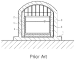
図1は、従来技術に係る陸上用液化ガス貯蔵タンクのうちフルコンテインメントタイプ(Full containment type)の例を示している。図1に示すように、陸上用液化ガス貯蔵タンクは、基礎1上にコンクリートを打設して形成された、略ドーム状の蓋を有する円筒状タンク本体3を含む。
FIG. 1 shows an example of a full containment type of a land-based liquefied gas storage tank according to the prior art. As shown in FIG. 1, the land-use liquefied gas storage tank includes a
コンクリート製のタンク本体3の内部には断熱底4及び断熱壁5が設置され、この断熱底4及び断熱壁5とタンク本体3との間にはガス密封壁2が設置される。一方、断熱底4及び断熱壁5の内部には、極低温状態の液化ガスを密封状態で収容可能なコンテナ6が積層・設置される。
A
コンテナ6は、液化ガスが直接的に接する部分であるので、極低温に耐えられる低温炭素材などの素材で製作され、ガス密封壁2は、一般の炭素鋼などの素材で製作される。
Since the container 6 is a part in direct contact with the liquefied gas, the container 6 is made of a material such as a low-temperature carbon material that can withstand extremely low temperatures, and the
しかしながら、前記のように構成される従来の陸上用液化ガス貯蔵タンクにおいては、まず、基礎工事を実施した後、この基礎1上に設置された鋳型にコンクリートを流し込んで一定の高さにまで壁体を製作し、コンクリートが完全に固まり、壁体が所定の強度を有するようになった後、再び一定の高さにまで壁体を製作する過程を繰り返して円筒状のタンク本体3を製作するので、かなりの時間を要するという問題があった。
However, in the conventional liquefied gas storage tank for land constructed as described above, first, after the foundation work is carried out, the concrete is poured into the mold installed on the foundation 1 and the walls are fixed to a certain height. After the body is completely solidified and the wall body has a predetermined strength, the process of producing the wall body to a certain height is repeated to manufacture the
前記のような従来の問題点を解決するために、本発明は、予め製作された複数の単位壁構造物を積み上げることにより、円筒状の貯蔵タンクの側壁部を迅速かつ容易に製作することができる陸上用液化ガス貯蔵タンクの製作方法を提供する。 In order to solve the conventional problems as described above, the present invention can quickly and easily manufacture a side wall portion of a cylindrical storage tank by stacking a plurality of unit wall structures manufactured in advance. A method for manufacturing a liquefied gas storage tank for land is provided.
上記の目的を達成するための本発明の一態様によれば、陸上で液化ガスを貯蔵するための陸上用液化ガス貯蔵タンクを製作する方法は、内部に縦横に鉄筋が配列されたコンクリート製の単位壁構造物を製作する工程と、製作された前記単位壁構造物を円筒状に積層する工程と、貯蔵タンクの壁体を形成するために、上下左右に隣接する各単位壁構造物を互いに連結する工程とを含む。 According to one aspect of the present invention for achieving the above object, a method for producing a land-based liquefied gas storage tank for storing liquefied gas on land is made of concrete, in which reinforcing bars are arranged vertically and horizontally. In order to form a unit wall structure, a step of laminating the manufactured unit wall structures in a cylindrical shape, and a wall of a storage tank, the unit wall structures adjacent to each other vertically and horizontally are connected to each other. Connecting.
前記単位壁構造物の上下左右の面には溝部が形成され、前記単位壁構造物を積層する工程では、前記溝部に嵌め込まれる位置決めブロックを挟んで前記単位壁構造物を積層することによって、積層と同時に位置決めを行うことが望ましい。 Grooves are formed on the top, bottom, left, and right surfaces of the unit wall structure, and in the step of stacking the unit wall structures, the unit wall structures are stacked by sandwiching the positioning blocks fitted into the groove parts. It is desirable to perform positioning at the same time.
前記鉄筋は、前記単位壁構造物の上下左右の面から突出するように配列され、前記単位壁構造物を連結する工程では、前記単位壁構造物の面から露出した前記鉄筋を、上下左右に隣接する単位壁構造物の鉄筋と連結することが望ましい。 The reinforcing bars are arranged so as to protrude from the upper, lower, left and right surfaces of the unit wall structure, and in the step of connecting the unit wall structures, the reinforcing bars exposed from the surface of the unit wall structure are It is desirable to connect with the rebar of the adjacent unit wall structure.
前記鉄筋は、複数の貫通穴が形成されている鉄筋連結板を介して連結されることが望ましい。 The reinforcing bars are preferably connected via a reinforcing bar connecting plate in which a plurality of through holes are formed.
前記鉄筋を連結した後、前記単位壁構造物の前面同士を連結すると同時に、前記単位壁構造物の後面同士を連結することが望ましい。 After connecting the reinforcing bars, it is desirable to connect the front surfaces of the unit wall structures together with the rear surfaces of the unit wall structures.
前記単位壁構造物の前面同士は前方連結板を介して連結され、前記単位壁構造物の後面同士は後方連結板を介して連結されることが望ましい。 Preferably, the front surfaces of the unit wall structures are connected to each other through a front connection plate, and the rear surfaces of the unit wall structures are connected to each other through a rear connection plate.
前記鉄筋を連結した後、前記単位壁構造物の間の空間にコンクリートを打設し、前記単位壁構造物を一体化することが望ましい。 After connecting the reinforcing bars, it is preferable to put concrete in a space between the unit wall structures to integrate the unit wall structures.
前記単位壁構造物の一つの側面には密封層が設置されてもよく、前記単位壁構造物を連結する工程は、それぞれの単位壁構造物に設置された前記密封層を互いに連結する工程を含んでもよい。 A sealing layer may be installed on one side surface of the unit wall structure, and the step of connecting the unit wall structures includes a step of connecting the sealing layers installed on the unit wall structures to each other. May be included.
本発明の方法は、前記単位壁構造物を積層する工程の前に、基礎工事を実施して基礎を形成する工程をさらに含み、前記単位壁構造物を連結する工程の後に、蓋を設置して貯蔵タンクのタンク本体を完成する工程をさらに含むことが望ましい。 The method of the present invention further includes a step of performing foundation work to form a foundation before the step of laminating the unit wall structures, and a lid is installed after the step of connecting the unit wall structures. Preferably, the method further includes a step of completing the tank body of the storage tank.
また、本発明の他の態様によれば、陸上で液化ガスを貯蔵するための陸上用液化ガス貯蔵タンクを製作する方法は、内部に縦横に鉄筋が配列され、該鉄筋の末端が面から突出した単位壁構造物を製作する工程と、前記鉄筋の末端が互いに接触しないように、製作された前記単位壁構造物を互いに離して積層する工程と、上下左右に隣接する単位壁構造物の鉄筋同士を連結する工程とを含む。 According to another aspect of the present invention, there is provided a method for producing a land-use liquefied gas storage tank for storing liquefied gas on land, in which reinforcing bars are arranged vertically and horizontally, and the ends of the reinforcing bars protrude from the surface. Manufacturing the unit wall structure, stacking the manufactured unit wall structures apart from each other so that the ends of the reinforcing bars do not contact each other, and reinforcing bars of the unit wall structure adjacent to each other vertically and horizontally And connecting them together.
また、本発明の更に他の態様によれば、陸上で液化ガスを貯蔵するための陸上用液化ガス貯蔵タンクを製作する方法は、内部に縦横に鉄筋が配列された単位壁構造物を製作する工程と、前記単位壁構造物を互いに離して積層する工程と、積層された前記単位壁構造物の間にコンクリートを打設し、前記単位壁構造物を一体化する工程とを含む。 According to still another aspect of the present invention, a method for manufacturing a land-based liquefied gas storage tank for storing liquefied gas on land includes a unit wall structure in which reinforcing bars are arranged vertically and horizontally. And a step of laminating the unit wall structures apart from each other, and placing concrete between the laminated unit wall structures to integrate the unit wall structures.
上述したような本発明によって、予め製作された複数の単位壁構造物を積み上げることにより、円筒状の貯蔵タンクの側壁部を迅速かつ容易に製作することができる陸上用液化ガス貯蔵タンクの製作方法が提供される。 According to the present invention as described above, a method for producing a land-based liquefied gas storage tank capable of quickly and easily producing a side wall portion of a cylindrical storage tank by stacking a plurality of unit wall structures produced in advance. Is provided.
したがって、本発明の陸上用液化ガス貯蔵タンクの製作方法によって、陸上用液化ガス貯蔵タンクの製作に必要な時間を従来に比べて著しく節減することができ、その結果、工期短縮による費用節減が可能になる。 Therefore, the liquefied gas storage tank manufacturing method of the present invention can significantly reduce the time required for manufacturing the liquefied gas storage tank for land compared to the conventional method, and as a result, the cost can be reduced by shortening the construction period. become.
以下、添付の図面を参照して、本発明に係る陸上用液化ガス貯蔵タンクの製作方法と、本発明の製作方法で使用する単位壁構造物について詳細に説明する。 Hereinafter, with reference to the accompanying drawings, a method for manufacturing a liquefied gas storage tank for land according to the present invention and a unit wall structure used in the manufacturing method according to the present invention will be described in detail.
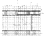
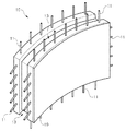
図2は、本発明による、陸上用液化ガス貯蔵タンクを製作するための単位壁構造物の断面図で、図3は、本発明による単位壁構造物を積み上げて製作した陸上用液化ガス貯蔵タンクの側壁部の一部を示した図で、図4は、本発明による、陸上用液化ガス貯蔵タンクを製作するための単位壁構造物の斜視図で、図5は、高さ調節が可能な位置決めブロックの側面図である。 FIG. 2 is a cross-sectional view of a unit wall structure for manufacturing a land liquefied gas storage tank according to the present invention, and FIG. 3 is a land liquefied gas storage tank manufactured by stacking unit wall structures according to the present invention. FIG. 4 is a perspective view of a unit wall structure for manufacturing a land-based liquefied gas storage tank according to the present invention, and FIG. 5 is a view showing height adjustment. It is a side view of a positioning block.
図2〜図4に示すように、本発明に係る陸上用液化ガス貯蔵タンクは、多数の単位壁構造物10を略円筒状に積み上げることによって製作される。それぞれの単位壁構造物10は、内部に縦横に鉄筋11が配列された略六面体状のコンクリート壁体からなる。
As shown in FIGS. 2 to 4, the liquefied gas storage tank for land according to the present invention is manufactured by stacking a large number of
単位壁構造物10を積み上げて形成される貯蔵タンクの壁面は円筒状であるため、それぞれの単位壁構造物10は、図4に示すように、丸みを帯びた略円弧状であることが望ましい。ただし、貯蔵タンクの半径が各単位壁構造物の幅に比べて非常に大きいため、単位壁構造物は略六面体状であるものとして説明する。
Since the wall surface of the storage tank formed by stacking the
各単位壁構造物10の上下左右の面には溝部13が形成され、この溝部13には、単位壁構造物10を所定の位置に積み上げるための位置決めブロック21が配置される。位置決めブロック21により、単位壁構造物10を積み上げるときに正確に所定の位置にそれぞれの単位壁構造物10が配置される。左右方向に隣接する各単位壁構造物10を整列させるために、左右に隣接する各単位壁構造物10の間にも、位置決めブロック21と同様に、ブロック(図示せず)を配置してもよい。
単位壁構造物10内に縦横に配列される鉄筋11は、前方(図2で見ると左側)と後方(図2で見ると右側)にそれぞれ1セットずつ、合計2セットが内蔵されることが望ましく、鉄筋11の末端は、単位壁構造物10の上下左右の面から突出している。
The
したがって、図4に示すように、鉄筋11の末端は、単位壁構造物10の上下左右の面からそれぞれ2列突出している。特に、図2及び図4に示すように、単位壁構造物10の上下の面から上下方向に突出する鉄筋11は、位置決めブロック21が配置される溝部13に対してさらに前面側又は後面側に位置していることが望ましい。
Therefore, as shown in FIG. 4, the ends of the
隣接する単位壁構造物の突出した鉄筋は、それぞれ鉄筋連結板23を介して連結され、その結果、隣接する単位壁構造物が互いに固定される。鉄筋連結板23を介して連結するために、例えば、溶接などの作業が行われる。
The protruding reinforcing bars of the adjacent unit wall structures are connected to each other via the reinforcing
予め製作された単位壁構造物を現場で組み立てるとき、最も考慮すべきことは、鉄筋の連続性(応力集中が発生しないように設計)と施工性(単位壁構造物の鉄筋同士を連結する方法)である。本発明の発明者らは、前記のような点を勘案した上で、隣接する単位壁構造物の露出した鉄筋同士を鉄筋連結板23によって連結することによって鉄筋の連続性と施工性のいずれも満足できるようにした。
When assembling prefabricated unit wall structures on site, the most important points to consider are the continuity of the reinforcing bars (designed so that stress concentration does not occur) and the workability (method of connecting the reinforcing bars of the unit wall structures to each other) ). The inventors of the present invention consider both the above points and connect the exposed reinforcing bars of adjacent unit wall structures to each other by the reinforcing
鉄筋連結板23は、一つの鉄板が上下又は左右の隣接する単位壁構造物から露出した鉄筋11同士を連結するような構成であってよい。また、鉄筋連結板23は、一対の鉄板をそれぞれ片側の鉄筋11のみを連結するように取り付けた後、続けて隣接する各鉄板をシーム溶接して互いに連結するような構成であってもよい。例えば、それぞれの単位壁構造物10において、露出した鉄筋11に鉄板を取り付けた後、この鉄板を隣接する他の単位壁構造物10の露出した鉄筋11に取り付けた鉄板にシーム溶接して連結することができる。即ち、鉄筋連結板23は、一つの単位壁構造物10の露出した鉄筋11に取り付けた鉄板と、他の単位壁構造物10の露出した鉄筋11に取り付けた鉄板とを互いに連結するように構成することもできる。
The reinforcing
ここで、位置決めブロック21を挟んで単位壁構造物10を積層するとき、上下に隣接する単位壁構造物10の面から突出する鉄筋11の末端が互いに接触しないように位置決めブロック21の高さが決定されることが望ましい。
Here, when the
施工現場で発生する誤差を補正するために、位置決めブロック21は、図5に示すように、傾斜面を境界にして上部ブロック21aと下部ブロック21bに分けられる。単位壁構造物10を積層するとき、設計時より施工時の単位壁構造物10の積層高さが低い場合、図5の実線で示すように、上部ブロック21aを傾斜面に沿って下側(図5で見ると左側)に少し移動させることによって位置決めブロック21の高さを低くする。その一方、単位壁構造物10を積層するとき、設計時より施工時の単位壁構造物10の積層高さが高い場合、図5の点線で示すように、上部ブロック21aを傾斜面に沿って上側(図5で見ると右側)に少し移動させることによって位置決めブロック21の高さを高くする。
In order to correct an error occurring at the construction site, the
鉄筋連結板23によって隣接する各単位壁構造物10を互いに連結した後、鉄筋11と鉄筋連結板23が露出しないように各単位壁構造物10の間の空間にはコンクリートが打設されることが望ましい。その結果、円筒状の壁体全体が一つに連結される。
After the adjacent
コンクリートの打設時に鋳型の役割をするように、隣接する単位壁構造物10の前面と後面にはそれぞれ、隣接する前面同士を互いに連結する前方連結板25と、隣接する後面同士を互いに連結する後方連結板27が設置される。
The front connecting
前方連結板25と後方連結板27の設置を溶接によって容易に行えるように、単位壁構造物10は、その上下左右の面が金属素材の枠体15で囲まれていることが望ましい。
The
また、鉄筋連結板23の内側にまでコンクリートが容易に打設されるように、鉄筋連結板23には複数の貫通穴23aが形成されることが望ましい。
鉄筋連結板23、前方連結板25及び後方連結板27は、上下に隣接する各単位壁構造物10を連結するときに使用されるとともに、左右に隣接する各単位壁構造物10を連結するときにも使用される。
Further, it is desirable that a plurality of through holes 23 a be formed in the reinforcing
The reinforcing
このように、本発明によれば、上下左右に隣接する各単位壁構造物10を鉄筋連結板23、前方連結板25及び後方連結板27によって連結すると同時に、隣接する各単位壁構造物10の間にコンクリートを打設することによって全ての単位壁構造物10を一体化することができる。その結果、円筒状の貯蔵タンクの壁体全体を一体化することができ、充分な強度を得るようになる。
As described above, according to the present invention, the
一方、図4の点線で示すように、単位壁構造物10の後面、すなわち、貯蔵タンクの内面にはガスを遮断する密封層19(すなわち、ガスバリアとしてのガス密封壁)が取り付けられる。このように密封層19を取り付けた状態で単位壁構造物10を製作すれば、貯蔵タンクの壁体を完成した後、密封層を別途積層する必要がなく、単位壁構造物10を円筒状に積み上げた後、互いに連結することによって貯蔵タンクの壁体を完成できるので有利である。
On the other hand, as shown by a dotted line in FIG. 4, a sealing layer 19 (that is, a gas sealing wall as a gas barrier) that blocks gas is attached to the rear surface of the
以下、図2〜図4を参照して、本発明に係る陸上用液化ガス貯蔵タンクの製作方法を説明する。 Hereinafter, with reference to FIGS. 2-4, the manufacturing method of the liquefied gas storage tank for land based on this invention is demonstrated.
本発明の陸上用液化ガス貯蔵タンクの製作方法は、略六面体状のコンクリート製の単位壁構造物10を製作する工程と、予め製作された単位壁構造物10を円筒状に積層する工程と、隣接する各単位壁構造物10を互いに連結する工程とを含む。
The method for producing a land-use liquefied gas storage tank of the present invention includes a step of producing a substantially hexahedral concrete
上述したように、単位壁構造物10は、内部に縦横に鉄筋11が配列された状態でコンクリートを打設することによって製作される。このとき、単位壁構造物10の上下左右の面には溝部13が形成されることが望ましく、一つの側面(すなわち、完成した貯蔵タンクの内面)には密封層19が設置される。
As described above, the
単位壁構造物10を円筒状に積層するときには、上下の面に形成された溝部13に一つ以上の位置決めブロック21を配置して、これを上下方向に隣接する各単位壁構造物10で挟む。その結果、単位壁構造物10の位置決めが確実かつ自然に行われる。
When the
引き続いて、積層された単位壁構造物10の露出した鉄筋11を、上下左右に隣接する各単位壁構造物10の鉄筋11と鉄筋連結板23を介して連結する。このとき、鉄筋11と鉄筋連結板23は、溶接などの方法によって一体に連結することができる。
Subsequently, the exposed reinforcing
また、積層された単位壁構造物10の各前面を前方連結板25によって互いに連結し、積層された単位壁構造物10の各後面を後方連結板27によって互いに連結する。
Further, the front surfaces of the stacked
その次に、上下左右に隣接する各単位壁構造物10の間の空間にコンクリートを打設することによって、積層された各単位壁構造物10を互いに完璧に連結して一体化する。
Next, by placing concrete in the space between the
一方、各単位壁構造物10を円筒状に積層する前に、地面に基礎工事を実施し、平らな基礎を形成することが望ましい。また、各単位壁構造物10を積層して互いに連結した後、蓋を設置する作業を実施することによって貯蔵タンクのタンク本体を完成し、内部に断熱壁と密封壁などを設置することによって液化ガス貯蔵タンクを完成する。
On the other hand, before laminating the
図4に示すように、単位壁構造物10に密封層19が取り付けられている場合は、タンク本体を完成した後、密封壁を設置する作業を別途行う必要がなく、積層された単位壁構造物10を連結しながら密封壁を同時に形成することができる。
As shown in FIG. 4, when the
このように、本発明によれば、コンクリート製の単位壁構造物を積層・設置し、これら各単位壁構造物の間に現場でコンクリートを打設することによって貯蔵タンクの壁体を完成することができる。その結果、貯蔵タンクの建設工期を短縮しながらも、各単位壁構造物の接合剤としてコンクリートを使用し、それぞれの単位壁構造物をより堅固に一体化できるようになる。 As described above, according to the present invention, the wall of the storage tank is completed by stacking and installing concrete unit wall structures and placing concrete on-site between these unit wall structures. Can do. As a result, while shortening the construction period of the storage tank, concrete can be used as a bonding agent for each unit wall structure, and the unit wall structures can be more firmly integrated.
以上、添付の図面を参照して本発明に係る陸上用液化ガス貯蔵タンクの製作方法を説明したが、本発明は、以上説明した実施例及び図面によって限定されるものでなく、特許請求の範囲内で本発明の属する技術分野における通常の知識を有する者によって多様な修正及び変形が可能であることは当然である。 As mentioned above, although the manufacturing method of the liquefied gas storage tank for land based on this invention was demonstrated with reference to attached drawing, this invention is not limited by the Example and drawing which were demonstrated above, Claims Of course, various modifications and variations can be made by those having ordinary knowledge in the technical field to which the present invention pertains.
10:単位壁構造物、11:鉄筋、13:溝部、15:枠体、19:密封層、21:位置決めブロック、23:鉄筋連結板、23a:貫通穴、25:前方連結板、27:後方連結板 10: unit wall structure, 11: reinforcing bar, 13: groove, 15: frame, 19: sealing layer, 21: positioning block, 23: reinforcing bar connecting plate, 23a: through hole, 25: front connecting plate, 27: rear Connecting plate
Claims (8)
内部に縦横に鉄筋が配列されたコンクリート製の単位壁構造物を製作する工程と、
製作された前記単位壁構造物を円筒状に積層する工程と、
貯蔵タンクの壁体を形成するために、上下左右に隣接する各単位壁構造物を互いに連結する工程とを含む陸上用液化ガス貯蔵タンクの製作方法において、
前記単位壁構造物の上下左右の面には溝部が形成され、
前記単位壁構造物を積層する工程では、前記溝部に嵌め込まれる位置決めブロックを挟んで前記単位壁構造物を積層することによって、積層と同時に位置決めを行うことを特徴とする陸上用液化ガス貯蔵タンクの製作方法。 A method for producing a land-based liquefied gas storage tank for storing liquefied gas on land,
A process of manufacturing a unit wall structure made of concrete in which reinforcing bars are arranged vertically and horizontally;
A step of laminating the manufactured unit wall structure into a cylindrical shape;
In a method for producing a land-use liquefied gas storage tank including a step of connecting unit wall structures adjacent to each other vertically and horizontally to form a wall of the storage tank,
Grooves are formed on the upper, lower, left and right surfaces of the unit wall structure,
In the step of laminating the unit wall structure, the unit wall structure is laminated by sandwiching a positioning block fitted in the groove portion, thereby performing positioning at the same time as the laminating liquefied gas storage tank. Production method.
前記単位壁構造物を連結する工程では、前記単位壁構造物の面から露出した前記鉄筋を、上下左右に隣接する単位壁構造物の鉄筋と連結することを特徴とする、請求項1に記載の陸上用液化ガス貯蔵タンクの製作方法。 The reinforcing bars are arranged so as to protrude from the upper, lower, left and right surfaces of the unit wall structure,
2. The step of connecting the unit wall structures includes connecting the reinforcing bars exposed from the surface of the unit wall structure with reinforcing bars of the unit wall structures adjacent vertically and horizontally. Method of liquefied gas storage tank for terrestrial use.
前記単位壁構造物を連結する工程は、それぞれの単位壁構造物に設置された前記密封層を互いに連結する工程を含むことを特徴とする、請求項1に記載の陸上用液化ガス貯蔵タンクの製作方法。 A sealing layer is installed on one side of the unit wall structure,
The liquefied gas storage tank for land according to claim 1, wherein the step of connecting the unit wall structures includes a step of connecting the sealing layers installed in the unit wall structures to each other. Production method.
前記単位壁構造物を連結する工程の後に、蓋を設置して貯蔵タンクのタンク本体を完成する工程をさらに含むことを特徴とする、請求項1に記載の陸上用液化ガス貯蔵タンクの製作方法。 Before the step of laminating the unit wall structure, further comprising the step of performing foundation work to form a foundation,
The method for manufacturing a land-based liquefied gas storage tank according to claim 1, further comprising a step of completing a tank body of the storage tank by installing a lid after the step of connecting the unit wall structures. .
Applications Claiming Priority (2)
| Application Number | Priority Date | Filing Date | Title |
|---|---|---|---|
| KR1020090106530A KR100964824B1 (en) | 2009-11-05 | 2009-11-05 | Method for building a liquefied gas storage tank |
| KR10-2009-0106530 | 2009-11-05 |
Publications (2)
| Publication Number | Publication Date |
|---|---|
| JP2011099550A JP2011099550A (en) | 2011-05-19 |
| JP5049331B2 true JP5049331B2 (en) | 2012-10-17 |
Family
ID=42370255
Family Applications (1)
| Application Number | Title | Priority Date | Filing Date |
|---|---|---|---|
| JP2009268228A Active JP5049331B2 (en) | 2009-11-05 | 2009-11-26 | Production method of liquefied gas storage tank for land |
Country Status (5)
| Country | Link |
|---|---|
| US (1) | US8627636B2 (en) |
| EP (1) | EP2320122B1 (en) |
| JP (1) | JP5049331B2 (en) |
| KR (1) | KR100964824B1 (en) |
| CN (1) | CN102051992B (en) |
Families Citing this family (10)
| Publication number | Priority date | Publication date | Assignee | Title |
|---|---|---|---|---|
| CN102792084B (en) * | 2010-03-17 | 2014-11-26 | 气体产品与化学公司 | Cryogenic storage tank |
| JP5998616B2 (en) * | 2012-04-26 | 2016-09-28 | 株式会社Ihi | Independent liner unit and tank construction method |
| CN103741980B (en) * | 2012-10-17 | 2016-04-20 | 重庆宇冠数控科技有限公司 | The design and manufaction of rectangle or rectangle ultra-large type LNG storage tank |
| CN103758387B (en) * | 2014-02-19 | 2016-02-10 | 中国海洋石油总公司 | The mounting method of liquefied natural gas (LNG) tank wallboard |
| JP5837118B2 (en) * | 2014-03-14 | 2015-12-24 | 鹿島建設株式会社 | Construction method of tank and breakwater |
| JP6421433B2 (en) * | 2014-04-04 | 2018-11-14 | 株式会社Ihi | Precast block connection method and prestress tank using the same |
| US9284114B2 (en) * | 2014-08-18 | 2016-03-15 | Chevron U.S.A. Inc. | Method of construction of prestressed concrete panel wall liquid storage tank and tank so constructed |
| JP5791777B1 (en) | 2014-11-06 | 2015-10-07 | 鹿島建設株式会社 | Joining structure and joining method |
| FR3052229B1 (en) * | 2016-06-01 | 2018-07-06 | Gaztransport Et Technigaz | SEALED AND THERMALLY INSULATING TANK INTEGRATED IN A POLYEDRIAL CARRIER STRUCTURE |
| FR3102531B1 (en) * | 2019-10-24 | 2021-11-12 | Ifp Energies Now | Energy storage tank in the form of pressurized gas, made of ultra-high performance fiber-reinforced concrete |
Family Cites Families (29)
| Publication number | Priority date | Publication date | Assignee | Title |
|---|---|---|---|---|
| US1050130A (en) * | 1912-05-03 | 1913-01-14 | George C Harvey | Concrete structure. |
| GB191517719A (en) * | 1915-12-18 | 1916-12-18 | Evan Owen Williams | Improvements in the Construction of Reinforced Concrete Tanks, Tuns, Bins, Silos, Vessels and the like. |
| US1452583A (en) * | 1921-05-09 | 1923-04-24 | Walter J Williams | Interlocking fire brick for arches |
| US2501951A (en) * | 1945-07-24 | 1950-03-28 | Lintz Mark | Construction of tanks, silos, and like vessels |
| FR1006081A (en) * | 1947-11-10 | 1952-04-18 | Improvements made to removable constructions such as chimneys, silos, etc. | |
| GB718606A (en) | 1951-10-08 | 1954-11-17 | Wilfrid Cracroft Ash | An improved storage tank for liquids and a method of constructing same |
| US3300943A (en) * | 1964-04-29 | 1967-01-31 | Albert C Racine | Building system |
| US4006570A (en) * | 1974-04-01 | 1977-02-08 | Stolz Owen M | Wall structure and manufacturing method therefor |
| JPS5916625B2 (en) * | 1976-09-30 | 1984-04-17 | 石川島建材工業株式会社 | How to build an underground tank |
| CH624789A5 (en) * | 1977-07-05 | 1981-08-14 | Foerderung Forschung Gmbh | |
| JPS54141511U (en) * | 1978-03-25 | 1979-10-01 | ||
| JPS56120900A (en) | 1980-02-25 | 1981-09-22 | Toyo Kanetsu Kk | Double shell low temperature liquid storage tank |
| US5038540A (en) * | 1981-11-20 | 1991-08-13 | Krautz Alfons O | Sectional smokestack |
| JPS58214093A (en) | 1982-06-05 | 1983-12-13 | Kawasaki Heavy Ind Ltd | Double shell type low temperature tank |
| FR2539792B1 (en) * | 1983-01-26 | 1985-11-15 | Matiere Marcel | METHOD FOR CONSTRUCTING WATERPROOF STRUCTURES, SUCH AS TANKS |
| JPS60175668A (en) * | 1984-02-21 | 1985-09-09 | 川崎重工業株式会社 | Construction of cylindrical tank |
| FR2658228B1 (en) * | 1990-02-14 | 1992-06-05 | Lachize Claudius | PROCESS FOR CONSTRUCTING REINFORCED CONCRETE TANKS, PREFABRICATED ELEMENTS FOR IMPLEMENTING SAID METHOD AND MACHINE FOR PRODUCING THE SAME. |
| JP3111282B2 (en) * | 1990-08-31 | 2000-11-20 | 株式会社石井鐵工所 | Prefabricated concrete storage tank |
| JP3407026B2 (en) * | 1993-06-11 | 2003-05-19 | 株式会社竹中工務店 | Segment for shield method for underground tank construction and underground tank for storage of LNG etc. |
| CN2270083Y (en) * | 1996-05-03 | 1997-12-10 | 洪文章 | Quick removing and assembling type fireproof movable partition wall |
| US6041561A (en) * | 1997-08-22 | 2000-03-28 | Wayne Leblang | Self-contained molded pre-fabricated building panel and method of making the same |
| KR100375501B1 (en) | 1999-05-25 | 2003-03-10 | 주식회사 한국화이바 | liquefied natural gas lang storage tank side wall structure and method |
| IL141467A0 (en) * | 2001-02-15 | 2002-03-10 | Industrial walls | |
| JP2004106884A (en) | 2002-09-18 | 2004-04-08 | Shimizu Corp | Construction method for tank sidewall |
| US7162844B2 (en) * | 2003-01-09 | 2007-01-16 | Chicago Bridge & Iron Company | Use of partial precast panels for construction of concrete walls and shells |
| KR100589527B1 (en) * | 2003-01-25 | 2006-06-15 | 유천만 | protection wall for concrete pre cast purification tank |
| KR100430862B1 (en) | 2003-09-16 | 2004-05-10 | 주식회사 한텍 | Method for constructing of liquefied gas storage tank |
| US7555872B1 (en) * | 2005-01-04 | 2009-07-07 | Jeffrey Beach | Spacer for aligning concrete blocks |
| KR100964825B1 (en) | 2009-11-05 | 2010-06-24 | 한국가스공사 | Wall structure for building a liquefied gas storage tank |
-
2009
- 2009-11-05 KR KR1020090106530A patent/KR100964824B1/en active IP Right Grant
- 2009-11-25 EP EP09177104.8A patent/EP2320122B1/en active Active
- 2009-11-25 CN CN2009102462057A patent/CN102051992B/en active Active
- 2009-11-26 JP JP2009268228A patent/JP5049331B2/en active Active
- 2009-11-30 US US12/627,969 patent/US8627636B2/en not_active Expired - Fee Related
Also Published As
| Publication number | Publication date |
|---|---|
| CN102051992A (en) | 2011-05-11 |
| EP2320122A3 (en) | 2017-05-10 |
| JP2011099550A (en) | 2011-05-19 |
| US20110099940A1 (en) | 2011-05-05 |
| US8627636B2 (en) | 2014-01-14 |
| KR100964824B1 (en) | 2010-06-23 |
| EP2320122A2 (en) | 2011-05-11 |
| EP2320122B1 (en) | 2020-09-09 |
| CN102051992B (en) | 2013-11-13 |
Similar Documents
| Publication | Publication Date | Title |
|---|---|---|
| JP5049331B2 (en) | Production method of liquefied gas storage tank for land | |
| JP4987948B2 (en) | Unit wall structure for the production of liquefied gas storage tanks for terrestrial use | |
| US10533707B2 (en) | Ground liquefied natural gas storage tank and method for manufacturing the same | |
| CN105263797B (en) | The cargo hold of cryogenic material carrier | |
| CA2840062C (en) | Method for constructing low-temperature tank and low-temperature tank | |
| WO2011020999A2 (en) | Improved hatchcover | |
| JP5074702B2 (en) | Anchor member assembly | |
| KR101141972B1 (en) | Method for constructing side wall of storage tank for liquefied natural gas(lng) using rebar panel | |
| JP6546069B2 (en) | Construction method of double shell low temperature storage tank | |
| JP3111282B2 (en) | Prefabricated concrete storage tank | |
| CN102019512B (en) | Butt welding construction method for T-shaped column | |
| KR101540848B1 (en) | Aboveground type liquid storage tank | |
| JP5672787B2 (en) | Construction method of cylindrical tank | |
| KR101978405B1 (en) | Method for building a liquefied gas storage tank | |
| JP5236796B2 (en) | Anchor member assembly | |
| CN212452727U (en) | Large-volume cast-in-situ special-shaped concrete bearing platform | |
| CN108735316B (en) | Stainless steel boron aluminum composite board for storage cells of VVER fuel assembly and manufacturing method | |
| JP2023122758A (en) | Low temperature liquefied gas tank and construction method of the same | |
| KR101540850B1 (en) | Aboveground type liquid storage tank | |
| WO2022177446A1 (en) | Cellular pressure vessel, method for fabrication and use thereof | |
| KR101540849B1 (en) | Aboveground type liquid storage tank | |
| GB2593254A (en) | A method of manufacturing a dome and a dome manufactured using the method | |
| KR101437745B1 (en) | Aboveground type liquid storage tank and method for constructing there of | |
| CN106894648A (en) | A kind of prefabricated assembling type reinforced concrete frame structure bracing reinforcement node component |
Legal Events
| Date | Code | Title | Description |
|---|---|---|---|
| A131 | Notification of reasons for refusal |
Free format text: JAPANESE INTERMEDIATE CODE: A131 Effective date: 20120117 |
|
| A521 | Request for written amendment filed |
Free format text: JAPANESE INTERMEDIATE CODE: A523 Effective date: 20120412 |
|
| TRDD | Decision of grant or rejection written | ||
| A01 | Written decision to grant a patent or to grant a registration (utility model) |
Free format text: JAPANESE INTERMEDIATE CODE: A01 Effective date: 20120703 |
|
| A01 | Written decision to grant a patent or to grant a registration (utility model) |
Free format text: JAPANESE INTERMEDIATE CODE: A01 |
|
| A61 | First payment of annual fees (during grant procedure) |
Free format text: JAPANESE INTERMEDIATE CODE: A61 Effective date: 20120720 |
|
| FPAY | Renewal fee payment (event date is renewal date of database) |
Free format text: PAYMENT UNTIL: 20150727 Year of fee payment: 3 |
|
| R150 | Certificate of patent or registration of utility model |
Ref document number: 5049331 Country of ref document: JP Free format text: JAPANESE INTERMEDIATE CODE: R150 Free format text: JAPANESE INTERMEDIATE CODE: R150 |
|
| R250 | Receipt of annual fees |
Free format text: JAPANESE INTERMEDIATE CODE: R250 |
|
| R250 | Receipt of annual fees |
Free format text: JAPANESE INTERMEDIATE CODE: R250 |
|
| R250 | Receipt of annual fees |
Free format text: JAPANESE INTERMEDIATE CODE: R250 |
|
| R250 | Receipt of annual fees |
Free format text: JAPANESE INTERMEDIATE CODE: R250 |
|
| R250 | Receipt of annual fees |
Free format text: JAPANESE INTERMEDIATE CODE: R250 |
|
| R250 | Receipt of annual fees |
Free format text: JAPANESE INTERMEDIATE CODE: R250 |
|
| R250 | Receipt of annual fees |
Free format text: JAPANESE INTERMEDIATE CODE: R250 |
|
| R250 | Receipt of annual fees |
Free format text: JAPANESE INTERMEDIATE CODE: R250 |
|
| R250 | Receipt of annual fees |
Free format text: JAPANESE INTERMEDIATE CODE: R250 |