EP2320122A2 - Method of constructing liquefied gas storage tank on land - Google Patents
Method of constructing liquefied gas storage tank on land Download PDFInfo
- Publication number
- EP2320122A2 EP2320122A2 EP09177104A EP09177104A EP2320122A2 EP 2320122 A2 EP2320122 A2 EP 2320122A2 EP 09177104 A EP09177104 A EP 09177104A EP 09177104 A EP09177104 A EP 09177104A EP 2320122 A2 EP2320122 A2 EP 2320122A2
- Authority
- EP
- European Patent Office
- Prior art keywords
- unit
- wall structures
- wall
- storage tank
- iron rods
- Prior art date
- Legal status (The legal status is an assumption and is not a legal conclusion. Google has not performed a legal analysis and makes no representation as to the accuracy of the status listed.)
- Granted
Links
- 238000000034 method Methods 0.000 title claims abstract description 30
- XEEYBQQBJWHFJM-UHFFFAOYSA-N Iron Chemical compound [Fe] XEEYBQQBJWHFJM-UHFFFAOYSA-N 0.000 claims abstract description 117
- 229910052742 iron Inorganic materials 0.000 claims abstract description 58
- 238000007789 sealing Methods 0.000 claims description 13
- 238000005266 casting Methods 0.000 claims description 8
- 230000002452 interceptive effect Effects 0.000 claims description 3
- 238000010276 construction Methods 0.000 abstract description 12
- 239000007789 gas Substances 0.000 description 28
- 238000003466 welding Methods 0.000 description 4
- IJGRMHOSHXDMSA-UHFFFAOYSA-N Atomic nitrogen Chemical compound N#N IJGRMHOSHXDMSA-UHFFFAOYSA-N 0.000 description 2
- 230000004888 barrier function Effects 0.000 description 2
- 239000003949 liquefied natural gas Substances 0.000 description 2
- PMVSDNDAUGGCCE-TYYBGVCCSA-L Ferrous fumarate Chemical compound [Fe+2].[O-]C(=O)\C=C\C([O-])=O PMVSDNDAUGGCCE-TYYBGVCCSA-L 0.000 description 1
- QVGXLLKOCUKJST-UHFFFAOYSA-N atomic oxygen Chemical compound [O] QVGXLLKOCUKJST-UHFFFAOYSA-N 0.000 description 1
- 239000011230 binding agent Substances 0.000 description 1
- 239000003575 carbonaceous material Substances 0.000 description 1
- 239000000446 fuel Substances 0.000 description 1
- 238000009434 installation Methods 0.000 description 1
- 239000003915 liquefied petroleum gas Substances 0.000 description 1
- 239000002184 metal Substances 0.000 description 1
- 229910052751 metal Inorganic materials 0.000 description 1
- 229910052757 nitrogen Inorganic materials 0.000 description 1
- 239000001301 oxygen Substances 0.000 description 1
- 229910052760 oxygen Inorganic materials 0.000 description 1
- 230000002265 prevention Effects 0.000 description 1
Images


Classifications
-
- E—FIXED CONSTRUCTIONS
- E04—BUILDING
- E04H—BUILDINGS OR LIKE STRUCTURES FOR PARTICULAR PURPOSES; SWIMMING OR SPLASH BATHS OR POOLS; MASTS; FENCING; TENTS OR CANOPIES, IN GENERAL
- E04H7/00—Construction or assembling of bulk storage containers employing civil engineering techniques in situ or off the site
- E04H7/02—Containers for fluids or gases; Supports therefor
- E04H7/18—Containers for fluids or gases; Supports therefor mainly of concrete, e.g. reinforced concrete, or other stone-like material
-
- F—MECHANICAL ENGINEERING; LIGHTING; HEATING; WEAPONS; BLASTING
- F17—STORING OR DISTRIBUTING GASES OR LIQUIDS
- F17C—VESSELS FOR CONTAINING OR STORING COMPRESSED, LIQUEFIED OR SOLIDIFIED GASES; FIXED-CAPACITY GAS-HOLDERS; FILLING VESSELS WITH, OR DISCHARGING FROM VESSELS, COMPRESSED, LIQUEFIED, OR SOLIDIFIED GASES
- F17C1/00—Pressure vessels, e.g. gas cylinder, gas tank, replaceable cartridge
- F17C1/02—Pressure vessels, e.g. gas cylinder, gas tank, replaceable cartridge involving reinforcing arrangements
- F17C1/08—Integral reinforcements, e.g. ribs
-
- E—FIXED CONSTRUCTIONS
- E04—BUILDING
- E04B—GENERAL BUILDING CONSTRUCTIONS; WALLS, e.g. PARTITIONS; ROOFS; FLOORS; CEILINGS; INSULATION OR OTHER PROTECTION OF BUILDINGS
- E04B2/00—Walls, e.g. partitions, for buildings; Wall construction with regard to insulation; Connections specially adapted to walls
- E04B2/02—Walls, e.g. partitions, for buildings; Wall construction with regard to insulation; Connections specially adapted to walls built-up from layers of building elements
- E04B2/28—Walls having cavities between, but not in, the elements; Walls of elements each consisting of two or more parts kept in distance by means of spacers, all parts being solid
- E04B2/40—Walls having cavities between, but not in, the elements; Walls of elements each consisting of two or more parts kept in distance by means of spacers, all parts being solid the walls being characterised by fillings in all cavities in order to form a wall construction
-
- E—FIXED CONSTRUCTIONS
- E04—BUILDING
- E04B—GENERAL BUILDING CONSTRUCTIONS; WALLS, e.g. PARTITIONS; ROOFS; FLOORS; CEILINGS; INSULATION OR OTHER PROTECTION OF BUILDINGS
- E04B2/00—Walls, e.g. partitions, for buildings; Wall construction with regard to insulation; Connections specially adapted to walls
- E04B2/56—Load-bearing walls of framework or pillarwork; Walls incorporating load-bearing elongated members
- E04B2/64—Load-bearing walls of framework or pillarwork; Walls incorporating load-bearing elongated members with elongated members of concrete
- E04B2/68—Load-bearing walls of framework or pillarwork; Walls incorporating load-bearing elongated members with elongated members of concrete made by filling-up wall cavities
-
- F—MECHANICAL ENGINEERING; LIGHTING; HEATING; WEAPONS; BLASTING
- F17—STORING OR DISTRIBUTING GASES OR LIQUIDS
- F17C—VESSELS FOR CONTAINING OR STORING COMPRESSED, LIQUEFIED OR SOLIDIFIED GASES; FIXED-CAPACITY GAS-HOLDERS; FILLING VESSELS WITH, OR DISCHARGING FROM VESSELS, COMPRESSED, LIQUEFIED, OR SOLIDIFIED GASES
- F17C2201/00—Vessel construction, in particular geometry, arrangement or size
- F17C2201/01—Shape
- F17C2201/0104—Shape cylindrical
- F17C2201/0109—Shape cylindrical with exteriorly curved end-piece
-
- F—MECHANICAL ENGINEERING; LIGHTING; HEATING; WEAPONS; BLASTING
- F17—STORING OR DISTRIBUTING GASES OR LIQUIDS
- F17C—VESSELS FOR CONTAINING OR STORING COMPRESSED, LIQUEFIED OR SOLIDIFIED GASES; FIXED-CAPACITY GAS-HOLDERS; FILLING VESSELS WITH, OR DISCHARGING FROM VESSELS, COMPRESSED, LIQUEFIED, OR SOLIDIFIED GASES
- F17C2201/00—Vessel construction, in particular geometry, arrangement or size
- F17C2201/01—Shape
- F17C2201/0104—Shape cylindrical
- F17C2201/0119—Shape cylindrical with flat end-piece
-
- F—MECHANICAL ENGINEERING; LIGHTING; HEATING; WEAPONS; BLASTING
- F17—STORING OR DISTRIBUTING GASES OR LIQUIDS
- F17C—VESSELS FOR CONTAINING OR STORING COMPRESSED, LIQUEFIED OR SOLIDIFIED GASES; FIXED-CAPACITY GAS-HOLDERS; FILLING VESSELS WITH, OR DISCHARGING FROM VESSELS, COMPRESSED, LIQUEFIED, OR SOLIDIFIED GASES
- F17C2201/00—Vessel construction, in particular geometry, arrangement or size
- F17C2201/03—Orientation
- F17C2201/032—Orientation with substantially vertical main axis
-
- F—MECHANICAL ENGINEERING; LIGHTING; HEATING; WEAPONS; BLASTING
- F17—STORING OR DISTRIBUTING GASES OR LIQUIDS
- F17C—VESSELS FOR CONTAINING OR STORING COMPRESSED, LIQUEFIED OR SOLIDIFIED GASES; FIXED-CAPACITY GAS-HOLDERS; FILLING VESSELS WITH, OR DISCHARGING FROM VESSELS, COMPRESSED, LIQUEFIED, OR SOLIDIFIED GASES
- F17C2201/00—Vessel construction, in particular geometry, arrangement or size
- F17C2201/05—Size
- F17C2201/052—Size large (>1000 m3)
-
- F—MECHANICAL ENGINEERING; LIGHTING; HEATING; WEAPONS; BLASTING
- F17—STORING OR DISTRIBUTING GASES OR LIQUIDS
- F17C—VESSELS FOR CONTAINING OR STORING COMPRESSED, LIQUEFIED OR SOLIDIFIED GASES; FIXED-CAPACITY GAS-HOLDERS; FILLING VESSELS WITH, OR DISCHARGING FROM VESSELS, COMPRESSED, LIQUEFIED, OR SOLIDIFIED GASES
- F17C2203/00—Vessel construction, in particular walls or details thereof
- F17C2203/01—Reinforcing or suspension means
- F17C2203/011—Reinforcing means
- F17C2203/012—Reinforcing means on or in the wall, e.g. ribs
Definitions
- the present disclosure relates to a method of constructing a liquefied gas storage tank on land and, more particularly, to a method of constructing a liquefied gas storage tank on land, which enables rapid and easy construction of a cylindrical wall of the storage tank by stacking a plurality of pre-produced unit-wall structures to overlap one another.
- a liquefied gas storage tank on land has a substantially cylindrical flat bottom and is used to store liquefied gas for fuels, such as liquefied natural gas (LNG), liquefied petroleum gas, and the like, and other liquefied gases such as liquefied oxygen, liquefied nitrogen, and the like.
- LNG liquefied natural gas
- liquefied petroleum gas liquefied petroleum gas
- other liquefied gases such as liquefied oxygen, liquefied nitrogen, and the like.
- Figure 1 shows one example of a conventional full-containment type liquefied gas storage tank on land.
- the liquefied gas storage tank includes a cylindrical tank body 3 formed through concrete casting on a foundation 1 and having an approximately dome-shaped cover.
- the tank body 3 which is made of concrete, is provided therein with a heat insulating bottom 4 and a heat insulating wall 5, and a vapor barrier 2 is interposed between the tank body 3 and the heat insulating bottom 4 and between the tank body 3 and the heat insulating wall 5.
- a container 6 is located inside the heat insulating bottom 4 and the heat insulating wall 5, to contain a cryogenic liquefied gas in a sealed state.
- the container 6 directly contacts the liquefied gas, it may be made of a low-temperature carbon material or the like, which is capable of enduring cryogenic conditions.
- Such a conventional liquefied gas storage tank is generally constructed to have the cylindrical tank body 3 by performing foundation work and repeating a process of pouring concrete into a mould on the foundation 1 to produce one wall having a predetermined height and a process of re-pouring the concrete into the mould to produce another wall of a predetermined height on the one wall after the one wall is completely hardened to have predetermined strength. Accordingly, the conventional liquefied gas storage tank has a problem in that considerable time is consumed for construction thereof.
- the present disclosure is directed to solving the problems of the related art as described above, and one embodiment includes a method of constructing a liquefied gas storage tank on land, which enables rapid and easy construction of a cylindrical wall of the storage tank by stacking a plurality of pre-produced unit-wall structures to overlap one another.
- a method of constructing a liquefied gas storage tank on land includes: producing unit-wall structures made of concrete and each having iron rods arranged lengthwise and breadthwise therein; stacking the unit-wall structures in a cylindrical arrangement; and connecting the unit-wall structures adjacent in vertical and lateral directions to each other to form a wall of the storage tank.
- Each of the unit-wall structures may have grooves on upper, lower, left and right surfaces thereof, and the stacking of the unit-wall structures may include interposing a positioning block between the unit-wall structures to be fitted into the groove to allow the unit-wall structures to be located in place when the unit-wall structures are stacked.
- the iron rods may be arranged to protrude from upper, lower, left and right surfaces of the unit-wall structures, and the connecting of the unit-wall structures may include connecting the protruded iron rods of each of the unit-wall structures to those of other unit-wall structures adjacent thereto in the vertical and lateral directions.
- the iron rods may be connected to each other through an iron rod plate having a plurality of through-holes.
- the connecting of the unit-wall structures may further include connecting front sides of the unit-wall structures to each other while connecting rear sides of the unit-wall structures to each other, after connecting the iron rods.
- the front sides of the unit-wall structures may be connected to each other through a front side connecting plate and the rear sides of the unit-wall structures may be connected to each other through a rear side connecting plate.
- the method may further include casting the concrete into a space between the unit-wall structures to integrate the unit-wall structures with each other after connecting the iron rods.
- Each of the unit-wall structures may be provided at one side thereof with a sealing layer, and the connecting of the unit-wall structures may include connecting the sealing layers of the respective unit-wall structures to each other.
- the method may further include performing foundation work to form a foundation before stacking the unit-wall structures; and placing a cover to complete a tank body of the storage tank after connecting the unit-wall structures.
- a method of constructing a liquefied gas storage tank on land includes: producing unit-wall structures each having iron rods arranged lengthwise and breadthwise therein, each of the iron rods having distal ends exposed from surfaces of the unit-wall structure; stacking the produced unit-wall structures to be separated from each other while preventing the distal ends of the iron rods from interfering with each other; and connecting the iron rods of unit-wall structures adjacent in vertical and lateral directions to each other.
- a method of constructing a liquefied gas storage tank on land includes: producing unit-wall structures, each having iron rods arranged lengthwise and breadthwise therein; stacking the produced unit-wall structures to be separated from each other; and casting concrete in a space between the unit-wall structures to integrate the unit-wall structures with each other.
- a liquefied gas storage tank on land in accordance with one embodiment is constructed by stacking a plurality of unit-wall structures 10 in an approximately cylindrical arrangement.
- Each of the unit-wall structures 10 is made of concrete and has a parallelepiped shape wherein iron rods 11 are arranged lengthwise and breadthwise.
- each of the unit-wall structures 10 may be rounded to have a substantially arc shape as shown in Figure 4 .
- the unit-wall structure will be described as having a substantially parallelepiped shape hereinafter.
- Each of the unit-wall structures 10 has grooves 13 on upper, lower, left and right surfaces thereof so that a positioning block 21 is disposed on each of the grooves 13 to stack the unit-wall structures 10 in place.
- the positioning blocks 21 allow each of the unit-wall structures 10 to be accurately located in place when the unit-wall structures 10 are stacked.
- a block (not shown) may be interposed between the unit-wall structures 10 adjacent to each other in a lateral direction to align the adjacent unit-wall structures 10 with each other.
- each of the unit-wall structures 10 two sets of iron rods 11 are arranged lengthwise and breadthwise, such that one set of iron rods 11 is assigned to the front side (left side in Figure 2 ) of the unit-wall structure 10 and the other set is assigned to the rear side thereof. Distal ends of the iron rods 11 protrude from upper, lower, left and right surfaces of the unit-wall structure 10.
- the distal ends of the iron cores 11 may protrude from the upper, lower, left and right surfaces of the unit-wall structure 10 to be arranged in two rows, as shown in Figure 4 .
- the iron rods 11 protruding from the upper and lower surfaces of the unit-wall structure 10 in the vertical direction may be further biased toward the front side or the rear side of the unit-wall structure 10 than the grooves 13 on which the positioning blocks 21 will be disposed.
- the protruded iron rods of the adjacent unit-wall structures may be connected to one another by iron rod connecting plates 23, so that the adjacent unit-wall structures are secured to each other.
- welding may be performed.
- the exposed iron rods of the adjacent unit-wall structures are connected to each other by the iron rod connecting plates 23, thereby satisfying both continuity and constructability of the iron rods.
- the iron rod connecting plate 23 may be configured to allow one iron plate to connect the iron rods 11 which are exposed from the unit-wall structures 10 adjacent to each other in the vertical or lateral direction.
- the iron rod connecting plate 23 may be configured to allow a pair of iron plates, which are attached to each other and joined to other adjacent iron plates by line-welding, to connect only the iron rods 11 to each other at one side of the unit-wall structure.
- the height of the positioning block 21 may be determined so as to prevent the distal ends of the iron rods 11 protruding from the surfaces of the unit-wall structures 10 adjacent to each other in the vertical direction from interfering with each other.
- the positioning block 21 may be divided into upper and lower blocks 21a and 21b with a slanted plane provided as a border therebetween, as shown in Figure 5 . If the unit-wall structures 10 are stacked in actual construction to a height less than the design, the upper block 21a is slightly moved downward (to the left side in Figure 5 ) along the slanted plane as indicated by a solid line in Figure 5 to lower the height of the positioning block 21.
- the upper block 21a is slightly moved upward (to the right side in Figure 5 ) along the slanted plane as indicated by a dotted line in Figure 5 to increase the height of the positioning block 21.
- a front side connecting plate 25 and a rear side connecting plate 27 may be provided to front and rear sides of the adjacent unit-wall structures 10 to connect the adjacent front sides to each other and connect the adjacent rear sides to each other, respectively, while serving as moulds for casting concrete.
- the upper, lower, left and right surfaces of the unit-wall structures 10 may be surrounded by a metal frame 15.
- the iron rod connecting plate 23 may be formed with a plurality of through-holes 23a through which the concrete can be easily cast into the iron rod connecting plate 23.
- the iron rod connecting plate 23, the front side connecting plate 25, and the rear side connecting plate 27 can be used not only for connecting the unit-wall structures adjacent to each other in the vertical direction but also for connecting the unit-wall structures adjacent to each other in the lateral direction.
- all of the unit-wall structures 10 may be integrated to construct the integral cylindrical wall of the storage tank while ensuring sufficient strength by casting the concrete in the space between the adjacent unit-wall structures 10 while connecting the adjacent unit-wall structures to one another in the vertical and lateral directions using the iron rod connecting plate 23, the front side connecting plate 25, and the rear side connecting plate 27.
- a sealing layer 19, that is, a gas sealing wall acting as a gas barrier, may be attached to the rear side of the unit-wall structure 10, that is, an interior surface of the storage tank, to shield gas leakage.
- the wall of the storage tank can be advantageously constructed by stacking the unit-wall structures 10 in a cylindrical arrangement and connecting them to one another without separately stacking the sealing layers after constructing the wall of the storage tank.
- the method may include producing substantially parallelepiped unit-wall structures 10 using concrete, stacking the unit-wall structures 10 in a cylindrical arrangement, and connecting the adjacent unit-wall structures 10 to one another.
- each of the unit-wall structures 10 may be produced by casting concrete into a mould with iron rods 11 arranged lengthwise and breadthwise.
- the unit-wall structure 10 may have grooves 13 on upper, lower, left and right surfaces thereof, and may be provided with a sealing layer 19 at one side thereof, that is, an inner surface of the completed storage tank.
- one or more positioning blocks 21 are disposed on the grooves 13, which are formed on the upper and lower surfaces of the unit-wall structure 10, to be interposed between the unit-wall structures 10 adjacent to each other in the vertical direction. With this configuration, positioning of the unit-wall structures 10 may be securely and conveniently achieved.
- iron rods 11 of each unit-wall structure 10 are connected to those of other unit-wall structures 10 adjacent thereto in the vertical and lateral directions through iron rod connecting plates 23.
- the iron rods 11 and the iron rod connecting plates 23 may be integrally joined by welding or the like.
- adjacent front sides of the stacked unit-wall structures 10 are connected to each other by front side connecting plates 25, and adjacent rear sides of the stacked unit-wall structures 10 are connected to each other by rear side connecting plates 27.
- foundation work may be performed on the ground to form a flat foundation before stacking the unit-wall structures 10 in the cylindrical arrangement. Further, after stacking and connecting the unit-wall structures 10 to one another, operation of installing a cover is performed to complete a tank body of the storage tank, and a heat insulating wall and a sealing wall are disposed inside the tank body, thereby completing the liquefied gas storage tank.
- the sealing wall may be formed while connecting the stacked unit-wall structures 10 without a separate operation of installing the sealing wall after completing the tank body.
- the pre-produced unit-wall structures made of concrete are stacked and concrete is then cast into spaces between the unit-wall structures at a construction site, thereby constructing the wall of the storage tank.
- the respective unit-wall structures can be more strongly integrated with one another using concrete as a binder of the unit-wall structures while reducing time consumed for construction of the storage tank.
- the method according to the embodiments enables rapid and easy construction of a cylindrical wall of a liquefied gas storage tank by stacking a plurality of pre-produced unit-wall structures to overlap one another.
- the method according to the embodiments enables a considerable reduction in time for construction of the liquefied gas storage tank on land, thereby reducing construction costs.
Abstract
Description
- This application claims priority from and the benefit of Korean Patent Application No.
10-2009-0106530, filed on November 5, 2009 - The present disclosure relates to a method of constructing a liquefied gas storage tank on land and, more particularly, to a method of constructing a liquefied gas storage tank on land, which enables rapid and easy construction of a cylindrical wall of the storage tank by stacking a plurality of pre-produced unit-wall structures to overlap one another.
- Generally, a liquefied gas storage tank on land has a substantially cylindrical flat bottom and is used to store liquefied gas for fuels, such as liquefied natural gas (LNG), liquefied petroleum gas, and the like, and other liquefied gases such as liquefied oxygen, liquefied nitrogen, and the like. One example of such a cylindrical liquefied gas storage tank is disclosed in Japanese Patent Laid-open Publication No.
Sho 56-120900 -
Figure 1 shows one example of a conventional full-containment type liquefied gas storage tank on land. Referring toFigure 1 , the liquefied gas storage tank includes acylindrical tank body 3 formed through concrete casting on afoundation 1 and having an approximately dome-shaped cover. - The
tank body 3, which is made of concrete, is provided therein with aheat insulating bottom 4 and aheat insulating wall 5, and avapor barrier 2 is interposed between thetank body 3 and theheat insulating bottom 4 and between thetank body 3 and theheat insulating wall 5. Inside theheat insulating bottom 4 and theheat insulating wall 5, acontainer 6 is located to contain a cryogenic liquefied gas in a sealed state. - Since the
container 6 directly contacts the liquefied gas, it may be made of a low-temperature carbon material or the like, which is capable of enduring cryogenic conditions. - Such a conventional liquefied gas storage tank is generally constructed to have the
cylindrical tank body 3 by performing foundation work and repeating a process of pouring concrete into a mould on thefoundation 1 to produce one wall having a predetermined height and a process of re-pouring the concrete into the mould to produce another wall of a predetermined height on the one wall after the one wall is completely hardened to have predetermined strength. Accordingly, the conventional liquefied gas storage tank has a problem in that considerable time is consumed for construction thereof. - The present disclosure is directed to solving the problems of the related art as described above, and one embodiment includes a method of constructing a liquefied gas storage tank on land, which enables rapid and easy construction of a cylindrical wall of the storage tank by stacking a plurality of pre-produced unit-wall structures to overlap one another.
- In accordance with one aspect, a method of constructing a liquefied gas storage tank on land includes: producing unit-wall structures made of concrete and each having iron rods arranged lengthwise and breadthwise therein; stacking the unit-wall structures in a cylindrical arrangement; and connecting the unit-wall structures adjacent in vertical and lateral directions to each other to form a wall of the storage tank.
- Each of the unit-wall structures may have grooves on upper, lower, left and right surfaces thereof, and the stacking of the unit-wall structures may include interposing a positioning block between the unit-wall structures to be fitted into the groove to allow the unit-wall structures to be located in place when the unit-wall structures are stacked.
- The iron rods may be arranged to protrude from upper, lower, left and right surfaces of the unit-wall structures, and the connecting of the unit-wall structures may include connecting the protruded iron rods of each of the unit-wall structures to those of other unit-wall structures adjacent thereto in the vertical and lateral directions.
- The iron rods may be connected to each other through an iron rod plate having a plurality of through-holes.
- The connecting of the unit-wall structures may further include connecting front sides of the unit-wall structures to each other while connecting rear sides of the unit-wall structures to each other, after connecting the iron rods.
- The front sides of the unit-wall structures may be connected to each other through a front side connecting plate and the rear sides of the unit-wall structures may be connected to each other through a rear side connecting plate.
- The method may further include casting the concrete into a space between the unit-wall structures to integrate the unit-wall structures with each other after connecting the iron rods.
- Each of the unit-wall structures may be provided at one side thereof with a sealing layer, and the connecting of the unit-wall structures may include connecting the sealing layers of the respective unit-wall structures to each other.
- The method may further include performing foundation work to form a foundation before stacking the unit-wall structures; and placing a cover to complete a tank body of the storage tank after connecting the unit-wall structures.
- In accordance with another aspect, a method of constructing a liquefied gas storage tank on land includes: producing unit-wall structures each having iron rods arranged lengthwise and breadthwise therein, each of the iron rods having distal ends exposed from surfaces of the unit-wall structure; stacking the produced unit-wall structures to be separated from each other while preventing the distal ends of the iron rods from interfering with each other; and connecting the iron rods of unit-wall structures adjacent in vertical and lateral directions to each other.
- In accordance with a further aspect, a method of constructing a liquefied gas storage tank on land includes: producing unit-wall structures, each having iron rods arranged lengthwise and breadthwise therein; stacking the produced unit-wall structures to be separated from each other; and casting concrete in a space between the unit-wall structures to integrate the unit-wall structures with each other.
-
-
Figure 1 shows one example of a conventional full-containment type liquefied gas storage tank on land; -
Figure 2 is a cross-sectional view of a unit-wall structure for a liquefied gas storage tank in accordance with one embodiment of the present disclosure; -
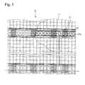
Figure 3 shows a part of a wall of the liquefied gas storage tank having the unit-wall structures stacked to overlap each other in accordance with the embodiment of the present disclosure; -
Figure 4 is a perspective view of the unit-wall structure for the liquefied gas storage tank in accordance with the embodiment of the present disclosure; and -
Figure 5 is a side view of a height-adjustable positioning block. - Embodiments of the present disclosure will now be described in detail with reference to the accompanying drawings.
- Referring to
Figures 2 to 4 , a liquefied gas storage tank on land in accordance with one embodiment is constructed by stacking a plurality of unit-wall structures 10 in an approximately cylindrical arrangement. Each of the unit-wall structures 10 is made of concrete and has a parallelepiped shape whereiniron rods 11 are arranged lengthwise and breadthwise. - Since the storage tank has a cylindrical wall formed by stacking the unit-
wall structures 10, each of the unit-wall structures 10 may be rounded to have a substantially arc shape as shown inFigure 4 . Here, since the storage tank has a much greater radius than the width of each of the unit-wall structures, the unit-wall structure will be described as having a substantially parallelepiped shape hereinafter. - Each of the unit-
wall structures 10 hasgrooves 13 on upper, lower, left and right surfaces thereof so that apositioning block 21 is disposed on each of thegrooves 13 to stack the unit-wall structures 10 in place. Thepositioning blocks 21 allow each of the unit-wall structures 10 to be accurately located in place when the unit-wall structures 10 are stacked. Similar to thepositioning block 21, a block (not shown) may be interposed between the unit-wall structures 10 adjacent to each other in a lateral direction to align the adjacent unit-wall structures 10 with each other. - In each of the unit-
wall structures 10, two sets ofiron rods 11 are arranged lengthwise and breadthwise, such that one set ofiron rods 11 is assigned to the front side (left side inFigure 2 ) of the unit-wall structure 10 and the other set is assigned to the rear side thereof. Distal ends of theiron rods 11 protrude from upper, lower, left and right surfaces of the unit-wall structure 10. - Thus, the distal ends of the
iron cores 11 may protrude from the upper, lower, left and right surfaces of the unit-wall structure 10 to be arranged in two rows, as shown inFigure 4 . Particularly, referring toFigures 2 and4 , theiron rods 11 protruding from the upper and lower surfaces of the unit-wall structure 10 in the vertical direction may be further biased toward the front side or the rear side of the unit-wall structure 10 than thegrooves 13 on which thepositioning blocks 21 will be disposed. - The protruded iron rods of the adjacent unit-wall structures may be connected to one another by iron
rod connecting plates 23, so that the adjacent unit-wall structures are secured to each other. To connect the iron rods to each other through the ironrod connecting plates 23, for example, welding may be performed. - When stacking the pre-produced unit-wall structures at field sites, it is important to consider continuity (that is, prevention of stress concentration) and constructability (that is, method of connecting the iron rods of the respective unit-wall structures to each other) of the iron rods. In the embodiment, the exposed iron rods of the adjacent unit-wall structures are connected to each other by the iron
rod connecting plates 23, thereby satisfying both continuity and constructability of the iron rods. - The iron
rod connecting plate 23 may be configured to allow one iron plate to connect theiron rods 11 which are exposed from the unit-wall structures 10 adjacent to each other in the vertical or lateral direction. Alternatively, the ironrod connecting plate 23 may be configured to allow a pair of iron plates, which are attached to each other and joined to other adjacent iron plates by line-welding, to connect only theiron rods 11 to each other at one side of the unit-wall structure. - Here, when the unit-
wall structures 10 are stacked with thepositioning block 21 interposed therebetween, the height of thepositioning block 21 may be determined so as to prevent the distal ends of theiron rods 11 protruding from the surfaces of the unit-wall structures 10 adjacent to each other in the vertical direction from interfering with each other. - In order to correct any possible error in a construction site, the
positioning block 21 may be divided into upper andlower blocks Figure 5 . If the unit-wall structures 10 are stacked in actual construction to a height less than the design, theupper block 21a is slightly moved downward (to the left side inFigure 5 ) along the slanted plane as indicated by a solid line inFigure 5 to lower the height of thepositioning block 21. On the contrary, if the unit-wall structures 10 are stacked in actual construction to a height greater than the design, theupper block 21a is slightly moved upward (to the right side inFigure 5 ) along the slanted plane as indicated by a dotted line inFigure 5 to increase the height of thepositioning block 21. - After the adjacent unit-
wall structures 10 are connected to each other by the ironrod connecting plates 23, concrete may be cast into a space between the unit-wall structures 10 to prevent theiron rods 11 and the ironrod connecting plates 11 from being exposed. With this configuration, all of the unit-wall structures can be connected to each other to construct the cylindrical wall of the storage tank. - A front
side connecting plate 25 and a rearside connecting plate 27 may be provided to front and rear sides of the adjacent unit-wall structures 10 to connect the adjacent front sides to each other and connect the adjacent rear sides to each other, respectively, while serving as moulds for casting concrete. - In order to facilitate installation of the front and rear
side connecting plates wall structures 10 may be surrounded by ametal frame 15. - Further, the iron
rod connecting plate 23 may be formed with a plurality of through-holes 23a through which the concrete can be easily cast into the ironrod connecting plate 23. - The iron
rod connecting plate 23, the frontside connecting plate 25, and the rearside connecting plate 27 can be used not only for connecting the unit-wall structures adjacent to each other in the vertical direction but also for connecting the unit-wall structures adjacent to each other in the lateral direction. - As such, according to the embodiment, all of the unit-
wall structures 10 may be integrated to construct the integral cylindrical wall of the storage tank while ensuring sufficient strength by casting the concrete in the space between the adjacent unit-wall structures 10 while connecting the adjacent unit-wall structures to one another in the vertical and lateral directions using the ironrod connecting plate 23, the frontside connecting plate 25, and the rearside connecting plate 27. - On the other hand, as shown in
Figure 4 , asealing layer 19, that is, a gas sealing wall acting as a gas barrier, may be attached to the rear side of the unit-wall structure 10, that is, an interior surface of the storage tank, to shield gas leakage. By producing the unit-wall structures with the sealing layers 19 attached thereto, the wall of the storage tank can be advantageously constructed by stacking the unit-wall structures 10 in a cylindrical arrangement and connecting them to one another without separately stacking the sealing layers after constructing the wall of the storage tank. - Next, a method of constructing a liquefied gas storage tank on land in accordance with one embodiment will be described with reference to
Figs. 2 to 4 . - In this embodiment, the method may include producing substantially parallelepiped unit-
wall structures 10 using concrete, stacking the unit-wall structures 10 in a cylindrical arrangement, and connecting the adjacent unit-wall structures 10 to one another. - As described above, each of the unit-
wall structures 10 may be produced by casting concrete into a mould withiron rods 11 arranged lengthwise and breadthwise. Here, the unit-wall structure 10 may havegrooves 13 on upper, lower, left and right surfaces thereof, and may be provided with asealing layer 19 at one side thereof, that is, an inner surface of the completed storage tank. - When stacking the unit-
wall structures 10 in the cylindrical arrangement, one or more positioning blocks 21 are disposed on thegrooves 13, which are formed on the upper and lower surfaces of the unit-wall structure 10, to be interposed between the unit-wall structures 10 adjacent to each other in the vertical direction. With this configuration, positioning of the unit-wall structures 10 may be securely and conveniently achieved. - Then, exposed
iron rods 11 of each unit-wall structure 10 are connected to those of other unit-wall structures 10 adjacent thereto in the vertical and lateral directions through ironrod connecting plates 23. Here, theiron rods 11 and the ironrod connecting plates 23 may be integrally joined by welding or the like. - Further, adjacent front sides of the stacked unit-
wall structures 10 are connected to each other by frontside connecting plates 25, and adjacent rear sides of the stacked unit-wall structures 10 are connected to each other by rearside connecting plates 27. - Then, concrete is cast into a space between the unit-
wall structures 10 adjacent to one another in the vertical and lateral directions, so that the stacked unit-wall structures 10 are completely connected and integrated. - On the other hand, foundation work may be performed on the ground to form a flat foundation before stacking the unit-
wall structures 10 in the cylindrical arrangement. Further, after stacking and connecting the unit-wall structures 10 to one another, operation of installing a cover is performed to complete a tank body of the storage tank, and a heat insulating wall and a sealing wall are disposed inside the tank body, thereby completing the liquefied gas storage tank. - When the
sealing layer 19 is attached to the unit-wall structure 10 as shown inFigure 4 , the sealing wall may be formed while connecting the stacked unit-wall structures 10 without a separate operation of installing the sealing wall after completing the tank body. - As such, in the method according to the embodiment, the pre-produced unit-wall structures made of concrete are stacked and concrete is then cast into spaces between the unit-wall structures at a construction site, thereby constructing the wall of the storage tank. As a result, the respective unit-wall structures can be more strongly integrated with one another using concrete as a binder of the unit-wall structures while reducing time consumed for construction of the storage tank.
- The method according to the embodiments enables rapid and easy construction of a cylindrical wall of a liquefied gas storage tank by stacking a plurality of pre-produced unit-wall structures to overlap one another.
- Therefore, the method according to the embodiments enables a considerable reduction in time for construction of the liquefied gas storage tank on land, thereby reducing construction costs.
- The various embodiments described above can be combined to provide further embodiments. All patents, patent application publications, patent applications, and non-patent publications referred to in this specification and/or listed in the Application Data Sheet are incorporated herein by reference, in their entirety. Aspects of the embodiments can be modified, if necessary, to employ concepts of the various patents, applications and publications to provide yet further embodiments.
- These and other changes can be made to the embodiments in light of the above-detailed description. In general, in the following claims, the terms used should not be construed to limit the claims to the specific embodiments disclosed in the specification and the claims, but should be construed to include all possible embodiments along with the full scope of equivalents to which such claims are entitled. Accordingly, the claims are not limited by the disclosure.
Claims (11)
- A method of constructing a liquefied gas storage tank on land, comprising:producing unit-wall structures (10) made of concrete and each having iron rods (11) arranged lengthwise and breadthwise therein;stacking the unit-wall structures (10) in a cylindrical arrangement; andconnecting the unit-wall structures(10) adjacent in vertical and lateral directions to each other to form a wall of the storage tank.
- The method according to claim 1, wherein each of the unit-wall structures has grooves (13) on upper, lower, left and right surfaces thereof, and the stacking the unit-wall structures comprises interposing a positioning block (21) between the unit-wall structures (10) to be fitted into the groove (13) to allow the unit-wall structures (10) to be located in place when the unit-wall structures are stacked.
- The method according to claim 1 or 2, wherein the iron rods (11) are arranged to protrude from upper, lower, left and right surfaces of the unit-wall structure (10), and the connecting the unit-wall structures (10) comprises connecting the protruded iron rods (11) of each of the unit-wall structures (10) to those of other unit-wall structures (10) adjacent thereto in the vertical and lateral directions.
- The method according to claim 3, wherein the iron rods (11) are connected to each other through an iron rod plate (23) having a plurality of through-holes (23a).
- The method according to claim 3, wherein the connecting the unit-wall structures further comprises connecting front sides of the unit-wall structures (10) to each other while connecting rear sides of the unit-wall structures (10) to each other, after connecting the iron rods (11).
- The method according to claim 5, wherein the front sides of the unit-wall structures (10) are connected to each other through a front side connecting plate (25) and the rear sides of the unit-wall structures (10) are connected to each other through a rear side connecting plate (27).
- The method according to claim 3, further comprising:casting the concrete into a space between the unit-wall structures (10) to integrate the unit-wall structures (10) with each other after connecting the iron rods (11).
- The method according to any one of claims 1 to 7, wherein each of the unit-wall structures (10) is provided at one side thereof with a sealing layer (19), and the connecting the unit-wall structures (10) comprises connecting the sealing layers (19) of the respective unit-wall structures (10) to each other.
- The method according to any one of claims 1 to 8, further comprising:performing foundation work to form a foundation before stacking the unit-wall structures; andplacing a cover to complete a tank body of the storage tank after connecting the unit-wall structures.
- A method of constructing a liquefied gas storage tank on land, comprising:producing unit-wall structures (10) each having iron rods (11) arranged lengthwise and breadthwise therein, each of the iron rods (11) having distal ends exposed from surfaces of the unit-wall structure;stacking the produced unit-wall structures (10) to be separated from each other while preventing the distal ends of the iron rods (11) from interfering with each other; andconnecting the iron rods (11) of the unit-wall structures (10) adjacent in vertical and lateral directions to each other.
- A method of constructing a liquefied gas storage tank on land, comprising:producing unit-wall structures (10), each having iron rods (11) arranged lengthwise and breadthwise therein;stacking the produced unit-wall structures (10) to be separated from each other; andcasting concrete in a space between the unit-wall structures (10) to integrate the unit-wall structures (10) with each other.
Applications Claiming Priority (1)
| Application Number | Priority Date | Filing Date | Title |
|---|---|---|---|
| KR1020090106530A KR100964824B1 (en) | 2009-11-05 | 2009-11-05 | Method for building a liquefied gas storage tank |
Publications (3)
| Publication Number | Publication Date |
|---|---|
| EP2320122A2 true EP2320122A2 (en) | 2011-05-11 |
| EP2320122A3 EP2320122A3 (en) | 2017-05-10 |
| EP2320122B1 EP2320122B1 (en) | 2020-09-09 |
Family
ID=42370255
Family Applications (1)
| Application Number | Title | Priority Date | Filing Date |
|---|---|---|---|
| EP09177104.8A Active EP2320122B1 (en) | 2009-11-05 | 2009-11-25 | Method of constructing liquefied gas storage tank on land |
Country Status (5)
| Country | Link |
|---|---|
| US (1) | US8627636B2 (en) |
| EP (1) | EP2320122B1 (en) |
| JP (1) | JP5049331B2 (en) |
| KR (1) | KR100964824B1 (en) |
| CN (1) | CN102051992B (en) |
Cited By (1)
| Publication number | Priority date | Publication date | Assignee | Title |
|---|---|---|---|---|
| CN103758387A (en) * | 2014-02-19 | 2014-04-30 | 中国海洋石油总公司 | Mounting method of liquefied natural gas storage tank wall plates |
Families Citing this family (9)
| Publication number | Priority date | Publication date | Assignee | Title |
|---|---|---|---|---|
| US8783501B2 (en) * | 2010-03-17 | 2014-07-22 | Air Products And Chemicals, Inc. | Cryogenic storage tank |
| JP5998616B2 (en) | 2012-04-26 | 2016-09-28 | 株式会社Ihi | Independent liner unit and tank construction method |
| CN103741980B (en) * | 2012-10-17 | 2016-04-20 | 重庆宇冠数控科技有限公司 | The design and manufaction of rectangle or rectangle ultra-large type LNG storage tank |
| JP5837118B2 (en) * | 2014-03-14 | 2015-12-24 | 鹿島建設株式会社 | Construction method of tank and breakwater |
| JP6421433B2 (en) * | 2014-04-04 | 2018-11-14 | 株式会社Ihi | Precast block connection method and prestress tank using the same |
| US9284114B2 (en) * | 2014-08-18 | 2016-03-15 | Chevron U.S.A. Inc. | Method of construction of prestressed concrete panel wall liquid storage tank and tank so constructed |
| JP5791777B1 (en) | 2014-11-06 | 2015-10-07 | 鹿島建設株式会社 | Joining structure and joining method |
| FR3052229B1 (en) * | 2016-06-01 | 2018-07-06 | Gaztransport Et Technigaz | SEALED AND THERMALLY INSULATING TANK INTEGRATED IN A POLYEDRIAL CARRIER STRUCTURE |
| FR3102531B1 (en) * | 2019-10-24 | 2021-11-12 | Ifp Energies Now | Energy storage tank in the form of pressurized gas, made of ultra-high performance fiber-reinforced concrete |
Citations (1)
| Publication number | Priority date | Publication date | Assignee | Title |
|---|---|---|---|---|
| JPS56120900A (en) | 1980-02-25 | 1981-09-22 | Toyo Kanetsu Kk | Double shell low temperature liquid storage tank |
Family Cites Families (28)
| Publication number | Priority date | Publication date | Assignee | Title |
|---|---|---|---|---|
| US1050130A (en) * | 1912-05-03 | 1913-01-14 | George C Harvey | Concrete structure. |
| GB191517719A (en) * | 1915-12-18 | 1916-12-18 | Evan Owen Williams | Improvements in the Construction of Reinforced Concrete Tanks, Tuns, Bins, Silos, Vessels and the like. |
| US1452583A (en) * | 1921-05-09 | 1923-04-24 | Walter J Williams | Interlocking fire brick for arches |
| US2501951A (en) * | 1945-07-24 | 1950-03-28 | Lintz Mark | Construction of tanks, silos, and like vessels |
| FR1006081A (en) * | 1947-11-10 | 1952-04-18 | Improvements made to removable constructions such as chimneys, silos, etc. | |
| GB718606A (en) | 1951-10-08 | 1954-11-17 | Wilfrid Cracroft Ash | An improved storage tank for liquids and a method of constructing same |
| US3300943A (en) * | 1964-04-29 | 1967-01-31 | Albert C Racine | Building system |
| US4006570A (en) * | 1974-04-01 | 1977-02-08 | Stolz Owen M | Wall structure and manufacturing method therefor |
| JPS5916625B2 (en) * | 1976-09-30 | 1984-04-17 | 石川島建材工業株式会社 | How to build an underground tank |
| CH624789A5 (en) * | 1977-07-05 | 1981-08-14 | Foerderung Forschung Gmbh | |
| JPS54141511U (en) * | 1978-03-25 | 1979-10-01 | ||
| US5038540A (en) * | 1981-11-20 | 1991-08-13 | Krautz Alfons O | Sectional smokestack |
| JPS58214093A (en) | 1982-06-05 | 1983-12-13 | Kawasaki Heavy Ind Ltd | Double shell type low temperature tank |
| FR2539792B1 (en) * | 1983-01-26 | 1985-11-15 | Matiere Marcel | METHOD FOR CONSTRUCTING WATERPROOF STRUCTURES, SUCH AS TANKS |
| JPS60175668A (en) * | 1984-02-21 | 1985-09-09 | 川崎重工業株式会社 | Construction of cylindrical tank |
| FR2658228B1 (en) * | 1990-02-14 | 1992-06-05 | Lachize Claudius | PROCESS FOR CONSTRUCTING REINFORCED CONCRETE TANKS, PREFABRICATED ELEMENTS FOR IMPLEMENTING SAID METHOD AND MACHINE FOR PRODUCING THE SAME. |
| JP3111282B2 (en) * | 1990-08-31 | 2000-11-20 | 株式会社石井鐵工所 | Prefabricated concrete storage tank |
| JP3407026B2 (en) * | 1993-06-11 | 2003-05-19 | 株式会社竹中工務店 | Segment for shield method for underground tank construction and underground tank for storage of LNG etc. |
| CN2270083Y (en) * | 1996-05-03 | 1997-12-10 | 洪文章 | Quick removing and assembling type fireproof movable partition wall |
| US6041561A (en) * | 1997-08-22 | 2000-03-28 | Wayne Leblang | Self-contained molded pre-fabricated building panel and method of making the same |
| KR100375501B1 (en) | 1999-05-25 | 2003-03-10 | 주식회사 한국화이바 | liquefied natural gas lang storage tank side wall structure and method |
| IL141467A0 (en) * | 2001-02-15 | 2002-03-10 | Industrial walls | |
| JP2004106884A (en) | 2002-09-18 | 2004-04-08 | Shimizu Corp | Construction method for tank sidewall |
| US7162844B2 (en) * | 2003-01-09 | 2007-01-16 | Chicago Bridge & Iron Company | Use of partial precast panels for construction of concrete walls and shells |
| KR100589527B1 (en) * | 2003-01-25 | 2006-06-15 | 유천만 | protection wall for concrete pre cast purification tank |
| KR100430862B1 (en) | 2003-09-16 | 2004-05-10 | 주식회사 한텍 | Method for constructing of liquefied gas storage tank |
| US7555872B1 (en) * | 2005-01-04 | 2009-07-07 | Jeffrey Beach | Spacer for aligning concrete blocks |
| KR100964825B1 (en) | 2009-11-05 | 2010-06-24 | 한국가스공사 | Wall structure for building a liquefied gas storage tank |
-
2009
- 2009-11-05 KR KR1020090106530A patent/KR100964824B1/en active IP Right Grant
- 2009-11-25 EP EP09177104.8A patent/EP2320122B1/en active Active
- 2009-11-25 CN CN2009102462057A patent/CN102051992B/en active Active
- 2009-11-26 JP JP2009268228A patent/JP5049331B2/en active Active
- 2009-11-30 US US12/627,969 patent/US8627636B2/en not_active Expired - Fee Related
Patent Citations (1)
| Publication number | Priority date | Publication date | Assignee | Title |
|---|---|---|---|---|
| JPS56120900A (en) | 1980-02-25 | 1981-09-22 | Toyo Kanetsu Kk | Double shell low temperature liquid storage tank |
Cited By (2)
| Publication number | Priority date | Publication date | Assignee | Title |
|---|---|---|---|---|
| CN103758387A (en) * | 2014-02-19 | 2014-04-30 | 中国海洋石油总公司 | Mounting method of liquefied natural gas storage tank wall plates |
| CN103758387B (en) * | 2014-02-19 | 2016-02-10 | 中国海洋石油总公司 | The mounting method of liquefied natural gas (LNG) tank wallboard |
Also Published As
| Publication number | Publication date |
|---|---|
| US20110099940A1 (en) | 2011-05-05 |
| US8627636B2 (en) | 2014-01-14 |
| JP5049331B2 (en) | 2012-10-17 |
| KR100964824B1 (en) | 2010-06-23 |
| EP2320122A3 (en) | 2017-05-10 |
| EP2320122B1 (en) | 2020-09-09 |
| CN102051992A (en) | 2011-05-11 |
| JP2011099550A (en) | 2011-05-19 |
| CN102051992B (en) | 2013-11-13 |
Similar Documents
| Publication | Publication Date | Title |
|---|---|---|
| EP2320122A2 (en) | Method of constructing liquefied gas storage tank on land | |
| US8656673B2 (en) | Wall structure for building a liquefied gas storage tank | |
| US9664338B2 (en) | Method for constructing low-temperature tank and low-temperature tank | |
| RU2511988C2 (en) | Polygonal reservoir for lng | |
| KR101884033B1 (en) | Cargo Tank for LNG Carrier | |
| JP2014205972A (en) | Method for constructing tank, and outer tank liner plate | |
| US20240084968A1 (en) | Tracing method for the construction of a liquefied gas storage installation comprising a polygonal bearing structure | |
| KR101973086B1 (en) | Cargo of liguefied natural gas and method for manufacturing thereof | |
| KR200480697Y1 (en) | reinforce structure for transformer tank | |
| JP2017089163A (en) | Building method of double-shell low-temperature storage tank | |
| KR100892306B1 (en) | Hybrid type pressure vessel | |
| KR101964638B1 (en) | Onshore membrane tank including embedded plate | |
| KR20140057102A (en) | Hangar of nuclear power plant in ocean and construction method of hangar | |
| JP2016020597A (en) | Construction method of tank and dike | |
| JP2007085115A (en) | Tub having side wall composed of construction material having strength | |
| KR20150069749A (en) | Membrane of lng cargo tank | |
| KR20190105185A (en) | Small size cng storage tank | |
| JP5672787B2 (en) | Construction method of cylindrical tank | |
| KR102513006B1 (en) | Plug install structure of insulation storage tank | |
| JP5940359B2 (en) | Construction method of vertical tank | |
| JP2020101241A (en) | Double shell tank | |
| JP6164549B2 (en) | Filling material for underground water tank | |
| JPH028197B2 (en) | ||
| KR20120064022A (en) | Lead battery |
Legal Events
| Date | Code | Title | Description |
|---|---|---|---|
| PUAI | Public reference made under article 153(3) epc to a published international application that has entered the european phase |
Free format text: ORIGINAL CODE: 0009012 |
|
| AK | Designated contracting states |
Kind code of ref document: A2 Designated state(s): AT BE BG CH CY CZ DE DK EE ES FI FR GB GR HR HU IE IS IT LI LT LU LV MC MK MT NL NO PL PT RO SE SI SK SM TR |
|
| AX | Request for extension of the european patent |
Extension state: AL BA RS |
|
| PUAL | Search report despatched |
Free format text: ORIGINAL CODE: 0009013 |
|
| AK | Designated contracting states |
Kind code of ref document: A3 Designated state(s): AT BE BG CH CY CZ DE DK EE ES FI FR GB GR HR HU IE IS IT LI LT LU LV MC MK MT NL NO PL PT RO SE SI SK SM TR |
|
| AX | Request for extension of the european patent |
Extension state: AL BA RS |
|
| RIC1 | Information provided on ipc code assigned before grant |
Ipc: E04H 7/18 20060101ALI20170405BHEP Ipc: F17C 1/08 20060101AFI20170405BHEP Ipc: E04B 2/40 20060101ALI20170405BHEP Ipc: E04B 2/68 20060101ALI20170405BHEP |
|
| STAA | Information on the status of an ep patent application or granted ep patent |
Free format text: STATUS: REQUEST FOR EXAMINATION WAS MADE |
|
| 17P | Request for examination filed |
Effective date: 20171110 |
|
| RBV | Designated contracting states (corrected) |
Designated state(s): AT BE BG CH CY CZ DE DK EE ES FI FR GB GR HR HU IE IS IT LI LT LU LV MC MK MT NL NO PL PT RO SE SI SK SM TR |
|
| STAA | Information on the status of an ep patent application or granted ep patent |
Free format text: STATUS: EXAMINATION IS IN PROGRESS |
|
| 17Q | First examination report despatched |
Effective date: 20180222 |
|
| GRAP | Despatch of communication of intention to grant a patent |
Free format text: ORIGINAL CODE: EPIDOSNIGR1 |
|
| STAA | Information on the status of an ep patent application or granted ep patent |
Free format text: STATUS: GRANT OF PATENT IS INTENDED |
|
| INTG | Intention to grant announced |
Effective date: 20200408 |
|
| RIN1 | Information on inventor provided before grant (corrected) |
Inventor name: YOON, IHN SOO Inventor name: SEO, HEUNG SEOK Inventor name: KIM, YOUNG KYUN Inventor name: YANG, YOUNG MYUNG |
|
| GRAS | Grant fee paid |
Free format text: ORIGINAL CODE: EPIDOSNIGR3 |
|
| GRAA | (expected) grant |
Free format text: ORIGINAL CODE: 0009210 |
|
| STAA | Information on the status of an ep patent application or granted ep patent |
Free format text: STATUS: THE PATENT HAS BEEN GRANTED |
|
| AK | Designated contracting states |
Kind code of ref document: B1 Designated state(s): AT BE BG CH CY CZ DE DK EE ES FI FR GB GR HR HU IE IS IT LI LT LU LV MC MK MT NL NO PL PT RO SE SI SK SM TR |
|
| REG | Reference to a national code |
Ref country code: GB Ref legal event code: FG4D |
|
| REG | Reference to a national code |
Ref country code: AT Ref legal event code: REF Ref document number: 1312006 Country of ref document: AT Kind code of ref document: T Effective date: 20200915 Ref country code: CH Ref legal event code: EP |
|
| REG | Reference to a national code |
Ref country code: IE Ref legal event code: FG4D |
|
| REG | Reference to a national code |
Ref country code: DE Ref legal event code: R096 Ref document number: 602009062737 Country of ref document: DE |
|
| REG | Reference to a national code |
Ref country code: LT Ref legal event code: MG4D |
|
| PG25 | Lapsed in a contracting state [announced via postgrant information from national office to epo] |
Ref country code: FI Free format text: LAPSE BECAUSE OF FAILURE TO SUBMIT A TRANSLATION OF THE DESCRIPTION OR TO PAY THE FEE WITHIN THE PRESCRIBED TIME-LIMIT Effective date: 20200909 Ref country code: GR Free format text: LAPSE BECAUSE OF FAILURE TO SUBMIT A TRANSLATION OF THE DESCRIPTION OR TO PAY THE FEE WITHIN THE PRESCRIBED TIME-LIMIT Effective date: 20201210 Ref country code: HR Free format text: LAPSE BECAUSE OF FAILURE TO SUBMIT A TRANSLATION OF THE DESCRIPTION OR TO PAY THE FEE WITHIN THE PRESCRIBED TIME-LIMIT Effective date: 20200909 Ref country code: BG Free format text: LAPSE BECAUSE OF FAILURE TO SUBMIT A TRANSLATION OF THE DESCRIPTION OR TO PAY THE FEE WITHIN THE PRESCRIBED TIME-LIMIT Effective date: 20201209 Ref country code: SE Free format text: LAPSE BECAUSE OF FAILURE TO SUBMIT A TRANSLATION OF THE DESCRIPTION OR TO PAY THE FEE WITHIN THE PRESCRIBED TIME-LIMIT Effective date: 20200909 Ref country code: NO Free format text: LAPSE BECAUSE OF FAILURE TO SUBMIT A TRANSLATION OF THE DESCRIPTION OR TO PAY THE FEE WITHIN THE PRESCRIBED TIME-LIMIT Effective date: 20201209 Ref country code: LT Free format text: LAPSE BECAUSE OF FAILURE TO SUBMIT A TRANSLATION OF THE DESCRIPTION OR TO PAY THE FEE WITHIN THE PRESCRIBED TIME-LIMIT Effective date: 20200909 |
|
| REG | Reference to a national code |
Ref country code: AT Ref legal event code: MK05 Ref document number: 1312006 Country of ref document: AT Kind code of ref document: T Effective date: 20200909 |
|
| REG | Reference to a national code |
Ref country code: NL Ref legal event code: MP Effective date: 20200909 |
|
| PG25 | Lapsed in a contracting state [announced via postgrant information from national office to epo] |
Ref country code: PL Free format text: LAPSE BECAUSE OF FAILURE TO SUBMIT A TRANSLATION OF THE DESCRIPTION OR TO PAY THE FEE WITHIN THE PRESCRIBED TIME-LIMIT Effective date: 20200909 Ref country code: LV Free format text: LAPSE BECAUSE OF FAILURE TO SUBMIT A TRANSLATION OF THE DESCRIPTION OR TO PAY THE FEE WITHIN THE PRESCRIBED TIME-LIMIT Effective date: 20200909 |
|
| PG25 | Lapsed in a contracting state [announced via postgrant information from national office to epo] |
Ref country code: PT Free format text: LAPSE BECAUSE OF FAILURE TO SUBMIT A TRANSLATION OF THE DESCRIPTION OR TO PAY THE FEE WITHIN THE PRESCRIBED TIME-LIMIT Effective date: 20210111 Ref country code: NL Free format text: LAPSE BECAUSE OF FAILURE TO SUBMIT A TRANSLATION OF THE DESCRIPTION OR TO PAY THE FEE WITHIN THE PRESCRIBED TIME-LIMIT Effective date: 20200909 Ref country code: SM Free format text: LAPSE BECAUSE OF FAILURE TO SUBMIT A TRANSLATION OF THE DESCRIPTION OR TO PAY THE FEE WITHIN THE PRESCRIBED TIME-LIMIT Effective date: 20200909 Ref country code: RO Free format text: LAPSE BECAUSE OF FAILURE TO SUBMIT A TRANSLATION OF THE DESCRIPTION OR TO PAY THE FEE WITHIN THE PRESCRIBED TIME-LIMIT Effective date: 20200909 Ref country code: CZ Free format text: LAPSE BECAUSE OF FAILURE TO SUBMIT A TRANSLATION OF THE DESCRIPTION OR TO PAY THE FEE WITHIN THE PRESCRIBED TIME-LIMIT Effective date: 20200909 Ref country code: EE Free format text: LAPSE BECAUSE OF FAILURE TO SUBMIT A TRANSLATION OF THE DESCRIPTION OR TO PAY THE FEE WITHIN THE PRESCRIBED TIME-LIMIT Effective date: 20200909 |
|
| PG25 | Lapsed in a contracting state [announced via postgrant information from national office to epo] |
Ref country code: ES Free format text: LAPSE BECAUSE OF FAILURE TO SUBMIT A TRANSLATION OF THE DESCRIPTION OR TO PAY THE FEE WITHIN THE PRESCRIBED TIME-LIMIT Effective date: 20200909 Ref country code: IS Free format text: LAPSE BECAUSE OF FAILURE TO SUBMIT A TRANSLATION OF THE DESCRIPTION OR TO PAY THE FEE WITHIN THE PRESCRIBED TIME-LIMIT Effective date: 20210109 Ref country code: AT Free format text: LAPSE BECAUSE OF FAILURE TO SUBMIT A TRANSLATION OF THE DESCRIPTION OR TO PAY THE FEE WITHIN THE PRESCRIBED TIME-LIMIT Effective date: 20200909 |
|
| REG | Reference to a national code |
Ref country code: DE Ref legal event code: R119 Ref document number: 602009062737 Country of ref document: DE |
|
| PG25 | Lapsed in a contracting state [announced via postgrant information from national office to epo] |
Ref country code: MC Free format text: LAPSE BECAUSE OF FAILURE TO SUBMIT A TRANSLATION OF THE DESCRIPTION OR TO PAY THE FEE WITHIN THE PRESCRIBED TIME-LIMIT Effective date: 20200909 Ref country code: SK Free format text: LAPSE BECAUSE OF FAILURE TO SUBMIT A TRANSLATION OF THE DESCRIPTION OR TO PAY THE FEE WITHIN THE PRESCRIBED TIME-LIMIT Effective date: 20200909 |
|
| REG | Reference to a national code |
Ref country code: CH Ref legal event code: PL |
|
| PLBE | No opposition filed within time limit |
Free format text: ORIGINAL CODE: 0009261 |
|
| STAA | Information on the status of an ep patent application or granted ep patent |
Free format text: STATUS: NO OPPOSITION FILED WITHIN TIME LIMIT |
|
| PG25 | Lapsed in a contracting state [announced via postgrant information from national office to epo] |
Ref country code: LU Free format text: LAPSE BECAUSE OF NON-PAYMENT OF DUE FEES Effective date: 20201125 |
|
| REG | Reference to a national code |
Ref country code: BE Ref legal event code: MM Effective date: 20201130 |
|
| 26N | No opposition filed |
Effective date: 20210610 |
|
| GBPC | Gb: european patent ceased through non-payment of renewal fee |
Effective date: 20201209 |
|
| PG25 | Lapsed in a contracting state [announced via postgrant information from national office to epo] |
Ref country code: SI Free format text: LAPSE BECAUSE OF FAILURE TO SUBMIT A TRANSLATION OF THE DESCRIPTION OR TO PAY THE FEE WITHIN THE PRESCRIBED TIME-LIMIT Effective date: 20200909 Ref country code: LI Free format text: LAPSE BECAUSE OF NON-PAYMENT OF DUE FEES Effective date: 20201130 Ref country code: DK Free format text: LAPSE BECAUSE OF FAILURE TO SUBMIT A TRANSLATION OF THE DESCRIPTION OR TO PAY THE FEE WITHIN THE PRESCRIBED TIME-LIMIT Effective date: 20200909 Ref country code: CH Free format text: LAPSE BECAUSE OF NON-PAYMENT OF DUE FEES Effective date: 20201130 |
|
| PG25 | Lapsed in a contracting state [announced via postgrant information from national office to epo] |
Ref country code: IT Free format text: LAPSE BECAUSE OF FAILURE TO SUBMIT A TRANSLATION OF THE DESCRIPTION OR TO PAY THE FEE WITHIN THE PRESCRIBED TIME-LIMIT Effective date: 20200909 Ref country code: IE Free format text: LAPSE BECAUSE OF NON-PAYMENT OF DUE FEES Effective date: 20201125 |
|
| PG25 | Lapsed in a contracting state [announced via postgrant information from national office to epo] |
Ref country code: GB Free format text: LAPSE BECAUSE OF NON-PAYMENT OF DUE FEES Effective date: 20201209 Ref country code: DE Free format text: LAPSE BECAUSE OF NON-PAYMENT OF DUE FEES Effective date: 20210601 |
|
| PG25 | Lapsed in a contracting state [announced via postgrant information from national office to epo] |
Ref country code: IS Free format text: LAPSE BECAUSE OF FAILURE TO SUBMIT A TRANSLATION OF THE DESCRIPTION OR TO PAY THE FEE WITHIN THE PRESCRIBED TIME-LIMIT Effective date: 20210109 Ref country code: TR Free format text: LAPSE BECAUSE OF FAILURE TO SUBMIT A TRANSLATION OF THE DESCRIPTION OR TO PAY THE FEE WITHIN THE PRESCRIBED TIME-LIMIT Effective date: 20200909 Ref country code: MT Free format text: LAPSE BECAUSE OF FAILURE TO SUBMIT A TRANSLATION OF THE DESCRIPTION OR TO PAY THE FEE WITHIN THE PRESCRIBED TIME-LIMIT Effective date: 20200909 Ref country code: CY Free format text: LAPSE BECAUSE OF FAILURE TO SUBMIT A TRANSLATION OF THE DESCRIPTION OR TO PAY THE FEE WITHIN THE PRESCRIBED TIME-LIMIT Effective date: 20200909 |
|
| PG25 | Lapsed in a contracting state [announced via postgrant information from national office to epo] |
Ref country code: MK Free format text: LAPSE BECAUSE OF FAILURE TO SUBMIT A TRANSLATION OF THE DESCRIPTION OR TO PAY THE FEE WITHIN THE PRESCRIBED TIME-LIMIT Effective date: 20200909 |
|
| PG25 | Lapsed in a contracting state [announced via postgrant information from national office to epo] |
Ref country code: BE Free format text: LAPSE BECAUSE OF NON-PAYMENT OF DUE FEES Effective date: 20201130 |
|
| PGFP | Annual fee paid to national office [announced via postgrant information from national office to epo] |
Ref country code: FR Payment date: 20230929 Year of fee payment: 15 |