US8627636B2 - Method of constructing liquefied gas storage tank on land - Google Patents

Method of constructing liquefied gas storage tank on land Download PDF

Info

Publication number
US8627636B2
US8627636B2 US12/627,969 US62796909A US8627636B2 US 8627636 B2 US8627636 B2 US 8627636B2 US 62796909 A US62796909 A US 62796909A US 8627636 B2 US8627636 B2 US 8627636B2
Authority
US
United States
Prior art keywords
unit
wall structures
wall
iron rods
adjacent
Prior art date
Legal status (The legal status is an assumption and is not a legal conclusion. Google has not performed a legal analysis and makes no representation as to the accuracy of the status listed.)
Expired - Fee Related, expires
Application number
US12/627,969
Other versions
US20110099940A1 (en
Inventor
Young Myung Yang
Ihn Soo Yoon
Heung Seok Seo
Young Kyun Kim
Current Assignee (The listed assignees may be inaccurate. Google has not performed a legal analysis and makes no representation or warranty as to the accuracy of the list.)
Korea Gas Corp
Original Assignee
Korea Gas Corp
Priority date (The priority date is an assumption and is not a legal conclusion. Google has not performed a legal analysis and makes no representation as to the accuracy of the date listed.)
Filing date
Publication date
Application filed by Korea Gas Corp filed Critical Korea Gas Corp
Assigned to KOREA GAS CORPORATION reassignment KOREA GAS CORPORATION ASSIGNMENT OF ASSIGNORS INTEREST (SEE DOCUMENT FOR DETAILS). Assignors: KIM, YOUNG KYUN, SEO, HEUNG SEOK, YANG, YOUNG MYUNG, YOON, IHN SOO
Publication of US20110099940A1 publication Critical patent/US20110099940A1/en
Application granted granted Critical
Publication of US8627636B2 publication Critical patent/US8627636B2/en
Expired - Fee Related legal-status Critical Current
Adjusted expiration legal-status Critical

Links

Images

Classifications

    • FMECHANICAL ENGINEERING; LIGHTING; HEATING; WEAPONS; BLASTING
    • F17STORING OR DISTRIBUTING GASES OR LIQUIDS
    • F17CVESSELS FOR CONTAINING OR STORING COMPRESSED, LIQUEFIED OR SOLIDIFIED GASES; FIXED-CAPACITY GAS-HOLDERS; FILLING VESSELS WITH, OR DISCHARGING FROM VESSELS, COMPRESSED, LIQUEFIED, OR SOLIDIFIED GASES
    • F17C1/00Pressure vessels, e.g. gas cylinder, gas tank, replaceable cartridge
    • F17C1/02Pressure vessels, e.g. gas cylinder, gas tank, replaceable cartridge involving reinforcing arrangements
    • F17C1/08Integral reinforcements, e.g. ribs
    • EFIXED CONSTRUCTIONS
    • E04BUILDING
    • E04HBUILDINGS OR LIKE STRUCTURES FOR PARTICULAR PURPOSES; SWIMMING OR SPLASH BATHS OR POOLS; MASTS; FENCING; TENTS OR CANOPIES, IN GENERAL
    • E04H7/00Construction or assembling of bulk storage containers employing civil engineering techniques in situ or off the site
    • E04H7/02Containers for fluids or gases; Supports therefor
    • E04H7/18Containers for fluids or gases; Supports therefor mainly of concrete, e.g. reinforced concrete, or other stone-like material
    • EFIXED CONSTRUCTIONS
    • E04BUILDING
    • E04BGENERAL BUILDING CONSTRUCTIONS; WALLS, e.g. PARTITIONS; ROOFS; FLOORS; CEILINGS; INSULATION OR OTHER PROTECTION OF BUILDINGS
    • E04B2/00Walls, e.g. partitions, for buildings; Wall construction with regard to insulation; Connections specially adapted to walls
    • E04B2/02Walls, e.g. partitions, for buildings; Wall construction with regard to insulation; Connections specially adapted to walls built-up from layers of building elements
    • E04B2/28Walls having cavities between, but not in, the elements; Walls of elements each consisting of two or more parts kept in distance by means of spacers, all parts being solid
    • E04B2/40Walls having cavities between, but not in, the elements; Walls of elements each consisting of two or more parts kept in distance by means of spacers, all parts being solid the walls being characterised by fillings in all cavities in order to form a wall construction
    • EFIXED CONSTRUCTIONS
    • E04BUILDING
    • E04BGENERAL BUILDING CONSTRUCTIONS; WALLS, e.g. PARTITIONS; ROOFS; FLOORS; CEILINGS; INSULATION OR OTHER PROTECTION OF BUILDINGS
    • E04B2/00Walls, e.g. partitions, for buildings; Wall construction with regard to insulation; Connections specially adapted to walls
    • E04B2/56Load-bearing walls of framework or pillarwork; Walls incorporating load-bearing elongated members
    • E04B2/64Load-bearing walls of framework or pillarwork; Walls incorporating load-bearing elongated members with elongated members of concrete
    • E04B2/68Load-bearing walls of framework or pillarwork; Walls incorporating load-bearing elongated members with elongated members of concrete made by filling-up wall cavities
    • FMECHANICAL ENGINEERING; LIGHTING; HEATING; WEAPONS; BLASTING
    • F17STORING OR DISTRIBUTING GASES OR LIQUIDS
    • F17CVESSELS FOR CONTAINING OR STORING COMPRESSED, LIQUEFIED OR SOLIDIFIED GASES; FIXED-CAPACITY GAS-HOLDERS; FILLING VESSELS WITH, OR DISCHARGING FROM VESSELS, COMPRESSED, LIQUEFIED, OR SOLIDIFIED GASES
    • F17C2201/00Vessel construction, in particular geometry, arrangement or size
    • F17C2201/01Shape
    • F17C2201/0104Shape cylindrical
    • F17C2201/0109Shape cylindrical with exteriorly curved end-piece
    • FMECHANICAL ENGINEERING; LIGHTING; HEATING; WEAPONS; BLASTING
    • F17STORING OR DISTRIBUTING GASES OR LIQUIDS
    • F17CVESSELS FOR CONTAINING OR STORING COMPRESSED, LIQUEFIED OR SOLIDIFIED GASES; FIXED-CAPACITY GAS-HOLDERS; FILLING VESSELS WITH, OR DISCHARGING FROM VESSELS, COMPRESSED, LIQUEFIED, OR SOLIDIFIED GASES
    • F17C2201/00Vessel construction, in particular geometry, arrangement or size
    • F17C2201/01Shape
    • F17C2201/0104Shape cylindrical
    • F17C2201/0119Shape cylindrical with flat end-piece
    • FMECHANICAL ENGINEERING; LIGHTING; HEATING; WEAPONS; BLASTING
    • F17STORING OR DISTRIBUTING GASES OR LIQUIDS
    • F17CVESSELS FOR CONTAINING OR STORING COMPRESSED, LIQUEFIED OR SOLIDIFIED GASES; FIXED-CAPACITY GAS-HOLDERS; FILLING VESSELS WITH, OR DISCHARGING FROM VESSELS, COMPRESSED, LIQUEFIED, OR SOLIDIFIED GASES
    • F17C2201/00Vessel construction, in particular geometry, arrangement or size
    • F17C2201/03Orientation
    • F17C2201/032Orientation with substantially vertical main axis
    • FMECHANICAL ENGINEERING; LIGHTING; HEATING; WEAPONS; BLASTING
    • F17STORING OR DISTRIBUTING GASES OR LIQUIDS
    • F17CVESSELS FOR CONTAINING OR STORING COMPRESSED, LIQUEFIED OR SOLIDIFIED GASES; FIXED-CAPACITY GAS-HOLDERS; FILLING VESSELS WITH, OR DISCHARGING FROM VESSELS, COMPRESSED, LIQUEFIED, OR SOLIDIFIED GASES
    • F17C2201/00Vessel construction, in particular geometry, arrangement or size
    • F17C2201/05Size
    • F17C2201/052Size large (>1000 m3)
    • FMECHANICAL ENGINEERING; LIGHTING; HEATING; WEAPONS; BLASTING
    • F17STORING OR DISTRIBUTING GASES OR LIQUIDS
    • F17CVESSELS FOR CONTAINING OR STORING COMPRESSED, LIQUEFIED OR SOLIDIFIED GASES; FIXED-CAPACITY GAS-HOLDERS; FILLING VESSELS WITH, OR DISCHARGING FROM VESSELS, COMPRESSED, LIQUEFIED, OR SOLIDIFIED GASES
    • F17C2203/00Vessel construction, in particular walls or details thereof
    • F17C2203/01Reinforcing or suspension means
    • F17C2203/011Reinforcing means
    • F17C2203/012Reinforcing means on or in the wall, e.g. ribs

Definitions

  • the present disclosure relates to a method of constructing a liquefied gas storage tank on land and, more particularly, to a method of constructing a liquefied gas storage tank on land, which enables rapid and easy construction of a cylindrical wall of the storage tank by stacking a plurality of pre-produced unit-wall structures to be stacked or superposed with respect to one another.
  • a liquefied gas storage tank on land has a substantially cylindrical flat bottom and is used to store liquefied gas for fuels, such as liquefied natural gas (LNG), liquefied petroleum gas, and the like, and other liquefied gases such as liquefied oxygen, liquefied nitrogen, and the like.
  • LNG liquefied natural gas
  • liquefied petroleum gas liquefied petroleum gas
  • other liquefied gases such as liquefied oxygen, liquefied nitrogen, and the like.
  • FIG. 1 shows one example of a conventional full-containment type liquefied gas storage tank on land.
  • the liquefied gas storage tank includes a cylindrical tank body 3 formed through concrete casting on a foundation 1 and having an approximately dome-shaped cover.
  • the tank body 3 which is made of concrete, is provided therein with a heat insulating bottom 4 and a heat insulating wall 5 , and a vapor barrier 2 is interposed between the tank body 3 and the heat insulating bottom 4 and between the tank body 3 and the heat insulating wall 5 .
  • a container 6 is located inside the heat insulating bottom 4 and the heat insulating wall 5 to contain a cryogenic liquefied gas in a sealed state.
  • the container 6 directly contacts the liquefied gas, it may be made of a low-temperature carbon material or the like, which is capable of enduring cryogenic conditions.
  • Such a conventional liquefied gas storage tank is generally constructed to have the cylindrical tank body 3 by performing foundation work and repeating a process of pouring concrete into a mould on the foundation 1 to produce one wall having a predetermined height and a process of re-pouring the concrete into the mould to produce another wall of a predetermined height on the one wall after the one wall is completely hardened to have predetermined strength. Accordingly, the conventional liquefied gas storage tank has a problem in that considerable time is consumed for construction thereof.
  • a method of constructing a liquefied gas storage tank on land enables rapid and easy construction of a cylindrical wall of the storage tank by stacking a plurality of pre-produced unit-wall structures to be stacked or superposed with respect to one another.
  • a method of constructing a liquefied gas storage tank on land includes: producing unit-wall structures made of concrete and each having iron rods arranged lengthwise and breadthwise therein; stacking the unit-wall structures in a cylindrical arrangement; and connecting the unit-wall structures adjacent and in vertical and lateral directions to each other to form a wall of the storage tank.
  • Each of the unit-wall structures may have grooves on upper, lower, left and right surfaces thereof, and the stacking of the unit-wall structures may include interposing a positioning block between the unit-wall structures to be fitted into the groove to allow the unit-wall structures to be located in place when the unit-wall structures are stacked.
  • the iron rods may be arranged to protrude from upper, lower, left and right surfaces of the unit-wall structures, and the connecting of the unit-wall structures may include connecting the protruded iron rods of each of the unit-wall structures to those of other unit-wall structures adjacent thereto in the vertical and lateral directions.
  • the iron rods may be connected to each other through an iron rod plate having a plurality of through-holes.
  • the connecting of the unit-wall structures may further include connecting front sides of the unit-wall structures to each other while connecting rear sides of the unit-wall structures to each other, after connecting the iron rods.
  • the front sides of the unit-wall structures may be connected to each other through a front side connecting plate and the rear sides of the unit-wall structures may be connected to each other through a rear side connecting plate.
  • the method may further include casting the concrete into a space between the unit-wall structures to integrate the unit-wall structures with each other after connecting the iron rods.
  • each of the unit-wall structures may be provided at one side thereof with a sealing layer, and the connecting of the unit-wall structures may include connecting the sealing layers of the respective unit-wall structures to each other.
  • the method may further include performing foundation work to form a foundation before stacking the unit-wall structures; and placing a cover to complete a tank body of the storage tank after connecting the unit-wall structures.
  • a method of constructing a liquefied gas storage tank on land includes: producing unit-wall structures each having iron rods arranged lengthwise and breadthwise therein, each of the iron rods having distal ends exposed from surfaces of the unit-wall structure; stacking the produced unit-wall structures to be separated from each other while preventing the distal ends of the iron rods from interfering with each other; and connecting the iron rods of unit-wall structures adjacent in vertical and lateral directions to each other.
  • a method of constructing a liquefied gas storage tank on land includes: producing unit-wall structures, each having iron rods arranged lengthwise and breadthwise therein; stacking the produced unit-wall structures to be separated from each other; and casting concrete in a space between the unit-wall structures to integrate the unit-wall structures with each other.
  • FIG. 1 shows a conventional full-containment type liquefied gas storage tank on land according to one embodiment
  • FIG. 2 is a cross-sectional view of a unit-wall structure for a liquefied gas storage tank in accordance with one embodiment of the present disclosure
  • FIG. 3 shows a part of a wall of the liquefied gas storage tank of FIG. 2 , viewed from the position of arrow III in FIG. 2 , and having the unit-wall structures stacked to with respect to each other in accordance with one embodiment of the present disclosure;
  • FIG. 4 is a perspective view of a unit-wall structure for the liquefied gas storage tank in accordance with one embodiment of the present disclosure.
  • FIG. 5 is a side view of a height-adjustable positioning block in accordance with one embodiment.
  • FIGS. 2-5 Embodiments of the present disclosure will now be described in detail with reference to the accompanying drawings in FIGS. 2-5 .
  • a liquefied gas storage tank on land in accordance with one embodiment is constructed by stacking a plurality of unit-wall structures 10 in an approximately cylindrical arrangement on a foundation or base 1 .
  • Each of the unit-wall structures 10 is made of concrete and has a parallelepiped shape wherein iron rods 11 are arranged lengthwise and breadthwise.
  • each of the unit-wall structures 10 may be rounded to have a substantially arc shape as shown in FIG. 4 .
  • the unit-wall structure will be described as having a substantially parallelepiped shape hereinafter.
  • Each of the unit-wall structures 10 has grooves 13 on upper, lower, left and right surfaces thereof so that a positioning block 21 is disposed on each of the grooves 13 to stack the unit-wall structures 10 in place.
  • the positioning blocks 21 allow each of the unit-wall structures 10 to be accurately located in place when the unit-wall structures 10 are stacked.
  • a block (not shown) may be interposed between the unit-wall structures 10 adjacent to each other in a lateral direction to align the adjacent unit-wall structures 10 with each other.
  • each of the unit-wall structures 10 two sets of iron rods 10 are arranged lengthwise and breadthwise, such that one set of iron rods 10 is assigned to the front side (left side in FIG. 2 ) of the unit-wall structure 10 and the other set is assigned to the rear side thereof. Distal ends of the iron rods 11 protrude from upper, lower, left and right surfaces of the unit-wall structure 10 .
  • the distal ends of the iron cores 11 may protrude from the upper, lower, left and right surfaces of the unit-wall structure 10 to be arranged in two rows, as shown in FIG. 4 .
  • the iron rods 11 protruding from the upper and lower surfaces of the unit-wall structure 10 in the vertical direction may be further biased toward the front side or the rear side of the unit-wall structure 10 than the grooves 13 on which the positioning blocks 21 will be disposed.
  • the protruded iron rods of the adjacent unit-wall structures may be connected to one another by iron rod connecting plates 23 , so that the adjacent unit-wall structures are secured to each other.
  • iron rod connecting plates 23 For example, welding may be performed. Alternatively, bolts, clamps or other fasteners may be used.
  • the exposed iron rods of the adjacent unit-wall structures are connected to each other by the iron rod connecting plates 23 , thereby satisfying both continuity and constructability of the iron rods.
  • the iron rod connecting plate 23 may be configured to allow one iron plate to connect the iron rods 11 which are exposed from the unit-wall structures 10 adjacent to each other in the vertical or lateral direction.
  • the iron rod connecting plate 23 may be configured to allow a pair of iron plates, which are attached to each other and joined to other adjacent iron plates by line-welding, to connect only the iron rods 11 to each other at one side of the unit-wall structure.
  • the height of the positioning block 21 is selected so as to prevent the distal ends of the iron rods 11 protruding from the surfaces of the unit-wall structures 10 adjacent to each other in the vertical direction from interfering with each other.
  • the height of the positioning block 21 is designed such that the ends of iron rods 11 of adjacent unit-wall structures 10 are spaced from each other by a small, selected distance.
  • the positioning block 21 may be divided into upper and lower blocks 21 a and 21 b with a slanted plane provided as a border therebetween, as shown in FIG. 5 in one alternative embodiment. If the unit-wall structures 10 are stacked in actual construction to a height less than a design height, the upper block 21 a is slightly moved downward (to the left side in FIG. 5 ) along the slanted plane as indicated by a solid line in FIG. 5 to lower the height of the positioning block 21 . On the contrary, if the unit-wall structures 10 are stacked in actual construction to a height greater than the design height, the upper block 21 a is slightly moved upward (to the right side in FIG. 5 ) along the slanted plane as indicated by a dotted line in FIG. 5 to increase the height of the positioning block 21 .
  • the plate 23 can be a size that, based on the height of block 21 , will connect to the free ends of respective rods 11 from two different structures 10 .
  • the block 21 is a single solid block having predetermined height that is selected based on the length of the rods 11 , the depths of groove 13 and the other factors to place the unit structures 10 the correct, exact distance from each other.
  • Blocks 21 of different heights can be obtained at a much lower cast than other changes in the wall, therefore if the groove is made a different depth or the length that rods 11 extend from the unit structure 10 varies, blocks 21 of a different height can be obtained to still continue with the proper spacing of between the unit structures 10 .
  • a front side connecting plate 25 and a rear side connecting plate 27 may be provided to front and rear sides of the adjacent unit-wall structures 10 to connect the adjacent front sides to each other and connect the adjacent rear sides to each other, respectively, while serving as moulds for casting concrete.
  • the upper, lower, left and right surfaces of the unit-wall structures 10 may be surrounded by a metal frame 15 .
  • the iron rod connecting plate 23 may be formed with a plurality of through-holes 23 a through which the concrete can be easily cast into the iron rod connecting plate 23 .
  • the iron rod connecting plate 23 , the front side connecting plate 25 , and the rear side connecting plate 27 can be used not only for connecting the unit-wall structures adjacent to each other in the vertical direction but also for connecting the unit-wall structures adjacent to each other in the lateral direction.
  • all of the unit-wall structures 10 may be integrated to construct the integral cylindrical wall of the storage tank while ensuring sufficient strength by casting the concrete in the space between the adjacent unit-wall structures 10 while connecting the adjacent unit-wall structures to one another in the vertical and lateral directions using the iron rod connecting plate 23 , the front side connecting plate 25 , and the rear side connecting plate 27 .
  • a sealing layer 19 that is, a gas sealing wall acting as a gas barrier, may be attached to the rear side of the unit-wall structure 10 , that is, an interior surface of the storage tank, to shield against gas leakage.
  • the wall of the storage tank can be advantageously constructed by stacking the unit-wall structures 10 in a cylindrical arrangement and connecting them to one another without separately stacking the sealing layers after constructing the wall of the storage tank.
  • the sealing layer 19 of at least some of the unit-wall structures 10 may extend beyond the boundaries of the interior surface thereof to overlap with the sealing layer 19 of adjacent unit-wall structures 10 .
  • the method may include producing unit-wall structures 10 using concrete, stacking the unit-wall structures 10 in a cylindrical arrangement, and connecting the adjacent unit-wall structures 10 to one another.
  • the unit-wall structures 10 can each be formed in a generally parallelepiped shape with a curvature, which upon assembly of the unit-wall structures 10 forms a substantially cylindrical storage tank. The radius of curvature of unit structures 10 will determine the overall diameter of the completed tank.
  • each of the unit-wall structures 10 may be produced by casting concrete into a mould with iron rods 11 arranged lengthwise and breadthwise.
  • the unit-wall structure 10 may have grooves 13 on upper, lower, left and right surfaces thereof, and may be provided with a sealing layer 19 at one side thereof, that is, an inner surface of the completed storage tank.
  • one or more positioning blocks 21 are disposed on the grooves 13 , which are formed on the upper and lower surfaces of the unit-wall structure 10 , to be interposed between the unit-wall structures 10 adjacent to each other in the vertical direction. With this configuration, positioning of the unit-wall structures 10 may be securely and conveniently achieved.
  • iron rods 11 of each unit-wall structure 10 are connected to those of other unit-wall structures 10 adjacent thereto in the vertical and lateral directions through iron rod connecting plates 23 .
  • the iron rods 11 and the iron rod connecting plates 23 may be integrally joined by welding or the like.
  • adjacent front sides of the stacked unit-wall structures 10 are connected to each other by front side connecting plates 25
  • adjacent rear sides of the stacked unit-wall structures 10 are connected to each other by rear side connecting plates 27 .
  • foundation work may be performed on the ground to form a flat foundation before stacking the unit-wall structures 10 in the cylindrical arrangement.
  • operation of installing a cover is performed to complete a tank body of the storage tank, and a heat insulating wall and a sealing wall are disposed inside the tank body, thereby completing the liquefied gas storage tank.
  • the sealing wall when the sealing layer 19 is attached to the unit-wall structure 10 as shown in FIG. 4 , the sealing wall may be formed while connecting the stacked unit-wall structures 10 without a separate operation of installing the sealing wall after completing the tank body.
  • the pre-produced unit-wall structures made of concrete are stacked and concrete is then cast into spaces between the unit-wall structures at a construction site, thereby constructing the wall of the storage tank.
  • the respective unit-wall structures can be more strongly integrated with one another using concrete as a binder of the unit-wall structures while reducing time consumed for construction of the storage tank.
  • a method according to embodiments of the present disclosure enables rapid and easy construction of a cylindrical wall of a liquefied gas storage tank by stacking a plurality of pre-produced unit-wall structures to be stacked or superposed with respect to one another, enabling a considerable reduction in time for construction of the liquefied gas storage tank on land, and reducing construction costs.

Landscapes

  • Engineering & Computer Science (AREA)
  • Architecture (AREA)
  • Civil Engineering (AREA)
  • Structural Engineering (AREA)
  • General Engineering & Computer Science (AREA)
  • Physics & Mathematics (AREA)
  • Electromagnetism (AREA)
  • Mechanical Engineering (AREA)
  • Filling Or Discharging Of Gas Storage Vessels (AREA)

Abstract

The present disclosure relates to a method of constructing a liquefied gas storage tank on land, which enables rapid and easy construction of walls of a cylindrical storage tank by stacking a plurality of pre-produced unit-wall structures to be stacked or superposed with respect to one another. The method includes: producing unit-wall structures made of concrete and each having iron rods arranged lengthwise and breadthwise therein, stacking the unit-wall structures in a cylindrical arrangement, and connecting the unit-wall structures adjacent and in longitudinal and lateral directions with respect to each other to form a wall of the storage tank.

Description

CROSS REFERENCE TO RELATED APPLICATION
This application claims priority from and the benefit of Korean Patent Application No. 10-2009-0106530, filed on Nov. 5, 2009, which is hereby incorporated by reference for all purposes as if fully set forth herein.
BACKGROUND
1. Technical Field
The present disclosure relates to a method of constructing a liquefied gas storage tank on land and, more particularly, to a method of constructing a liquefied gas storage tank on land, which enables rapid and easy construction of a cylindrical wall of the storage tank by stacking a plurality of pre-produced unit-wall structures to be stacked or superposed with respect to one another.
2. Description of the Related Art
Generally, a liquefied gas storage tank on land has a substantially cylindrical flat bottom and is used to store liquefied gas for fuels, such as liquefied natural gas (LNG), liquefied petroleum gas, and the like, and other liquefied gases such as liquefied oxygen, liquefied nitrogen, and the like. One example of such a cylindrical liquefied gas storage tank is disclosed in Japanese Patent Laid-open Publication No. Sho 56-120900.
FIG. 1 shows one example of a conventional full-containment type liquefied gas storage tank on land. Referring to FIG. 1, the liquefied gas storage tank includes a cylindrical tank body 3 formed through concrete casting on a foundation 1 and having an approximately dome-shaped cover.
The tank body 3, which is made of concrete, is provided therein with a heat insulating bottom 4 and a heat insulating wall 5, and a vapor barrier 2 is interposed between the tank body 3 and the heat insulating bottom 4 and between the tank body 3 and the heat insulating wall 5. Inside the heat insulating bottom 4 and the heat insulating wall 5, a container 6 is located to contain a cryogenic liquefied gas in a sealed state.
Since the container 6 directly contacts the liquefied gas, it may be made of a low-temperature carbon material or the like, which is capable of enduring cryogenic conditions.
Such a conventional liquefied gas storage tank is generally constructed to have the cylindrical tank body 3 by performing foundation work and repeating a process of pouring concrete into a mould on the foundation 1 to produce one wall having a predetermined height and a process of re-pouring the concrete into the mould to produce another wall of a predetermined height on the one wall after the one wall is completely hardened to have predetermined strength. Accordingly, the conventional liquefied gas storage tank has a problem in that considerable time is consumed for construction thereof.
BRIEF SUMMARY
According to one embodiment, a method of constructing a liquefied gas storage tank on land enables rapid and easy construction of a cylindrical wall of the storage tank by stacking a plurality of pre-produced unit-wall structures to be stacked or superposed with respect to one another.
In accordance with one aspect, a method of constructing a liquefied gas storage tank on land includes: producing unit-wall structures made of concrete and each having iron rods arranged lengthwise and breadthwise therein; stacking the unit-wall structures in a cylindrical arrangement; and connecting the unit-wall structures adjacent and in vertical and lateral directions to each other to form a wall of the storage tank.
Each of the unit-wall structures may have grooves on upper, lower, left and right surfaces thereof, and the stacking of the unit-wall structures may include interposing a positioning block between the unit-wall structures to be fitted into the groove to allow the unit-wall structures to be located in place when the unit-wall structures are stacked.
In one embodiment, the iron rods may be arranged to protrude from upper, lower, left and right surfaces of the unit-wall structures, and the connecting of the unit-wall structures may include connecting the protruded iron rods of each of the unit-wall structures to those of other unit-wall structures adjacent thereto in the vertical and lateral directions.
In one aspect, the iron rods may be connected to each other through an iron rod plate having a plurality of through-holes.
In one aspect, the connecting of the unit-wall structures may further include connecting front sides of the unit-wall structures to each other while connecting rear sides of the unit-wall structures to each other, after connecting the iron rods.
In one aspect, the front sides of the unit-wall structures may be connected to each other through a front side connecting plate and the rear sides of the unit-wall structures may be connected to each other through a rear side connecting plate.
In one aspect, the method may further include casting the concrete into a space between the unit-wall structures to integrate the unit-wall structures with each other after connecting the iron rods.
In one aspect, each of the unit-wall structures may be provided at one side thereof with a sealing layer, and the connecting of the unit-wall structures may include connecting the sealing layers of the respective unit-wall structures to each other.
In one aspect, the method may further include performing foundation work to form a foundation before stacking the unit-wall structures; and placing a cover to complete a tank body of the storage tank after connecting the unit-wall structures.
In accordance with another aspect, a method of constructing a liquefied gas storage tank on land includes: producing unit-wall structures each having iron rods arranged lengthwise and breadthwise therein, each of the iron rods having distal ends exposed from surfaces of the unit-wall structure; stacking the produced unit-wall structures to be separated from each other while preventing the distal ends of the iron rods from interfering with each other; and connecting the iron rods of unit-wall structures adjacent in vertical and lateral directions to each other.
In accordance with a further aspect, a method of constructing a liquefied gas storage tank on land includes: producing unit-wall structures, each having iron rods arranged lengthwise and breadthwise therein; stacking the produced unit-wall structures to be separated from each other; and casting concrete in a space between the unit-wall structures to integrate the unit-wall structures with each other.
BRIEF DESCRIPTION OF THE SEVERAL VIEWS OF THE DRAWINGS
FIG. 1 shows a conventional full-containment type liquefied gas storage tank on land according to one embodiment;
FIG. 2 is a cross-sectional view of a unit-wall structure for a liquefied gas storage tank in accordance with one embodiment of the present disclosure;
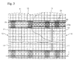
FIG. 3 shows a part of a wall of the liquefied gas storage tank of FIG. 2, viewed from the position of arrow III in FIG. 2, and having the unit-wall structures stacked to with respect to each other in accordance with one embodiment of the present disclosure;
FIG. 4 is a perspective view of a unit-wall structure for the liquefied gas storage tank in accordance with one embodiment of the present disclosure; and
FIG. 5 is a side view of a height-adjustable positioning block in accordance with one embodiment.
DETAILED DESCRIPTION
Embodiments of the present disclosure will now be described in detail with reference to the accompanying drawings in FIGS. 2-5.
Referring to FIGS. 2 to 4, a liquefied gas storage tank on land in accordance with one embodiment is constructed by stacking a plurality of unit-wall structures 10 in an approximately cylindrical arrangement on a foundation or base 1. Each of the unit-wall structures 10 is made of concrete and has a parallelepiped shape wherein iron rods 11 are arranged lengthwise and breadthwise.
Since the storage tank has a cylindrical wall formed by stacking the unit-wall structures 10, each of the unit-wall structures 10 may be rounded to have a substantially arc shape as shown in FIG. 4. Here, since the storage tank has a much greater radius than the width of each of the unit-wall structures, the unit-wall structure will be described as having a substantially parallelepiped shape hereinafter.
Each of the unit-wall structures 10 has grooves 13 on upper, lower, left and right surfaces thereof so that a positioning block 21 is disposed on each of the grooves 13 to stack the unit-wall structures 10 in place. The positioning blocks 21 allow each of the unit-wall structures 10 to be accurately located in place when the unit-wall structures 10 are stacked. Similar to the positioning block 21, a block (not shown) may be interposed between the unit-wall structures 10 adjacent to each other in a lateral direction to align the adjacent unit-wall structures 10 with each other.
In each of the unit-wall structures 10, two sets of iron rods 10 are arranged lengthwise and breadthwise, such that one set of iron rods 10 is assigned to the front side (left side in FIG. 2) of the unit-wall structure 10 and the other set is assigned to the rear side thereof. Distal ends of the iron rods 11 protrude from upper, lower, left and right surfaces of the unit-wall structure 10.
Thus, the distal ends of the iron cores 11 may protrude from the upper, lower, left and right surfaces of the unit-wall structure 10 to be arranged in two rows, as shown in FIG. 4. In one embodiment, referring to FIGS. 2 and 4, the iron rods 11 protruding from the upper and lower surfaces of the unit-wall structure 10 in the vertical direction may be further biased toward the front side or the rear side of the unit-wall structure 10 than the grooves 13 on which the positioning blocks 21 will be disposed.
The protruded iron rods of the adjacent unit-wall structures may be connected to one another by iron rod connecting plates 23, so that the adjacent unit-wall structures are secured to each other. To connect the iron rods to each other through the iron rod connecting plates 23, for example, welding may be performed. Alternatively, bolts, clamps or other fasteners may be used.
When stacking the pre-produced unit-wall structures at field sites, it is important to consider continuity (that is, prevention of stress concentration) and constructability (that is, method of connecting the iron rods of the respective unit-wall structures to each other) of the iron rods. In the embodiment, the exposed iron rods of the adjacent unit-wall structures are connected to each other by the iron rod connecting plates 23, thereby satisfying both continuity and constructability of the iron rods.
The iron rod connecting plate 23 may be configured to allow one iron plate to connect the iron rods 11 which are exposed from the unit-wall structures 10 adjacent to each other in the vertical or lateral direction. Alternatively, the iron rod connecting plate 23 may be configured to allow a pair of iron plates, which are attached to each other and joined to other adjacent iron plates by line-welding, to connect only the iron rods 11 to each other at one side of the unit-wall structure.
In one embodiment, when the unit-wall structures 10 are stacked with the positioning block 21 interposed therebetween, the height of the positioning block 21 is selected so as to prevent the distal ends of the iron rods 11 protruding from the surfaces of the unit-wall structures 10 adjacent to each other in the vertical direction from interfering with each other. For example, the height of the positioning block 21 is designed such that the ends of iron rods 11 of adjacent unit-wall structures 10 are spaced from each other by a small, selected distance.
In order to correct any possible error at a construction site, the positioning block 21 may be divided into upper and lower blocks 21 a and 21 b with a slanted plane provided as a border therebetween, as shown in FIG. 5 in one alternative embodiment. If the unit-wall structures 10 are stacked in actual construction to a height less than a design height, the upper block 21 a is slightly moved downward (to the left side in FIG. 5) along the slanted plane as indicated by a solid line in FIG. 5 to lower the height of the positioning block 21. On the contrary, if the unit-wall structures 10 are stacked in actual construction to a height greater than the design height, the upper block 21 a is slightly moved upward (to the right side in FIG. 5) along the slanted plane as indicated by a dotted line in FIG. 5 to increase the height of the positioning block 21.
In an embodiment that includes a multiple piece positioning block 21, other components may be included to control the movement of each block piece with respect to other block pieces. For example, fasteners, shims, or other structure, mechanism, or feature, can be incorporated to adjust and control exact height, position and movement of the block pieces of the embodiment of FIG. 5.
After the adjacent unit-wall structures 10 are connected to each other by the iron rod connecting plates 23, concrete may be cast into a space between the unit-wall structures 10 to prevent the iron rods 11 and the iron rod connecting plates 11 from being exposed. With this configuration, all of the unit-wall structures can be connected to each other to construct the cylindrical wall of the storage tank.
The plate 23 can be a size that, based on the height of block 21, will connect to the free ends of respective rods 11 from two different structures 10. The block 21 is a single solid block having predetermined height that is selected based on the length of the rods 11, the depths of groove 13 and the other factors to place the unit structures 10 the correct, exact distance from each other.
Blocks 21 of different heights can be obtained at a much lower cast than other changes in the wall, therefore if the groove is made a different depth or the length that rods 11 extend from the unit structure 10 varies, blocks 21 of a different height can be obtained to still continue with the proper spacing of between the unit structures 10.
As shown in FIG. 1, a front side connecting plate 25 and a rear side connecting plate 27 may be provided to front and rear sides of the adjacent unit-wall structures 10 to connect the adjacent front sides to each other and connect the adjacent rear sides to each other, respectively, while serving as moulds for casting concrete.
In order to facilitate installation of the front and rear side connecting plates 25, 27 by welding, the upper, lower, left and right surfaces of the unit-wall structures 10 may be surrounded by a metal frame 15.
In one aspect, the iron rod connecting plate 23 may be formed with a plurality of through-holes 23 a through which the concrete can be easily cast into the iron rod connecting plate 23.
The iron rod connecting plate 23, the front side connecting plate 25, and the rear side connecting plate 27 can be used not only for connecting the unit-wall structures adjacent to each other in the vertical direction but also for connecting the unit-wall structures adjacent to each other in the lateral direction.
As such, according to one embodiment, all of the unit-wall structures 10 may be integrated to construct the integral cylindrical wall of the storage tank while ensuring sufficient strength by casting the concrete in the space between the adjacent unit-wall structures 10 while connecting the adjacent unit-wall structures to one another in the vertical and lateral directions using the iron rod connecting plate 23, the front side connecting plate 25, and the rear side connecting plate 27.
In one aspect, as shown in FIG. 4, a sealing layer 19, that is, a gas sealing wall acting as a gas barrier, may be attached to the rear side of the unit-wall structure 10, that is, an interior surface of the storage tank, to shield against gas leakage. By producing the unit-wall structures with the sealing layers 19 attached thereto, the wall of the storage tank can be advantageously constructed by stacking the unit-wall structures 10 in a cylindrical arrangement and connecting them to one another without separately stacking the sealing layers after constructing the wall of the storage tank. In some embodiments, the sealing layer 19 of at least some of the unit-wall structures 10 may extend beyond the boundaries of the interior surface thereof to overlap with the sealing layer 19 of adjacent unit-wall structures 10.
Next, a method of constructing a liquefied gas storage tank on land in accordance with one embodiment will be described with reference to FIGS. 2 to 4.
In this embodiment, the method may include producing unit-wall structures 10 using concrete, stacking the unit-wall structures 10 in a cylindrical arrangement, and connecting the adjacent unit-wall structures 10 to one another. The unit-wall structures 10 can each be formed in a generally parallelepiped shape with a curvature, which upon assembly of the unit-wall structures 10 forms a substantially cylindrical storage tank. The radius of curvature of unit structures 10 will determine the overall diameter of the completed tank.
As described above, each of the unit-wall structures 10 may be produced by casting concrete into a mould with iron rods 11 arranged lengthwise and breadthwise. Here, the unit-wall structure 10 may have grooves 13 on upper, lower, left and right surfaces thereof, and may be provided with a sealing layer 19 at one side thereof, that is, an inner surface of the completed storage tank.
When stacking the unit-wall structures 10 in the cylindrical arrangement, one or more positioning blocks 21 are disposed on the grooves 13, which are formed on the upper and lower surfaces of the unit-wall structure 10, to be interposed between the unit-wall structures 10 adjacent to each other in the vertical direction. With this configuration, positioning of the unit-wall structures 10 may be securely and conveniently achieved.
Then, exposed iron rods 11 of each unit-wall structure 10 are connected to those of other unit-wall structures 10 adjacent thereto in the vertical and lateral directions through iron rod connecting plates 23. In one aspect, the iron rods 11 and the iron rod connecting plates 23 may be integrally joined by welding or the like.
Further, adjacent front sides of the stacked unit-wall structures 10 are connected to each other by front side connecting plates 25, and adjacent rear sides of the stacked unit-wall structures 10 are connected to each other by rear side connecting plates 27.
Then, concrete is cast into a space between the unit-wall structures 10 adjacent to one another in the vertical and lateral directions, so that the stacked unit-wall structures 10 are completely connected and integrated.
On the other hand, foundation work may be performed on the ground to form a flat foundation before stacking the unit-wall structures 10 in the cylindrical arrangement. In one aspect, after stacking and connecting the unit-wall structures 10 to one another, operation of installing a cover is performed to complete a tank body of the storage tank, and a heat insulating wall and a sealing wall are disposed inside the tank body, thereby completing the liquefied gas storage tank.
In embodiments that include the sealing layer 19, when the sealing layer 19 is attached to the unit-wall structure 10 as shown in FIG. 4, the sealing wall may be formed while connecting the stacked unit-wall structures 10 without a separate operation of installing the sealing wall after completing the tank body.
In one embodiment, the pre-produced unit-wall structures made of concrete are stacked and concrete is then cast into spaces between the unit-wall structures at a construction site, thereby constructing the wall of the storage tank. As a result, the respective unit-wall structures can be more strongly integrated with one another using concrete as a binder of the unit-wall structures while reducing time consumed for construction of the storage tank.
A method according to embodiments of the present disclosure enables rapid and easy construction of a cylindrical wall of a liquefied gas storage tank by stacking a plurality of pre-produced unit-wall structures to be stacked or superposed with respect to one another, enabling a considerable reduction in time for construction of the liquefied gas storage tank on land, and reducing construction costs.
The various embodiments described above can be combined to provide further embodiments. All of the U.S. patents, U.S. patent application publications, U.S. patent applications, foreign patents, foreign patent applications and non-patent publications referred to in this specification and/or listed in the Application Data Sheet are incorporated herein by reference, in their entirety. Aspects of the embodiments can be modified, if necessary, to employ concepts of the various patents, applications and publications to provide yet further embodiments.
These and other changes can be made to the embodiments in light of the above-detailed description. In general, in the following claims, the terms used should not be construed to limit the claims to the specific embodiments disclosed in the specification and the claims, but should be construed to include all possible embodiments along with the full scope of equivalents to which such claims are entitled. Accordingly, the claims are not limited by the disclosure.

Claims (10)

The invention claimed is:
1. A method of constructing a liquefied gas storage tank on land, comprising:
stacking a plurality of unit-wall structures made of concrete and each having a front set and a rear set of iron rods arranged lengthwise and breadthwise therein, in a cylindrical arrangement, each of the unit-wall structures having respective grooves on upper and lower surfaces thereof, the stacking the plurality of unit-wall structures including
interposing a positioning block between adjacent unit-wall structures within a corresponding set of the grooves on the adjacent unit-wall structures to ensure that the unit-wall structures are located in a desired position with respect to each other when the unit-wall structures are stacked, the positioning block located between protruded ends of the lengthwise iron rods of the front set and the rear set of iron rods of the adjacent unit-wall structures with a front side of the positioning block spaced inwardly from the protruded ends of the lengthwise iron rods of the front set of iron rods and a rear side of the positioning block spaced inwardly from the protruded ends of the lengthwise iron rods of the rear set of iron rods; and
connecting the unit-wall structures that are adjacent to each other in longitudinal and lateral directions with respect to each other to form a wall of the storage tank.
2. The method according to claim 1 wherein each of the unit-wall structures further has respective grooves on left and right surfaces thereof.
3. The method according to claim 1 wherein the lengthwise iron rods protrude from opposing terminal longitudinal surfaces of each unit-wall structure, the breadthwise iron rods protrude from opposing terminal lateral surfaces of each unit-wall structure, and the connecting the unit-wall structures includes connecting the protruded iron rods of each of the unit-wall structures to the protruded iron rods of other unit-wall structures adjacent thereto in the longitudinal and lateral directions.
4. The method according to claim 3 wherein the iron rods are connected to each other through an iron rod plate having a plurality of through-holes.
5. The method according to claim 3 wherein the connecting the unit-wall structures includes connecting front sides of the unit-wall structures to each other and connecting rear sides of the unit-wall structures to each other, after connecting the iron rods to the iron rods of adjacent unit-wall structures.
6. The method according to claim 5 wherein the front sides of the unit-wall structures are connected to each other through a front side connecting plate and the rear sides of the unit-wall structures are connected to each other through a rear side connecting plate.
7. The method according to claim 3, further comprising:
casting concrete into a space between the unit-wall structures to integrate the unit-wall structures with each other after connecting the iron rods to the iron rods of adjacent unit-wall structures.
8. The method according to claim 1 wherein each of the unit-wall structures is provided at one side thereof with a sealing layer, and the connecting the unit-wall structures includes connecting the sealing layers of the respective unit-wall structures to each other.
9. The method according to claim 1, further comprising:
performing foundation work to form a foundation before stacking the unit-wall structures; and
placing a cover to complete a tank body of the storage tank after connecting the unit-wall structures.
10. A method of constructing a storage tank, the method comprising:
stacking a plurality of unit-wall structures each having a front set and a rear set of connecting rods arranged lengthwise and breadthwise therein and each having respective grooves on an upper mating surface and a lower surface thereof;
interposing a positioning block between adjacent unit-wall structures within a corresponding set of the grooves of the adjacent unit-wall structures while stacking the adjacent unit-wall structures with a front side of the positioning block spaced inwardly from protruded ends of the lengthwise connecting rods of the front set of connecting rods of the adjacent unit-wall structures and a rear side of the positioning block spaced inwardly from protruded ends of the lengthwise connecting rods of the rear set of connecting rods of the adjacent unit-wall structures; and
connecting the unit-wall structures that are adjacent to each other in longitudinal and lateral directions with respect to each other to form a wall of the storage tank.
US12/627,969 2009-11-05 2009-11-30 Method of constructing liquefied gas storage tank on land Expired - Fee Related US8627636B2 (en)

Applications Claiming Priority (2)

Application Number Priority Date Filing Date Title
KR1020090106530A KR100964824B1 (en) 2009-11-05 2009-11-05 Method for building a liquefied gas storage tank
KR10-2009-0106530 2009-11-05

Publications (2)

Publication Number Publication Date
US20110099940A1 US20110099940A1 (en) 2011-05-05
US8627636B2 true US8627636B2 (en) 2014-01-14

Family

ID=42370255

Family Applications (1)

Application Number Title Priority Date Filing Date
US12/627,969 Expired - Fee Related US8627636B2 (en) 2009-11-05 2009-11-30 Method of constructing liquefied gas storage tank on land

Country Status (5)

Country Link
US (1) US8627636B2 (en)
EP (1) EP2320122B1 (en)
JP (1) JP5049331B2 (en)
KR (1) KR100964824B1 (en)
CN (1) CN102051992B (en)

Families Citing this family (11)

* Cited by examiner, † Cited by third party
Publication number Priority date Publication date Assignee Title
EP2547948B1 (en) * 2010-03-17 2014-01-29 Air Products and Chemicals, Inc. Cryogenic storage tank
JP5998616B2 (en) * 2012-04-26 2016-09-28 株式会社Ihi Independent liner unit and tank construction method
CN103741980B (en) * 2012-10-17 2016-04-20 重庆宇冠数控科技有限公司 The design and manufaction of rectangle or rectangle ultra-large type LNG storage tank
CN103758387B (en) * 2014-02-19 2016-02-10 中国海洋石油总公司 The mounting method of liquefied natural gas (LNG) tank wallboard
JP5837118B2 (en) * 2014-03-14 2015-12-24 鹿島建設株式会社 Construction method of tank and breakwater
JP6421433B2 (en) * 2014-04-04 2018-11-14 株式会社Ihi Precast block connection method and prestress tank using the same
US9284114B2 (en) * 2014-08-18 2016-03-15 Chevron U.S.A. Inc. Method of construction of prestressed concrete panel wall liquid storage tank and tank so constructed
JP5791777B1 (en) 2014-11-06 2015-10-07 鹿島建設株式会社 Joining structure and joining method
FR3052229B1 (en) * 2016-06-01 2018-07-06 Gaztransport Et Technigaz SEALED AND THERMALLY INSULATING TANK INTEGRATED IN A POLYEDRIAL CARRIER STRUCTURE
FR3102531B1 (en) * 2019-10-24 2021-11-12 Ifp Energies Now Energy storage tank in the form of pressurized gas, made of ultra-high performance fiber-reinforced concrete
KR102679431B1 (en) * 2023-09-11 2024-06-27 주식회사 한국가스기술공사 Arrangement and Installation Method of Thermal Corner Protection System Wall Plate in Cryogenic Storage Tank

Citations (17)

* Cited by examiner, † Cited by third party
Publication number Priority date Publication date Assignee Title
US1050130A (en) * 1912-05-03 1913-01-14 George C Harvey Concrete structure.
GB718606A (en) 1951-10-08 1954-11-17 Wilfrid Cracroft Ash An improved storage tank for liquids and a method of constructing same
US3300943A (en) * 1964-04-29 1967-01-31 Albert C Racine Building system
US4006570A (en) * 1974-04-01 1977-02-08 Stolz Owen M Wall structure and manufacturing method therefor
US4180951A (en) * 1977-07-05 1980-01-01 Gesellschaft zur Forderung der Forschung an der Eidg. Hochschule Techn. Masonry wall, method for its production, and its use
JPS56120900A (en) 1980-02-25 1981-09-22 Toyo Kanetsu Kk Double shell low temperature liquid storage tank
GB2124743A (en) 1982-06-05 1984-02-22 Kawasaki Heavy Ind Ltd Low temperature storage tank
FR2539792A1 (en) 1983-01-26 1984-07-27 Matiere Marcel Method for constructing watertight structures, such as reservoirs (tanks)
US5038540A (en) * 1981-11-20 1991-08-13 Krautz Alfons O Sectional smokestack
FR2658228A1 (en) 1990-02-14 1991-08-16 Lachize Claudius Method for constructing reinforced concrete reservoirs, prefabricated elements for implementing the said method and machine for producing the said elements
CN2270083Y (en) 1996-05-03 1997-12-10 洪文章 Quick removing and assembling type fireproof movable partition wall
JP2000336969A (en) 1999-05-25 2000-12-05 Kankoku Fiberglass:Kk Side wall structure of lng storage tank and construction method therefor
US6401417B1 (en) * 1997-08-22 2002-06-11 Leblang Dennis Concrete form structure
JP2004106884A (en) 2002-09-18 2004-04-08 Shimizu Corp Construction method for tank sidewall
KR100430862B1 (en) 2003-09-16 2004-05-10 주식회사 한텍 Method for constructing of liquefied gas storage tank
US7555872B1 (en) * 2005-01-04 2009-07-07 Jeffrey Beach Spacer for aligning concrete blocks
US20110099930A1 (en) 2009-11-05 2011-05-05 Korea Gas Corporation Wall Structure for Building a Liquefied Gas Storage Tank

Family Cites Families (12)

* Cited by examiner, † Cited by third party
Publication number Priority date Publication date Assignee Title
GB191517719A (en) * 1915-12-18 1916-12-18 Evan Owen Williams Improvements in the Construction of Reinforced Concrete Tanks, Tuns, Bins, Silos, Vessels and the like.
US1452583A (en) * 1921-05-09 1923-04-24 Walter J Williams Interlocking fire brick for arches
US2501951A (en) * 1945-07-24 1950-03-28 Lintz Mark Construction of tanks, silos, and like vessels
FR1006081A (en) * 1947-11-10 1952-04-18 Improvements made to removable constructions such as chimneys, silos, etc.
JPS5916625B2 (en) * 1976-09-30 1984-04-17 石川島建材工業株式会社 How to build an underground tank
JPS54141511U (en) * 1978-03-25 1979-10-01
JPS60175668A (en) * 1984-02-21 1985-09-09 川崎重工業株式会社 Construction of cylindrical tank
JP3111282B2 (en) * 1990-08-31 2000-11-20 株式会社石井鐵工所 Prefabricated concrete storage tank
JP3407026B2 (en) * 1993-06-11 2003-05-19 株式会社竹中工務店 Segment for shield method for underground tank construction and underground tank for storage of LNG etc.
IL141467A0 (en) * 2001-02-15 2002-03-10 Industrial walls
US7162844B2 (en) * 2003-01-09 2007-01-16 Chicago Bridge & Iron Company Use of partial precast panels for construction of concrete walls and shells
KR100589527B1 (en) * 2003-01-25 2006-06-15 유천만 protection wall for concrete pre cast purification tank

Patent Citations (17)

* Cited by examiner, † Cited by third party
Publication number Priority date Publication date Assignee Title
US1050130A (en) * 1912-05-03 1913-01-14 George C Harvey Concrete structure.
GB718606A (en) 1951-10-08 1954-11-17 Wilfrid Cracroft Ash An improved storage tank for liquids and a method of constructing same
US3300943A (en) * 1964-04-29 1967-01-31 Albert C Racine Building system
US4006570A (en) * 1974-04-01 1977-02-08 Stolz Owen M Wall structure and manufacturing method therefor
US4180951A (en) * 1977-07-05 1980-01-01 Gesellschaft zur Forderung der Forschung an der Eidg. Hochschule Techn. Masonry wall, method for its production, and its use
JPS56120900A (en) 1980-02-25 1981-09-22 Toyo Kanetsu Kk Double shell low temperature liquid storage tank
US5038540A (en) * 1981-11-20 1991-08-13 Krautz Alfons O Sectional smokestack
GB2124743A (en) 1982-06-05 1984-02-22 Kawasaki Heavy Ind Ltd Low temperature storage tank
FR2539792A1 (en) 1983-01-26 1984-07-27 Matiere Marcel Method for constructing watertight structures, such as reservoirs (tanks)
FR2658228A1 (en) 1990-02-14 1991-08-16 Lachize Claudius Method for constructing reinforced concrete reservoirs, prefabricated elements for implementing the said method and machine for producing the said elements
CN2270083Y (en) 1996-05-03 1997-12-10 洪文章 Quick removing and assembling type fireproof movable partition wall
US6401417B1 (en) * 1997-08-22 2002-06-11 Leblang Dennis Concrete form structure
JP2000336969A (en) 1999-05-25 2000-12-05 Kankoku Fiberglass:Kk Side wall structure of lng storage tank and construction method therefor
JP2004106884A (en) 2002-09-18 2004-04-08 Shimizu Corp Construction method for tank sidewall
KR100430862B1 (en) 2003-09-16 2004-05-10 주식회사 한텍 Method for constructing of liquefied gas storage tank
US7555872B1 (en) * 2005-01-04 2009-07-07 Jeffrey Beach Spacer for aligning concrete blocks
US20110099930A1 (en) 2009-11-05 2011-05-05 Korea Gas Corporation Wall Structure for Building a Liquefied Gas Storage Tank

Also Published As

Publication number Publication date
CN102051992A (en) 2011-05-11
EP2320122A3 (en) 2017-05-10
CN102051992B (en) 2013-11-13
EP2320122A2 (en) 2011-05-11
US20110099940A1 (en) 2011-05-05
JP5049331B2 (en) 2012-10-17
EP2320122B1 (en) 2020-09-09
KR100964824B1 (en) 2010-06-23
JP2011099550A (en) 2011-05-19

Similar Documents

Publication Publication Date Title
US8627636B2 (en) Method of constructing liquefied gas storage tank on land
US8656673B2 (en) Wall structure for building a liquefied gas storage tank
US9664338B2 (en) Method for constructing low-temperature tank and low-temperature tank
KR102226313B1 (en) Uncoupling of the corrugations of an impervious barrier
US20140299038A1 (en) Cargo tank for extremely low temperature substance carrier
WO2013015296A1 (en) Lng tank loaded on board lng ship, and method for producing same
CN102369386A (en) Cryogenic liquid storage tank
JP2007527490A (en) Semi-membrane tank support assembly and system
KR101455637B1 (en) Insualtion structure of storage tank for lng
KR101884033B1 (en) Cargo Tank for LNG Carrier
CN207812181U (en) Track, track girder and its crane beam
KR101141972B1 (en) Method for constructing side wall of storage tank for liquefied natural gas(lng) using rebar panel
JP5672787B2 (en) Construction method of cylindrical tank
CN106001955B (en) A kind of method of construction of self-elevating platform up-down system gear-box
CN105149881B (en) A kind of group of conjoined storage tank is to method
KR102095422B1 (en) Metal membrane for lng storage tank
JP2017089163A (en) Building method of double-shell low-temperature storage tank
KR101964638B1 (en) Onshore membrane tank including embedded plate
KR20150069749A (en) Membrane of lng cargo tank
JP2016020597A (en) Construction method of tank and dike
KR20150072011A (en) Membrane of lng cargo tank
KR101178258B1 (en) Membrane for Minimizing Remaning L.N.G
KR101577743B1 (en) Lng storage tank and construction method for lng storage tank
KR101437745B1 (en) Aboveground type liquid storage tank and method for constructing there of
JP2014037167A (en) Lng tank loaded on lng carrier, and method of manufacturing the same

Legal Events

Date Code Title Description
AS Assignment

Owner name: KOREA GAS CORPORATION, KOREA, DEMOCRATIC PEOPLE'S

Free format text: ASSIGNMENT OF ASSIGNORS INTEREST;ASSIGNORS:YANG, YOUNG MYUNG;YOON, IHN SOO;SEO, HEUNG SEOK;AND OTHERS;REEL/FRAME:024326/0625

Effective date: 20091204

STCF Information on status: patent grant

Free format text: PATENTED CASE

FPAY Fee payment

Year of fee payment: 4

FEPP Fee payment procedure

Free format text: MAINTENANCE FEE REMINDER MAILED (ORIGINAL EVENT CODE: REM.); ENTITY STATUS OF PATENT OWNER: LARGE ENTITY

LAPS Lapse for failure to pay maintenance fees

Free format text: PATENT EXPIRED FOR FAILURE TO PAY MAINTENANCE FEES (ORIGINAL EVENT CODE: EXP.); ENTITY STATUS OF PATENT OWNER: LARGE ENTITY

STCH Information on status: patent discontinuation

Free format text: PATENT EXPIRED DUE TO NONPAYMENT OF MAINTENANCE FEES UNDER 37 CFR 1.362

FP Lapsed due to failure to pay maintenance fee

Effective date: 20220114