JP4986098B2 - Positive electrode for non-aqueous lithium secondary battery and non-aqueous lithium secondary battery using the same - Google Patents
Positive electrode for non-aqueous lithium secondary battery and non-aqueous lithium secondary battery using the same Download PDFInfo
- Publication number
- JP4986098B2 JP4986098B2 JP2001073799A JP2001073799A JP4986098B2 JP 4986098 B2 JP4986098 B2 JP 4986098B2 JP 2001073799 A JP2001073799 A JP 2001073799A JP 2001073799 A JP2001073799 A JP 2001073799A JP 4986098 B2 JP4986098 B2 JP 4986098B2
- Authority
- JP
- Japan
- Prior art keywords
- positive electrode
- active material
- secondary battery
- electrode active
- lithium secondary
- Prior art date
- Legal status (The legal status is an assumption and is not a legal conclusion. Google has not performed a legal analysis and makes no representation as to the accuracy of the status listed.)
- Expired - Fee Related
Links
Images


Classifications
-
- Y—GENERAL TAGGING OF NEW TECHNOLOGICAL DEVELOPMENTS; GENERAL TAGGING OF CROSS-SECTIONAL TECHNOLOGIES SPANNING OVER SEVERAL SECTIONS OF THE IPC; TECHNICAL SUBJECTS COVERED BY FORMER USPC CROSS-REFERENCE ART COLLECTIONS [XRACs] AND DIGESTS
- Y02—TECHNOLOGIES OR APPLICATIONS FOR MITIGATION OR ADAPTATION AGAINST CLIMATE CHANGE
- Y02E—REDUCTION OF GREENHOUSE GAS [GHG] EMISSIONS, RELATED TO ENERGY GENERATION, TRANSMISSION OR DISTRIBUTION
- Y02E60/00—Enabling technologies; Technologies with a potential or indirect contribution to GHG emissions mitigation
- Y02E60/10—Energy storage using batteries
Description
【0001】
【発明の属する技術分野】
本発明は、非水系リチウム二次電池の正極活物質に関し、正極活物質を電極上に塗布−プレスしたときの結晶方位を制御することにより、正極活物質の抵抗を低減し、ひいては電池の内部抵抗を低減し、非水系リチウム二次電池として大電流放電を可能にすることに関するものである。
【0002】
【従来の技術】
リチウム二次電池はニッケルカドミウム電池、ニッケル水素電池に比べて、エネルギ−密度が高く、携帯端末等の分野で急速に普及している。またEVや電力貯蔵の分野でも期待されている。リチウム二次電池は正極、負極およびセパレータを容器内に配置し、有機溶媒による非水電解液を充たして構成されている。正極はアルミニウム箔等の集電体に正極活物質を塗布し加圧成形したものである。正極活物質としてはα−NaFeO2構造を有するコバルト酸リチウム(LiCoO2)、ニッケル酸リチウム(LiNiO2)、スピネル型構造を有するマンガン酸リチウム(LiMn2O4)などに代表されるようなリチウムと遷移金属の複合酸化物(以下、リチウム遷移金属酸化物と言う。)の粉体が主として用いられ、例えば特開平8−17471号公報にはその製法が詳しく開示されている。特にα−NaFeO2構造を有するコバルト酸リチウム(LiCoO2)やニッケル酸リチウム(LiNiO2)はスピネル型構造を有するマンガン酸リチウム(LiMn2O4)に比べて放電容量が大きく携帯端末用のLiイオン電池の正極活物質として実用化されている。これら正極活物質の合成は一般にリチウム化合物(LiOH、 Li2CO3等)粉末と遷移金属化合物(CoO、 NiO等)粉末を混合し、焼成、粉砕してリチウム遷移金属酸化物とする方法が広く採用されている。正極活物質を集電体に塗布する際には、正極活物質に重量比で数%〜数十%程度の炭素粉を混ぜ、さらにPVDF(ポリフッ化ビリニデン)、PTFE(ポリテトラフルオロエチレン)等の結着材と混練してペースト状にして集電体箔上に厚み20μm〜100μmに塗布、乾燥、プレス工程を経て正電極が作られている。
【0003】
これら正極活物質は、電気伝導率が10-1〜10-6S/cm2で一般の導体と比べ低く、そのまま電極に塗布すると、内部抵抗の高い電池となり、大電流放電を要求される状況では出力が取れない。そこで、アルミニウム集電体と正極活物質間もしくは活物質相互間の電気伝導性を更に高めるように、正極活物質よりも電気伝導率の高い炭素粉等の導電助材を添加して正極が構成される。また、電解液との接触面積を増やすために粉砕して粒径を細かくし比表面積を大きくした正極活物質を電極表面に塗布するなどの試みがなされている。
【0004】
【発明が解決しようとする課題】
以上述べた従来技術において、正極活物質よりも電気伝導率の高い炭素粉等の導電助材を添加したり、電解液との接触面積を増やすために正極活物質を粉砕して粒径を細かする方法で大電流放電時の出力はある程度改善されているものの、まだまだ要求には不十分なレベルである。このような大電流を安定して放電するためには、正極活物質内のLiイオンの拡散速度を向上させる必要がある。一般に正極活物質として良く用いられているLiCoO2やLiNiO2はα-NaFeO2に代表される層状岩塩構造を有している。この構造は、例えばリチウムイオン二次電池(日刊工業新聞社)に記載されているようにリチウムと遷移金属がそれぞれ(111)酸素層間に並んだ単独層を形成し、これが交互に積層することによって六方晶の超格子を構成している(六方晶層状岩塩構造)。この場合のLiイオンの拡散パスは図1に示すように六方晶層状岩塩構造の(003)面と平行な方向となる。つまり、(003)面に垂直な方向からはLiイオンは正極活物質内に出入りすることは出来ない。一般に用いられている合成方法において、すなわちリチウム化合物(LiOH、 Li2CO3等)粉末と遷移金属化合物(MnO2 、 CoO、 NiO等)粉末を混合し、これを焼成−粉砕してα-NaFeO2構造のLiCoO2やLiNiO2等の正極活物質を得る場合、図2に示すように焼成後の粉砕時に(003)面と平行にへき開しやすいため扁平状の粒子が得られる。これをAl箔等の集電体に塗布、プレスして得られた正極では、図3に示すように正極粒子の(003)面が電極面と平行に配向しやすくなる。充放電におけるLiイオンは電極面と垂直方向に移動するので、正極活物質へ出入りするためには、(003)面に平行な方向から回りこむ必要がある。このため、上記のような(003)面が電極面と平行に配向した場合、急速な充放電時にはLiイオンは正極粒子内へ出入りできにくくなり、正極活物質表面のLiイオン濃度が上昇してしまう。電極電位は正極活物質内のLiイオン濃度に影響されるため電極電位が低下してしまい、結果として電池としての出力が取れなくなっている。
【0005】
この配向を制御する方法も検討されている。例えば、特開2001−23639号公報には、焼成前の原料であるCo3O4の粒径と焼成温度を制御し、得られたLiCoO2のX線回折の強度比をI(003)/(110)≦5.6かつI(105)/(113)≧0.9及びI(110)/(113)≦1.35とすることで充電高温下でも安全で高いエネルギー密度を有する非水電解液二次電池を提供できるとしている。
しかし、焼成時にLiCoO2の配向を制御しても、電極へ塗布する場合には平均粒子径を10〜20μm程度にまで粉砕する必要があり、この時に前記の様に(003)面と平行にへき開しやすいため扁平状の粒子となりやすい。これをAl箔等の集電体に塗布、プレスして得られた正極では、やはり正極粒子の(003)面が電極面と平行に配向しやすくなる。このため特開2001−23639号公報に記載の手法でも大電流放電時には電池の出力が取れなくなる。
【0006】
本発明の目的は、正極活物質が電極上に塗布−プレス(塗布、乾燥、プレス工程)されたときの、正極活物質の結晶方位を制御することで、放電時における正極活物質内のLiイオンの拡散速度を上げ、電池の内部抵抗を低減し、大電流放電した場合でも電圧降下の少ない出力特性に優れた正極および非水系リチウム二次電池を提供することである。
【0007】
【課題を解決するための手段】
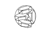
先ず、本発明の正極の正極活物質は、図4に示すようなα−NaFeO2構造をもつ一次粒子を球状に凝集させた二次粒子であることは重要な特徴の一つである。その上で本発明では、それを電極上に塗布−プレス(1.5ton/cm2程度の圧力でプレス)した平面から得られる正極活物質からのX線回折の(110)/(003)のピ−ク強度比が0.10以上としたことを特徴としている。
即ち、請求項1の発明は、α-NaFeO2構造を有するリチウムと遷移金属の複合酸化物粉末を正極活物質とした正極において、前記正極活物質は一次粒子を球状に凝集させた二次粒子となし、当該正極活物質を電極上に塗布−プレスした時のX線回折による(110)面の回折ピーク強度と、(003)面の回折ピーク強度との比である(110)/(003)のピ−ク強度比が0.10以上であることを特徴とする非水系リチウム二次電池用正極である。
【0008】
請求項2の発明は、上記正極において、前記(110)/(003)のピ−ク強度比が0.10以上、0.18以下である非水系リチウム二次電池用正極である。
【0009】
請求項3の発明は、前記正極活物質は、1〜30μmの球状に凝集させた二次粒子を900℃以上、1100℃未満で焼成したものである非水系リチウム二次電池用正極である。
【0010】
本発明の非水系リチウム二次電池は、集電体に正極活物質を塗布−プレスしてなる正極と、負極およびセパレータを容器内に配置し、有機溶媒による非水電解液を満たして構成される非水系リチウム二次電池であって、請求項1〜3の何れかに記載の正極を用いて構成されたことを特徴とする非水系リチウム二次電池である。
また、本発明の非水系リチウム二次電池用正極の製造方法は、集電体に正極活物質としてα-NaFeO 2 構造を有するリチウムと遷移金属の複合酸化物粉末を塗布−プレスしてなる非水系リチウム二次電池用正極の製造方法であって、原料の遷移金属の化合物とリチウム化合物とを混合する工程と、前記工程によって得られた粉末を焼成してα-NaFeO 2 構造を有するリチウムと遷移金属の複合酸化物粉末を得る工程と、前記複合酸化物粉末を粉砕し、スラリーとなす工程と、前記スラリーをスプレイドライヤで乾燥し、球状化した凝集体となす工程と、前記凝集体を900℃以上、1100℃未満の温度で焼成した後、解砕して正極活物質を得る工程と、前記正極活物質を集電体である電極上に塗布−プレスする工程とを有し、前記正極活物質を前記電極上に塗布−プレスした時のX線回折による(110)面の回折ピーク強度と、(003)面の回折ピーク強度との比である(110)/(003)のピ−ク強度比が0.10以上であることを特徴とする
これら本発明により合成された正極の正極活物質は、α−NaFeO2構造をもつ一次粒子を球状に凝集させた二次粒子であるため、図5に示したようにプレスしたときの粒子の(003)面が電極表面と平行になりにくく、充放電時における正極活物質内のLiイオンの拡散速度が向上しており、ひいては大電流放電に適した正極及びそれを用いた非水系リチウム二次電池を提供できる。
【0011】
【発明の実施の形態】
本発明におけるα−NaFeO2構造を有するリチウム遷移金属酸化物は非水系リチウム二次電池用正極活物質として有用なもので、それを正極として使用した二次電池の充放電特性が特に大きくなる。
本発明によって非水系リチウム二次電池用正極活物質は図6のフローチャートに従って製造される。まず工程1で原料として、焼成によって酸化物となる遷移金属、例えばコバルト、ニッケル、マンガン、の化合物(例えばCo3O4, CoO, Mn3O4, MnCO3)と、焼成によって酸化物となるリチウム化合物(例えばLi2CO3, LiOH)とを所定の割合で混合する。これらの粉末を工程2で水を加えてボールミル等で例えば50時間程度、粉砕混合しスラリ−とする。
工程3でスラリ−をスラリードライヤ等で乾燥させる。焼成は工程4であり、この焼成によって用いた原料が酸化物となって、α−NaFeO2構造を有するリチウム遷移金属酸化物となる。焼成は大気中や酸素中800℃〜1050℃で数時間から10時間行う。次に、焼成してα−NaFeO2構造を有するリチウム遷移金属酸化物となった粉末に、工程5で純水等を所定量加えて再びボ−ルミル等で平均粒径が1μm以下程度まで粉砕し、スラリ−とする。工程6でこのスラリ−にPVA溶液を固形分に換算して1wt%前後添加後、スプレイドライヤ−等で粒子径が1〜30μm程度となるように球状化を行う。次に工程7で焼成を大気中や酸素中800℃〜1050℃で数時間から10時間行う。焼成後、工程8で振動ミル等で解砕し、篩い分けを行う。
【0012】
本発明による正極活物質の特性評価は以下の手順で行った。まず、正極材、導電助材(炭素粉)、結着剤(8wt%PVdF/NMP)を重量比で85:10:5の割合でメノウ鉢にて混練しスラリ−状の合材とした。得られた合材を厚さ20μmの集電体(Al箔)上に約200μm厚に塗布した。塗布した合材は乾燥後、所定の寸法(巾10mm、長さはおよそ50mm)に切断し金型を用いて1.5ton/cm2の圧力でプレスした。得られた正極は十分に電解液(エチレンカ−ボネ−ト:ジメチルカ−ボネ−ト=1:2、電解質1M-LiPF6)に浸潤した後、セパレータ(25mm厚ポリエチレン)、金属リチウム対極、試験用電池とした。セルが電気化学的に平衡になるように数時間程度放置してから、充放電測定装置に接続し電池容量の測定を行った。
X線回折の測定は図7に示すような形で行った。Cu−Kα線を用いて、広角ゴニオメーターで調べた。走査方法は連続スキャンを用い、スキャン速度2度/分、サンプリング間隔0.006度とした。走査範囲は、2θ値で15〜100度とした。
【0013】
以下、本発明の効果を示す実施例について説明する。
(比較例1)
Li:Co=1:1となるように炭酸リチウムと酸化コバルトを秤量し、純水を添加後、ボ−ルミルで24時間混合しスラリ−とした。次に、スラリ−をスラリ−ドライヤ−(120℃)で乾燥後、アルミナルツボに充填し、電気炉中で950℃−10時間大気中にて焼成した。焼成した粉末を、ライカイ機にて粉砕し、45μmのフルイに通し粒径10μm程度の粉末を得た。
【0014】
(参考例1)Li:Co=1:1となるように炭酸リチウムと酸化コバルトを秤量し、純水を添加後、ボ−ルミルで24時間混合しスラリ−とした。次に、スラリ−をスラリ−ドライヤ−(120℃)で乾燥後、アルミナルツボに充填し、電気炉中で950℃−10時間大気中にて焼成した。焼成した粉末を、ライカイ機にて粉砕し、45μmのフルイに通し粒径10μm程度の粉末を得た。次に、再び焼成した粉末に純水添加後、ボ−ルミル等で粒子径が1μm程度まで粉砕しスラリ−とした。次にスラリ−にPVA溶液を固形分に換算して1wt%前後添加後、スプレイドライヤ−等で粒子径が1〜30μm程度となるように球状化を行う。次に焼成を大気中800℃で10時間行った。焼成後、振動ミル等で解砕し、45μmのメッシュにて篩い分けを行った。
【0015】
(実施例2)参考例1と同様な操作を行い、スプレイドライヤ−等で、粒子径が1〜30μm程度の球状凝集体を作成した後、焼成を大気中900℃で10時間行った。焼成後、振動ミル等で解砕し、45μmのメッシュにて篩い分けを行った。
(実施例3)参考例1と同様な操作を行い、スプレイドライヤ−等で、粒子径が1〜30μm程度の球状凝集体を作成した後、焼成を大気中1000℃で10時間行った。焼成後、振動ミル等で解砕し、45μmのメッシュにて篩い分けを行った。
(実施例4)参考例1と同様な操作を行い、スプレイドライヤ−等で、粒子径が1〜30μm程度の球状凝集体を作成した後、焼成を大気中1050℃で10時間行った。焼成後、振動ミル等で解砕し、45μmのメッシュにて篩い分けを行った。以上の評価結果を表1に示す。
【0016】
【表1】

比較例1は通常の方法で合成したLiCoO2である。図8(a)にこのときの粒形態のSEM写真を示す。偏平状の粒子が見られる。放電電流密度I=0.5mA/cm2での重量あたりの容量は155mAh/gと実用的な値であるが、放電電流密度I=6.0mA/cm2で得られる重量あたりの容量は130mAh/gとI=0.5mA/cm2のときの値に比べて84%程度である。このときの正極材が塗布−プレスされた電極面のX線回折を測定した結果を図9(a)に示す。これから(110)/(003)面の強度比をみると0.05程度である。このことにより、上記で説明したように、電極表面と平行に正極粒子の(003)面が配向していることが推測される。そのため、(003)の回折強度がそれと垂直な面である(110)面の回折に比べて大きく、結果として(110)/(003)の強度比が小さくなっている。
【0018】
一方、実施例で示す本発明の正極材は焼成−粉砕して得られた一次粒子を球状化して凝集体として再度焼成してあるため、電極に塗布してプレスしたあとも(003)が配向しにくく、(110)/(003)のピ−ク強度が比較例に比べて強くなっている。このことは、球状化後の焼成温度を高くするとより顕著に表れてくる。これは、凝集が焼成温度の高いほど強く球形状がくずれにくくなっているためと考えられる。図8(b)、図9(b)に本発明材として実施例4の粒形態のSEM写真とX線回折パタ−ンを示す。これらの粒形態及び回折強度比の結果は本発明の効果を支持するものである。そして、本実施例において(110)/(003)比が0.10以上でI=6.0mA/cm2での容量が142mAh/g以上と実用レベルの値を得られた。なお、1100℃以上での焼成は正極材の融点に近いため結晶構造が変化する危険があるので好ましくない。
【0019】
【発明の効果】
以上のように、本発明によれば、充放電時における正極活物質内のLiイオンの拡散速度が向上し、ひいては大電流放電に適した正極活物質とそれを用いた非水系リチウム二次電池を提供することが出来る。
【図面の簡単な説明】
【図1】α−NaFeO2構造の単位格子とLiイオンの拡散パスを示す模式図。
【図2】α−NaFeO2構造のへき開を示す説明図。
【図3】 LiCoO2活物質の電極上での配向の状況を示す概略図。
【図4】本発明の正極活物質に関し一次粒子を球状に凝集させた二次粒子を示す概略図。
【図5】図4に示す本発明の正極活物質を電極上に塗布した場合を示す概略図。
【図6】本発明に従って正極活物質を作成するためのフロ−チャ−トを示す。
【図7】X線回折の測定方法を示す図。
【図8】(a)比較例1と(b)実施例4の走査型電子顕微鏡写真(倍率共に1000倍)を示す。
【図9】(a)比較例1と(b)実施例4のX線回折の回折パタ−ンを示す。[0001]
BACKGROUND OF THE INVENTION
The present invention relates to a positive electrode active material for a non-aqueous lithium secondary battery, and by controlling the crystal orientation when the positive electrode active material is applied and pressed onto an electrode, the resistance of the positive electrode active material is reduced, and thus the inside of the battery The present invention relates to reducing resistance and enabling large current discharge as a non-aqueous lithium secondary battery.
[0002]
[Prior art]
Lithium secondary batteries have higher energy density than nickel cadmium batteries and nickel metal hydride batteries, and are rapidly spreading in the field of portable terminals and the like. It is also expected in the field of EV and power storage. A lithium secondary battery is configured by arranging a positive electrode, a negative electrode, and a separator in a container and filling a non-aqueous electrolyte with an organic solvent. The positive electrode is formed by applying a positive electrode active material to a current collector such as an aluminum foil and press-molding it. As the positive electrode active material, lithium cobalt oxide (LiCoO 2 ) having an α-NaFeO 2 structure, lithium nickelate (LiNiO 2 ), lithium manganate having a spinel structure (LiMn 2 O 4 ), etc. And transition metal composite oxides (hereinafter referred to as lithium transition metal oxides) are mainly used. For example, Japanese Patent Application Laid-Open No. 8-17471 discloses the production method in detail. In particular, lithium cobaltate (LiCoO 2 ) and lithium nickelate (LiNiO 2 ) having an α-NaFeO 2 structure have a larger discharge capacity than lithium manganate (LiMn 2 O 4 ) having a spinel structure, and Li for portable terminals. It has been put into practical use as a positive electrode active material for ion batteries. Synthesis is generally lithium compounds of these positive electrode active material (LiOH, Li 2 CO 3, etc.) powder and the transition metal compound (CoO, NiO, etc.) were mixed powder, sintering, wide method of the ground to the lithium transition metal oxide It has been adopted. When the positive electrode active material is applied to the current collector, carbon powder of several% to several tens% by weight is mixed with the positive electrode active material, and further PVDF (polyvinylidene fluoride), PTFE (polytetrafluoroethylene), etc. The positive electrode is made through a paste process by kneading with a binder and applying to a thickness of 20 μm to 100 μm on the current collector foil, drying, and pressing.
[0003]
These positive electrode active materials have an electrical conductivity of 10 -1 to 10 -6 S / cm 2 , which is lower than that of ordinary conductors. Then you can not get the output. Therefore, in order to further increase the electrical conductivity between the aluminum current collector and the positive electrode active material or between the active materials, a positive electrode is formed by adding a conductive additive such as carbon powder having a higher electrical conductivity than the positive electrode active material. Is done. In addition, in order to increase the contact area with the electrolytic solution, attempts have been made to apply a positive electrode active material, which has been pulverized to reduce the particle size and increase the specific surface area, to the electrode surface.
[0004]
[Problems to be solved by the invention]
In the prior art described above, a conductive aid such as carbon powder having a higher electrical conductivity than the positive electrode active material is added, or the positive electrode active material is pulverized to reduce the particle size in order to increase the contact area with the electrolyte. Although the output at the time of large current discharge has been improved to some extent by this method, it is still at an insufficient level for the demand. In order to stably discharge such a large current, it is necessary to improve the diffusion rate of Li ions in the positive electrode active material. In general, LiCoO 2 and LiNiO 2 often used as a positive electrode active material have a layered rock salt structure represented by α-NaFeO 2 . For example, as described in a lithium ion secondary battery (Nikkan Kogyo Shimbun), this structure is formed by forming a single layer in which lithium and a transition metal are arranged between (111) oxygen layers, and alternately laminating them. It constitutes a hexagonal superlattice (hexagonal layered rock salt structure). In this case, the Li ion diffusion path is parallel to the (003) plane of the hexagonal layered rock salt structure as shown in FIG. That is, Li ions cannot enter and exit the positive electrode active material from the direction perpendicular to the (003) plane. In a commonly used synthesis method, that is, a lithium compound (LiOH, Li 2 CO 3 etc.) powder and a transition metal compound (MnO 2 , CoO, NiO etc.) powder are mixed and calcined and pulverized to form α-NaFeO. In the case of obtaining a positive electrode active material such as LiCoO 2 or LiNiO 2 having a two- structure, flat particles are obtained because it is easy to cleave in parallel with the (003) plane during pulverization after firing as shown in FIG. In a positive electrode obtained by applying and pressing this to a current collector such as an Al foil, the (003) plane of the positive electrode particles is easily oriented parallel to the electrode surface as shown in FIG. Since Li ions in charge and discharge move in a direction perpendicular to the electrode surface, in order to enter and exit the positive electrode active material, it is necessary to go around from a direction parallel to the (003) plane. For this reason, when the (003) plane as described above is oriented parallel to the electrode surface, it becomes difficult for Li ions to enter and exit the positive electrode particles during rapid charge and discharge, and the Li ion concentration on the surface of the positive electrode active material increases. End up. Since the electrode potential is affected by the Li ion concentration in the positive electrode active material, the electrode potential is lowered, and as a result, output as a battery cannot be obtained.
[0005]
A method for controlling this orientation has also been studied. For example, in Japanese Patent Application Laid-Open No. 2001-23639, the particle size and firing temperature of Co 3 O 4 which is a raw material before firing are controlled, and the intensity ratio of X-ray diffraction of LiCoO 2 obtained is I (003) / (110) ≦ 5.6 and non-water having high energy density that is safe even at high temperature of charge by satisfying I (105) / (113) ≧ 0.9 and I (110) / (113) ≦ 1.35 An electrolyte secondary battery can be provided.
However, even if the orientation of LiCoO 2 is controlled during firing, it is necessary to pulverize the average particle size to about 10 to 20 μm when applied to the electrode. At this time, parallel to the (003) plane as described above. Easily cleaved, it tends to be flat particles. In the positive electrode obtained by applying and pressing this to a current collector such as an Al foil, the (003) plane of the positive electrode particles is also easily oriented parallel to the electrode surface. For this reason, even with the technique described in Japanese Patent Laid-Open No. 2001-23639, the battery output cannot be obtained during large current discharge.
[0006]
The object of the present invention is to control the crystal orientation of the positive electrode active material when the positive electrode active material is applied-pressed (applying, drying, pressing process) on the electrode, so that Li in the positive electrode active material during discharge is controlled. An object is to provide a positive electrode and a non-aqueous lithium secondary battery that increase the ion diffusion rate, reduce the internal resistance of the battery, and have excellent output characteristics with little voltage drop even when a large current is discharged.
[0007]
[Means for Solving the Problems]
First, it is one of the important features that the positive electrode active material of the positive electrode of the present invention is a secondary particle obtained by agglomerating primary particles having an α-NaFeO 2 structure in a spherical shape as shown in FIG. In addition, in the present invention, the (110) / (003) peak of the X-ray diffraction from the positive electrode active material obtained from a plane obtained by applying and pressing (pressing at a pressure of about 1.5 ton / cm 2 ) on the electrode. -The strength ratio is 0.10 or more.
That is, the invention of claim 1 is a positive electrode in which a composite oxide powder of lithium having an α-NaFeO 2 structure and a transition metal is used as a positive electrode active material. The positive electrode active material is a secondary particle obtained by agglomerating primary particles into a spherical shape. The ratio between the diffraction peak intensity of the (110) plane and the diffraction peak intensity of the (003) plane by X-ray diffraction when the positive electrode active material is applied to the electrode and pressed is (110) / (003 ) Is a positive electrode for a non-aqueous lithium secondary battery, wherein the peak strength ratio is 0.10 or more.
[0008]
The invention of claim 2 is the positive electrode for a non-aqueous lithium secondary battery in which the peak strength ratio of (110) / (003) is 0.10 or more and 0.18 or less.
[0009]
A third aspect of the present invention, the positive active material, the secondary particles are aggregated into spherical 1 to 30 [mu] m 9 00 ° C. or higher, is a positive electrode for a nonaqueous lithium secondary battery is obtained by firing at lower than 1100 ° C. .
[0010]
The non-aqueous lithium secondary battery of the present invention is constituted by arranging a positive electrode obtained by applying and pressing a positive electrode active material on a current collector, a negative electrode and a separator in a container, and filling a non-aqueous electrolyte solution with an organic solvent. A non-aqueous lithium secondary battery comprising the positive electrode according to any one of claims 1 to 3.
The method for producing a positive electrode for a non-aqueous lithium secondary battery according to the present invention is a method in which a current collector is applied and pressed with a composite oxide powder of lithium having an α-NaFeO 2 structure and a transition metal as a positive electrode active material. A method for producing a positive electrode for an aqueous lithium secondary battery, comprising a step of mixing a raw material transition metal compound and a lithium compound, and firing the powder obtained by the above step to form lithium having an α-NaFeO 2 structure A step of obtaining a composite oxide powder of a transition metal, a step of pulverizing the composite oxide powder into a slurry, a step of drying the slurry with a spray dryer to form a spheroidized aggregate, and the aggregate After firing at a temperature of 900 ° C. or more and less than 1100 ° C., pulverizing to obtain a positive electrode active material, and applying and pressing the positive electrode active material on an electrode as a current collector, The positive electrode active material is The peak intensity ratio of (110) / (003), which is the ratio of the diffraction peak intensity of the (110) plane and the diffraction peak intensity of the (003) plane by X-ray diffraction when applied and pressed on, is 0. .10 or more
Since these positive electrode active materials synthesized according to the present invention are secondary particles obtained by agglomerating primary particles having an α-NaFeO 2 structure in a spherical shape, (003) of the particles when pressed as shown in FIG. ) The surface is less likely to be parallel to the electrode surface, the diffusion rate of Li ions in the positive electrode active material during charge and discharge is improved, and as a result, the positive electrode suitable for large current discharge and a non-aqueous lithium secondary battery using the positive electrode Can provide.
[0011]
DETAILED DESCRIPTION OF THE INVENTION
The lithium transition metal oxide having an α-NaFeO 2 structure in the present invention is useful as a positive electrode active material for a non-aqueous lithium secondary battery, and the charge / discharge characteristics of a secondary battery using it as a positive electrode are particularly large.
According to the present invention, the positive electrode active material for a non-aqueous lithium secondary battery is manufactured according to the flowchart of FIG. First, as a raw material in Step 1, a transition metal that becomes an oxide by firing, for example, a compound of cobalt, nickel, manganese (for example, Co 3 O 4 , CoO, Mn 3 O 4 , MnCO 3 ) and an oxide by firing. A lithium compound (for example, Li 2 CO 3 , LiOH) is mixed in a predetermined ratio. These powders are pulverized and mixed with a ball mill or the like for about 50 hours, for example, to form a slurry.
In
[0012]
The characteristics evaluation of the positive electrode active material according to the present invention was performed according to the following procedure. First, a positive electrode material, a conductive additive (carbon powder), and a binder (8 wt% PVdF / NMP) were kneaded in an agate bowl at a weight ratio of 85: 10: 5 to obtain a slurry-like composite material. The obtained mixture was applied to a thickness of about 200 μm on a current collector (Al foil) having a thickness of 20 μm. The applied composite material was dried, cut into predetermined dimensions (width 10 mm, length approximately 50 mm), and pressed with a die at a pressure of 1.5 ton / cm 2 . The obtained positive electrode was sufficiently infiltrated into an electrolytic solution (ethylene carbonate: dimethyl carbonate = 1: 2, electrolyte 1M-LiPF 6 ), and then a separator (25 mm thick polyethylene), a lithium metal counter electrode, for testing A battery was obtained. The cell was allowed to stand for several hours so that it was electrochemically equilibrated, and then connected to a charge / discharge measuring device to measure the battery capacity.
X-ray diffraction was measured as shown in FIG. It investigated with the wide angle goniometer using Cu-K alpha ray. The scanning method was continuous scanning, with a scanning speed of 2 degrees / minute and a sampling interval of 0.006 degrees. The scanning range was 15 to 100 degrees in terms of 2θ values.
[0013]
Examples illustrating the effects of the present invention will be described below.
(Comparative Example 1)
Lithium carbonate and cobalt oxide were weighed so that Li: Co = 1: 1, and after adding pure water, they were mixed in a ball mill for 24 hours to form a slurry. Next, the slurry was dried with a slurry dryer (120 ° C.), then filled into an alumina crucible, and baked in the air at 950 ° C. for 10 hours. The fired powder was pulverized with a lykai machine and passed through a 45 μm sieve to obtain a powder having a particle size of about 10 μm.
[0014]
Reference Example 1 Lithium carbonate and cobalt oxide were weighed so that Li: Co = 1: 1, and after adding pure water, they were mixed in a ball mill for 24 hours to form a slurry. Next, the slurry was dried with a slurry dryer (120 ° C.), then filled into an alumina crucible, and baked in the air at 950 ° C. for 10 hours. The fired powder was pulverized with a lykai machine and passed through a 45 μm sieve to obtain a powder having a particle size of about 10 μm. Next, after adding pure water to the fired powder again, it was pulverized with a ball mill or the like to a particle size of about 1 μm to obtain a slurry. Next, the PVA solution is added to the slurry in a solid content of about 1 wt%, and then spheronized with a spray dryer or the like so that the particle diameter is about 1 to 30 μm. Next, baking was performed at 800 ° C. for 10 hours in the air. After firing, it was crushed with a vibration mill or the like and sieved with a 45 μm mesh.
[0015]
(Example 2) The same operation as in Reference Example 1 was performed, and a spherical aggregate having a particle size of about 1 to 30 µm was prepared with a spray dryer or the like, followed by firing at 900 ° C in the atmosphere for 10 hours. After firing, it was crushed with a vibration mill or the like and sieved with a 45 μm mesh.
(Example 3) The same operation as in Reference Example 1 was performed, and a spherical aggregate having a particle size of about 1 to 30 µm was prepared with a spray dryer or the like, followed by firing at 1000 ° C in the atmosphere for 10 hours. After firing, it was crushed with a vibration mill or the like and sieved with a 45 μm mesh.
(Example 4) The same operation as in Reference Example 1 was performed, and a spherical aggregate having a particle size of about 1 to 30 µm was prepared with a spray dryer or the like, followed by firing at 1050 ° C in the atmosphere for 10 hours. After firing, it was crushed with a vibration mill or the like and sieved with a 45 μm mesh. The above evaluation results are shown in Table 1.
[0016]
[Table 1]
Comparative Example 1 is LiCoO 2 synthesized by an ordinary method. FIG. 8A shows an SEM photograph of the grain morphology at this time. Flat particles can be seen. The capacity per weight at a discharge current density I = 0.5 mA / cm 2 is a practical value of 155 mAh / g, but the capacity per weight obtained at a discharge current density I = 6.0 mA / cm 2 is 130 mAh / g. Compared to the value when I = 0.5 mA / cm 2 , it is about 84%. The result of measuring the X-ray diffraction of the electrode surface on which the positive electrode material was applied and pressed is shown in FIG. From now on, the intensity ratio of the (110) / (003) plane is about 0.05. This presumes that the (003) plane of the positive electrode particles is oriented parallel to the electrode surface as described above. Therefore, the diffraction intensity of (003) is larger than that of the (110) plane which is a plane perpendicular to the (003), and as a result, the intensity ratio of (110) / (003) is small.
[0018]
On the other hand, since the positive electrode material of the present invention shown in Examples is formed by spheroidizing primary particles obtained by firing and pulverization and firing again as an aggregate, (003) is oriented even after being applied to the electrode and pressed. The peak strength of (110) / (003) is stronger than that of the comparative example. This becomes more prominent when the firing temperature after spheroidization is increased. This is presumably because the higher the calcination temperature, the stronger the aggregation of the spherical shape. FIGS. 8B and 9B show an SEM photograph and an X-ray diffraction pattern of the grain form of Example 4 as the material of the present invention. These grain morphology and diffraction intensity ratio results support the effects of the present invention. In this example, the (110) / (003) ratio was 0.10 or more, and the capacity at I = 6.0 mA / cm 2 was 142 mAh / g or more, and a practical level value was obtained. In addition, since baking at 1100 degreeC or more is close to melting | fusing point of a positive electrode material, there exists a danger that a crystal structure may change, and is not preferable.
[0019]
【Effect of the invention】
As described above, according to the present invention, the diffusion rate of Li ions in the positive electrode active material at the time of charge / discharge is improved, and as a result, the positive electrode active material suitable for large current discharge and the nonaqueous lithium secondary battery using the same Can be provided.
[Brief description of the drawings]
FIG. 1 is a schematic diagram showing a unit cell of an α-NaFeO 2 structure and a Li ion diffusion path.
FIG. 2 is an explanatory diagram showing cleavage of α-NaFeO 2 structure.
FIG. 3 is a schematic view showing a state of orientation on an electrode of a LiCoO 2 active material.
FIG. 4 is a schematic view showing secondary particles obtained by agglomerating primary particles in a spherical shape with respect to the positive electrode active material of the present invention.
FIG. 5 is a schematic view showing a case where the positive electrode active material of the present invention shown in FIG. 4 is applied on an electrode.
FIG. 6 shows a flow chart for preparing a positive electrode active material according to the present invention.
FIG. 7 is a view showing a measuring method of X-ray diffraction.
8 shows scanning electron micrographs of the comparative example 1 and (b) example 4 (both magnifications are 1000 times). FIG.
9 shows diffraction patterns of X-ray diffraction of (a) Comparative Example 1 and (b) Example 4. FIG.
Claims (5)
原料の遷移金属の化合物とリチウム化合物とを混合する工程と、 Mixing a raw material transition metal compound and a lithium compound;
前記工程によって得られた粉末を焼成してα-NaFeO The powder obtained by the above process is calcined and α-NaFeO 22 構造を有するリチウムと遷移金属の複合酸化物粉末を得る工程と、Obtaining a composite oxide powder of lithium and transition metal having a structure;
前記複合酸化物粉末を粉砕し、スラリーとなす工程と、 Crushing the composite oxide powder into a slurry;
前記スラリーをスプレイドライヤで乾燥し、球状化した凝集体となす工程と、 Drying the slurry with a spray dryer to form a spheroidized aggregate;
前記凝集体を900℃以上、1100℃未満の温度で焼成した後、解砕して正極活物質を得る工程と、 Firing the agglomerates at a temperature of 900 ° C. or higher and lower than 1100 ° C. and then crushing to obtain a positive electrode active material;
前記正極活物質を集電体である電極上に塗布−プレスする工程とを有し、 Applying and pressing the positive electrode active material on an electrode as a current collector,
前記正極活物質を前記電極上に塗布−プレスした時のX線回折による(110)面の回折ピーク強度と、(003)面の回折ピーク強度との比である(110)/(003)のピ−ク強度比が0.10以上であることを特徴とする非水系リチウム二次電池用正極の製造方法。 (110) / (003) is the ratio of the diffraction peak intensity of the (110) plane and the diffraction peak intensity of the (003) plane by X-ray diffraction when the positive electrode active material is applied to the electrode and pressed. A method for producing a positive electrode for a non-aqueous lithium secondary battery, wherein the peak strength ratio is 0.10 or more.
Priority Applications (1)
| Application Number | Priority Date | Filing Date | Title |
|---|---|---|---|
| JP2001073799A JP4986098B2 (en) | 2001-03-15 | 2001-03-15 | Positive electrode for non-aqueous lithium secondary battery and non-aqueous lithium secondary battery using the same |
Applications Claiming Priority (1)
| Application Number | Priority Date | Filing Date | Title |
|---|---|---|---|
| JP2001073799A JP4986098B2 (en) | 2001-03-15 | 2001-03-15 | Positive electrode for non-aqueous lithium secondary battery and non-aqueous lithium secondary battery using the same |
Publications (3)
| Publication Number | Publication Date |
|---|---|
| JP2002279985A JP2002279985A (en) | 2002-09-27 |
| JP2002279985A5 JP2002279985A5 (en) | 2008-11-13 |
| JP4986098B2 true JP4986098B2 (en) | 2012-07-25 |
Family
ID=18931172
Family Applications (1)
| Application Number | Title | Priority Date | Filing Date |
|---|---|---|---|
| JP2001073799A Expired - Fee Related JP4986098B2 (en) | 2001-03-15 | 2001-03-15 | Positive electrode for non-aqueous lithium secondary battery and non-aqueous lithium secondary battery using the same |
Country Status (1)
| Country | Link |
|---|---|
| JP (1) | JP4986098B2 (en) |
Families Citing this family (28)
| Publication number | Priority date | Publication date | Assignee | Title |
|---|---|---|---|---|
| JP4740409B2 (en) | 2003-06-11 | 2011-08-03 | 株式会社日立製作所 | Lithium secondary battery for electric vehicle or hybrid vehicle |
| KR100563047B1 (en) | 2003-07-24 | 2006-03-24 | 삼성에스디아이 주식회사 | Cathode active material and nonaqueous lithium secondary battery using the same |
| JP5072248B2 (en) * | 2006-03-28 | 2012-11-14 | 日立マクセルエナジー株式会社 | Non-aqueous secondary battery and method of using the same |
| CN102171864A (en) * | 2008-12-24 | 2011-08-31 | 日本碍子株式会社 | Plate-shaped particles for positive electrode active material of lithium secondary batteries, films of said material as well as lithium secondary batteries |
| CN102171865A (en) * | 2008-12-24 | 2011-08-31 | 日本碍子株式会社 | Plate-shaped particles for positive electrode active material of lithium secondary batteries, and lithium secondary batteries |
| EP2369662A1 (en) * | 2008-12-24 | 2011-09-28 | NGK Insulators, Ltd. | Plate-shaped particles for positive electrode active material of lithium secondary batteries, films of said material as well as lithium secondary batteries |
| EP2369660A4 (en) * | 2008-12-24 | 2013-11-20 | Ngk Insulators Ltd | Plate-shaped particles for positive electrode active material of lithium secondary batteries, films of said material, as well as lithium secondary batteries |
| JP5043203B2 (en) * | 2008-12-24 | 2012-10-10 | 日本碍子株式会社 | Plate-like particle for positive electrode active material of lithium secondary battery, positive electrode active material film of lithium secondary battery, production method thereof, production method of positive electrode active material of lithium secondary battery, and lithium secondary battery |
| WO2010074313A1 (en) * | 2008-12-24 | 2010-07-01 | 日本碍子株式会社 | Plate-shaped particles for positive electrode active material of lithium secondary batteries, films of said material as well as lithium secondary batteries |
| WO2010074314A1 (en) * | 2008-12-24 | 2010-07-01 | 日本碍子株式会社 | Plate-shaped particles for positive electrode material of lithium secondary batteries, lithium secondary battery positive electrode active material films, manufacturing method therefor, lithium secondary battery positive electrode active material manufacturing method, and lithium secondary batteries |
| JP5341837B2 (en) * | 2009-08-25 | 2013-11-13 | 株式会社東芝 | Positive electrode, non-aqueous electrolyte battery and battery pack |
| JP5149920B2 (en) | 2010-02-05 | 2013-02-20 | トヨタ自動車株式会社 | Method for producing electrode for lithium secondary battery |
| JP5457947B2 (en) * | 2010-06-15 | 2014-04-02 | 日本碍子株式会社 | Plate-like particle for positive electrode active material of lithium secondary battery, same material film, and lithium secondary battery |
| JP5730538B2 (en) * | 2010-11-04 | 2015-06-10 | トヨタ自動車株式会社 | Sintered body for lithium secondary battery electrode, electrode for lithium secondary battery including the sintered body, and lithium secondary battery including the electrode |
| JP6026997B2 (en) * | 2011-04-07 | 2016-11-16 | 日本碍子株式会社 | Positive electrode active material for lithium secondary battery and lithium secondary battery |
| JP2015005426A (en) * | 2013-06-21 | 2015-01-08 | 株式会社東芝 | Nonaqueous electrolyte battery |
| JP6090032B2 (en) * | 2013-07-24 | 2017-03-08 | トヨタ自動車株式会社 | Method for forming electrode layer for secondary battery |
| KR102458150B1 (en) * | 2014-05-09 | 2022-10-25 | 가부시키가이샤 한도오따이 에네루기 켄큐쇼 | Lithium-ion secondary battery and electronic device |
| KR101568263B1 (en) * | 2014-08-07 | 2015-11-11 | 주식회사 에코프로 | Cathod active material for lithium rechargeable battery and lithium rechargeable battery comprising the same |
| KR101577179B1 (en) * | 2014-09-11 | 2015-12-16 | 주식회사 에코프로 | Cathod active material for lithium rechargeable battery and lithium rechargeable battery comprising the same |
| KR101555594B1 (en) * | 2014-10-02 | 2015-10-06 | 주식회사 에코프로 | Cathod active material for lithium rechargeable battery and lithium rechargeable battery comprising the same |
| JP7133197B2 (en) * | 2018-04-09 | 2022-09-08 | 国立研究開発法人産業技術総合研究所 | Crystal film and method for producing crystal film |
| CN108808072A (en) | 2018-06-29 | 2018-11-13 | 宁德时代新能源科技股份有限公司 | Lithium ion battery |
| CN112997338A (en) | 2018-09-12 | 2021-06-18 | 株式会社Posco | Positive electrode active material, method of preparing the same, and lithium secondary battery comprising the same |
| EP3955337A4 (en) * | 2019-04-10 | 2022-06-22 | Panasonic Intellectual Property Management Co., Ltd. | Positive electrode for nonaqueous electrolyte secondary battery and nonaqueous electrolyte secondary battery |
| CN111293305B (en) * | 2020-02-20 | 2023-05-30 | 中南大学 | Hexagonal flaky nickel cobalt lithium manganate precursor and preparation method thereof |
| KR102293046B1 (en) | 2020-08-13 | 2021-08-24 | 에스케이이노베이션 주식회사 | Cathode active material for lithium secondary battery and lithium secondary battery including the same |
| KR20220062974A (en) * | 2020-11-09 | 2022-05-17 | 에스케이온 주식회사 | Cathode active material for lithium secondary battery and lithium secondary battery including the same |
Family Cites Families (5)
| Publication number | Priority date | Publication date | Assignee | Title |
|---|---|---|---|---|
| JP3047693B2 (en) * | 1993-07-22 | 2000-05-29 | 松下電器産業株式会社 | Non-aqueous electrolyte secondary battery and method for producing positive electrode active material thereof |
| JP3257350B2 (en) * | 1995-06-09 | 2002-02-18 | 松下電器産業株式会社 | Non-aqueous electrolyte secondary battery and method for producing its positive electrode active material |
| JP3943168B2 (en) * | 1996-08-30 | 2007-07-11 | 日本化学工業株式会社 | Lithium composite oxide, method for producing the same, and positive electrode active material for lithium secondary battery |
| JP3355126B2 (en) * | 1998-01-30 | 2002-12-09 | 同和鉱業株式会社 | Positive electrode active material for lithium ion secondary battery, method for producing the same, and lithium ion secondary battery |
| JP4127892B2 (en) * | 1998-03-31 | 2008-07-30 | 日立マクセル株式会社 | Lithium ion secondary battery |
-
2001
- 2001-03-15 JP JP2001073799A patent/JP4986098B2/en not_active Expired - Fee Related
Also Published As
| Publication number | Publication date |
|---|---|
| JP2002279985A (en) | 2002-09-27 |
Similar Documents
| Publication | Publication Date | Title |
|---|---|---|
| JP4986098B2 (en) | Positive electrode for non-aqueous lithium secondary battery and non-aqueous lithium secondary battery using the same | |
| JP6341318B2 (en) | Positive electrode material for lithium ion secondary battery, positive electrode for lithium ion secondary battery and lithium ion secondary battery using the same | |
| JP4318313B2 (en) | Positive electrode active material powder for lithium secondary battery | |
| JP3110728B1 (en) | Cathode active material and cathode for non-aqueous secondary batteries | |
| JP4109847B2 (en) | Lithium-containing transition metal composite oxide and method for producing the same | |
| WO2011122448A1 (en) | Positive electrode active material for non-aqueous electrolyte secondary battery and production method for same, precursor for positive electrode active material, and non-aqueous electrolyte secondary battery using positive electrode active material | |
| JP2005310744A (en) | Cathode activator for nonaqueous lithium secondary battery, manufacturing method of the same, and nonaqueous lithium secondary battery using the cathode activator | |
| WO2005124898A1 (en) | Positive electrode active material powder for lithium secondary battery | |
| JP2014116296A (en) | Lithium composite oxide and production method therefor, positive electrode active material for secondary battery containing lithium composite oxide, positive electrode for secondary battery containing the same, and lithium ion secondary battery using it as positive electrode | |
| JPWO2004082046A1 (en) | Positive electrode active material powder for lithium secondary battery | |
| JP5606654B2 (en) | Lithium metal composite oxide | |
| JP2004119218A (en) | Positive active material for lithium secondary battery and its manufacturing method | |
| JP2004220897A (en) | Positive electrode active substance powder for lithium secondary battery | |
| JP3991359B2 (en) | Cathode active material for non-aqueous lithium secondary battery, method for producing the same, and non-aqueous lithium secondary battery using the cathode active material | |
| JP2004281253A (en) | Cathode active material for nonaqueous system lithium secondary battery, its manufacturing method and nonaqueous system lithium secondary battery using the material | |
| JP2006318929A (en) | Cathode active substance for lithium secondary battery, and nonaqueous lithium secondary battery | |
| JP2008156163A (en) | Spinel type lithium manganese oxide and method for manufacturing the same | |
| JP2014118335A (en) | Lithium multiple oxide and method for manufacturing the same, anode active material for a secondary battery including the lithium multiple oxide, anode for a secondary battery including the same, and lithium ion secondary battery using the same as an anode | |
| JP2006318928A (en) | Cathode active substance for lithium secondary battery, and nonaqueous lithium secondary battery | |
| JP4868271B2 (en) | Method for producing positive electrode active material for non-aqueous lithium secondary battery, positive electrode using this active material, and non-aqueous lithium secondary battery | |
| JP2004006277A (en) | Positive electrode material for lithium secondary batteries, rechargeable battery therewith and manufacturing process thereof | |
| JP6493408B2 (en) | Positive electrode active material for lithium ion secondary battery, positive electrode for lithium ion secondary battery, and lithium ion secondary battery | |
| JP3709446B2 (en) | Positive electrode active material for lithium secondary battery and method for producing the same | |
| JPH09251854A (en) | Manufacture of positive active material for non-aqueous electrolyte secondary battery | |
| JP3378222B2 (en) | Positive electrode active material for non-aqueous secondary battery, positive electrode, and secondary battery |
Legal Events
| Date | Code | Title | Description |
|---|---|---|---|
| A621 | Written request for application examination |
Free format text: JAPANESE INTERMEDIATE CODE: A621 Effective date: 20070601 |
|
| A521 | Written amendment |
Free format text: JAPANESE INTERMEDIATE CODE: A523 Effective date: 20080925 |
|
| A871 | Explanation of circumstances concerning accelerated examination |
Free format text: JAPANESE INTERMEDIATE CODE: A871 Effective date: 20080925 |
|
| A975 | Report on accelerated examination |
Free format text: JAPANESE INTERMEDIATE CODE: A971005 Effective date: 20081016 |
|
| A977 | Report on retrieval |
Free format text: JAPANESE INTERMEDIATE CODE: A971007 Effective date: 20100729 |
|
| A131 | Notification of reasons for refusal |
Free format text: JAPANESE INTERMEDIATE CODE: A131 Effective date: 20100806 |
|
| A521 | Written amendment |
Free format text: JAPANESE INTERMEDIATE CODE: A523 Effective date: 20100927 |
|
| A131 | Notification of reasons for refusal |
Free format text: JAPANESE INTERMEDIATE CODE: A131 Effective date: 20110916 |
|
| A521 | Written amendment |
Free format text: JAPANESE INTERMEDIATE CODE: A523 Effective date: 20111003 |
|
| TRDD | Decision of grant or rejection written | ||
| A01 | Written decision to grant a patent or to grant a registration (utility model) |
Free format text: JAPANESE INTERMEDIATE CODE: A01 Effective date: 20120406 |
|
| A01 | Written decision to grant a patent or to grant a registration (utility model) |
Free format text: JAPANESE INTERMEDIATE CODE: A01 |
|
| A61 | First payment of annual fees (during grant procedure) |
Free format text: JAPANESE INTERMEDIATE CODE: A61 Effective date: 20120419 |
|
| R150 | Certificate of patent or registration of utility model |
Ref document number: 4986098 Country of ref document: JP Free format text: JAPANESE INTERMEDIATE CODE: R150 Free format text: JAPANESE INTERMEDIATE CODE: R150 |
|
| FPAY | Renewal fee payment (event date is renewal date of database) |
Free format text: PAYMENT UNTIL: 20150511 Year of fee payment: 3 |
|
| LAPS | Cancellation because of no payment of annual fees |