JP4956397B2 - 温度センサ - Google Patents
温度センサ Download PDFInfo
- Publication number
- JP4956397B2 JP4956397B2 JP2007313809A JP2007313809A JP4956397B2 JP 4956397 B2 JP4956397 B2 JP 4956397B2 JP 2007313809 A JP2007313809 A JP 2007313809A JP 2007313809 A JP2007313809 A JP 2007313809A JP 4956397 B2 JP4956397 B2 JP 4956397B2
- Authority
- JP
- Japan
- Prior art keywords
- temperature sensor
- sheath
- element electrode
- bent
- core wire
- Prior art date
- Legal status (The legal status is an assumption and is not a legal conclusion. Google has not performed a legal analysis and makes no representation as to the accuracy of the status listed.)
- Active
Links
Images


Classifications
-
- G—PHYSICS
- G01—MEASURING; TESTING
- G01K—MEASURING TEMPERATURE; MEASURING QUANTITY OF HEAT; THERMALLY-SENSITIVE ELEMENTS NOT OTHERWISE PROVIDED FOR
- G01K1/00—Details of thermometers not specially adapted for particular types of thermometer
- G01K1/08—Protective devices, e.g. casings
-
- G—PHYSICS
- G01—MEASURING; TESTING
- G01K—MEASURING TEMPERATURE; MEASURING QUANTITY OF HEAT; THERMALLY-SENSITIVE ELEMENTS NOT OTHERWISE PROVIDED FOR
- G01K13/00—Thermometers specially adapted for specific purposes
- G01K13/02—Thermometers specially adapted for specific purposes for measuring temperature of moving fluids or granular materials capable of flow
- G01K13/024—Thermometers specially adapted for specific purposes for measuring temperature of moving fluids or granular materials capable of flow of moving gases
-
- G—PHYSICS
- G01—MEASURING; TESTING
- G01K—MEASURING TEMPERATURE; MEASURING QUANTITY OF HEAT; THERMALLY-SENSITIVE ELEMENTS NOT OTHERWISE PROVIDED FOR
- G01K2205/00—Application of thermometers in motors, e.g. of a vehicle
- G01K2205/04—Application of thermometers in motors, e.g. of a vehicle for measuring exhaust gas temperature
Landscapes
- Physics & Mathematics (AREA)
- General Physics & Mathematics (AREA)
- Measuring Temperature Or Quantity Of Heat (AREA)
Description
感温部と、前記感温部に接続されると共に当該感温部の後方側に向かって延びる素子電極線とを有する感温素子と、
前記素子電極線に接合されるシース芯線と、前記シース芯線を絶縁保持した状態で内包してなる外管とを有するシース部材と、
先端側に底部が形成された有底筒状をなし、少なくとも、前記感温素子、及び前記素子電極線と前記シース芯線との接合部を包囲する金属製の包囲部材と、
前記包囲部材に包囲された空間のうち、少なくとも前記感温部の先端面と前記底部との間の領域に充填される保持部材と、
を備えた温度センサであって、
前記素子電極線は、前記感温部から延びて前記接合部に至るまでの部位に、屈曲してなる屈曲部を有することを特徴とする温度センサ。
適用例1に記載の温度センサにおいて、前記屈曲部は、アーチ形状に屈曲していることを特徴とする温度センサ。
適用例1または適用例2に記載の温度センサにおいて、前記包囲部材に包囲された領域を、前記シース部材の外管の中心軸を含む所定の基準平面を境界面として、第1及び第2の領域に分離した場合に、前記外管の先端から延びる前記シース芯線は、その先端部が第2の領域に位置するように、屈曲しており、前記屈曲部は、前記第1の領域側に凸となるような形状に屈曲しており、前記素子電極線は、前記シース芯線の先端部に接合しているとともに、前記接合部において、前記シース芯線よりも、第1の領域側に配置されていることを特徴とする温度センサ。
なお、ここで、シース部材の外管の中心軸とは、外管の中心を、外管の方向に沿って貫く軸を言う。
適用例1または適用例2に記載の温度センサにおいて、前記シース部材の外管の中心軸を含む所定の基準軸を設定した場合に、前記外管の先端から延びる前記シース芯線は、直線状を成すとともに、前記屈曲部は、前記素子電極線を前記シース芯線に接合した際に前記感温素子の前記感温部が前記基準軸上に位置するように屈曲していることを特徴とする温度センサ。
適用例1または適用例2に記載の温度センサにおいて、前記シース部材の外管の中心軸を含む所定の基準平面を設定した場合に、前記屈曲部は、前記基準平面内に含まれていることを特徴とする温度センサ。
適用例1ないし適用例のうちの任意の1つに記載の温度センサにおいて、前記素子電極線は、前記感温部の後端面から突き出すようにして後端側に延びていることを特徴とする温度センサ。
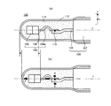
図1は本発明の第1の実施例としての温度センサの要部の構成を示す説明図であり、金属チューブ112のみを破断して示している。また、図7は第1の実施例としての温度センサの全体構成を示す説明図であり、一部を破断して示している。なお、図1は、図7において、2本の素子電極線104のうちの一方を含む形で、紙面に垂直な向きに温度センサ100の中心軸線に平行な断面をとったときの要部拡大図に相当する。
図4は本発明の第2の実施例としての温度センサの構成を示す説明図であり、金属チューブ112のみ破断して示している。
図5は本発明の第3の実施例としての温度センサの構成を示す説明図であり、金属チューブ112のみ破断して示している。図5に示す破断面は、図1や図4に示した破断面と異なり、基準線Zを軸とした軸周りに、図1や図4に示した破断面より90度隔てた破断面を示している。
なお、本発明は上記した実施例や実施形態に限られるものではなく、その要旨を逸脱しない範囲において種々の態様にて実施することが可能である。
102…サーミスタ素子
103…サーミスタ焼結体
104…素子電極線
104a…屈曲部
106…シース部材
107…シース管
108,109…シース芯線
110…接合部
112…金属チューブ
114…セメント
200…温度センサ
204…素子電極線
204a…屈曲部
208…シース芯線
300…温度センサ
304,305…素子電極線
304a,305a…屈曲部
500…温度センサ
502…サーミスタ素子
503…サーミスタ焼結体
504…素子電極線
506…シース部材
507…シース管
508…シース芯線
510…接合部
512…金属チューブ
514…セメント
Claims (6)
- 感温部と、前記感温部に接続されると共に当該感温部の後方側に向かって延びる素子電極線とを有する感温素子と、
前記素子電極線に接合されるシース芯線と、前記シース芯線を絶縁保持した状態で内包してなる外管とを有するシース部材と、
先端側に底部が形成された有底筒状をなし、少なくとも、前記感温素子、及び前記素子電極線と前記シース芯線との接合部を包囲する金属製の包囲部材と、
前記包囲部材に包囲された空間のうち、少なくとも前記感温部の先端面と前記底部との間の領域に充填される保持部材と、
を備えた温度センサであって、
前記素子電極線は、前記感温部から延びて前記接合部に至るまでの部位に、屈曲してなる屈曲部を有することを特徴とする温度センサ。 - 請求項1に記載の温度センサにおいて、
前記屈曲部は、アーチ形状に屈曲していることを特徴とする温度センサ。 - 請求項1または請求項2に記載の温度センサにおいて、
前記包囲部材に包囲された領域を、前記シース部材の外管の中心軸を含む所定の基準平面を境界面として、第1及び第2の領域に分離した場合に、
前記外管の先端から延びる前記シース芯線は、その先端部が第2の領域に位置するように、屈曲しており、
前記屈曲部は、前記第1の領域側に凸となるような形状に屈曲しており、
前記素子電極線は、前記シース芯線の先端部に接合しているとともに、前記接合部において、前記シース芯線よりも、第1の領域側に配置されていることを特徴とする温度センサ。 - 請求項1または請求項2に記載の温度センサにおいて、
前記シース部材の外管の中心軸を含む所定の基準軸を設定した場合に、
前記外管の先端から延びる前記シース芯線は、直線状を成すとともに、
前記屈曲部は、前記素子電極線を前記シース芯線に接合した際に前記感温素子の前記感温部が前記基準軸上に位置するように屈曲していることを特徴とする温度センサ。 - 請求項1または請求項2に記載の温度センサにおいて、
前記シース部材の外管の中心軸を含む所定の基準平面を設定した場合に、
前記屈曲部は、前記基準平面内に含まれていることを特徴とする温度センサ。 - 請求項1ないし請求項5のうちの任意の1つに記載の温度センサにおいて、
前記素子電極線は、前記感温部の後端面から突き出すようにして後端側に延びていることを特徴とする温度センサ。
Priority Applications (3)
| Application Number | Priority Date | Filing Date | Title |
|---|---|---|---|
| JP2007313809A JP4956397B2 (ja) | 2007-12-04 | 2007-12-04 | 温度センサ |
| EP08020910.9A EP2068137B1 (en) | 2007-12-04 | 2008-12-02 | Temperature sensor |
| US12/326,175 US8092086B2 (en) | 2007-12-04 | 2008-12-02 | Temperature sensor |
Applications Claiming Priority (1)
| Application Number | Priority Date | Filing Date | Title |
|---|---|---|---|
| JP2007313809A JP4956397B2 (ja) | 2007-12-04 | 2007-12-04 | 温度センサ |
Publications (2)
| Publication Number | Publication Date |
|---|---|
| JP2009139147A JP2009139147A (ja) | 2009-06-25 |
| JP4956397B2 true JP4956397B2 (ja) | 2012-06-20 |
Family
ID=40428264
Family Applications (1)
| Application Number | Title | Priority Date | Filing Date |
|---|---|---|---|
| JP2007313809A Active JP4956397B2 (ja) | 2007-12-04 | 2007-12-04 | 温度センサ |
Country Status (3)
| Country | Link |
|---|---|
| US (1) | US8092086B2 (ja) |
| EP (1) | EP2068137B1 (ja) |
| JP (1) | JP4956397B2 (ja) |
Families Citing this family (13)
| Publication number | Priority date | Publication date | Assignee | Title |
|---|---|---|---|---|
| DE102007036693A1 (de) * | 2007-08-03 | 2009-02-05 | Abb Ag | Thermometer mit auswechselbarem Messeinsatz und Verfahren zum Austausch desselben |
| JP5198934B2 (ja) * | 2008-05-09 | 2013-05-15 | 日本特殊陶業株式会社 | 温度センサ |
| JP4541436B2 (ja) * | 2008-11-27 | 2010-09-08 | 日本特殊陶業株式会社 | 温度センサ |
| DE202009011860U1 (de) * | 2009-09-02 | 2010-03-04 | Türk & Hillinger GmbH | Hochtemperaturstecker |
| DE102010031917B3 (de) * | 2010-07-22 | 2012-02-02 | Borgwarner Beru Systems Gmbh | Temperatursensor |
| DE102010050216B4 (de) | 2010-11-04 | 2015-01-08 | Heraeus Sensor Technology Gmbh | Turboladerüberhitzungsschutzeinrichtung und Verfahren zu ihrer Herstellung |
| JP5561292B2 (ja) * | 2012-03-06 | 2014-07-30 | 株式会社デンソー | 温度センサ |
| JP5814991B2 (ja) * | 2012-10-01 | 2015-11-17 | 日本特殊陶業株式会社 | 温度センサ |
| DE102014108097B4 (de) * | 2014-06-10 | 2016-11-24 | Heraeus Sensor Technology Gmbh | Temperatursensor, Abgastemperaturüberwachungssystem und Verfahren zur Herstellung des Temperatursensors |
| JP7042087B2 (ja) * | 2018-01-15 | 2022-03-25 | 株式会社Soken | 温度センサ |
| US12487134B2 (en) * | 2021-02-05 | 2025-12-02 | Sensata Technologies, Inc. | System and method for improving temperature detectors using expansion/contraction devices |
| WO2023101931A1 (en) * | 2021-12-02 | 2023-06-08 | Therm-O-Disc, Incorporated | Sensor with integral seal |
| US20240280413A1 (en) * | 2022-08-04 | 2024-08-22 | Shibaura Electronics Co., Ltd. | Temperature sensor and rotary electric machine |
Family Cites Families (8)
| Publication number | Priority date | Publication date | Assignee | Title |
|---|---|---|---|---|
| US4560973A (en) * | 1983-11-15 | 1985-12-24 | Daimler-Benz Aktiengesellschaft | Rod shaped thermometer and method of making same |
| JPH10318851A (ja) * | 1997-05-20 | 1998-12-04 | Matsushita Electric Ind Co Ltd | 温度センサとその製造方法 |
| JP3800798B2 (ja) * | 1998-04-08 | 2006-07-26 | 株式会社デンソー | 温度センサ素子 |
| JP3975023B2 (ja) | 1999-03-19 | 2007-09-12 | 日本特殊陶業株式会社 | 温度センサ |
| JP3705362B2 (ja) * | 2002-03-15 | 2005-10-12 | 株式会社生方製作所 | 密閉型感熱装置 |
| JP4765871B2 (ja) * | 2005-11-09 | 2011-09-07 | 株式会社デンソー | 温度センサ |
| DE102006034248B3 (de) * | 2006-07-21 | 2007-10-18 | Beru Ag | Temperaturfühler für ein Widerstandsthermometer, insbesondere zur Verwendung im Abgasstrang von Verbrennungsmotoren |
| DE102007010403B4 (de) * | 2007-03-01 | 2016-02-11 | Heraeus Sensor Technology Gmbh | Temperatursensor und dessen Verwendung in einer Turboladerüberhitzungssicherung |
-
2007
- 2007-12-04 JP JP2007313809A patent/JP4956397B2/ja active Active
-
2008
- 2008-12-02 US US12/326,175 patent/US8092086B2/en active Active
- 2008-12-02 EP EP08020910.9A patent/EP2068137B1/en active Active
Also Published As
| Publication number | Publication date |
|---|---|
| EP2068137B1 (en) | 2017-08-23 |
| US20090147826A1 (en) | 2009-06-11 |
| JP2009139147A (ja) | 2009-06-25 |
| EP2068137A3 (en) | 2011-05-04 |
| US8092086B2 (en) | 2012-01-10 |
| EP2068137A2 (en) | 2009-06-10 |
Similar Documents
| Publication | Publication Date | Title |
|---|---|---|
| JP4956397B2 (ja) | 温度センサ | |
| US7553078B2 (en) | Temperature sensor and method for producing the same | |
| JP5134701B2 (ja) | 温度センサ | |
| US8256956B2 (en) | Temperature sensor | |
| JP5155246B2 (ja) | 温度センサ | |
| JP2002289407A (ja) | 温度センサおよびその製造方法 | |
| JP5252631B2 (ja) | 温度センサおよびその製造方法 | |
| JPH04319634A (ja) | 温度センサ | |
| JP2018100965A (ja) | 高温排出センサ | |
| JP2009300237A (ja) | 温度センサおよびその製造方法 | |
| JP2002168702A (ja) | 温度センサ | |
| JP2007327893A (ja) | 温度センサ | |
| JP4059222B2 (ja) | 温度センサ及び温度センサの製造方法 | |
| JP4192067B2 (ja) | ガスセンサ | |
| JP2008096215A (ja) | 高圧領域内温度測定用シース熱電対、及びその製造方法 | |
| JP2006078236A (ja) | カプセル型ひずみゲージ、カプセル型ひずみゲージの製造方法およびカプセル型ひずみゲージの取付方法 | |
| JP3108015U (ja) | シース熱電対先端パッド | |
| JP2002267546A (ja) | 温度センサ | |
| CN219087722U (zh) | 热电偶 | |
| JP6554979B2 (ja) | 圧力センサ | |
| CN110715751B (zh) | 温度传感器 | |
| JP2011027450A (ja) | 温度センサ | |
| JP2002267540A (ja) | 温度センサ | |
| JPS639974Y2 (ja) | ||
| CN117998961A (zh) | 热电偶 |
Legal Events
| Date | Code | Title | Description |
|---|---|---|---|
| A621 | Written request for application examination |
Free format text: JAPANESE INTERMEDIATE CODE: A621 Effective date: 20100914 |
|
| A977 | Report on retrieval |
Free format text: JAPANESE INTERMEDIATE CODE: A971007 Effective date: 20120216 |
|
| TRDD | Decision of grant or rejection written | ||
| A01 | Written decision to grant a patent or to grant a registration (utility model) |
Free format text: JAPANESE INTERMEDIATE CODE: A01 Effective date: 20120221 |
|
| A01 | Written decision to grant a patent or to grant a registration (utility model) |
Free format text: JAPANESE INTERMEDIATE CODE: A01 |
|
| A61 | First payment of annual fees (during grant procedure) |
Free format text: JAPANESE INTERMEDIATE CODE: A61 Effective date: 20120316 |
|
| R150 | Certificate of patent or registration of utility model |
Free format text: JAPANESE INTERMEDIATE CODE: R150 Ref document number: 4956397 Country of ref document: JP Free format text: JAPANESE INTERMEDIATE CODE: R150 |
|
| FPAY | Renewal fee payment (event date is renewal date of database) |
Free format text: PAYMENT UNTIL: 20150323 Year of fee payment: 3 |
|
| R250 | Receipt of annual fees |
Free format text: JAPANESE INTERMEDIATE CODE: R250 |
|
| R250 | Receipt of annual fees |
Free format text: JAPANESE INTERMEDIATE CODE: R250 |
|
| R250 | Receipt of annual fees |
Free format text: JAPANESE INTERMEDIATE CODE: R250 |
|
| R250 | Receipt of annual fees |
Free format text: JAPANESE INTERMEDIATE CODE: R250 |
|
| R250 | Receipt of annual fees |
Free format text: JAPANESE INTERMEDIATE CODE: R250 |
|
| R250 | Receipt of annual fees |
Free format text: JAPANESE INTERMEDIATE CODE: R250 |
|
| R250 | Receipt of annual fees |
Free format text: JAPANESE INTERMEDIATE CODE: R250 |
|
| R250 | Receipt of annual fees |
Free format text: JAPANESE INTERMEDIATE CODE: R250 |
|
| S531 | Written request for registration of change of domicile |
Free format text: JAPANESE INTERMEDIATE CODE: R313531 |
|
| R350 | Written notification of registration of transfer |
Free format text: JAPANESE INTERMEDIATE CODE: R350 |
|
| R250 | Receipt of annual fees |
Free format text: JAPANESE INTERMEDIATE CODE: R250 |
|
| R250 | Receipt of annual fees |
Free format text: JAPANESE INTERMEDIATE CODE: R250 |
|
| R250 | Receipt of annual fees |
Free format text: JAPANESE INTERMEDIATE CODE: R250 |