JP4956397B2 - Temperature sensor - Google Patents
Temperature sensor Download PDFInfo
- Publication number
- JP4956397B2 JP4956397B2 JP2007313809A JP2007313809A JP4956397B2 JP 4956397 B2 JP4956397 B2 JP 4956397B2 JP 2007313809 A JP2007313809 A JP 2007313809A JP 2007313809 A JP2007313809 A JP 2007313809A JP 4956397 B2 JP4956397 B2 JP 4956397B2
- Authority
- JP
- Japan
- Prior art keywords
- temperature sensor
- sheath
- element electrode
- bent
- core wire
- Prior art date
- Legal status (The legal status is an assumption and is not a legal conclusion. Google has not performed a legal analysis and makes no representation as to the accuracy of the status listed.)
- Active
Links
Images


Classifications
-
- G—PHYSICS
- G01—MEASURING; TESTING
- G01K—MEASURING TEMPERATURE; MEASURING QUANTITY OF HEAT; THERMALLY-SENSITIVE ELEMENTS NOT OTHERWISE PROVIDED FOR
- G01K1/00—Details of thermometers not specially adapted for particular types of thermometer
- G01K1/08—Protective devices, e.g. casings
-
- G—PHYSICS
- G01—MEASURING; TESTING
- G01K—MEASURING TEMPERATURE; MEASURING QUANTITY OF HEAT; THERMALLY-SENSITIVE ELEMENTS NOT OTHERWISE PROVIDED FOR
- G01K13/00—Thermometers specially adapted for specific purposes
- G01K13/02—Thermometers specially adapted for specific purposes for measuring temperature of moving fluids or granular materials capable of flow
- G01K13/024—Thermometers specially adapted for specific purposes for measuring temperature of moving fluids or granular materials capable of flow of moving gases
-
- G—PHYSICS
- G01—MEASURING; TESTING
- G01K—MEASURING TEMPERATURE; MEASURING QUANTITY OF HEAT; THERMALLY-SENSITIVE ELEMENTS NOT OTHERWISE PROVIDED FOR
- G01K2205/00—Application of thermometers in motors, e.g. of a vehicle
- G01K2205/04—Application of thermometers in motors, e.g. of a vehicle for measuring exhaust gas temperature
Landscapes
- Physics & Mathematics (AREA)
- General Physics & Mathematics (AREA)
- Measuring Temperature Or Quantity Of Heat (AREA)
Description
本発明は、サーミスタ素子やPt抵抗体素子等の感温素子を備える温度センサに関するものである。 The present invention relates to a temperature sensor including a temperature sensitive element such as a thermistor element or a Pt resistor element.
従来、自動車の排気ガスなどの温度を検出するための温度センサとしては、下記の特許文献1に記載のものが知られている。 Conventionally, as a temperature sensor for detecting the temperature of exhaust gas or the like of an automobile, one described in Patent Document 1 below is known.
図6は従来の温度センサの構成を示す断面図であり、金属チューブ512のみを破断して示している。図6(a)に示すように、この温度センサ500は、サーミスタ焼結体503と素子電極線504とから構成されるサーミスタ素子502と、シース芯線508をシース管507内に絶縁保持してなるシース部材506とを備えている。そして、サーミスタ焼結体503から延びる素子電極線504はシース管507の先端から延びるシース芯線508に、レーザスポット溶接によって接合されてなり、サーミスタ素子502及びその接合部510がステンレス合金製の金属チューブ512内に収容されると共に、それら収容されたサーミスタ素子502などを保持するために、その金属チューブ512で囲まれた空間に、耐熱性酸化物(Al2O3[アルミナ]など)から成るセメント514が充填されることによって、温度センサ500は構成されている。
FIG. 6 is a cross-sectional view showing the structure of a conventional temperature sensor, in which only the
排気ガスなどの温度は、0℃前後の低温域から1000℃前後の高温域までの広い範囲にわたって変化するため、この温度センサ500は、そのような広範囲の温度を検出するのに使用される。従って、この温度センサ500は、低温/高温の冷熱サイクルの環境下に曝されることになる。
The temperature of the exhaust gas or the like varies over a wide range from a low temperature range of around 0 ° C. to a high temperature range of around 1000 ° C., and thus the
従来の温度センサ500においては、上記したとおり、冷熱サイクルの環境下に曝されるため、高温から低温へ急冷された際、外周を構成する部材、すなわち、有底筒状の金属チューブ512から冷却が始まることになる。この時、金属チューブ512は、ステンレス合金製であり、金属チューブ512で囲われた空間に充填されたセメント514は、アルミナであるため、熱膨張係数を比較すると、ステンレス合金の方がアルミナよりも高い。従って、図6(b)に示すように、金属チューブ512が冷却により収縮し始めると、セメント514の収縮がそれに追従できず、そのため、金属チューブ512の先端部(底部)が、内部のセメント514を矢印A方向に押圧し、それにより、セメント514に保持されているサーミスタ素子502(詳細には、サーミスタ焼結体503)の先端面もシース部材506側(後方側)に向かって押圧されることになる。こうして、サーミスタ素子502がシース部材506側に向かって押圧されると、素子電極線504とシース芯線508との接合部510に、矢印Bで示すように、剪断応力が加わってしまう。
Since the
このように、素子電極線504とシース芯線508との接合部510に、剪断応力が冷熱サイクルが繰り返されるたびに加わると、最悪の場合、この接合部510が破断していまい、サーミスタ素子502からの検出出力を外部に取り出せなくなってしまうおそれがあった。
In this way, when shear stress is applied to the
従って、本発明の目的は、上記した従来技術の問題点を解決し、素子電極線とシース芯線との接合部に加わる剪断応力を緩和することができる温度センサを提供することにある。 Accordingly, an object of the present invention is to provide a temperature sensor that solves the above-described problems of the prior art and can relieve the shear stress applied to the joint between the element electrode wire and the sheath core wire.
本発明は、上述の課題の少なくとも一部を解決するためになされたものであり、以下の形態又は適用例として実現することが可能である。 SUMMARY An advantage of some aspects of the invention is to solve at least a part of the problems described above, and the invention can be implemented as the following forms or application examples.
[適用例1]
感温部と、前記感温部に接続されると共に当該感温部の後方側に向かって延びる素子電極線とを有する感温素子と、
前記素子電極線に接合されるシース芯線と、前記シース芯線を絶縁保持した状態で内包してなる外管とを有するシース部材と、
先端側に底部が形成された有底筒状をなし、少なくとも、前記感温素子、及び前記素子電極線と前記シース芯線との接合部を包囲する金属製の包囲部材と、
前記包囲部材に包囲された空間のうち、少なくとも前記感温部の先端面と前記底部との間の領域に充填される保持部材と、
を備えた温度センサであって、
前記素子電極線は、前記感温部から延びて前記接合部に至るまでの部位に、屈曲してなる屈曲部を有することを特徴とする温度センサ。
[Application Example 1]
A temperature sensing element having a temperature sensing part and an element electrode line connected to the temperature sensing part and extending toward the rear side of the temperature sensing part;
A sheath member having a sheath core wire joined to the element electrode wire, and an outer tube encapsulated in a state in which the sheath core wire is insulated and held;
A bottomed cylindrical shape with a bottom formed on the distal end side, and at least the temperature sensing element, and a metal surrounding member that surrounds the junction between the element electrode wire and the sheath core; and
Of the space surrounded by the surrounding member, at least a holding member filled in a region between the tip surface of the temperature sensing portion and the bottom portion;
A temperature sensor comprising:
The temperature sensor characterized in that the element electrode wire has a bent portion that is bent at a portion extending from the temperature sensing portion to the joint portion.
このように、適用例1の温度センサでは、素子電極線が屈曲部を有しているため、例えば、急冷により、包囲部材が収縮し、保持部材の収縮がそれに追従できず、包囲部材が保持部材を介して感温素子(詳細には、感温部の先端面)をシース部材側に向かって押圧したとしても、屈曲部が変形することにより、その押圧力を分散させることができ、素子電極線とシース芯線との接合部に加わる剪断応力を緩和することができる。 Thus, in the temperature sensor of Application Example 1, since the element electrode wire has a bent portion, the surrounding member contracts due to, for example, rapid cooling, and the contraction of the holding member cannot follow it, and the surrounding member holds. Even if the temperature-sensitive element (specifically, the tip surface of the temperature-sensitive part) is pressed toward the sheath member side through the member, the pressing force can be dispersed by the deformation of the bent part. The shear stress applied to the joint between the electrode wire and the sheath core wire can be relaxed.
[適用例2]
適用例1に記載の温度センサにおいて、前記屈曲部は、アーチ形状に屈曲していることを特徴とする温度センサ。
[Application Example 2]
The temperature sensor according to Application Example 1, wherein the bent portion is bent in an arch shape.
このように、屈曲部がアーチ形状を成すことにより、感温素子がシース部材側に向かって押圧された場合に、その押圧力を確実に分散させることができる。また、素子電極線をアーチ形状に屈曲させることは比較的容易であるため、屈曲加工を施す時間を短縮することができる。 Thus, when the temperature-sensitive element is pressed toward the sheath member, the pressing force can be reliably dispersed by forming the bent portion in an arch shape. In addition, since it is relatively easy to bend the element electrode lines into an arch shape, the time for performing the bending process can be shortened.
[適用例3]
適用例1または適用例2に記載の温度センサにおいて、前記包囲部材に包囲された領域を、前記シース部材の外管の中心軸を含む所定の基準平面を境界面として、第1及び第2の領域に分離した場合に、前記外管の先端から延びる前記シース芯線は、その先端部が第2の領域に位置するように、屈曲しており、前記屈曲部は、前記第1の領域側に凸となるような形状に屈曲しており、前記素子電極線は、前記シース芯線の先端部に接合しているとともに、前記接合部において、前記シース芯線よりも、第1の領域側に配置されていることを特徴とする温度センサ。
[Application Example 3]
In the temperature sensor according to Application Example 1 or Application Example 2, the region surrounded by the surrounding member may be a first reference plane and a second reference plane with a predetermined reference plane including a central axis of the outer tube of the sheath member as a boundary surface. When separated into regions, the sheath core wire extending from the distal end of the outer tube is bent so that the distal end portion is located in the second region, and the bent portion is located on the first region side. The element electrode wire is joined to the distal end portion of the sheath core wire, and is disposed closer to the first region than the sheath core wire at the joint portion. A temperature sensor characterized by having
適用例3の温度センサでは、素子電極線の屈曲部が第1の領域側に凸となるような形状に屈曲しているため、素子電極線をシース芯線よりも第1の領域側に配置して、両者を接合する場合に、屈曲部がシース芯線の先端部と干渉するおそれがない。また、シース芯線は、その先端部が第2の領域に位置しているため、素子電極線をシース芯線よりも第1の領域側に配置して、両者を接合したとしても、感温素子を基準平面に位置させることができる。また、素子電極線の屈曲部が第1の領域側に凸となるような形状に屈曲していても、屈曲部が、包囲部材の内壁面に接触するおそれがない。
なお、ここで、シース部材の外管の中心軸とは、外管の中心を、外管の方向に沿って貫く軸を言う。
In the temperature sensor of Application Example 3, since the bent portion of the element electrode wire is bent so as to protrude toward the first region, the element electrode wire is arranged closer to the first region than the sheath core wire. Thus, when joining the two, there is no possibility that the bent portion interferes with the distal end portion of the sheath core wire. In addition, since the distal end portion of the sheath core wire is located in the second region, even if the device electrode wire is disposed closer to the first region than the sheath core wire and the two are joined, It can be located in a reference plane. Further, even if the bent portion of the element electrode line is bent in a shape that protrudes toward the first region, there is no possibility that the bent portion contacts the inner wall surface of the surrounding member.
Here, the central axis of the outer tube of the sheath member refers to an axis that penetrates the center of the outer tube along the direction of the outer tube.
[適用例4]
適用例1または適用例2に記載の温度センサにおいて、前記シース部材の外管の中心軸を含む所定の基準軸を設定した場合に、前記外管の先端から延びる前記シース芯線は、直線状を成すとともに、前記屈曲部は、前記素子電極線を前記シース芯線に接合した際に前記感温素子の前記感温部が前記基準軸上に位置するように屈曲していることを特徴とする温度センサ。
[Application Example 4]
In the temperature sensor according to Application Example 1 or Application Example 2, when a predetermined reference axis including a central axis of the outer tube of the sheath member is set, the sheath core wire extending from the distal end of the outer tube has a linear shape. And the bent portion is bent so that the temperature sensitive portion of the temperature sensitive element is located on the reference axis when the element electrode wire is joined to the sheath core wire. Sensor.
適用例4の温度センサでは、素子電極線の屈曲部が、このような形状に屈曲しているため、シース芯線を直線状としても、感温素子を基準軸上に位置させることができる。従って、適用例4の温度センサによれば、シース芯線に屈曲加工を施す必要がないため、その分、製造工程を簡素化することができる。 In the temperature sensor of Application Example 4, since the bent portion of the element electrode wire is bent in such a shape, the temperature sensitive element can be positioned on the reference axis even if the sheath core wire is linear. Therefore, according to the temperature sensor of Application Example 4, since it is not necessary to bend the sheath core wire, the manufacturing process can be simplified correspondingly.
[適用例5]
適用例1または適用例2に記載の温度センサにおいて、前記シース部材の外管の中心軸を含む所定の基準平面を設定した場合に、前記屈曲部は、前記基準平面内に含まれていることを特徴とする温度センサ。
[Application Example 5]
In the temperature sensor according to Application Example 1 or Application Example 2, when a predetermined reference plane including a central axis of the outer tube of the sheath member is set, the bent portion is included in the reference plane. Temperature sensor.
このように、素子電極線の屈曲部は、基準平面内に含まれているように構成してもよく、このような構成であっても、適用例1の温度センサと同様の効果を奏することができる。 As described above, the bent portion of the element electrode line may be configured to be included in the reference plane, and even with such a configuration, the same effect as the temperature sensor of Application Example 1 can be obtained. Can do.
[適用例6]
適用例1ないし適用例のうちの任意の1つに記載の温度センサにおいて、前記素子電極線は、前記感温部の後端面から突き出すようにして後端側に延びていることを特徴とする温度センサ。
[Application Example 6]
In the temperature sensor according to any one of the application examples 1 to 1, the element electrode wire extends to the rear end side so as to protrude from the rear end surface of the temperature sensing unit. Temperature sensor.
このように、素子電極線が感温部の後端面から突き出すようにして後端側に延びていることによって、感温素子が前面から押圧された場合に、その押圧力を後端面から素子電極線に直接的に伝え、屈曲部で分散させることができる。 In this way, when the temperature sensitive element is pressed from the front surface by extending the element electrode wire from the rear end face so as to protrude from the rear end face of the temperature sensing portion, the pressing force is applied from the rear end face to the element electrode. It can be transmitted directly to the wire and dispersed at the bend.
なお、本発明は、上記した温度センサなどの装置発明の態様に限ることなく、温度検出方法などの方法発明としての態様で実現することも可能である。 The present invention is not limited to the above-described aspects of the device invention such as the temperature sensor, but can also be realized as a method invention such as a temperature detection method.
A.第1の実施例:
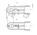
図1は本発明の第1の実施例としての温度センサの要部の構成を示す説明図であり、金属チューブ112のみを破断して示している。また、図7は第1の実施例としての温度センサの全体構成を示す説明図であり、一部を破断して示している。なお、図1は、図7において、2本の素子電極線104のうちの一方を含む形で、紙面に垂直な向きに温度センサ100の中心軸線に平行な断面をとったときの要部拡大図に相当する。
A. First embodiment:
FIG. 1 is an explanatory view showing a configuration of a main part of a temperature sensor as a first embodiment of the present invention, in which only a
本実施例の温度センサ100は、自動車の排気ガスの温度を検出するために用いられる。従って、この温度センサ100は、0℃前後の低温域から1000℃前後の高温域までの広い範囲にわたって温度変化を生じ得る、冷熱サイクルの環境下に曝されることになる。
The
まず、図7に示すように、温度センサ100は、有底筒状の金属チューブ112の先端部内側に、サーミスタ素子102を配置させてなる。金属チューブ112の後端側は開放されており、この後端部は、フランジ部材140の内側に圧入されている。フランジ部材140は、軸線方向に延びる筒状の鞘部143と、この鞘部143の先端側に位置し、この鞘部よりも大きい外径を有して径方向外側に突出する鍔部142とを備えている。鍔部142の先端側には排気ガスが流れる排気管の取付部とシールを行うテーパ状の座面145を有している。なお、鞘部42は、先端側に位置する第1段部144とこれよりも径小の第2段部6とからなる二段形状をなしている。
First, as shown in FIG. 7, the
そして、フランジ部材140に圧入された金属チューブ112は、その外周面が第2段部146と全周レーザ溶接されている。また、フランジ部材140の第1段部144には、円筒形状の金属製の継手160が圧入され、全周レーザ溶接されている。フランジ部材140及び継手160の周囲には、六角ナット部151及びネジ部152を有する取り付け部材150が回動自在に設けられている。本実施例の温度センサ100は、排気管の取付部にフランジ部材140の座面145を当接させ、取り付け部材150を取付部に螺合させることで、排気管に固定される。
The outer circumference of the
金属チューブ112、フランジ部材140及び継手160の内側には、2本のシース芯線108をシース管107の内部に絶縁保持させたシース部材106が配置されている。金属チューブ112の内部においてシース部材106のシース管107の先端から延びるシース芯線108には、サーミスタ素子102の素子電極線104がレーザスポット溶接されている。一方、シース部材106から後端側に延びるシース芯線108は、加締め端子172を介して2本のリード線173に接続されている。シース芯線108同士及び加締め端子172同士は、絶縁チューブ171により互いに絶縁されている。この2本のリード線173は、継手160の後端部内側に嵌められた弾性シール部材174のリード線挿通孔を通って、継手160の外部に向けって引き出され、図示しないコネクタを介して外部回路と接続されることになる。
Inside the
次いで、第1の実施例の要部について、図1(a)を用いて説明する。サーミスタ素子102は、サーミスタ焼結体103と素子電極線104とから構成されている。サーミスタ焼結体103は、(Sr,Y)(Al,Mn,Fe)03をベース組成としたペロブスカイト型酸化物で形成されている。サーミスタ焼結体103は、六角柱形状を成しており、その後端面からは2本の素子電極線104が延びている。また、シース部材106は、ステンレス合金製のシース管107の内部に、2本のシース芯線108を配置し、そのシース芯線108を保持すべく、シース充填材(図示せず)を充填することにより、構成されている。そして、そのシース管107の先端からは、2本のシース芯線108が延びている。サーミスタ素子102の2本の素子電極線104と、シース部材106の2本のシース芯線108とは、それぞれ、断面が円形状を成しており、互いに対応する線同士の先端部がそれぞれ重ね合わされて、レーザスポット溶接によって接合されている。金属チューブ112は、有底筒状を成し、ステンレス合金製であり、その内部に、サーミスタ素子102と、レーザスポット溶接による接合部110と、シース部材106の一部と、を収容している。さらに、セメント114は、絶縁セラミック成分、具体的にはAl2O3(アルミナ)を主体とし、シリカを骨材として含有させた耐熱性酸化物によって構成されており、金属チューブ112によって囲まれた空間内に充填されることにより、サーミスタ素子102や接合部110などを保持するようにしている。
Next, the main part of the first embodiment will be described with reference to FIG. The
なお、本実施例において、サーミスタ素子102は、請求項における感温素子に、金属チューブ112は、請求項における包囲部材に、セメント114は、請求項における保持部材に、それぞれ相当している。
In this embodiment, the
図1において、X,Yは座標軸を表しており、紙面に沿った方向がY軸,紙面に垂直な方向がX軸である。また、基準線Zは、温度センサ100の中心線であり、シース部材106におけるシース管107の中心軸を含んでいる。今、紙面に垂直な平面であって、この基準線Zを含む基準平面を想定した場合、金属チューブ112によって囲まれた領域は、その基準平面を境界面として、上側の領域(Y軸方向+側の領域)と下側の領域(Y軸方向−側の領域)とに分離することができる。
In FIG. 1, X and Y represent coordinate axes, the direction along the paper surface is the Y axis, and the direction perpendicular to the paper surface is the X axis. The reference line Z is a center line of the
本実施例において、シース管107の先端から延びるシース芯線108は、図1(a)に示すように、基準平面に沿って直線状に延びた後、下側の領域に向かって斜めに屈曲し、さらに、基準平面に平行になるように屈曲している。従って、その先端部は、下側の領域に位置している。
In this embodiment, the
一方、サーミスタ焼結体103から延びる素子電極線104は、基準平面に沿って直線状に延びているが、その途中が、上側の領域に向かってアーチ形状となるように屈曲して、屈曲部104aを形成している。
On the other hand, the
そして、素子電極線104とシース芯線108とは、素子電極線104を上側(Y軸方向+側)、シース芯線108を下側(Y軸方向−側)として、接合されている。
The
さて、本実施例においても、温度センサ100は、冷熱サイクルの環境下に曝されるため、高温から低温へ急冷された際、外周を構成する金属チューブ112から冷却が始まることになる。この時、金属チューブ112は、ステンレス合金製であり、金属チューブ112で囲われた空間に充填されたセメント114は、アルミナを主体としているため、前述したとおり、熱膨張係数を比較すると、ステンレス合金の方がアルミナよりも高い。従って、金属チューブ112が冷却により収縮し始めると、セメント114の収縮がそれに追従できない。そのため、図1(b)に示すように、金属チューブ112の先端部(底部)が、内部のセメント114を矢印A方向に押圧すると、セメント114に保持されているサーミスタ素子102(詳細には、サーミスタ焼結体103の先端面)もシース部材106側(後方側)に向かって押圧されることになる。しかしながら、上述したとおり、サーミスタ焼結体103から延びる素子電極線104は、その途中に屈曲部104aを有しているため、例え、サーミスタ素子102がシース部材106側に向かって押圧されても、屈曲部104aが先行して変形することにより、その押圧力を分散させることができる。従って、素子電極線504とシース芯線508との接合部510に、矢印Bで示すように、剪断応力が加わったとしても、その剪断応力を大幅に緩和することができる。
In the present embodiment, since the
また、本実施例では、素子電極線104の屈曲部104aは、上側(Y軸方向+側)に凸となる形状となっているため、素子電極線104を上側(Y軸方向+側)、シース芯線108を下側(Y軸方向−側)として、両者を接合する場合に、その屈曲部104aがシース芯線108の先端部と干渉するおそれがない。
In the present embodiment, the
これに対し、仮に、図2に示すように、素子電極線104の屈曲部104aが、下側(Y軸方向−側)に凸となる形状となっている場合には、素子電極線104を上側(Y軸方向+側)、シース芯線108を下側(Y軸方向−側)として、両者を接合する際に、C部において、屈曲部104aがシース芯線108の先端部と干渉してしまい、素子電極線104とシース部材106とが密着せず、適正な接合が行えないおそれがある。
On the other hand, as shown in FIG. 2, if the
また、本実施例では、シース芯線108は、上述したように、その先端部が下側の領域に位置しているため、素子電極線104を上側(Y軸方向+側)、シース芯線108を下側(Y軸方向−側)として、両者を接合したとしても、サーミスタ素子102を基準平面に位置させることができる。このように、サーミスタ素子102を基準平面に位置させることができれば、金属チューブ112を介して各方向から均等に熱が伝達されるため、サーミスタ素子102は、排気ガスの温度を精度よく検出することができる。
In the present embodiment, as described above, the
さらに、本実施例では、シース芯線108の先端部が下側の領域に位置しているため、素子電極線104の屈曲部104aが、上側(Y軸方向+側)に凸となる形状となっていても、屈曲部104aが、金属チューブ112の内壁面に接触するおそれがない。
Furthermore, in this embodiment, since the distal end portion of the
これに対し、仮に、図3に示すように、シース芯線108の先端部が上側の領域に位置している場合、素子電極線104を上側(Y軸方向+側)、シース芯線108を下側(Y軸方向−側)として、両者を接合したとすると、サーミスタ素子102は、上側の領域に位置してしまい、基準平面に配置させることができない。また、素子電極線104の屈曲部104aが、上側(Y軸方向+側)に凸となる形状となっていると、屈曲部104aやサーミスタ焼結体103が、金属チューブ112の内壁面に接触するおそれがでてくる。
On the other hand, as shown in FIG. 3, when the tip of the
以上、説明したとおり、本実施例によれば、サーミスタ焼結体103から延びる素子電極線104が、その途中に屈曲部104aを有しているため、素子電極線104とシース芯線108との接合部110に加わる剪断応力を大幅に緩和することができるという効果を奏する。
As described above, according to the present embodiment, the
B.第2の実施例:
図4は本発明の第2の実施例としての温度センサの構成を示す説明図であり、金属チューブ112のみ破断して示している。
B. Second embodiment:
FIG. 4 is an explanatory view showing the structure of a temperature sensor as a second embodiment of the present invention, in which only the
本実施例の温度センサ200が、第1の実施例の温度センサ100と相違する点は、次の2点である。すなわち、第1の相違点は、図4に示すように、シース管107の先端から延びるシース芯線208が屈曲しておらず、直線状を成している点である。第2の相違点は、サーミスタ焼結体103から延びる素子電極線204が、基準平面に沿って直線状に延び、その途中に、上側の領域に向かってアーチ形状を成す屈曲部204aを有するものの、その屈曲部204aは、素子電極線204の先端部が、基準平面内ではなく、上側の領域に位置するような形状に屈曲している点である。その他の構成は、第1の実施例と同様であるので、同一の符号を付し、それらについての説明は省略する。
The
本実施例では、上述したように、素子電極線204の屈曲部204aは、素子電極線204の先端部が上側の領域に位置するような形状に屈曲しているため、シース芯線208を直線状としても、素子電極線104を上側(Y軸方向+側)、シース芯線108を下側(Y軸方向−側)として、両者を接合する場合、サーミスタ素子102を基準平面に位置させることができる。従って、本実施例によれば、シース芯線208に屈曲加工を施す必要がないため、その分、製造工程を簡素化することができる。
In this embodiment, as described above, the
また、本実施例においても、サーミスタ焼結体103から延びる素子電極線204が、その途中に屈曲部204aを有しているため、第1の実施例の場合と同様に、素子電極線204とシース芯線208との接合部110に加わる剪断応力を大幅に緩和することができるという効果を奏する。
Also in the present embodiment, the
C.第3の実施例:
図5は本発明の第3の実施例としての温度センサの構成を示す説明図であり、金属チューブ112のみ破断して示している。図5に示す破断面は、図1や図4に示した破断面と異なり、基準線Zを軸とした軸周りに、図1や図4に示した破断面より90度隔てた破断面を示している。
C. Third embodiment:
FIG. 5 is an explanatory view showing the structure of a temperature sensor as a third embodiment of the present invention, and only the
図5において、X,Yは座標軸を表しているが、上述したとおり、図1や図4の破断面より90度隔てた破断面であるため、紙面に垂直な方向がY軸,紙面に沿った方向がx軸となっている。また、第1及び第2の実施例で想定した、基準線Zを含む基準平面は、紙面に沿った平面となっている。 In FIG. 5, X and Y represent coordinate axes, but as described above, the fracture surface is 90 degrees apart from the fracture surface of FIGS. 1 and 4, so the direction perpendicular to the paper surface is along the Y axis and the paper surface. The direction is the x-axis. Further, the reference plane including the reference line Z assumed in the first and second embodiments is a plane along the paper surface.
本実施例の温度センサ300が、第1の実施例の温度センサ100と相違する点は、図5に示すように、サーミスタ焼結体103から延びる素子電極線304,305が、それぞれ、基準平面に沿って直線状に延び、その途中に、基準平面内において、互いにx軸方向において反対向きに向かってアーチ形状を成す屈曲部304a,305aを有する点である。その他の構成は、第1の実施例と同様であるので、同一の符号を付し、それらについての説明は省略するものとする。
The
このように、素子電極線304,305の屈曲部304a,305aは、それぞれ、基準平面内にあってもよい。また、本実施例では、各々の屈曲部304a,305aは、x軸方向において反対向きに向かって凸となっているため、互いに干渉し合うことがない。
Thus, the
また、本実施例においても、サーミスタ焼結体103から延びる素子電極線304,305が、その途中に屈曲部304a,305aを有しているため、第1の実施例の場合と同様に、素子電極線304,305とシース芯線108,109との接合部に加わる剪断応力を大幅に緩和することができるという効果を奏する。
Also in this embodiment, since the
D.変形例:
なお、本発明は上記した実施例や実施形態に限られるものではなく、その要旨を逸脱しない範囲において種々の態様にて実施することが可能である。
D. Variations:
The present invention is not limited to the above-described examples and embodiments, and can be implemented in various modes without departing from the scope of the invention.
上記した第1の実施例における説明では、図2,図3に示す構成について、それぞれ、問題と成り得る点を指摘したが、それらの点を解消することができるのであれば、図2,図3に示す構成を、本発明の実施形態の一つとして取り入れてもよい。 In the above description of the first embodiment, the points shown in FIG. 2 and FIG. 3 have been pointed out as problems, but if those points can be solved, FIG. The configuration shown in FIG. 3 may be adopted as one embodiment of the present invention.
また、サーミスタ焼結体から延びる2本の素子電極線の形状は、屈曲部の形状も含め、互いに異なる形状であってもよい。それに対応して、シース管の先端から延びる2本のシース芯線の形状も、互いに異なる形状であってもよい。 Further, the shape of the two element electrode lines extending from the thermistor sintered body may be different from each other including the shape of the bent portion. Correspondingly, the shapes of the two sheath core wires extending from the distal end of the sheath tube may be different from each other.
例えば、一方の素子電極線及びそれに接合されるシース芯線の形状が、第1の実施例で述べた形状であって、他方の素子電極線及びそれに接合されるシース芯線の形状が、第1の実施例で述べた形状とは上下反対向きの形状(すなわち、屈曲部が、下側(Y軸方向−側)に凸となる形状)となっていてもよい。このことは、第2の実施例で述べた形状を用いる場合であっても同様である。また、例えば、一方の素子電極線及びそれに接合されるシース芯線の形状が、第1の実施例で述べた形状であって、他方の素子電極線及びそれに接合されるシース芯線の形状が、第2の実施例で述べた形状であってもよい。また、他の実施例の組み合わせであってもよい。 For example, the shape of one element electrode wire and the sheath core wire joined thereto is the shape described in the first embodiment, and the shape of the other element electrode wire and the sheath core wire joined thereto is the first shape. The shape described in the embodiment may be an upside down shape (that is, a shape in which the bent portion protrudes downward (Y-axis direction-side)). This is the same even when the shape described in the second embodiment is used. Further, for example, the shape of one element electrode wire and the sheath core wire joined thereto is the shape described in the first embodiment, and the shape of the other element electrode wire and the sheath core wire joined thereto is the first shape. The shape described in the second embodiment may be used. Moreover, the combination of another Example may be sufficient.
上記した第1及び第2の実施例では、素子電極線の屈曲部は、基準平面に対し垂直な平面内に含まれており、第3の実施例では、素子電極線の屈曲部は、基準平面内に含まれていたが、本発明はこれに限定されるものではなく、素子電極線の屈曲部は、これら以外の平面内に含まれていてもよい。 In the first and second embodiments described above, the bent portion of the element electrode line is included in a plane perpendicular to the reference plane. In the third embodiment, the bent portion of the element electrode line is the reference plane. Although included in the plane, the present invention is not limited to this, and the bent portion of the element electrode line may be included in a plane other than these.
上記した各実施例では、素子電極線の屈曲部はアーチ形状を成していたが、本発明はこれに限定されるものではなく、他の形状であってもよい。例えば、三角形状、四角形状、その他多角形状、ジグザグ形状、らせん形状であってもよい。 In each of the embodiments described above, the bent portion of the element electrode line has an arch shape, but the present invention is not limited to this, and may have other shapes. For example, a triangular shape, a quadrangular shape, other polygonal shapes, a zigzag shape, or a spiral shape may be used.
上記した各実施例では、シース部材106の一部を、フランジ部材140に固定した金属チューブ112内に収容させた構成の温度センサを示したが、本発明はこれに限定されるものではない。例えば、シース部材106のシース管107をフランジ部材140の内側に固着させ、フランジ部材140の先端から突出するシース管107の外周に、サーミスタ素子102及び接合部110を収容する形態で有底筒状の金属キャップを溶接固定させた温度センサに、本発明を適用しても良い。なお、この場合、金属キャップが請求項の包囲部材に相当する。
In each of the above-described embodiments, the temperature sensor having a configuration in which a part of the
上記した各実施例では、セメントとして、Al2O3(アルミナ)を用いたが、MgOや、SiO2などを用いるようにしてもよい。 In each of the above embodiments, Al 2 O 3 (alumina) is used as the cement, but MgO, SiO 2 or the like may be used.
上記した各実施例では、感温素子として、サーミスタ素子を用いたが、本発明はこれに限定されるものではなく、Pt抵抗体素子等を用いるようにしてもよい。 In each of the embodiments described above, the thermistor element is used as the temperature sensitive element. However, the present invention is not limited to this, and a Pt resistor element or the like may be used.
100…温度センサ
102…サーミスタ素子
103…サーミスタ焼結体
104…素子電極線
104a…屈曲部
106…シース部材
107…シース管
108,109…シース芯線
110…接合部
112…金属チューブ
114…セメント
200…温度センサ
204…素子電極線
204a…屈曲部
208…シース芯線
300…温度センサ
304,305…素子電極線
304a,305a…屈曲部
500…温度センサ
502…サーミスタ素子
503…サーミスタ焼結体
504…素子電極線
506…シース部材
507…シース管
508…シース芯線
510…接合部
512…金属チューブ
514…セメント
DESCRIPTION OF
Claims (6)
前記素子電極線に接合されるシース芯線と、前記シース芯線を絶縁保持した状態で内包してなる外管とを有するシース部材と、
先端側に底部が形成された有底筒状をなし、少なくとも、前記感温素子、及び前記素子電極線と前記シース芯線との接合部を包囲する金属製の包囲部材と、
前記包囲部材に包囲された空間のうち、少なくとも前記感温部の先端面と前記底部との間の領域に充填される保持部材と、
を備えた温度センサであって、
前記素子電極線は、前記感温部から延びて前記接合部に至るまでの部位に、屈曲してなる屈曲部を有することを特徴とする温度センサ。 A temperature sensing element having a temperature sensing part and an element electrode line connected to the temperature sensing part and extending toward the rear side of the temperature sensing part;
A sheath member having a sheath core wire joined to the element electrode wire, and an outer tube encapsulated in a state in which the sheath core wire is insulated and held;
A bottomed cylindrical shape with a bottom formed on the distal end side, and at least the temperature sensing element, and a metal surrounding member that surrounds the junction between the element electrode wire and the sheath core; and
Of the space surrounded by the surrounding member, at least a holding member filled in a region between the tip surface of the temperature sensing portion and the bottom portion;
A temperature sensor comprising:
The temperature sensor characterized in that the element electrode wire has a bent portion that is bent at a portion extending from the temperature sensing portion to the joint portion.
前記屈曲部は、アーチ形状に屈曲していることを特徴とする温度センサ。 The temperature sensor according to claim 1,
The temperature sensor, wherein the bent portion is bent in an arch shape.
前記包囲部材に包囲された領域を、前記シース部材の外管の中心軸を含む所定の基準平面を境界面として、第1及び第2の領域に分離した場合に、
前記外管の先端から延びる前記シース芯線は、その先端部が第2の領域に位置するように、屈曲しており、
前記屈曲部は、前記第1の領域側に凸となるような形状に屈曲しており、
前記素子電極線は、前記シース芯線の先端部に接合しているとともに、前記接合部において、前記シース芯線よりも、第1の領域側に配置されていることを特徴とする温度センサ。 The temperature sensor according to claim 1 or 2,
When the region surrounded by the surrounding member is separated into the first and second regions with a predetermined reference plane including the central axis of the outer tube of the sheath member as a boundary surface,
The sheath core wire extending from the distal end of the outer tube is bent so that the distal end portion is located in the second region,
The bent portion is bent into a shape that is convex toward the first region side,
The temperature sensor, wherein the element electrode wire is bonded to a distal end portion of the sheath core wire, and is disposed closer to the first region than the sheath core wire in the bonded portion.
前記シース部材の外管の中心軸を含む所定の基準軸を設定した場合に、
前記外管の先端から延びる前記シース芯線は、直線状を成すとともに、
前記屈曲部は、前記素子電極線を前記シース芯線に接合した際に前記感温素子の前記感温部が前記基準軸上に位置するように屈曲していることを特徴とする温度センサ。 The temperature sensor according to claim 1 or 2,
When a predetermined reference axis including the central axis of the outer tube of the sheath member is set,
The sheath core wire extending from the tip of the outer tube forms a straight line,
The temperature sensor, wherein the bent portion is bent so that the temperature sensitive portion of the temperature sensitive element is located on the reference axis when the element electrode wire is joined to the sheath core wire.
前記シース部材の外管の中心軸を含む所定の基準平面を設定した場合に、
前記屈曲部は、前記基準平面内に含まれていることを特徴とする温度センサ。 The temperature sensor according to claim 1 or 2,
When a predetermined reference plane including the central axis of the outer tube of the sheath member is set,
The temperature sensor, wherein the bent portion is included in the reference plane.
前記素子電極線は、前記感温部の後端面から突き出すようにして後端側に延びていることを特徴とする温度センサ。 The temperature sensor according to any one of claims 1 to 5,
The temperature sensor characterized in that the element electrode wire extends to the rear end side so as to protrude from the rear end surface of the temperature sensing part.
Priority Applications (3)
| Application Number | Priority Date | Filing Date | Title |
|---|---|---|---|
| JP2007313809A JP4956397B2 (en) | 2007-12-04 | 2007-12-04 | Temperature sensor |
| US12/326,175 US8092086B2 (en) | 2007-12-04 | 2008-12-02 | Temperature sensor |
| EP08020910.9A EP2068137B1 (en) | 2007-12-04 | 2008-12-02 | Temperature sensor |
Applications Claiming Priority (1)
| Application Number | Priority Date | Filing Date | Title |
|---|---|---|---|
| JP2007313809A JP4956397B2 (en) | 2007-12-04 | 2007-12-04 | Temperature sensor |
Publications (2)
| Publication Number | Publication Date |
|---|---|
| JP2009139147A JP2009139147A (en) | 2009-06-25 |
| JP4956397B2 true JP4956397B2 (en) | 2012-06-20 |
Family
ID=40428264
Family Applications (1)
| Application Number | Title | Priority Date | Filing Date |
|---|---|---|---|
| JP2007313809A Active JP4956397B2 (en) | 2007-12-04 | 2007-12-04 | Temperature sensor |
Country Status (3)
| Country | Link |
|---|---|
| US (1) | US8092086B2 (en) |
| EP (1) | EP2068137B1 (en) |
| JP (1) | JP4956397B2 (en) |
Families Citing this family (13)
| Publication number | Priority date | Publication date | Assignee | Title |
|---|---|---|---|---|
| DE102007036693A1 (en) * | 2007-08-03 | 2009-02-05 | Abb Ag | Thermometer with replaceable measuring insert and method for replacing same |
| JP5198934B2 (en) * | 2008-05-09 | 2013-05-15 | 日本特殊陶業株式会社 | Temperature sensor |
| JP4541436B2 (en) * | 2008-11-27 | 2010-09-08 | 日本特殊陶業株式会社 | Temperature sensor |
| DE202009011860U1 (en) * | 2009-09-02 | 2010-03-04 | Türk & Hillinger GmbH | High temperature connectors |
| DE102010031917B3 (en) * | 2010-07-22 | 2012-02-02 | Borgwarner Beru Systems Gmbh | temperature sensor |
| DE102010050216B4 (en) | 2010-11-04 | 2015-01-08 | Heraeus Sensor Technology Gmbh | Turbocharger overheat protection device and method for its manufacture |
| JP5561292B2 (en) * | 2012-03-06 | 2014-07-30 | 株式会社デンソー | Temperature sensor |
| JP5814991B2 (en) * | 2012-10-01 | 2015-11-17 | 日本特殊陶業株式会社 | Temperature sensor |
| DE102014108097B4 (en) * | 2014-06-10 | 2016-11-24 | Heraeus Sensor Technology Gmbh | Temperature sensor, exhaust gas temperature monitoring system and method of manufacturing the temperature sensor |
| JP7042087B2 (en) * | 2018-01-15 | 2022-03-25 | 株式会社Soken | Temperature sensor |
| US12487134B2 (en) * | 2021-02-05 | 2025-12-02 | Sensata Technologies, Inc. | System and method for improving temperature detectors using expansion/contraction devices |
| WO2023101931A1 (en) * | 2021-12-02 | 2023-06-08 | Therm-O-Disc, Incorporated | Sensor with integral seal |
| CN117859044B (en) * | 2022-08-04 | 2024-10-29 | 株式会社芝浦电子 | Temperature sensor and rotating electrical machine |
Family Cites Families (8)
| Publication number | Priority date | Publication date | Assignee | Title |
|---|---|---|---|---|
| US4560973A (en) * | 1983-11-15 | 1985-12-24 | Daimler-Benz Aktiengesellschaft | Rod shaped thermometer and method of making same |
| JPH10318851A (en) * | 1997-05-20 | 1998-12-04 | Matsushita Electric Ind Co Ltd | Temperature sensor and its manufacturing method |
| JP3800798B2 (en) * | 1998-04-08 | 2006-07-26 | 株式会社デンソー | Temperature sensor element |
| JP3975023B2 (en) | 1999-03-19 | 2007-09-12 | 日本特殊陶業株式会社 | Temperature sensor |
| JP3705362B2 (en) * | 2002-03-15 | 2005-10-12 | 株式会社生方製作所 | Sealed thermal device |
| JP4765871B2 (en) * | 2005-11-09 | 2011-09-07 | 株式会社デンソー | Temperature sensor |
| DE102006034248B3 (en) * | 2006-07-21 | 2007-10-18 | Beru Ag | Temperature sensor for resistance thermometer, has electrical measuring resistor containing protective pipe close to top, and electrically isolated filler filling space between pipe on one side and resistor and its supplies on another side |
| DE102007010403B4 (en) * | 2007-03-01 | 2016-02-11 | Heraeus Sensor Technology Gmbh | Temperature sensor and its use in a turbocharger overheating fuse |
-
2007
- 2007-12-04 JP JP2007313809A patent/JP4956397B2/en active Active
-
2008
- 2008-12-02 EP EP08020910.9A patent/EP2068137B1/en active Active
- 2008-12-02 US US12/326,175 patent/US8092086B2/en active Active
Also Published As
| Publication number | Publication date |
|---|---|
| EP2068137A2 (en) | 2009-06-10 |
| US8092086B2 (en) | 2012-01-10 |
| EP2068137A3 (en) | 2011-05-04 |
| JP2009139147A (en) | 2009-06-25 |
| EP2068137B1 (en) | 2017-08-23 |
| US20090147826A1 (en) | 2009-06-11 |
Similar Documents
| Publication | Publication Date | Title |
|---|---|---|
| JP4956397B2 (en) | Temperature sensor | |
| US7553078B2 (en) | Temperature sensor and method for producing the same | |
| JP5134701B2 (en) | Temperature sensor | |
| US6880969B2 (en) | Temperature sensor and production method thereof | |
| US8256956B2 (en) | Temperature sensor | |
| JP5155246B2 (en) | Temperature sensor | |
| JP5252631B2 (en) | Temperature sensor and manufacturing method thereof | |
| US10428716B2 (en) | High-temperature exhaust sensor | |
| JP2009300237A (en) | Temperature sensor and method of manufacturing the same | |
| JP2002168702A (en) | Temperature sensor | |
| JP3124998B2 (en) | Thermocouple device for tube wall temperature measurement and method of manufacturing the same | |
| JP4059222B2 (en) | Temperature sensor and method of manufacturing temperature sensor | |
| JP2012042376A (en) | Temperature sensor | |
| JP2008096215A (en) | Sheath thermocouple for measuring temperature in high pressure region and method for manufacturing the same | |
| JP2006078236A (en) | Capsule type strain gauge, capsule type strain gauge manufacturing method and capsule type strain gauge mounting method | |
| JP3108015U (en) | Sheath thermocouple tip pad | |
| CN219087722U (en) | Thermocouple | |
| JP6554979B2 (en) | Pressure sensor | |
| JP6576766B2 (en) | Temperature sensor | |
| CN110715751B (en) | Temperature sensor | |
| JP2013015397A (en) | Manufacturing method of temperature sensor and temperature sensor | |
| JP2005106685A (en) | Gas sensor | |
| JPS64584Y2 (en) | ||
| JPS639974Y2 (en) | ||
| CN117998961A (en) | Thermocouple |
Legal Events
| Date | Code | Title | Description |
|---|---|---|---|
| A621 | Written request for application examination |
Free format text: JAPANESE INTERMEDIATE CODE: A621 Effective date: 20100914 |
|
| A977 | Report on retrieval |
Free format text: JAPANESE INTERMEDIATE CODE: A971007 Effective date: 20120216 |
|
| TRDD | Decision of grant or rejection written | ||
| A01 | Written decision to grant a patent or to grant a registration (utility model) |
Free format text: JAPANESE INTERMEDIATE CODE: A01 Effective date: 20120221 |
|
| A01 | Written decision to grant a patent or to grant a registration (utility model) |
Free format text: JAPANESE INTERMEDIATE CODE: A01 |
|
| A61 | First payment of annual fees (during grant procedure) |
Free format text: JAPANESE INTERMEDIATE CODE: A61 Effective date: 20120316 |
|
| R150 | Certificate of patent or registration of utility model |
Free format text: JAPANESE INTERMEDIATE CODE: R150 Ref document number: 4956397 Country of ref document: JP Free format text: JAPANESE INTERMEDIATE CODE: R150 |
|
| FPAY | Renewal fee payment (event date is renewal date of database) |
Free format text: PAYMENT UNTIL: 20150323 Year of fee payment: 3 |
|
| R250 | Receipt of annual fees |
Free format text: JAPANESE INTERMEDIATE CODE: R250 |
|
| R250 | Receipt of annual fees |
Free format text: JAPANESE INTERMEDIATE CODE: R250 |
|
| R250 | Receipt of annual fees |
Free format text: JAPANESE INTERMEDIATE CODE: R250 |
|
| R250 | Receipt of annual fees |
Free format text: JAPANESE INTERMEDIATE CODE: R250 |
|
| R250 | Receipt of annual fees |
Free format text: JAPANESE INTERMEDIATE CODE: R250 |
|
| R250 | Receipt of annual fees |
Free format text: JAPANESE INTERMEDIATE CODE: R250 |
|
| R250 | Receipt of annual fees |
Free format text: JAPANESE INTERMEDIATE CODE: R250 |
|
| R250 | Receipt of annual fees |
Free format text: JAPANESE INTERMEDIATE CODE: R250 |
|
| S531 | Written request for registration of change of domicile |
Free format text: JAPANESE INTERMEDIATE CODE: R313531 |
|
| R350 | Written notification of registration of transfer |
Free format text: JAPANESE INTERMEDIATE CODE: R350 |
|
| R250 | Receipt of annual fees |
Free format text: JAPANESE INTERMEDIATE CODE: R250 |
|
| R250 | Receipt of annual fees |
Free format text: JAPANESE INTERMEDIATE CODE: R250 |
|
| R250 | Receipt of annual fees |
Free format text: JAPANESE INTERMEDIATE CODE: R250 |