JP2018100965A - High-temperature exhaust sensor - Google Patents
High-temperature exhaust sensor Download PDFInfo
- Publication number
- JP2018100965A JP2018100965A JP2017241568A JP2017241568A JP2018100965A JP 2018100965 A JP2018100965 A JP 2018100965A JP 2017241568 A JP2017241568 A JP 2017241568A JP 2017241568 A JP2017241568 A JP 2017241568A JP 2018100965 A JP2018100965 A JP 2018100965A
- Authority
- JP
- Japan
- Prior art keywords
- tubular element
- sensing
- cable
- sealing flange
- insulated cable
- Prior art date
- Legal status (The legal status is an assumption and is not a legal conclusion. Google has not performed a legal analysis and makes no representation as to the accuracy of the status listed.)
- Pending
Links
- 238000007789 sealing Methods 0.000 claims abstract description 64
- 229910052500 inorganic mineral Inorganic materials 0.000 claims abstract description 49
- 239000011707 mineral Substances 0.000 claims abstract description 49
- 239000012530 fluid Substances 0.000 claims abstract description 25
- 229910052751 metal Inorganic materials 0.000 claims description 28
- 239000002184 metal Substances 0.000 claims description 28
- 239000004020 conductor Substances 0.000 claims description 17
- 238000000034 method Methods 0.000 claims description 15
- 238000009413 insulation Methods 0.000 claims description 7
- 239000000395 magnesium oxide Substances 0.000 claims description 7
- CPLXHLVBOLITMK-UHFFFAOYSA-N magnesium oxide Inorganic materials [Mg]=O CPLXHLVBOLITMK-UHFFFAOYSA-N 0.000 claims description 7
- AXZKOIWUVFPNLO-UHFFFAOYSA-N magnesium;oxygen(2-) Chemical compound [O-2].[Mg+2] AXZKOIWUVFPNLO-UHFFFAOYSA-N 0.000 claims description 6
- 238000002788 crimping Methods 0.000 claims description 4
- 239000012212 insulator Substances 0.000 claims 1
- 238000005259 measurement Methods 0.000 claims 1
- 230000035939 shock Effects 0.000 abstract description 7
- 239000000523 sample Substances 0.000 abstract description 5
- 230000008859 change Effects 0.000 abstract description 3
- 230000008901 benefit Effects 0.000 description 7
- 238000012546 transfer Methods 0.000 description 7
- 238000003466 welding Methods 0.000 description 7
- 238000005516 engineering process Methods 0.000 description 6
- 230000008878 coupling Effects 0.000 description 5
- 238000010168 coupling process Methods 0.000 description 5
- 238000005859 coupling reaction Methods 0.000 description 5
- 239000007789 gas Substances 0.000 description 5
- 230000008569 process Effects 0.000 description 4
- 230000005855 radiation Effects 0.000 description 3
- 238000012360 testing method Methods 0.000 description 3
- RYGMFSIKBFXOCR-UHFFFAOYSA-N Copper Chemical compound [Cu] RYGMFSIKBFXOCR-UHFFFAOYSA-N 0.000 description 2
- QVGXLLKOCUKJST-UHFFFAOYSA-N atomic oxygen Chemical compound [O] QVGXLLKOCUKJST-UHFFFAOYSA-N 0.000 description 2
- 229910052802 copper Inorganic materials 0.000 description 2
- 239000010949 copper Substances 0.000 description 2
- 230000001419 dependent effect Effects 0.000 description 2
- 238000013461 design Methods 0.000 description 2
- 230000006872 improvement Effects 0.000 description 2
- 229910001026 inconel Inorganic materials 0.000 description 2
- 239000011810 insulating material Substances 0.000 description 2
- 238000004519 manufacturing process Methods 0.000 description 2
- 239000000463 material Substances 0.000 description 2
- 239000001301 oxygen Substances 0.000 description 2
- 229910052760 oxygen Inorganic materials 0.000 description 2
- 230000001681 protective effect Effects 0.000 description 2
- 239000010935 stainless steel Substances 0.000 description 2
- 229910001220 stainless steel Inorganic materials 0.000 description 2
- 229910045601 alloy Inorganic materials 0.000 description 1
- 239000000956 alloy Substances 0.000 description 1
- 238000002485 combustion reaction Methods 0.000 description 1
- 230000000694 effects Effects 0.000 description 1
- 238000002474 experimental method Methods 0.000 description 1
- 238000001125 extrusion Methods 0.000 description 1
- 239000000446 fuel Substances 0.000 description 1
- 230000003993 interaction Effects 0.000 description 1
- 230000005923 long-lasting effect Effects 0.000 description 1
- 238000012986 modification Methods 0.000 description 1
- 230000004048 modification Effects 0.000 description 1
- 230000000704 physical effect Effects 0.000 description 1
- 238000012545 processing Methods 0.000 description 1
- 230000004044 response Effects 0.000 description 1
- 239000000126 substance Substances 0.000 description 1
- 238000006467 substitution reaction Methods 0.000 description 1
- 238000005382 thermal cycling Methods 0.000 description 1
- 230000008542 thermal sensitivity Effects 0.000 description 1
Images


Classifications
-
- F—MECHANICAL ENGINEERING; LIGHTING; HEATING; WEAPONS; BLASTING
- F01—MACHINES OR ENGINES IN GENERAL; ENGINE PLANTS IN GENERAL; STEAM ENGINES
- F01N—GAS-FLOW SILENCERS OR EXHAUST APPARATUS FOR MACHINES OR ENGINES IN GENERAL; GAS-FLOW SILENCERS OR EXHAUST APPARATUS FOR INTERNAL COMBUSTION ENGINES
- F01N11/00—Monitoring or diagnostic devices for exhaust-gas treatment apparatus, e.g. for catalytic activity
- F01N11/002—Monitoring or diagnostic devices for exhaust-gas treatment apparatus, e.g. for catalytic activity the diagnostic devices measuring or estimating temperature or pressure in, or downstream of the exhaust apparatus
-
- G—PHYSICS
- G01—MEASURING; TESTING
- G01K—MEASURING TEMPERATURE; MEASURING QUANTITY OF HEAT; THERMALLY-SENSITIVE ELEMENTS NOT OTHERWISE PROVIDED FOR
- G01K1/00—Details of thermometers not specially adapted for particular types of thermometer
- G01K1/08—Protective devices, e.g. casings
- G01K1/12—Protective devices, e.g. casings for preventing damage due to heat overloading
-
- G—PHYSICS
- G01—MEASURING; TESTING
- G01K—MEASURING TEMPERATURE; MEASURING QUANTITY OF HEAT; THERMALLY-SENSITIVE ELEMENTS NOT OTHERWISE PROVIDED FOR
- G01K13/00—Thermometers specially adapted for specific purposes
- G01K13/02—Thermometers specially adapted for specific purposes for measuring temperature of moving fluids or granular materials capable of flow
-
- G—PHYSICS
- G01—MEASURING; TESTING
- G01K—MEASURING TEMPERATURE; MEASURING QUANTITY OF HEAT; THERMALLY-SENSITIVE ELEMENTS NOT OTHERWISE PROVIDED FOR
- G01K7/00—Measuring temperature based on the use of electric or magnetic elements directly sensitive to heat ; Power supply therefor, e.g. using thermoelectric elements
- G01K7/02—Measuring temperature based on the use of electric or magnetic elements directly sensitive to heat ; Power supply therefor, e.g. using thermoelectric elements using thermoelectric elements, e.g. thermocouples
-
- F—MECHANICAL ENGINEERING; LIGHTING; HEATING; WEAPONS; BLASTING
- F01—MACHINES OR ENGINES IN GENERAL; ENGINE PLANTS IN GENERAL; STEAM ENGINES
- F01N—GAS-FLOW SILENCERS OR EXHAUST APPARATUS FOR MACHINES OR ENGINES IN GENERAL; GAS-FLOW SILENCERS OR EXHAUST APPARATUS FOR INTERNAL COMBUSTION ENGINES
- F01N2560/00—Exhaust systems with means for detecting or measuring exhaust gas components or characteristics
- F01N2560/06—Exhaust systems with means for detecting or measuring exhaust gas components or characteristics the means being a temperature sensor
-
- G—PHYSICS
- G01—MEASURING; TESTING
- G01K—MEASURING TEMPERATURE; MEASURING QUANTITY OF HEAT; THERMALLY-SENSITIVE ELEMENTS NOT OTHERWISE PROVIDED FOR
- G01K13/00—Thermometers specially adapted for specific purposes
- G01K13/02—Thermometers specially adapted for specific purposes for measuring temperature of moving fluids or granular materials capable of flow
- G01K13/024—Thermometers specially adapted for specific purposes for measuring temperature of moving fluids or granular materials capable of flow of moving gases
-
- G—PHYSICS
- G01—MEASURING; TESTING
- G01K—MEASURING TEMPERATURE; MEASURING QUANTITY OF HEAT; THERMALLY-SENSITIVE ELEMENTS NOT OTHERWISE PROVIDED FOR
- G01K2205/00—Application of thermometers in motors, e.g. of a vehicle
- G01K2205/04—Application of thermometers in motors, e.g. of a vehicle for measuring exhaust gas temperature
Abstract
Description
本開示は、高温を有する流体の物理量を感知するための感知デバイス、および、そのような感知デバイスを組立てるための方法に関する。より詳細には、本開示は、高温排出センサに関する。より具体的には、本開示は、高温に対応可能な熱電対に関する。 The present disclosure relates to a sensing device for sensing a physical quantity of a fluid having a high temperature and a method for assembling such a sensing device. More particularly, the present disclosure relates to a high temperature exhaust sensor. More specifically, the present disclosure relates to a thermocouple capable of handling high temperatures.
次に限定されないが、ディーゼルやガソリンエンジンなどの内燃機関は、排気ガスシステム内に少なくとも部分的に配置される1つまたは複数の温度センサを含むことがある。これらの温度センサは、排気ガスの温度を感知でき、また、次に限定されないが、空気/燃料比、ブースト圧力、タイミング等など、エンジンの1つまたは複数の特性を調整するため、少なくとも部分的に、エンジン制御システムによって使用され得る。動作環境が原因で、温度センサは、次に限定されないが、振動、破片、湿気および腐食性薬品への露出、広い温度範囲、大きな温度勾配、ならびに、比較的高い連続使用動作温度を含め、比較的過酷な条件にさらされることがある。特許文献1は、鉱物絶縁ケーブルの端部に連結される温度センサを含む排気ガス温度センサを開示する。ケーブルは、ストップフランジに連結される。更に、防振スリーブが、ストップフランジと温度センサとの間に位置決めされる。 Next, but not limited to, an internal combustion engine, such as a diesel or gasoline engine, may include one or more temperature sensors that are at least partially disposed within the exhaust gas system. These temperature sensors can sense the temperature of the exhaust gas, and at least partially to adjust one or more characteristics of the engine, such as but not limited to air / fuel ratio, boost pressure, timing, etc. In addition, it can be used by an engine control system. Due to the operating environment, temperature sensors can be compared, including but not limited to vibration, debris, exposure to moisture and corrosive chemicals, wide temperature range, large temperature gradients, and relatively high continuous use operating temperatures May be exposed to severe conditions. Patent Document 1 discloses an exhaust gas temperature sensor including a temperature sensor connected to an end of a mineral insulated cable. The cable is connected to the stop flange. Furthermore, a vibration isolating sleeve is positioned between the stop flange and the temperature sensor.
従来の熱電対デバイスは、自動車様式のシステムにおいて実施するのが困難である。これらの熱電対は典型的に、自動車の設定における長期の寿命要件のために動作できない。この状況は、従来の熱電対の故障を誘発するおそれのあるますます過酷な適用要件によって複雑にされる。これらの故障は、プローブの長さが長いセンサ、または、プローブが位置決めされる流体の急速な温度変動により、広い高温動作を備えるセンサにおいて起こる傾向が強い。 Conventional thermocouple devices are difficult to implement in automotive style systems. These thermocouples typically cannot operate due to long life requirements in automotive settings. This situation is complicated by increasingly demanding application requirements that can cause failure of conventional thermocouples. These failures are more likely to occur in sensors with long probe operation, or sensors with wide high temperature operation due to rapid temperature fluctuations in the fluid in which the probe is positioned.
鉱物絶縁ケーブルを含む従来の感知デバイスの環境に熱を印加する際、外部ジャケットは急速な温度上昇を経験し、他方、鉱物絶縁ケーブルの導体は冷めたままである。言い換えると、鉱物絶縁ケーブルにおけるパックされたMgOは、非常に低い熱伝導率を有する。これが導体への引張応力につながり、特に、熱衝撃の間に故障を引き起こすおそれがある。 When applying heat to the environment of a conventional sensing device that includes a mineral insulated cable, the outer jacket experiences a rapid temperature rise while the conductor of the mineral insulated cable remains cool. In other words, packed MgO in mineral-insulated cables has a very low thermal conductivity. This leads to tensile stress on the conductor and can cause failure especially during thermal shock.
従来の熱電対のこれらの欠点は、自動車用用途における熱電対、特に、長いプローブの長さを必要とする熱電対の使用を可能にする設計上の解決策の必要性をもたらす。 These shortcomings of conventional thermocouples lead to the need for design solutions that allow the use of thermocouples in automotive applications, particularly those that require long probe lengths.
流体の物理量を測定するための改善された感知デバイスを提供することが、本技術の目的であり、そうした感知デバイスは、信頼でき、製造がより安価で、半自動又は全自動の生産プロセスにより大量生産可能で、過酷な媒体に対し長持ちしおよび/または堅牢であり、熱膨張および熱衝撃に対する堅牢性が増加し、自動車用用途において典型的な温度および振動に耐える、といったうちの少なくとも1つから成る、 It is the purpose of the present technology to provide an improved sensing device for measuring physical quantities of fluids, such sensing devices are reliable, cheaper to manufacture, and mass produced by semi-automatic or fully automatic production processes. Possible, long lasting and / or robust against harsh media, increased robustness against thermal expansion and thermal shock, and resistant to temperature and vibration typical of automotive applications ,
本技術の第1の態様によれば、この目的は、請求項1の特徴を有する測定プラグにより達成される。本技術を実施する有利な実施形態および更なるやり方が、従属項において述べられる手段によって達成され得る。 According to a first aspect of the present technology, this object is achieved by a measuring plug having the features of claim 1. Advantageous embodiments and further ways of implementing the technology can be achieved by means described in the dependent claims.
本技術に従った感知デバイスは、感知デバイスが管状要素(tube-like element)を含むことを特徴とし、当該管状要素は、鉱物絶縁ケーブルの感知端と、鉱物絶縁ケーブルの外部金属ジャケットに連結される封止フランジ要素(sealing flange element)との間の鉱物絶縁ケーブルの少なくとも一部を囲繞する。管状要素の内面の大部分は、鉱物絶縁ケーブルの外面から予め定義された距離にあり、鉱物絶縁ケーブルと管状要素との間に隙間を形成する。 A sensing device according to the present technology is characterized in that the sensing device includes a tube-like element that is coupled to the sensing end of the mineral-insulated cable and to the outer metal jacket of the mineral-insulated cable. Enclose at least a portion of the mineral insulated cable between the sealing flange element. Most of the inner surface of the tubular element is at a predefined distance from the outer surface of the mineral insulated cable, forming a gap between the mineral insulated cable and the tubular element.
これらの特徴は、鉱物絶縁ケーブルにおける熱衝撃の程度を低下させる。管状要素および隙間は、流体と鉱物絶縁ケーブルの外部金属ジャケットとの間で断熱するものとしての働きをし、鉱物絶縁ケーブルの外部ジャケットの急速な温度変化を少なくする。その結果、鉱物絶縁ケーブルの外部ジャケットと鉱物絶縁ケーブルにおける導体との最大温度差が減少する。より小さな最大温度差は、導体上の、より小さな引張応力を意味する。 These features reduce the degree of thermal shock in mineral insulated cables. The tubular elements and gaps act as thermal insulation between the fluid and the outer metal jacket of the mineral insulated cable, reducing rapid temperature changes in the outer jacket of the mineral insulated cable. As a result, the maximum temperature difference between the outer jacket of the mineral insulated cable and the conductor in the mineral insulated cable is reduced. A smaller maximum temperature difference means a smaller tensile stress on the conductor.
或る実施形態において、外部ジャケットと管状要素との間の隙間は、任意の鉱物絶縁材料など、熱伝導率が低い材料で満たされる。有利な実施形態において、隙間は、対流の移動が隙間サイズの仕様によって最小化されるように、空気で満たされる。 In certain embodiments, the gap between the outer jacket and the tubular element is filled with a material having low thermal conductivity, such as any mineral insulating material. In an advantageous embodiment, the gap is filled with air so that convective movement is minimized by the gap size specification.
更なる実施形態において、管状要素の近位端は、封止フランジ要素に取り付けられる。代替的な実施形態において、管状要素は封止フランジ要素に溶接される。これらのやり方において、管状要素は鉱物絶縁ケーブルの軸方向に固定され、その結果、管状要素において鉱物絶縁ケーブルを整合させることが必要とされる面に対する、管状要素と鉱物絶縁ケーブルとの間の熱接触面が最小化され得る。 In a further embodiment, the proximal end of the tubular element is attached to the sealing flange element. In an alternative embodiment, the tubular element is welded to the sealing flange element. In these ways, the tubular element is fixed in the axial direction of the mineral insulated cable, so that the heat between the tubular element and the mineral insulated cable against the surface where it is necessary to align the mineral insulated cable in the tubular element. The contact surface can be minimized.
或る実施形態において、管状要素は、管状要素において鉱物絶縁ケーブルを整合させるように、少なくとも1つの半径方向にクリンプされた領域を含む。これらの特徴は、鉱物絶縁ケーブルの周囲の管状要素を位置決めおよび整合するように組立ての容易な方法を提供する。更に、これらの特徴により、鉱物絶縁ケーブルのボディ軸に垂直の振動に起因する、封止フランジ要素と管状要素との結合における応力が削減され、製品寿命が増加する。 In certain embodiments, the tubular element includes at least one radially crimped region to align the mineral insulated cable in the tubular element. These features provide an easy way to assemble to position and align the tubular elements around the mineral insulated cable. Furthermore, these features reduce the stress in the coupling between the sealing flange element and the tubular element due to vibrations perpendicular to the body axis of the mineral insulated cable and increase the product life.
更なる実施形態において、管状要素の半径方向にクリンプされた領域は、管状要素の遠位端セクションに位置される。この特徴は、管状要素において鉱物絶縁ケーブルを整合させる。その結果、管状要素と隙間との結合の熱抵抗は、鉱物絶縁ケーブルのボディ軸の周囲で実質的に等しく、従って、感知デバイスは、鉱物絶縁ケーブルのボディ軸に垂直の熱源の角度方向とは無関係である。 In a further embodiment, the radially crimped region of the tubular element is located in the distal end section of the tubular element. This feature aligns the mineral insulated cable in the tubular element. As a result, the thermal resistance of the coupling between the tubular element and the gap is substantially equal around the body axis of the mineral insulated cable, so that the sensing device is independent of the angular orientation of the heat source perpendicular to the body axis of the mineral insulated cable. Unrelated.
更なる実施形態において、半径方向にクリンプされた領域は、互いから等しい距離に位置される3つまたはそれ以上の窪みを含む。このやり方において、管状要素と鉱物絶縁ケーブルとの間の熱伝導率は、最小であり得る。 In further embodiments, the radially crimped region includes three or more depressions located at an equal distance from each other. In this manner, the thermal conductivity between the tubular element and the mineral insulated cable can be minimal.
代替的な実施形態において、封止フランジ要素は、リングセクションと管セクションとを含み、管状要素は、管セクションの遠位端に取り付けられる。この特徴は、鉱物絶縁ケーブルの周囲の管と封止リングとの間の連結における摩耗を減少させる。管状要素を直接的に封止リングに溶接することは、リングセクションおよび管セクションを備える一片の材料の外の封止フランジ要素よりも堅牢でない構造を形成することが知られている。封止フランジ要素と管状要素との結合における摩耗は、さらに、封止フランジの管セクションの少なくとも1つの半径方向にクリンプされた領域によって減少され得る。有利に、管セクションの半径方向にクリンプされた領域は、管セクションの遠位端セクションに位置される。 In an alternative embodiment, the sealing flange element includes a ring section and a tube section, and the tubular element is attached to the distal end of the tube section. This feature reduces wear at the connection between the tube around the mineral insulated cable and the sealing ring. It is known to weld the tubular element directly to the sealing ring to form a less robust structure than the sealing flange element outside the piece of material comprising the ring section and the tube section. Wear in the coupling between the sealing flange element and the tubular element can be further reduced by at least one radially crimped region of the tube section of the sealing flange. Advantageously, the radially crimped region of the tube section is located in the distal end section of the tube section.
或る実施形態において、感知素子は、温度を感知するように構成される。しかしながら、感知素子はまた、圧力感知素子、酸素センサ(もしくはラムダセンサ)、または、例えば−60から+1000℃の広い動作温度範囲を有する流体の1つまたは複数の物理量を感知する任意の他のセンサであってもよい。 In certain embodiments, the sensing element is configured to sense temperature. However, the sensing element is also a pressure sensing element, an oxygen sensor (or lambda sensor), or any other sensor that senses one or more physical quantities of a fluid having a wide operating temperature range, eg, −60 to + 1000 ° C. It may be.
第2の態様において、高温を有する流体の物理量を感知するための感知デバイスを組立てる方法が提供される。方法は、
外部金属ジャケット、外部金属ジャケットにおいて配置される導体、および、酸化マグネシウム絶縁を備える鉱物絶縁ケーブルと、物理量を感知するために構成され、鉱物絶縁ケーブルの感知端に連結される感知素子とを含む構成要素を提供することと、
封止フランジ要素を提供することと、
封止フランジ要素を鉱物絶縁ケーブルに取付けることと、
管状要素を提供することと、
管状要素の内面の大部分が、鉱物絶縁ケーブルの外面から予め定義された距離にあり、鉱物絶縁ケーブルと管状要素との間に隙間を形成するように、管状要素において、封止フランジ要素と感知素子との間に鉱物絶縁ケーブルの少なくとも一部を位置決めすること
を含む。
In a second aspect, a method for assembling a sensing device for sensing a physical quantity of a fluid having a high temperature is provided. The method is
A configuration comprising an external metal jacket, a conductor disposed in the external metal jacket, a mineral insulated cable comprising magnesium oxide insulation, and a sensing element configured to sense a physical quantity and coupled to a sensing end of the mineral insulated cable Providing elements,
Providing a sealing flange element;
Attaching a sealing flange element to a mineral insulated cable;
Providing a tubular element;
In the tubular element, a sensing flange element and a sensing element are arranged such that the majority of the inner surface of the tubular element is at a predefined distance from the outer surface of the mineral insulated cable and forms a gap between the mineral insulated cable and the tubular element. Positioning at least a portion of the mineral insulated cable with the element.
更なる実施形態において、方法はさらに、管状要素の近位端を封止フランジ要素に取付けることを含む。 In a further embodiment, the method further includes attaching the proximal end of the tubular element to the sealing flange element.
更なる実施形態において、方法はさらに、管状要素において鉱物絶縁ケーブルを整合するように、管状要素を半径方向にクリンプすることを含む。 In a further embodiment, the method further includes crimping the tubular element radially to align the mineral insulated cable in the tubular element.
その他の特徴および利点は、実施例として実施形態の様々な特徴を描く添付の図面と共に以下の詳細な説明から明らかとなろう。 Other features and advantages will become apparent from the following detailed description, taken in conjunction with the accompanying drawings, illustrating by way of example the various features of the embodiments.
これらおよび他の態様、特性および利点が、図面に関連する以下の説明に基づいて、下記で説明される。図面において、同様の参照番号は、同様または比較可能な部分を示す。 These and other aspects, features and advantages are described below based on the following description in conjunction with the drawings. In the drawings, like reference numbers indicate similar or comparable parts.
本明細書において開示される技術の利点およびその他の特徴は、本技術のそれぞれの実施形態を述べる図面と共に、特定の好ましい実施形態の以下の詳細な説明から、当業者にとって一層容易に明らかとなる。 Advantages and other features of the technology disclosed herein will become more readily apparent to those skilled in the art from the following detailed description of certain preferred embodiments, together with the drawings describing each embodiment of the technology. .
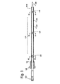
図1は、本出願に従った温度センサ100の第1の実施形態の斜視図を示す。センサ100は、高温を有する流体の温度を感知するのに適している。本出願の状況における高温とは、センサが、−60℃から最大で1000℃を超える温度範囲における流体の物理量温度を測定するために使用されるのに適していることを意味する。図示されるセンサは、特に、処理システムの後のディーゼルにおける排気ガスの流れの温度を測定するために設計される。センサは、自動車および大型の乗り物の用途において存続できる。更に、センサは、処理システムの後にディーゼルにおいて経験される熱衝撃に関し、改善された特徴を有する。
FIG. 1 shows a perspective view of a first embodiment of a
センサ100は、既知のMIケーブル(Mineral Insulated cable、鉱物絶縁ケーブル)102から成り、MIケーブル102は、MIケーブルの感知端102Dに連結される感知素子104を備える。図4〜図6は、MIケーブルの断面を示す。MIケーブルは、外部金属ジャケット102A、外部金属ジャケット102A内に配置される2つまたはそれ以上の導体102B、および、酸化マグネシウム絶縁102Cを含む。MIケーブルの長さは、適用要件(application requirement)に依存する。適用要件次第で、外部金属ジャケットは、インコネルシース、または、例えばステンレス鋼もしくは銅といった任意の他の金属であってもよい。
The
センサ100はさらに、封止フランジ要素106を含む。封止フランジ要素は、用途においてセンサを固定するために取付けナット108と共に使用される。封止フランジ要素106は、例えば溶接によりMIケーブルの外部金属ジャケットに取付けられるリング形状の要素であり得る。リング形状の溶接は、MIケーブルとリング形状の要素との間のハーメチックの封止を形成する。取付けナットを、デバイスの開口においてねじ留めすることにより(その開口を通って感知素子が、流体における温度を感知するため、デバイスのキャビティにおいて位置決めされる)、封止フランジ要素は、センサを備えるデバイスの開口を好ましくは密封して封止するように、開口の封止面に圧締めされる。
The
センサ100はさらに、管状要素110を含む。管状要素は、押出しプロセスにより得られる押出し部分であってよい。管状要素は、外部金属ジャケットに対して外部に位置され、封止フランジ要素106とMIケーブルの感知端102Dとの間でMIケーブル102の少なくとも一部を囲繞する。管状要素は、例えばインコネル、ステンレス鋼または銅といった任意の適切な合金から構成されてよい。管状要素は、外部金属ジャケットの上に適合してMIケーブルの外面と管状要素の内面との間に空間を空けるような内径を有する。管状要素110の近位端110Aは、例えばレーザ溶接によって、封止フランジ要素106に取付けられる。
The
管状要素110は半径方向にクリンプされ、クリンプは、管状要素110およびMIケーブル102の軸と整合するようにされる。このやり方において、管状要素の内面の大部分は、MIケーブルの外面から予め定義された距離にある。この距離は、MIケーブルと管状要素との間に隙間(ギャップ)を形成する。使用中、隙間は、温度が測定される流体で満たされる。より高額な実施形態において、隙間は、測定される流体の高温に耐える任意の適切な可撓性の断熱材で満たされてもよい。前述の距離は、好ましくは、1)隙間における流体を介した伝導と、2)管状要素からMIケーブルまでの、エアギャップを横切る放射と、による熱伝達による結合が、管状要素の直径に対して最適であるように選択される。距離は、対流を防止するのに十分に小さく、且つ、隙間を横切る放射を削減するのに足りるだけ十分に大きいものとすべきである。
The
センサ100はさらに、MIケーブルから可撓性のハーネス112まで電気信号を移行する後方ハウジング114を含む。本出願は、封止フランジ要素と感知素子との間のMIケーブル間の相互作用に焦点を当てる。
The
或る実施形態において、感知素子104は、熱電対接合部(ジャンクション)(N型)(図示せず)によって形成される。熱電対接合部は、MIケーブルの導体を溶接することによって得られる。この実施形態において、センサは、接合部の温度次第で導体における電圧差を出力する機能を有する。接合部は、MIケーブルの外部金属ジャケットに溶接される保護隙間により、感知される流体から保護される。
In some embodiments, the
管状要素110の機能は以下の通りである。センサの環境への熱エネルギーの印加の間、熱は、まず、シースアッセンブリ外面に移動しなければならない。内面の熱は、隙間における媒体を通って伝導するか、流体の場合は隙間間の放射によって伝達するか、または、MIケーブルの外部金属ジャケットとの機械的コンタクトを有するクリンプのエリア全体を伝導し得る。これは、外部ジャケット102とMIケーブル102Bの導体との間の温度勾配の大きさを小さくし、それゆえ、外部ジャケットとMIケーブルの導体の熱膨張の差を小さくする効果を有する。これは、熱サイクルの間に導体によって経験される応力の大きさを小さくし、それゆえ、センサの熱衝撃応答を改善する。
The function of the
排気システムにおける排気ガスの流れの温度が、流れの断面において等しく分散されず、個々の用途に高く依存することを、実験が示した。本出願において、「ホットスポット領域(hot spot region)」という用語は、高い温度変化を備える流れにおける領域を指すのに使用され、こうしたホットスポット領域は、適切な使用期間を保証するために、本書において請求される改善を必要とする。更に、管状要素の設計は、共振に誘発される故障を防止するため、用途の振動特性を考慮に入れることが重要であることを、試験が示した。管状要素の相対的な長さを変更することによって共振周波数は変化し得、それゆえ、振動の大きさが削減され得、製品寿命を改善する結果となる。変動する熱および振動特性の場所を考慮に入れることによって、管状要素の長さは、封止フランジ要素と感知素子との間のMIケーブルの長さより短くてよい。図2は、第1の実施形態の部分的な断面図を概略的に示す。この実施形態において、封止フランジ要素106と感知素子104との間のMIケーブルの一部のみが、管状要素110によって形成される熱シールドによって遮蔽されている。この特定の用途において最も高い温度変化を備えるホットスポットは、参照番号120で示してある。
Experiments have shown that the temperature of the exhaust gas flow in the exhaust system is not equally distributed in the flow cross section and is highly dependent on the individual application. In this application, the term “hot spot region” is used to refer to a region in a flow with a high temperature change, and such hot spot region is used in this document to ensure proper service life. In need of improvement claimed in In addition, tests have shown that the design of the tubular element is important to take into account the vibration characteristics of the application in order to prevent resonance-induced failures. By changing the relative length of the tubular elements, the resonant frequency can be changed, thus the magnitude of vibration can be reduced, resulting in improved product life. By taking into account the location of fluctuating thermal and vibration characteristics, the length of the tubular element may be shorter than the length of the MI cable between the sealing flange element and the sensing element. FIG. 2 schematically shows a partial cross-sectional view of the first embodiment. In this embodiment, only a portion of the MI cable between the sealing
図2は、管状要素110が3つの半径方向にクリンプされた領域130を含むことをさらに示す。2つの左側のクリンプされた領域の断面図が図4に提供され、感知素子に最も近接するクリンプされた領域の断面図が図5に提供される。MIケーブルの周囲の保護管の近位端に2つのクリンプされた領域を有することが、振動に対する、封止要素106と管状要素110との結合の抵抗を改善することを、試験が示した。好ましくは、半径方向にクリンプされた領域は、熱移動を削減するようにホットスポットに存在しない。
FIG. 2 further shows that the
図3は、温度センサの第2の実施形態の部分的な断面図を概略的に示す。この実施形態は、管状要素110が、封止フランジ要素と感知素子との間のMIケーブルの長さに沿って完全に延在している点で、図2における実施形態とは異なる。これは、ホットスポット領域122が、流体と接触したMIケーブルの長さの比較的小さい部分に限定されない場合に必要である。更に、感知される流体に挿入されるMIケーブルの長さが長く、且つ、ホットスポットが幅広の場合、封止要素側に位置される1つまたは2つのクリンプと、感知素子側に位置されるクリンプとの間に1つまたは複数のクリンプされた領域を有することが必要とされる場合がある。例えば、MIケーブルの軸に垂直の流れの速度が速く、クリンプが中間で使用されない場合、管状要素は、隙間幅が全ての場所で同一でないように流れによって変形されてよい。従って、流体から、管状要素および隙間を介した、MIケーブルまでの熱伝達特性は、MIケーブルの周辺で等しくなく、熱膨張が異なることに起因して、MIケーブルは、一方の側で、他方の側よりも早く熱せられて曲がる。追加のクリンプされた領域は、管状要素110の中心軸とMIケーブル102の中心軸の整合を改善する。これが、管状要素とクリンプされていない領域のMIケーブルとの間の予め定義された一定の隙間幅という結果となり、従って、MIケーブルのボディ軸に垂直の熱源の角度方向とは無関係の感知デバイスの熱感度となる。
FIG. 3 schematically shows a partial cross-sectional view of a second embodiment of the temperature sensor. This embodiment differs from the embodiment in FIG. 2 in that the
図4は、クリンプされた領域の第1の実施形態の断面図を概略的に示す。外部金属ジャケット102Aにおいて、2つの導体102Bが、次に限定されないが、酸化マグネシウムなどの絶縁材料102C内に位置される。クリンプされた領域は、8つの幅広の窪み130Aを含む。このクリンプされた領域において、管状要素110の内側の大部分が、MIケーブルの外面に圧締めされる。更に、ほとんど隙間がない。このタイプのクリンプは、管状要素と金属ジャケットとの間に強い機械的な固定を提供するという利点を有し、剛性および振動抵抗を改善する。このタイプのクリンプの欠点は、これらの領域における管状要素からMIケーブルまでの熱伝達が非常に良いこと、すなわち、熱抵抗が非常に低いことである。それゆえ、このタイプのクリンプは、封止フランジ要素に連結される管状要素の端部で使用される。この領域において、ホットスポットの外およびセンサの根元なので、機械的固定が最も重要な特性である。
FIG. 4 schematically shows a cross-sectional view of the first embodiment of the crimped region. In the
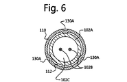
図5は、クリンプされた領域の第2の実施形態の断面図を概略的に示す。この実施形態は、クリンプされた領域が4つの狭い窪み130Aを含むという点で、先の実施形態とは異なる。このクリンプされた領域において、管状要素110の内側の小さな部分が、MIケーブルの外面に圧締めされる。更に、管状要素110とジャケット102Aとの間の空間が隙間を形成する。このタイプのクリンプは、この領域における管状要素からMIケーブルまでの熱伝達が、図4に示されたクリンプされた領域よりもはるかに少ない、すなわち、熱抵抗が高いという利点を有する。このタイプのクリンプされた領域の欠点は、機械的剛性があまり提供されず、また、クリンプされた領域の外側に対して、クリンプされた領域の一方の側の管状要素の相対的な振動に対する抵抗があまり提供されないことである。それゆえ、このタイプのクリンプは、管状要素の遠位端セクション110Bで、必要に応じてホットスポット領域において使用される。図6は、3つの窪みを備えるクリンプされた領域の代替的な実施形態の断面図を概略的に示す。半径方向にクリンプするプロセスの間に3つまたはそれ以上の窪みを生成することにより、MIケーブルおよび管状要素の両方の中心軸を整合するのが容易になる。好ましくは、半径方向にクリンプされた領域の3つまたはそれ以上の窪みは、互いから等しい距離に位置される。
FIG. 5 schematically shows a cross-sectional view of a second embodiment of the crimped region. This embodiment differs from the previous embodiment in that the crimped region includes four
図7は、図2における第1の実施形態の断面図を詳細に概略的に示す。この図は、管状要素110と封止フランジ要素106との間の連結を示す。この実施形態において、封止フランジ要素は、MIケーブルの金属ジャケット102Aにレーザ溶接によって取付けられる封止リングである。管状要素の端部110Aは、封止リングにレーザ溶接される。更に、2つの半径方向にクリンプされた領域の凹み130Aが見える。この実施形態において、クリンプされた領域は、管状要素に位置される。
FIG. 7 schematically shows in detail a cross-sectional view of the first embodiment in FIG. This figure shows the connection between the
図8は、封止要素の代替的な実施形態を概略的に示す。この実施形態において、封止フランジ要素は、一片の金属から作られ、リングセクション106Aと管セクション106Bとを含む。管状要素の端部110Aは、管セクション106Bの遠位端106B1に取付けられる。更に、管セクション106Bは、2つの場所で半径方向にクリンプされる。この実施形態において、封止フランジ要素106と管状要素110との間の溶接された接合は、振動に起因して応力に対してあまり感度が高くないことを、試験が示した。管セクション106Bは、その遠位端に1つのクリンプされた領域を含み、管状要素110の近位端は、クリンプされた領域を含むことが、さらに可能であり得る。この実施形態において、封止フランジ要素間の接合は、前述の2つのクリンプされた領域の間にある。
FIG. 8 schematically shows an alternative embodiment of the sealing element. In this embodiment, the sealing flange element is made from a piece of metal and includes a
図9は、封止フランジ要素106と管状要素110との間の接続の実施形態を示す。この実施形態において、封止フランジ要素は、リングセクション106Aと管セクション106Bとを含む1つの片(一体)である。整合特徴106B2が、管状要素110に面する封止フランジ要素106の側に提供される。整合特徴106B2は、フランジ要素106と同軸の管セクション106Bの遠位端106B1にある三角形状の突出である。三角形の突出は、管状要素110の端部110Aの開口に適合する。本実施形態において、管セクション106Bおよび管状要素110の外径は類似している。同様に、管セクション106Bの内径は、管状要素110の内径より小さい。三角形の突出106B2の外径は、管状要素110の内径と一致する。管セクション106Bの遠位端106B1に対して管状要素を位置決めする場合、三角形の突出は、封止要素106および管状要素110の中心軸を整合する。その後、円形溶接により管状要素110は封止要素106に取付けられる。
FIG. 9 shows an embodiment of the connection between the sealing
封止フランジ要素の貫通孔の直径がMIケーブルの直径に対応する場合、三角形の突出106B2は、好ましくはMIケーブル(図9に図示せず)と管状要素110との間の所望の隙間幅に等しい幅を有する。このやり方において、管状要素110の近位端110Aに近接する管状要素の半径方向のクリンプは必要でない。
If the diameter of the through hole of the sealing flange element corresponds to the diameter of the MI cable, the triangular protrusion 106B2 preferably has a desired gap width between the MI cable (not shown in FIG. 9) and the
フランジ要素106の貫通孔と管状要素110の直径が類似している場合、管状要素110の近位端110Aは三角形の突出106B2を受けるための環状の窪みを含むことに留意すべきである。更に、管セクション106Bの遠位端に半径方向にクリンプされた領域は、管セクションおよびMIケーブル102の中心軸を整合する。従って、三角形の突出106B2は、管状要素110の少なくとも近位端部分の中心軸と整合する。
It should be noted that when the through-hole of the
上述の実施形態は、以下の動作を含む方法によって組立てられてよい。外部金属ジャケットを備える鉱物絶縁ケーブルと、外部金属ジャケットにおいて配置される導体と、酸化マグネシウム絶縁とを含む構成要素を提供する。任意選択で、物理量を感知するために構成される感知素子は、鉱物絶縁ケーブルの感知端に既に連結される。封止フランジ要素を提供する。円形溶接プロセスにより、封止フランジ要素を鉱物絶縁ケーブルに取付ける。その後、管状要素が提供される。封止フランジ要素と感知端との間の鉱物絶縁ケーブルの少なくとも一部が、管状要素において位置決めされ、および、管状要素によって囲繞されるように、遠位端は、管状要素において、および/または、管状要素を通って挿入される。管状要素の内面の大部分が、鉱物絶縁ケーブルの外面から予め定義された距離にあり、鉱物絶縁ケーブルと管状要素との間に隙間を形成するように、管状要素が位置決めされる。 The embodiments described above may be assembled by a method that includes the following operations. A component is provided that includes a mineral insulated cable with an outer metal jacket, a conductor disposed in the outer metal jacket, and magnesium oxide insulation. Optionally, a sensing element configured to sense a physical quantity is already coupled to the sensing end of the mineral insulated cable. A sealing flange element is provided. The sealing flange element is attached to the mineral insulated cable by a circular welding process. Thereafter, a tubular element is provided. The distal end is in the tubular element and / or so that at least a portion of the mineral insulated cable between the sealing flange element and the sensing end is positioned in and surrounded by the tubular element Inserted through the tubular element. The tubular element is positioned such that the majority of the inner surface of the tubular element is at a predefined distance from the outer surface of the mineral insulated cable and forms a gap between the mineral insulated cable and the tubular element.
半径方向にクリンプするプロセスにより、3つまたはそれ以上窪みを備えるクリンプされた領域が管状要素に形成されてよい。窪みの深さは、好ましくは、隙間の予め定義された幅よりもわずかに広い。このやり方において、管状要素のボディ軸は、MIケーブルのボディ軸と整合され、他方、金属ジャケットは最小限に変形され、管状要素は、型締力により軸方向にMIケーブルに取付けられる。このやり方において、感知デバイスの実施形態を有することが可能となり、管状要素は、管状要素の軸方向の動きを防止するため、1つの端部で封止フランジ要素に取付けられない。この実施形態において、管状要素は、管状要素とMIケーブルとの間に軸方向に一定の隙間幅を得るために、少なくとも2つのクリンプされた領域、すなわち両方の端部を含むものでなければならない。感知デバイスの用途は、この実施形態が適切かどうかを判定する。 By the process of crimping in the radial direction, a crimped region comprising three or more depressions may be formed in the tubular element. The depth of the depression is preferably slightly wider than the predefined width of the gap. In this manner, the body axis of the tubular element is aligned with the body axis of the MI cable, while the metal jacket is minimally deformed and the tubular element is attached to the MI cable axially by a clamping force. In this manner, it is possible to have an embodiment of the sensing device and the tubular element is not attached to the sealing flange element at one end to prevent axial movement of the tubular element. In this embodiment, the tubular element must include at least two crimped areas, i.e. both ends, in order to obtain an axially constant gap width between the tubular element and the MI cable. . The application of the sensing device determines whether this embodiment is appropriate.
図に示された実施形態を得るため、方法はさらに、管状要素の近位端を封止フランジ要素に取付けることを含む。 To obtain the embodiment shown in the figure, the method further includes attaching the proximal end of the tubular element to the sealing flange element.
本出願の利点は、熱衝撃の間の熱電対パフォーマンスの根本的な改善、熱サイクルの間の製品寿命の向上、および、所与の流体温度のためのより低い全体の導体温度を含む。本出願は、プローブの長さが長く、または拡張された温度の動作温度感知範囲を備えるセンサを説明し、センサは、封止フランジ要素と感知素子との間でMIケーブルを使用する。これらのセンサは、長期間にわたり自動車環境に耐える。 Advantages of this application include a fundamental improvement in thermocouple performance during thermal shock, an increase in product life during thermal cycling, and a lower overall conductor temperature for a given fluid temperature. This application describes a sensor with a long probe length or an extended temperature operating temperature sensing range, where the sensor uses an MI cable between the sealing flange element and the sensing element. These sensors withstand the automotive environment for extended periods of time.
説明された実施形態の全てが、温度感知素子としてN型の高温熱電対を含むことに留意すべきである。所望の利点を得るために、N型の高温熱電対は、広範囲の急速に変化する温度を有する流体の物理的特性を感知するための、任意の他の感知素子によって交換できることがあきらかであろう。他の感知素子の実施例は、他のタイプの高温熱電対、PTCまたはNTCサーミスタ、および酸素感知素子(またはラムダセンサ)に限定されない。 It should be noted that all of the described embodiments include an N-type high temperature thermocouple as the temperature sensing element. It will be apparent that N-type high temperature thermocouples can be replaced by any other sensing element to sense the physical properties of a fluid having a wide range of rapidly changing temperatures to obtain the desired benefits. . Other sensing element embodiments are not limited to other types of high temperature thermocouples, PTC or NTC thermistors, and oxygen sensing elements (or lambda sensors).
本発明がいくつかの実施形態によって説明されたが、それらの代替、修正、置換、または、均等物が、明細書を読み、図面を検討することから当業者にとって明らかであることが意図される。本発明は、説明された実施形態に限定されない。添付の特許請求の範囲の範囲から逸脱することなく、変更が成されてよい。 While the invention has been described in terms of several embodiments, it is intended that alternatives, modifications, substitutions or equivalents thereof will be apparent to those skilled in the art from reading the specification and reviewing the drawings. . The invention is not limited to the described embodiments. Changes may be made without departing from the scope of the appended claims.
Claims (16)
外部金属ジャケット、前記外部金属ジャケットにおいて配置される導体、および、酸化マグネシウム絶縁を備える鉱物絶縁ケーブルと、
前記物理量を感知するために構成され、前記鉱物絶縁ケーブルの感知端に連結される感知素子と、
前記鉱物絶縁ケーブルの前記外部金属ジャケットに連結される封止フランジ要素と、
前記封止フランジ要素と前記鉱物絶縁ケーブルの前記感知端との間の前記鉱物絶縁ケーブルの少なくとも一部を囲繞する管状要素であって、前記管状要素の内面の大部分が、前記鉱物絶縁ケーブルの外面から予め定義された距離にあり、前記鉱物絶縁ケーブルと前記管状要素との間に隙間を形成する、前記管状要素と
を含む、感知デバイス。 A sensing device for sensing a physical quantity of a fluid having a high temperature,
An outer metal jacket, a conductor disposed in the outer metal jacket, and a mineral insulated cable comprising magnesium oxide insulation;
A sensing element configured to sense the physical quantity and coupled to a sensing end of the mineral insulated cable;
A sealing flange element connected to the outer metal jacket of the mineral insulated cable;
A tubular element surrounding at least a portion of the mineral-insulated cable between the sealing flange element and the sensing end of the mineral-insulated cable, wherein a majority of the inner surface of the tubular element is A sensing device comprising the tubular element at a predefined distance from an outer surface and forming a gap between the mineral-insulated cable and the tubular element.
外部金属ジャケット、前記外部金属ジャケットにおいて配置される導体、および、酸化マグネシウム絶縁を備える鉱物絶縁ケーブルと、前記物理量を感知するために構成され、前記鉱物絶縁ケーブルの感知端に連結される感知素子とを含む構成要素を提供するステップと、
封止フランジ要素を提供するステップと、
前記封止フランジ要素を前記鉱物絶縁ケーブルに取付けるステップと、
管状要素を提供するステップと、
前記管状要素の内面の大部分が、前記鉱物絶縁ケーブルの外面から予め定義された距離にあり、鉱物絶縁ケーブルと前記管状要素との間に隙間を形成するように、前記管状要素において、前記封止フランジ要素と前記感知素子との間に前記鉱物絶縁ケーブルの少なくとも一部を位置決めするステップと
を含む、方法。 A method of assembling a sensing device for sensing a physical quantity of a fluid having a high temperature, the method comprising:
An external metal jacket, a conductor disposed in the external metal jacket, and a mineral insulated cable comprising magnesium oxide insulation; and a sensing element configured to sense the physical quantity and coupled to a sensing end of the mineral insulated cable; Providing a component comprising:
Providing a sealing flange element;
Attaching the sealing flange element to the mineral insulated cable;
Providing a tubular element;
In the tubular element, the sealing is such that a major portion of the inner surface of the tubular element is at a predefined distance from the outer surface of the mineral-insulated cable and forms a gap between the mineral-insulated cable and the tubular element. Positioning at least a portion of the mineral insulated cable between a stop flange element and the sensing element.
外部金属ジャケット、前記外部金属ジャケットにおいて配置される導体、および、絶縁体を含むケーブルであって、前記ケーブルが感知端を有する、前記ケーブルと、
前記物理量を感知するために構成され、前記感知端に連結される感知素子と、
前記鉱物絶縁ケーブルの前記外部金属ジャケットに連結される封止フランジと、
前記封止フランジと前記感知端との間の前記ケーブルの少なくとも一部を囲繞する管状要素であって、前記ケーブルと前記管状要素との間の隙間を形成し、前記隙間が測定のための流体で満たされる、前記管状要素と
を含む、デバイス。 A device for sensing a physical quantity of a fluid having a high temperature, the device comprising:
A cable comprising an outer metal jacket, a conductor disposed in the outer metal jacket, and an insulator, wherein the cable has a sensing end; and
A sensing element configured to sense the physical quantity and coupled to the sensing end;
A sealing flange connected to the outer metal jacket of the mineral insulated cable;
A tubular element surrounding at least a portion of the cable between the sealing flange and the sensing end, forming a gap between the cable and the tubular element, the gap being a fluid for measurement And a tubular element filled with the device.
Applications Claiming Priority (2)
| Application Number | Priority Date | Filing Date | Title |
|---|---|---|---|
| US15/385,376 US10428716B2 (en) | 2016-12-20 | 2016-12-20 | High-temperature exhaust sensor |
| US15/385,376 | 2016-12-20 |
Publications (2)
| Publication Number | Publication Date |
|---|---|
| JP2018100965A true JP2018100965A (en) | 2018-06-28 |
| JP2018100965A5 JP2018100965A5 (en) | 2021-02-04 |
Family
ID=57909491
Family Applications (1)
| Application Number | Title | Priority Date | Filing Date |
|---|---|---|---|
| JP2017241568A Pending JP2018100965A (en) | 2016-12-20 | 2017-12-18 | High-temperature exhaust sensor |
Country Status (5)
| Country | Link |
|---|---|
| US (1) | US10428716B2 (en) |
| EP (1) | EP3339825B1 (en) |
| JP (1) | JP2018100965A (en) |
| KR (1) | KR20180071966A (en) |
| CN (1) | CN108204863A (en) |
Families Citing this family (4)
| Publication number | Priority date | Publication date | Assignee | Title |
|---|---|---|---|---|
| WO2018120111A1 (en) * | 2016-12-30 | 2018-07-05 | Rosemount Inc. | Adjustable spring loaded adapter for temperature sensor |
| US10753807B2 (en) * | 2018-01-19 | 2020-08-25 | Te Wire & Cable Llc | Thermocouple termination/closure and method |
| FR3088424B1 (en) * | 2018-11-08 | 2021-09-24 | Sc2N Sa | TEMPERATURE SENSOR WITH ANTI-ROTATION STOP |
| CN113916393A (en) * | 2021-10-22 | 2022-01-11 | 中国原子能科学研究院 | Thermocouple protective tube and fast reactor intermediate heat exchanger |
Citations (4)
| Publication number | Priority date | Publication date | Assignee | Title |
|---|---|---|---|---|
| JPH05248963A (en) * | 1991-12-10 | 1993-09-28 | Schlumberger Ind Ltd | Thermocouple |
| JP2006078305A (en) * | 2004-09-09 | 2006-03-23 | Mitsubishi Heavy Ind Ltd | Turbine temperature measuring device and temperature measuring device |
| JP2009115478A (en) * | 2007-11-02 | 2009-05-28 | Mitsubishi Heavy Ind Ltd | Quick-response thermocouple for high-speed fluid |
| JP2009294203A (en) * | 2008-05-09 | 2009-12-17 | Ngk Spark Plug Co Ltd | Temperature sensor |
Family Cites Families (174)
| Publication number | Priority date | Publication date | Assignee | Title |
|---|---|---|---|---|
| US2820839A (en) * | 1953-07-23 | 1958-01-21 | Gen Motors Corp | Thermocouple |
| US3691842A (en) | 1970-09-08 | 1972-09-19 | Beckman Instruments Inc | Differential pressure transducer |
| GB1461574A (en) | 1973-03-26 | 1977-01-13 | Smiths Industries Ltd | Temperature-sensing probes |
| US4080027A (en) | 1976-07-30 | 1978-03-21 | Gte Sylvania Incorporated | Electrical contact and connector |
| US4131088A (en) | 1976-11-08 | 1978-12-26 | The Bendix Corporation | Multiple function pressure sensor |
| US4274125A (en) | 1979-01-23 | 1981-06-16 | The Bendix Corporation | Temperature compensated capacitance pressure transducer |
| US4347745A (en) | 1980-12-22 | 1982-09-07 | Bourns Instruments, Inc. | Pressure measuring apparatus |
| US4453835A (en) * | 1982-05-03 | 1984-06-12 | Clawson Burrell E | Temperature sensor |
| US4499330A (en) * | 1983-12-23 | 1985-02-12 | General Electric Company | Anti-vibration support for thermocouple tip |
| US4984461A (en) | 1984-03-14 | 1991-01-15 | Alco Standard Corporation | Fluid flow sensor |
| US4716492A (en) | 1986-05-05 | 1987-12-29 | Texas Instruments Incorporated | Pressure sensor with improved capacitive pressure transducer |
| DE3823449A1 (en) | 1988-07-11 | 1990-01-18 | Bosch Gmbh Robert | MEASURING DEVICE FOR DETECTING PRESSURE AND TEMPERATURE |
| DE3832568A1 (en) | 1988-09-24 | 1990-03-29 | Philips Patentverwaltung | CIRCUIT ARRANGEMENT FOR TEMPERATURE COMPENSATION OF CAPACITIVE PRESSURE AND DIFFERENTIAL PRESSURE SENSORS |
| US4875135A (en) | 1988-12-02 | 1989-10-17 | Texas Instruments Incorporated | Pressure sensor |
| US4955380A (en) | 1988-12-15 | 1990-09-11 | Massachusetts Institute Of Technology | Flexible measurement probes |
| US5259248A (en) | 1990-03-19 | 1993-11-09 | Hitachi Ltd. | Integrated multisensor and static and differential pressure transmitter and plant system using the integrated multisensor |
| US5231301A (en) | 1991-10-02 | 1993-07-27 | Lucas Novasensor | Semiconductor sensor with piezoresistors and improved electrostatic structures |
| US5193912A (en) | 1991-11-18 | 1993-03-16 | Saunders Roger I | Probe for sensing and measuring temperature |
| US5189591A (en) | 1992-06-12 | 1993-02-23 | Allied-Signal Inc. | Aluminosilicate glass pressure transducer |
| JP2546255Y2 (en) | 1992-07-08 | 1997-08-27 | 矢崎総業株式会社 | Female terminal fitting |
| DE69405435T2 (en) | 1993-03-16 | 1998-01-22 | Hewlett Packard Co | Method and device for the production of electrically interconnected circuits |
| EP0616394A1 (en) | 1993-03-16 | 1994-09-21 | Hewlett-Packard Company | Method and system for producing electrically interconnected circuits |
| US5308249A (en) | 1993-06-16 | 1994-05-03 | The Whitaker Corporation | Backplane connector utilizing flexible film circuitry |
| US5606513A (en) | 1993-09-20 | 1997-02-25 | Rosemount Inc. | Transmitter having input for receiving a process variable from a remote sensor |
| US5443394A (en) | 1994-05-04 | 1995-08-22 | The Whitaker Corporation | Card edge connector having positive lock and extractor |
| JPH08178778A (en) | 1994-12-27 | 1996-07-12 | Mitsubishi Electric Corp | Semiconductor pressure detector |
| US5676559A (en) | 1995-07-06 | 1997-10-14 | The Whitaker Corporation | Zero insertion force (ZIF) electrical connector |
| DE19600822A1 (en) * | 1996-01-11 | 1997-07-17 | Basf Ag | Temperature measurement probe |
| US5800186A (en) | 1997-03-13 | 1998-09-01 | Framatome Connectors Usa, Inc. | Printed circuit board assembly |
| JP3379747B2 (en) | 1997-05-20 | 2003-02-24 | 矢崎総業株式会社 | Low insertion force terminal |
| JP3404257B2 (en) | 1997-07-11 | 2003-05-06 | 三菱電機株式会社 | Pressure sensor device |
| US5974893A (en) | 1997-07-24 | 1999-11-02 | Texas Instruments Incorporated | Combined pressure responsive transducer and temperature sensor apparatus |
| FR2775075B1 (en) | 1998-02-18 | 2000-05-05 | Theobald Sa A | DIFFERENTIAL PRESSURE SENSOR |
| US6412977B1 (en) | 1998-04-14 | 2002-07-02 | The Goodyear Tire & Rubber Company | Method for measuring temperature with an integrated circuit device |
| US6308694B1 (en) | 1999-01-11 | 2001-10-30 | Ford Global Technologies, Inc. | Flow measurement and control |
| JP4409114B2 (en) | 1999-03-12 | 2010-02-03 | 日本発條株式会社 | Conductive contact assembly |
| JP2001041838A (en) | 1999-08-03 | 2001-02-16 | Yamatake Corp | Pressure sensor and its manufacture |
| US6473711B1 (en) | 1999-08-13 | 2002-10-29 | Rosemount Inc. | Interchangeable differential, absolute and gage type of pressure transmitter |
| JP2001093634A (en) | 1999-09-21 | 2001-04-06 | Kato Spring Works Co Ltd | Socket for semiconductor package |
| US6313523B1 (en) | 1999-10-28 | 2001-11-06 | Hewlett-Packard Company | IC die power connection using canted coil spring |
| US6341962B1 (en) | 1999-10-29 | 2002-01-29 | Aries Electronics, Inc. | Solderless grid array connector |
| JP3619413B2 (en) | 2000-01-18 | 2005-02-09 | 株式会社エンプラス | Socket for electrical parts |
| US20020029639A1 (en) | 2000-01-19 | 2002-03-14 | Measurement Specialities, Inc. | Isolation technique for pressure sensing structure |
| DE10031124C2 (en) | 2000-06-30 | 2002-05-16 | Heraeus Electro Nite Int | Sensor for temperature measurement of a fluid |
| DE10031120A1 (en) | 2000-06-30 | 2002-01-17 | Grieshaber Vega Kg | Diaphragm Seals |
| US6363922B1 (en) | 2000-10-11 | 2002-04-02 | Detroit Diesel Corp | Exhaust gas recirculation pressure differential sensor error compensation |
| US6625029B2 (en) | 2000-11-06 | 2003-09-23 | Skg Italiana Spa | Sensor unit |
| JP2002170617A (en) | 2000-12-04 | 2002-06-14 | Yokowo Co Ltd | Coil spring connector |
| US6588931B2 (en) | 2000-12-07 | 2003-07-08 | Delphi Technologies, Inc. | Temperature sensor with flexible circuit substrate |
| US6668632B2 (en) | 2001-03-05 | 2003-12-30 | Delphi Technologies, Inc. | Spark apparatus with pressure signal response amplification |
| JP3788363B2 (en) | 2001-03-23 | 2006-06-21 | 株式会社デンソー | Temperature sensor |
| JP4721582B2 (en) | 2001-09-14 | 2011-07-13 | 株式会社センサータ・テクノロジーズジャパン | socket |
| JP2003100375A (en) | 2001-09-26 | 2003-04-04 | Yokowo Co Ltd | Spring connector |
| JP2003168532A (en) | 2001-11-29 | 2003-06-13 | Texas Instr Japan Ltd | Semiconductor device socket and installation method of semiconductor device on socket |
| JP4138305B2 (en) | 2001-12-12 | 2008-08-27 | 株式会社エンプラス | Socket for electrical parts |
| JP2003234203A (en) | 2002-02-07 | 2003-08-22 | Denso Corp | Method of manufacturing temperature sensor |
| US6701790B2 (en) | 2002-06-13 | 2004-03-09 | Mykrolis Corporation | Temperature regulator for use with a pressure sensing device |
| US6952042B2 (en) | 2002-06-17 | 2005-10-04 | Honeywell International, Inc. | Microelectromechanical device with integrated conductive shield |
| US6857776B2 (en) * | 2002-12-12 | 2005-02-22 | Ametek, Inc. | Connectorized high-temperature thermocouple |
| FI115109B (en) | 2003-01-22 | 2005-02-28 | Nokia Corp | An authentication arrangement and a mobile station comprising an authentication arrangement |
| JP3942176B2 (en) | 2003-03-17 | 2007-07-11 | 日本特殊陶業株式会社 | Glow plug with combustion pressure detection function and manufacturing method thereof |
| JP4041018B2 (en) | 2003-06-25 | 2008-01-30 | Tdk株式会社 | Temperature sensor |
| US6776668B1 (en) | 2003-08-01 | 2004-08-17 | Tyco Electronics Corporation | Low profile coaxial board-to-board connector |
| US7938783B2 (en) | 2003-08-19 | 2011-05-10 | Advanced Monitors Corporation | Medical body core thermometer |
| DE10343521A1 (en) | 2003-09-19 | 2005-04-21 | Beru Ag | Pressure measuring glow plug for a diesel engine |
| US6909975B2 (en) | 2003-11-24 | 2005-06-21 | Mks Instruments, Inc. | Integrated absolute and differential pressure transducer |
| JP2005156307A (en) | 2003-11-25 | 2005-06-16 | Denso Corp | Pressure sensor |
| US6948372B2 (en) | 2004-01-08 | 2005-09-27 | Delphi Technologies, Inc. | Method of connection to a spark plug pressure sensor |
| CN2679408Y (en) * | 2004-02-24 | 2005-02-16 | 吴村木 | Tube connecting piece |
| US7021954B2 (en) | 2004-04-16 | 2006-04-04 | Hon Hai Precision Ind. Co., Ltd. | Test connector with metallic stiffener |
| DE102004021041A1 (en) | 2004-04-29 | 2005-11-24 | Robert Bosch Gmbh | Combined absolute pressure and relative pressure sensor |
| JP2005327628A (en) | 2004-05-14 | 2005-11-24 | Three M Innovative Properties Co | Ic socket |
| US7077008B2 (en) | 2004-07-02 | 2006-07-18 | Honeywell International Inc. | Differential pressure measurement using backside sensing and a single ASIC |
| US7073375B2 (en) | 2004-07-02 | 2006-07-11 | Honeywell International Inc. | Exhaust back pressure sensor using absolute micromachined pressure sense die |
| EP1637806B1 (en) | 2004-09-15 | 2012-02-01 | Beru AG | Glow plug with pressure sensor for a diesel engine |
| DE102004048367B4 (en) | 2004-10-01 | 2010-10-28 | Endress + Hauser Gmbh + Co. Kg | Method for filling a pressure measuring transducer |
| US7302855B2 (en) | 2004-10-28 | 2007-12-04 | Denso Corporation | Pressure detection device |
| JP4742593B2 (en) | 2005-01-19 | 2011-08-10 | 株式会社デンソー | Manufacturing method of pressure detecting device |
| US7000478B1 (en) | 2005-01-31 | 2006-02-21 | Texas Instruments Incorporated | Combined pressure and temperature transducer |
| US7884432B2 (en) | 2005-03-22 | 2011-02-08 | Ametek, Inc. | Apparatus and methods for shielding integrated circuitry |
| JP2006307834A (en) | 2005-03-31 | 2006-11-09 | Ngk Spark Plug Co Ltd | Combustion pressure sensor and glow plug including the same |
| FR2884298B1 (en) | 2005-04-12 | 2007-08-10 | Siemens Vdo Automotive Sas | PRE-HEATING CUP WITH INTEGRATED PRESSURE SENSOR |
| JP2006324326A (en) | 2005-05-17 | 2006-11-30 | Elpida Memory Inc | Semiconductor device |
| JP4421511B2 (en) | 2005-05-30 | 2010-02-24 | 三菱電機株式会社 | Semiconductor pressure sensor |
| DE102006022620B4 (en) | 2005-08-19 | 2014-05-22 | Otto Egelhof Gmbh & Co. Kg | temperature sensor |
| US7316507B2 (en) | 2005-11-03 | 2008-01-08 | Covidien Ag | Electronic thermometer with flex circuit location |
| JP2007132697A (en) | 2005-11-08 | 2007-05-31 | Denso Corp | Pressure sensor |
| JP4765871B2 (en) | 2005-11-09 | 2011-09-07 | 株式会社デンソー | Temperature sensor |
| US7467891B2 (en) | 2005-11-29 | 2008-12-23 | Sensata Technologies, Inc. | Sensor arrangement for measuring a pressure and a temperature in a fluid |
| DE102005060651A1 (en) | 2005-12-19 | 2007-06-28 | Robert Bosch Gmbh | Combined pressure and temperature sensor |
| TWI286383B (en) | 2005-12-23 | 2007-09-01 | Delta Electronics Inc | Semiconductor piezoresistive sensor and operation method thereof |
| US20070193362A1 (en) | 2006-02-06 | 2007-08-23 | Ferguson Stephen K | Fiber optic strain gage |
| US7675409B2 (en) | 2006-02-28 | 2010-03-09 | Paksense, Inc. | Environmental sensing |
| EA014109B1 (en) | 2006-04-03 | 2010-10-29 | Эксонмобил Апстрим Рисерч Компани | Wellbore method and apparatus for sand and inflow control during well operations |
| JP4867437B2 (en) | 2006-04-05 | 2012-02-01 | 株式会社デンソー | Temperature sensor |
| US7597668B2 (en) | 2006-05-31 | 2009-10-06 | Medisim Ltd. | Non-invasive temperature measurement |
| JP2008064529A (en) | 2006-09-06 | 2008-03-21 | Denso Corp | Pressure sensitive sensor |
| DE102006043324A1 (en) | 2006-09-15 | 2008-03-27 | Robert Bosch Gmbh | Plug-in sensor for combined pressure and temperature measurement |
| WO2008041607A1 (en) | 2006-10-02 | 2008-04-10 | Panasonic Electric Works Co., Ltd. | Pressure sensor |
| JP4867559B2 (en) | 2006-10-04 | 2012-02-01 | 株式会社デンソー | Pressure sensor and pressure sensor mounting structure |
| DE102006050451A1 (en) | 2006-10-20 | 2008-04-24 | Endress + Hauser Gmbh + Co. Kg | pressure monitor |
| US7814893B2 (en) | 2006-11-17 | 2010-10-19 | Continental Automotive Canada, Inc. | Exhaust gas recirculation system module with integral vacuum |
| US20080219319A1 (en) | 2007-01-05 | 2008-09-11 | Jay Buckalew | Biological parameter monitoring system and method therefor |
| DE102007010403B4 (en) | 2007-03-01 | 2016-02-11 | Heraeus Sensor Technology Gmbh | Temperature sensor and its use in a turbocharger overheating fuse |
| JP4858293B2 (en) | 2007-05-08 | 2012-01-18 | 住友電装株式会社 | Female terminal bracket |
| JP4854612B2 (en) | 2007-07-09 | 2012-01-18 | センサータ テクノロジーズ マサチューセッツ インコーポレーテッド | Socket adapter |
| US7651366B2 (en) | 2007-07-16 | 2010-01-26 | Tyco Electronics Corporation | Electrical connector assembly with shorting contacts |
| JP2009074905A (en) | 2007-09-20 | 2009-04-09 | Denso Corp | Temperature sensor device for engine |
| JP2009097926A (en) | 2007-10-15 | 2009-05-07 | Denso Corp | Pressure sensor and its mounting structure |
| JP4868413B2 (en) | 2007-12-04 | 2012-02-01 | センサータ テクノロジーズ インコーポレーテッド | socket |
| US7762140B2 (en) | 2008-01-10 | 2010-07-27 | Sensata Technologies, Inc. | Combined fluid pressure and temperature sensor apparatus |
| US20090194831A1 (en) | 2008-02-01 | 2009-08-06 | Custom Sensors & Technologies, Inc. | Integrated cavity in pcb pressure sensor |
| US7578194B1 (en) | 2008-02-11 | 2009-08-25 | Sensata Technologies, Inc. | Differential fluid pressure measurement apparatus |
| US7743662B2 (en) | 2008-02-14 | 2010-06-29 | Kulite Semiconductor Products, Inc. | Low differential pressure transducer |
| US8764464B2 (en) | 2008-02-29 | 2014-07-01 | Fci Americas Technology Llc | Cross talk reduction for high speed electrical connectors |
| TWM344664U (en) | 2008-04-07 | 2008-11-11 | Hon Hai Prec Ind Co Ltd | Electrical contact |
| US7591186B1 (en) | 2008-05-15 | 2009-09-22 | Honeywell International Inc. | Conductive seals and method for fabricating the same |
| US7695285B2 (en) | 2008-05-29 | 2010-04-13 | Yokowo Co., Ltd. | Spring connector and connector |
| ITTO20080484A1 (en) | 2008-06-19 | 2009-12-20 | Eltek Spa | PRESSURE SENSOR DEVICE |
| EP2138820B1 (en) | 2008-06-25 | 2016-09-21 | Sensata Technologies, Inc. | A piezoresistive pressure-measuring plug for a combustion engine |
| DE102008002682B4 (en) | 2008-06-26 | 2020-01-30 | Robert Bosch Gmbh | Device for detecting the pressure and the temperature in an intake manifold of an internal combustion engine |
| CH699078A1 (en) | 2008-07-02 | 2010-01-15 | Kistler Holding Ag | Spark plug in basic structure with pressure sensor. |
| US7878074B1 (en) | 2008-07-17 | 2011-02-01 | Strain Measurement Devices, Inc. | Eccentric load sensing device used to sense differential pressures |
| JP5166176B2 (en) | 2008-09-04 | 2013-03-21 | スリーエム イノベイティブ プロパティズ カンパニー | Socket for electronic devices |
| JP5227729B2 (en) | 2008-10-07 | 2013-07-03 | アズビル株式会社 | Pressure sensor |
| JP5197297B2 (en) | 2008-10-17 | 2013-05-15 | スリーエム イノベイティブ プロパティズ カンパニー | IC socket |
| JP5291585B2 (en) | 2008-11-07 | 2013-09-18 | 株式会社日本マイクロニクス | Contactor and electrical connection device |
| JP2010118275A (en) | 2008-11-13 | 2010-05-27 | Yamaichi Electronics Co Ltd | Socket for semiconductor device |
| WO2010056935A1 (en) | 2008-11-14 | 2010-05-20 | Molex Incorporated | Resonance modifying connector |
| DE102009026402B4 (en) * | 2008-11-19 | 2023-11-02 | Endress + Hauser Wetzer Gmbh + Co. Kg | Device for determining and/or monitoring a process variable |
| US8217309B2 (en) | 2008-12-15 | 2012-07-10 | Federal-Mogul Italy Srl. | Glow plug with pressure sensing canister |
| JP5187188B2 (en) | 2008-12-26 | 2013-04-24 | 富士通株式会社 | Method for installing semiconductor integrated circuit package and method for manufacturing electronic component |
| US7976326B2 (en) | 2008-12-31 | 2011-07-12 | Fci Americas Technology Llc | Gender-neutral electrical connector |
| EP2406606B1 (en) * | 2009-03-13 | 2019-07-31 | Stoneridge, Inc. | Sensor lead sealing and strain relief |
| JP2010256187A (en) | 2009-04-24 | 2010-11-11 | Panasonic Electric Works Co Ltd | Pressure sensor |
| US8215176B2 (en) | 2009-05-27 | 2012-07-10 | Continental Automotive Systems, Inc. | Pressure sensor for harsh media sensing and flexible packaging |
| US20110019714A1 (en) | 2009-07-24 | 2011-01-27 | Perry Loren R | Overmolded temperature sensor and method for fabricating a temperature sensor |
| US8545096B2 (en) * | 2009-08-06 | 2013-10-01 | Ge Infrastructure Sensing, Inc. | Thermal sensor device and method of assembly |
| US8263879B2 (en) | 2009-11-06 | 2012-09-11 | International Business Machines Corporation | Axiocentric scrubbing land grid array contacts and methods for fabrication |
| KR20130009956A (en) | 2010-02-01 | 2013-01-24 | 스토너릿지 인코포레이티드 | Exhaust gas temperature sensor including strain relief and/or anti-vibration sleeve |
| KR101673520B1 (en) | 2010-03-04 | 2016-11-08 | 삼성전자 주식회사 | Semiconductor module, socket for semiconductor module and connection structure thereof |
| CN201667414U (en) | 2010-04-07 | 2010-12-08 | 富士康(昆山)电脑接插件有限公司 | Electric connector |
| JP2011220927A (en) | 2010-04-13 | 2011-11-04 | Yamatake Corp | Pressure sensor |
| US8129624B2 (en) | 2010-05-27 | 2012-03-06 | Sensata Technologies, Inc. | Pressure sensor |
| US8758067B2 (en) | 2010-06-03 | 2014-06-24 | Hsio Technologies, Llc | Selective metalization of electrical connector or socket housing |
| US8234927B2 (en) | 2010-06-08 | 2012-08-07 | Rosemount Inc. | Differential pressure sensor with line pressure measurement |
| US8132464B2 (en) | 2010-07-12 | 2012-03-13 | Rosemount Inc. | Differential pressure transmitter with complimentary dual absolute pressure sensors |
| CN102072782B (en) * | 2010-08-20 | 2012-08-08 | 丁锡端 | Novel non-welding thermoelectric couple (resistor) |
| DE112011104403T5 (en) | 2010-12-15 | 2013-09-19 | Panasonic Corporation | Semiconductor pressure sensor |
| US8171800B1 (en) | 2011-01-25 | 2012-05-08 | Continental Automotive Systems, Inc. | Differential pressure sensor using dual backside absolute pressure sensing |
| US8523432B2 (en) | 2011-02-04 | 2013-09-03 | Honeywell International Inc. | Thermally isolated temperature sensor |
| WO2012112222A1 (en) | 2011-02-16 | 2012-08-23 | Arizant Healthcare Inc. | Zero-heat-flux temperature measurement devices with peripheral skin temperature measurement |
| US8919656B2 (en) | 2011-06-02 | 2014-12-30 | Key Systems, Inc. | Memory button mount |
| US8792753B2 (en) | 2011-06-30 | 2014-07-29 | General Electric Company | Method and system for a fiber optic sensor |
| GB201113807D0 (en) | 2011-08-10 | 2011-09-21 | Isis Innovation | Determining torque in a shaft |
| DE102011085856A1 (en) | 2011-11-07 | 2013-05-08 | Robert Bosch Gmbh | Device for electrical contacting of electronic units |
| US8893562B2 (en) | 2011-11-21 | 2014-11-25 | Methode Electronics, Inc. | System and method for detecting magnetic noise by applying a switching function to magnetic field sensing coils |
| US9846440B2 (en) | 2011-12-15 | 2017-12-19 | Honeywell International Inc. | Valve controller configured to estimate fuel comsumption |
| JP2013159068A (en) | 2012-02-07 | 2013-08-19 | Brother Industries Ltd | Liquid droplet discharge device |
| JP5994286B2 (en) | 2012-02-28 | 2016-09-21 | 株式会社ジェイテクト | Torque detection device and manufacturing method thereof |
| US8373430B1 (en) | 2012-05-06 | 2013-02-12 | Jerzy Roman Sochor | Low inductance contact probe with conductively coupled plungers |
| US9846085B2 (en) | 2012-07-25 | 2017-12-19 | Nxstage Medical, Inc. | Fluid property measurement devices, methods, and systems |
| US9021787B2 (en) | 2012-09-05 | 2015-05-05 | Mi Yan | Fluid delivery apparatus with flow rate sensing means |
| WO2014042264A1 (en) | 2012-09-14 | 2014-03-20 | 日本発條株式会社 | Connection terminal for power module |
| US9027409B2 (en) | 2012-12-19 | 2015-05-12 | Kulite Semiconductor Products, Inc. | Matching back pressures on differential oil-filled diaphragms |
| TWI633289B (en) | 2013-03-13 | 2018-08-21 | 不二工機股份有限公司 | Pressure sensor |
| US9617928B2 (en) | 2013-04-24 | 2017-04-11 | Ford Global Technologies, Llc | Automotive combination sensor |
| DE102013209060A1 (en) | 2013-05-16 | 2014-11-20 | Robert Bosch Gmbh | Device for detecting a pressure and a temperature of a fluid medium flowing in a channel |
| US9052011B2 (en) | 2013-05-24 | 2015-06-09 | Cnh Industrial America Llc | Torque sensor system |
| CN103454032A (en) | 2013-08-16 | 2013-12-18 | 中国电子科技集团公司第四十八研究所 | Pressure sensitive core with thermistor |
| KR102240813B1 (en) | 2013-09-06 | 2021-04-14 | 일리노이즈 툴 워크스 인코포레이티드 | Absolute and differential pressure transducer |
| US9312610B2 (en) | 2013-09-06 | 2016-04-12 | Sensata Technologies, Inc. | Stepped spring contact |
| DE102014200093A1 (en) | 2014-01-08 | 2015-07-09 | Robert Bosch Gmbh | Sensor for detecting a temperature and a pressure of a fluid medium |
| FR3035500B1 (en) | 2015-04-21 | 2019-07-19 | Controle Mesure Regulation (Cmr) | METHOD FOR PRODUCING A TEMPERATURE PROBE |
-
2016
- 2016-12-20 US US15/385,376 patent/US10428716B2/en active Active
-
2017
- 2017-01-26 EP EP17153203.9A patent/EP3339825B1/en active Active
- 2017-12-18 KR KR1020170173918A patent/KR20180071966A/en not_active Application Discontinuation
- 2017-12-18 JP JP2017241568A patent/JP2018100965A/en active Pending
- 2017-12-20 CN CN201711382557.6A patent/CN108204863A/en active Pending
Patent Citations (4)
| Publication number | Priority date | Publication date | Assignee | Title |
|---|---|---|---|---|
| JPH05248963A (en) * | 1991-12-10 | 1993-09-28 | Schlumberger Ind Ltd | Thermocouple |
| JP2006078305A (en) * | 2004-09-09 | 2006-03-23 | Mitsubishi Heavy Ind Ltd | Turbine temperature measuring device and temperature measuring device |
| JP2009115478A (en) * | 2007-11-02 | 2009-05-28 | Mitsubishi Heavy Ind Ltd | Quick-response thermocouple for high-speed fluid |
| JP2009294203A (en) * | 2008-05-09 | 2009-12-17 | Ngk Spark Plug Co Ltd | Temperature sensor |
Also Published As
| Publication number | Publication date |
|---|---|
| CN108204863A (en) | 2018-06-26 |
| EP3339825B1 (en) | 2021-10-06 |
| US20180171856A1 (en) | 2018-06-21 |
| KR20180071966A (en) | 2018-06-28 |
| EP3339825A1 (en) | 2018-06-27 |
| US10428716B2 (en) | 2019-10-01 |
Similar Documents
| Publication | Publication Date | Title |
|---|---|---|
| JP2018100965A (en) | High-temperature exhaust sensor | |
| KR101647169B1 (en) | Sensor lead sealing and strain relief | |
| US7997795B2 (en) | Temperature sensors and methods of manufacture thereof | |
| JP5198934B2 (en) | Temperature sensor | |
| JP5155246B2 (en) | Temperature sensor | |
| JP2000162051A (en) | Temperature sensor | |
| US4971452A (en) | RTD assembly | |
| EP2068137B1 (en) | Temperature sensor | |
| JP2017015701A (en) | Temperature sensor and method for manufacturing temperature sensor | |
| JP2015512513A (en) | Temperature sensor | |
| US20150177073A1 (en) | High temperature measuring sensor arrangement | |
| EP2679905B1 (en) | Glow plug with pressure sensor | |
| JP5141791B2 (en) | Temperature sensor | |
| JP6253616B2 (en) | Pressure sensor | |
| US20140355653A1 (en) | Exhaust gas temperature sensor | |
| JP6560562B2 (en) | Pressure sensor | |
| JPS62278421A (en) | Temperature sensor | |
| JP7114507B2 (en) | sensor | |
| JP2009300237A (en) | Temperature sensor and method of manufacturing the same | |
| JP7021029B2 (en) | Gas sensor | |
| EP0989393A2 (en) | Thermocouple and method of manufacture | |
| CN110715751B (en) | Temperature sensor | |
| JP2017015504A (en) | Temperature sensor | |
| JP4307209B2 (en) | Heater with temperature measuring element | |
| JP2020016633A (en) | Temperature sensor |
Legal Events
| Date | Code | Title | Description |
|---|---|---|---|
| A521 | Request for written amendment filed |
Free format text: JAPANESE INTERMEDIATE CODE: A523 Effective date: 20180216 |
|
| A521 | Request for written amendment filed |
Free format text: JAPANESE INTERMEDIATE CODE: A523 Effective date: 20201216 |
|
| A621 | Written request for application examination |
Free format text: JAPANESE INTERMEDIATE CODE: A621 Effective date: 20201216 |
|
| A977 | Report on retrieval |
Free format text: JAPANESE INTERMEDIATE CODE: A971007 Effective date: 20211112 |
|
| A131 | Notification of reasons for refusal |
Free format text: JAPANESE INTERMEDIATE CODE: A131 Effective date: 20211208 |
|
| A601 | Written request for extension of time |
Free format text: JAPANESE INTERMEDIATE CODE: A601 Effective date: 20220308 |
|
| A521 | Request for written amendment filed |
Free format text: JAPANESE INTERMEDIATE CODE: A523 Effective date: 20220408 |
|
| A131 | Notification of reasons for refusal |
Free format text: JAPANESE INTERMEDIATE CODE: A131 Effective date: 20220803 |
|
| A02 | Decision of refusal |
Free format text: JAPANESE INTERMEDIATE CODE: A02 Effective date: 20230301 |