JP4904154B2 - Asynchronous static random access memory - Google Patents
Asynchronous static random access memory Download PDFInfo
- Publication number
- JP4904154B2 JP4904154B2 JP2006520315A JP2006520315A JP4904154B2 JP 4904154 B2 JP4904154 B2 JP 4904154B2 JP 2006520315 A JP2006520315 A JP 2006520315A JP 2006520315 A JP2006520315 A JP 2006520315A JP 4904154 B2 JP4904154 B2 JP 4904154B2
- Authority
- JP
- Japan
- Prior art keywords
- sram
- write
- circuit
- read
- channel
- Prior art date
- Legal status (The legal status is an assumption and is not a legal conclusion. Google has not performed a legal analysis and makes no representation as to the accuracy of the status listed.)
- Expired - Fee Related
Links
Images


Classifications
-
- G—PHYSICS
- G11—INFORMATION STORAGE
- G11C—STATIC STORES
- G11C11/00—Digital stores characterised by the use of particular electric or magnetic storage elements; Storage elements therefor
- G11C11/21—Digital stores characterised by the use of particular electric or magnetic storage elements; Storage elements therefor using electric elements
- G11C11/34—Digital stores characterised by the use of particular electric or magnetic storage elements; Storage elements therefor using electric elements using semiconductor devices
- G11C11/40—Digital stores characterised by the use of particular electric or magnetic storage elements; Storage elements therefor using electric elements using semiconductor devices using transistors
- G11C11/41—Digital stores characterised by the use of particular electric or magnetic storage elements; Storage elements therefor using electric elements using semiconductor devices using transistors forming static cells with positive feedback, i.e. cells not needing refreshing or charge regeneration, e.g. bistable multivibrator or Schmitt trigger
- G11C11/413—Auxiliary circuits, e.g. for addressing, decoding, driving, writing, sensing, timing or power reduction
Landscapes
- Engineering & Computer Science (AREA)
- Microelectronics & Electronic Packaging (AREA)
- Computer Hardware Design (AREA)
- Static Random-Access Memory (AREA)
- Dram (AREA)
Abstract
Description
本発明は、非同期ディジタル回路設計に関し、特に非同期スタティックランダムアクセスメモリに関する。 The present invention relates to asynchronous digital circuit design, and more particularly to asynchronous static random access memories.
同時に高速に、かつより複雑なディジタル回路、例えばマイクロプロセッサへのますます増加する要求は、従来のディジタル回路設計手法をその限界まで押しやっている。高クロックレート(すなわち100MHzより高い)および設計の複雑さ(例えば1000万以上のトランジスタを持つ超大規模集積(VLSI)デバイス)の組み合わせのために、信号伝搬遅延は、設計を考慮するときに支配的になった。もしディジタル回路設計が今までのようにムーアの法則に従い続けようとするなら、設計パラダイムの大転換が必要であることはまちがいない。 At the same time, the increasing demand for faster and more complex digital circuits, such as microprocessors, pushes traditional digital circuit design techniques to their limits. Due to the combination of high clock rates (ie, higher than 100 MHz) and design complexity (eg, very large scale integration (VLSI) devices with more than 10 million transistors), signal propagation delay is dominant when considering the design. Became. If digital circuit design continues to follow Moore's Law as before, there is no doubt that a major shift in the design paradigm is necessary.
非同期VLSIは、ディジタル回路設計において研究および開発が盛んなエリアである。これは、グローバルクロック同期信号が存在しないディジタル回路設計の全ての形態をいう。遅延非敏感な非同期設計は、そのもともとの性質から、従来の設計パラダイムの発展の唯一最大の障害となってきた信号伝搬遅延に鈍感である。すなわち、遅延非敏感回路設計は、ディジタル回路の任意の遷移が無限の遅延を持った場合の特性を維持し、その回路はそれでも正確に振る舞う。回路は、シーケンスを守るが、絶対的なタイミングは必要ではない。この設計スタイルは、タイミング推定、グリッチ、または競合条件から生じる設計および検証の困難さを回避する。 Asynchronous VLSI is an area of active research and development in digital circuit design. This refers to all forms of digital circuit design where there is no global clock synchronization signal. Delay-insensitive asynchronous design is insensitive to signal propagation delay, which has been the single biggest obstacle to the development of conventional design paradigms because of its inherent nature. That is, a delay insensitive circuit design maintains the characteristics of any transition in a digital circuit with an infinite delay, and the circuit still behaves correctly. The circuit follows the sequence, but absolute timing is not necessary. This design style avoids design and verification difficulties resulting from timing estimation, glitches, or race conditions.
一般に言って、同期設計スタイルは、深刻なパフォーマンス限界に直面している。ある非同期設計手法はまた、同様の限界、例えば競合条件で困難にぶつかっている。対照的に、非同期ディジタル設計の遅延非敏感な分野は、これら限界に対するその相対的な耐性のために、ディジタル回路のパフォーマンスにおける将来の発展を支持する大きな約束をされているようである。 Generally speaking, synchronous design styles face severe performance limitations. Some asynchronous design approaches also face difficulties with similar limitations, such as competitive conditions. In contrast, the delay-insensitive field of asynchronous digital design appears to have made great promises to support future developments in digital circuit performance because of its relative tolerance to these limitations.
遅延非敏感非同期ディジタル設計に関する背景情報については、以下の論文を参照されたい。A.J. Martin, "Compiling Communicating Processes into Delay-Insensitive Circuits," Distributed Computing, Vol.1, No. 4, pp. 226-234, 1986; U.V. Cummings, A.M. Lines, A.J. Martin, "An Asynchronous Pipelined Lattice Structure Filter." Advanced Research in Asynchronous Circuits and Systems, IEEE Computer Society Press, 1994; A.J. Martin, A.M. Lines, et al, "The Design of an Asynchronous MIPS R3000 Microprocessor." Proceedings of the 17th Conference on Advanced Research in VLSI, IEEE Computer Society Press, 1997;およびA.M. Lines, "Pipelined Asynchronous Circuits." Caltech Computer Science Technical Report CS-TR-95-21, Caltech, 1995、これらそれぞれは、その全体が全ての目的のためにここで参照によって援用される。 For background information on delay-insensitive asynchronous digital design, see the following paper: AJ Martin, "Compiling Communicating Processes into Delay-Insensitive Circuits," Distributed Computing, Vol.1, No. 4, pp. 226-234, 1986; UV Cummings, AM Lines, AJ Martin, "An Asynchronous Pipelined Lattice Structure Filter. "Advanced Research in Asynchronous Circuits and Systems, IEEE Computer Society Press, 1994; AJ Martin, AM Lines, et al," The Design of an Asynchronous MIPS R3000 Microprocessor. "Proceedings of the 17th Conference on Advanced Research in VLSI, IEEE Computer Society Press, 1997; and AM Lines, "Pipelined Asynchronous Circuits." Caltech Computer Science Technical Report CS-TR-95-21, Caltech, 1995, each of which is incorporated herein by reference in its entirety for all purposes. The
また1998年5月12日発行の米国特許第5,752,070号「Asynchronous Processsors」、および2000年3月14日発行の米国特許第6,038,656号、「Pipelined Completion for Asynchronous Communication」を参照されたい。これらのそれぞれはその全体が全ての目的のためにここで参照によって援用される。 Also, US Pat. No. 5,752,070 “Asynchronous Processsors” issued on May 12, 1998, and US Pat. No. 6,038,656 issued on March 14, 2000, “Pipelined Completion for Asynchronous Communication” Please refer. Each of these is hereby incorporated by reference in its entirety for all purposes.
もし非同期ディジタル設計手法が、ディジタル回路およびシステムのパフォーマンスが歴史的な法則に則って改善され続けていくことを可能にするディジタル設計手法になるのであれば、対応する同期型回路やシステムのパフォーマンスに匹敵し凌駕するような回路およびシステムの基本構成単位が提供されなければならない。そのような基本構成単位は、スタティックランダムアクセスメモリ(SRAM)である。 If asynchronous digital design techniques become digital design techniques that allow digital circuit and system performance to continue to improve in accordance with historical laws, the performance of the corresponding synchronous circuit or system The basic building blocks of circuits and systems that are comparable and surpassed must be provided. Such a basic building block is a static random access memory (SRAM).
そのようなSRAMが典型的に構成される従来の同期回路はよく知られている。しかし、SRAM状態要素のサイズが減少するにつれ、従来のSRAM設計は、遅延のバラツキに対して高くなった感度について、より困難になっている。一方、ある種の非同期設計のスタイルを特徴付ける遅延への感度の低さは、このような問題に対応する機会を提供する。 Conventional synchronization circuits in which such SRAMs are typically constructed are well known. However, as the size of the SRAM state element decreases, conventional SRAM designs become more difficult for increased sensitivity to delay variations. On the other hand, the insensitivity to delay that characterizes certain asynchronous design styles provides an opportunity to address such issues.
したがって従来のSRAM状態要素がうまく採用されえる非同期環境を提供することが望ましい。 Therefore, it is desirable to provide an asynchronous environment in which conventional SRAM state elements can be successfully employed.
本発明によれば、遅延のバラツキについてかなりロバストなSRAMを可能にするために、従来および他のタイプのSRAM状態要素と共に用いられるさまざまな非同期回路トポロジーが提供される。 In accordance with the present invention, various asynchronous circuit topologies are provided for use with conventional and other types of SRAM state elements to enable SRAMs that are fairly robust with respect to delay variations.
さまざまな実施形態によれば、複数のSRAM状態要素およびSRAM環境回路を備えるスタティックランダムアクセスメモリ(SRAM)が提供される。前記SRAM環境回路は、外部非同期回路とインタフェースし、前記SRAM環境回路に含まれるビットラインに関する少なくとも1つのタイミングの仮定が満たされる場合に耐遅延でSRAM状態要素の読み出しおよび書き込みを可能にするよう動作可能である。特定の実施形態によれば、前記少なくとも1つのタイミングの仮定は、前のメモリアクセス動作の完了を表すイネーブル信号に応答して前記ビットラインを充分にプリチャージすることを仮定すること、および前記ビットライン上のライト信号に応答してSRAM状態要素をラッチすることを仮定することのうちの少なくとも1つを含む。他の特定の実施形態によれば、前記少なくとも1つのタイミングの仮定は、前記ビットライン上のライト信号に応答してSRAM状態要素をラッチすることを仮定する単一のタイミングの仮定を含む。さまざまな実施形態によれば、前記SRAM状態要素は、従来の6トランジスタ(6T)SRAM状態要素、または従来の10トランジスタ(10T)SRAM状態要素のいずれかを備える。 According to various embodiments, a static random access memory (SRAM) comprising a plurality of SRAM state elements and an SRAM environment circuit is provided. The SRAM environment circuit interfaces with an external asynchronous circuit and operates to allow reading and writing of SRAM state elements with delay tolerance if at least one timing assumption regarding a bit line included in the SRAM environment circuit is met. Is possible. According to a particular embodiment, the at least one timing assumption assumes that the bit line is fully precharged in response to an enable signal indicative of completion of a previous memory access operation, and the bit Including at least one of assuming that the SRAM state element is latched in response to a write signal on the line. According to another particular embodiment, the at least one timing assumption comprises a single timing assumption that assumes an SRAM state element is latched in response to a write signal on the bit line. According to various embodiments, the SRAM state element comprises either a conventional 6-transistor (6T) SRAM state element or a conventional 10-transistor (10T) SRAM state element.
さまざまな実施形態によれば、前記SRAM環境回路は、リード回路、ライト回路およびアドレス発生回路を備える。ある実施形態によれば、前記アドレス発生回路は、非同期アドレスチャネルから耐遅延アドレスを発生するよう動作可能である。他の実施形態によれば、前記リード回路は、リード命令および前のメモリアクセス動作の完了を表すイネーブル信号に応答して、前記SRAM状態要素から前記外部非同期回路へリードチャネルを介してデータトークンの転送を促進するよう動作可能である。さらに他の実施形態によれば、前記ライト回路は、ライト命令および前のメモリアクセス動作の完了を表すイネーブル信号に応答して、前記SRAM状態要素へ前記外部非同期回路からライトチャネルを介してデータトークンの転送を促進するよう動作可能である。さらなる実施形態によれば、前記SRAM環境回路は、追加のタイミングの仮定が満たされる場合に前記耐遅延で前記SRAM状態要素の読み出しおよび書き込みを可能にするよう動作可能であり、前記追加のタイミングの仮定は、前記アドレス発生回路がアドレス値をデコードしていることである。 According to various embodiments, the SRAM environment circuit includes a read circuit, a write circuit, and an address generation circuit. According to one embodiment, the address generation circuit is operable to generate a delay tolerant address from an asynchronous address channel. According to another embodiment, the read circuit is responsive to a read command and an enable signal indicating completion of a previous memory access operation from the SRAM state element to the external asynchronous circuit via a read channel. Operable to facilitate the transfer. According to yet another embodiment, the write circuit is responsive to a write command and an enable signal indicating completion of a previous memory access operation to the SRAM state element from the external asynchronous circuit via a write channel via a data token. Is operable to facilitate the transfer of According to a further embodiment, the SRAM environment circuit is operable to allow reading and writing of the SRAM state element with the delay tolerance if additional timing assumptions are met, wherein the additional timing The assumption is that the address generation circuit decodes the address value.
さまざまな実施形態によれば、前記SRAM状態要素および前記SRAM環境回路は、複数のSRAMバンクに組織付けられ、前記外部非同期回路は、ライトチャネルおよびリードチャネルを備える。前記SRAMは、前記ライトチャネルから前記SRAMバンクのいずれかへのライトデータトークンの転送を可能にするスプリット回路、および前記SRAMバンクから前記リードチャネルへのリードデータトークンの転送を可能にするマージ回路をさらに備える。ある実施形態によれば、前記外部非同期回路は、複数のライトチャネルを備え、前記スプリット回路は、前記ライトデータトークンを前記複数のライトチャネルのいずれかから前記SRAMバンクのいずれかへルーティング制御情報に従ってルーティングするよう動作可能であるクロスバーを備える。他の実施形態によれば、前記外部非同期回路は、複数のリードチャネルを備え、前記マージ回路は、前記リードデータトークンを前記SRAMバンクのいずれかから前記複数のリードチャネルのいずれかへルーティング制御情報に従ってルーティングするよう動作可能である。 According to various embodiments, the SRAM state element and the SRAM environment circuit are organized into a plurality of SRAM banks, and the external asynchronous circuit comprises a write channel and a read channel. The SRAM includes a split circuit that enables transfer of a write data token from the write channel to one of the SRAM banks, and a merge circuit that enables transfer of a read data token from the SRAM bank to the read channel. Further prepare. According to an embodiment, the external asynchronous circuit includes a plurality of write channels, and the split circuit transfers the write data token from one of the plurality of write channels to one of the SRAM banks according to routing control information. With a crossbar operable to route. According to another embodiment, the external asynchronous circuit includes a plurality of read channels, and the merge circuit routes the read data token from any of the SRAM banks to any of the plurality of read channels. Is operable to route according to
本発明の性質および利点のさらなる理解は、本明細書および図面の残りの部分を参照することによってなされるだろう。 A further understanding of the nature and advantages of the present invention may be realized by reference to the remaining portions of the specification and the drawings.
発明者によって考えられる本発明を実施するためのベストモードを含む本発明の具体的な実施形態を詳細に参照する。これら実施形態の例は、添付図面に示される。本発明は、これら具体的な実施形態について記載されるが、記載された実施形態に本発明を限定するよう意図はされない。むしろ添付の特許請求の範囲に規定される本発明の精神および範囲内に含まれるように、代替物、改変物、および等価物をカバーするよう意図される。以下の記載において、多くの具体的な詳細が述べられるが、これは本発明の完全な理解を促すためである。本発明は、これら具体的な詳細の一部または全部なしでも実施されえる。さらによく知られたプロセス操作は、本発明の趣旨を不必要にぼかさないために記載されていない。 Reference will now be made in detail to specific embodiments of the invention including the best modes contemplated by the inventors for carrying out the invention. Examples of these embodiments are shown in the accompanying drawings. While the invention will be described with reference to these specific embodiments, it is not intended that the invention be limited to the described embodiments. Rather, it is intended to cover alternatives, modifications and equivalents as included within the spirit and scope of the invention as defined by the appended claims. In the following description, numerous specific details are set forth in order to provide a thorough understanding of the present invention. The present invention may be practiced without some or all of these specific details. Furthermore, well-known process operations have not been described so as not to unnecessarily obscure the spirit of the present invention.
本発明の特定の実施形態は、準耐遅延非同期VLSI回路(quasi-delay-insensitive asynchronous VLSI circuits)に関する設計スタイルのコンテキストにおいて記載されることにも注意されたい。しかし本発明の原理および手法は、例えば同期VLSIと共に、耐遅延ではない非同期VLSIのような他のコンテキストにおいても用いられえることが理解されよう。 It should also be noted that certain embodiments of the present invention are described in the context of a design style for quasi-delay-insensitive asynchronous VLSI circuits. However, it will be appreciated that the principles and techniques of the present invention may be used in other contexts, such as asynchronous VLSI that is not delay tolerant, for example, with synchronous VLSI.
さまざまな具体的な実施形態によれば、本発明と関連して採用される非同期設計スタイルは、レジスタの代わりにチャネル中のデータのラッチングによって特徴付けられる。そのようなチャネルは、送り側回路から受け側回路へのデータのFIFO(ファースト・イン・ファースト・アウト)転送を実現する。データ線は送り側から受け側へつながり、イネーブル(すなわちアクノリッジの反対の意味)線は、フロー制御のために逆に接続する。これら実施形態の具体的なものによれば、近接する回路群(プロセス群)の間での4つのフェーズのハンドシェークがチャネルを実現する。これら4フェーズは、1)送り側はハイイネーブルを待ち、それからデータを有効(valid)にセットし、2)受け側は、有効なデータを待ち、それからイネーブルをロウにし、3)送り側はロウイネーブルを待ち、それからデータをニュートラルにセットし、かつ4)受け側は、ニュートラルデータを待ち、それからイネーブルをハイにする。このハンドシェークプロトコルの使用は例示目的であり、したがって本発明の範囲はこれに限定されるべきではない。 According to various specific embodiments, the asynchronous design style employed in connection with the present invention is characterized by the latching of data in a channel instead of a register. Such a channel implements a FIFO (first-in-first-out) transfer of data from the sending circuit to the receiving circuit. The data line connects from the sender to the receiver, and the enable (ie, opposite meaning of acknowledge) line connects backwards for flow control. According to specific ones of these embodiments, a four-phase handshake between adjacent circuit groups (process groups) realizes a channel. These four phases are: 1) the sender waits for a high enable, then sets the data to valid, 2) the receiver waits for valid data, then turns the enable low, and 3) the sender is low Wait for enable, then set the data to neutral, and 4) The receiver waits for neutral data and then turns enable high. The use of this handshake protocol is for illustrative purposes, and therefore the scope of the present invention should not be limited to this.
本設計スタイルの他の局面によれば、データは、1ofNエンコーディングつまりいわゆる「ワンホットエンコーディング」(one hot encoding)を用いてエンコードされる。これは、N本の線でN+1の状態のうちの1つを選択するよく知られた規則である。このチャネルは、全ての線がインアクティブ(inactive)であるとき、そのニュートラル状態にある。k番目の線がアクティブであり、全ての他の線がインアクティブであるとき、そのチャネルはk番目の状態である。任意の時刻において、1本より多い線がアクティブであるならエラー条件である。例えば、ある実現例において、データのエンコーディングはデュアルレール(dual rail)であり、1of2とも呼ばれる。このエンコーディングにおいて、2本のワイヤ(レール)が用いられて2つの有効な状態およびニュートラルな状態を示す。他の実施形態によれば、より大きな整数は、1of3または1of4コードのような、より多い線によってエンコードされる。ずっと大きな数については、複数の1ofNが異なる数値的大きさと併せて用いられる。例えば、32ビットは、32個の1of2コードまたは16個の1of4コードによって表現されえる。 According to another aspect of this design style, the data is encoded using 1 of N encoding or so-called “one hot encoding”. This is a well-known rule for selecting one of N + 1 states with N lines. This channel is in its neutral state when all lines are inactive. When the kth line is active and all other lines are inactive, the channel is in the kth state. It is an error condition if more than one line is active at any time. For example, in one implementation, data encoding is dual rail, also called 1of2. In this encoding, two wires (rails) are used to indicate two valid and neutral states. According to other embodiments, larger integers are encoded by more lines, such as 1 of 3 or 1 of 4 codes. For much larger numbers, multiple 1ofNs are used with different numerical magnitudes. For example, 32 bits can be represented by 32 1of2 codes or 16 1of4 codes.
場合によっては、上述の非同期設計スタイルは、高級アルゴリズムおよび回路の振る舞いを記述するために、疑似コード言語CSP(同時シーケンシャルプロセス)を採用しえる。CSPは、典型的にはパラレルプログラミングソフトウェアプロジェクトにおいて、および耐遅延VLSIにおいて用いられる。ハードウェアプロセスに適用されると、CSPは、CHP(コミュニケーティングハードウェアプロセスの略)して知られる。この言語の説明については、DARPAオーダー番号6202、A.J. Martinによる「Synthesis of Asynchronous VLSI Circuits」を参照されたく、その全体が全ての目的のためにここで参照によって援用される。 In some cases, the asynchronous design style described above may employ a pseudo code language CSP (simultaneous sequential process) to describe high-level algorithms and circuit behavior. CSPs are typically used in parallel programming software projects and in delay tolerant VLSI. When applied to a hardware process, the CSP is known as CHP (short for Communicating Hardware Process). For a description of this language, see DARPA Order No. 6202, “Synthesis of Asynchronous VLSI Circuits” by A.J. Martin, which is hereby incorporated by reference in its entirety for all purposes.
CSP仕様をここで記載されるさまざまな技術と共に用いるためにトランジスタレベルの実現例に変形することは、A.M. LinesによるCaltech Computer Science Technical Report CS-TR-95-21,Caltech,1995,「Pipelined Asynchronous Circuits」に説明される技術によって達成されえ、その全体が全ての目的のためにここで参照によって援用される。しかし、非同期設計技術のさまざまなもののうちの任意のものがこの目的のためにも用いられえることが理解されよう。 Transforming the CSP specification into a transistor-level implementation for use with the various technologies described herein is the Caltech Computer Science Technical Report CS-TR-95-21, Caltech, 1995, “Pipelined Asynchronous Circuits” by AM Lines. In their entirety, which is hereby incorporated by reference in its entirety for all purposes. However, it will be appreciated that any of a variety of asynchronous design techniques may be used for this purpose.
本発明のさまざまな実施形態によれば、非同期環境で動作可能であり、かつ遅延およびトランジスタのバラツキにロバストなSRAMが提供される。より具体的には、例えば上述の設計スタイルによって実現される非同期システム中での、従来のSRAM状態要素(state elements)の使用を可能にするリードおよびライト回路が提供される。 Various embodiments of the present invention provide an SRAM that can operate in an asynchronous environment and that is robust to delay and transistor variations. More specifically, read and write circuits are provided that allow the use of conventional SRAM state elements, eg, in an asynchronous system implemented by the design style described above.
図1は、本発明のさまざまな実施形態と共に用いるための従来の6トランジスタ(6T)SRAM状態要素を示す。SRAM状態要素100は、対応するビットラインb.0およびb.1に接続されたトランジスタパスゲート106および108を持つクロスカップリングされたインバータ102および104のペアを含む。アドレスライン110は、パスゲート106および108をオンするように動作可能であり、それによってビットラインを、SRAM状態要素の内部ノードx.0およびx.1上の状態に曝す。
FIG. 1 illustrates a conventional six-transistor (6T) SRAM state element for use with various embodiments of the present invention.
ビットラインb.0およびb.1は、SRAM状態要素100に記憶されたデータのデュアルレール表現として考えられえる。示されるように、従来のSRAM状態要素のこの特徴は、さまざまな非同期設計スタイルによって設計された非同期チャネルと対話することができる。具体的な実施形態によれば、従来のSRAM状態要素および特定の設計スタイルに関連する非同期ハンドシェークプロトコルの間の対話は、特に効率的である。
Bit lines b.0 and b.1 can be thought of as a dual rail representation of the data stored in
SRAM状態要素100の状態を読むためには、アドレスライン110が用いられて、トランジスタパスゲート106および108をオンし、ビットラインb.0およびb.1を内部ノードx.0およびx.1にそれぞれ接続する。ロウである内部ノードは、センスされる対応するビットラインをロウに引き、それからデュアルレール値はバッファされ要求側に送られる。SRAM状態要素100に書くためには、アドレスライン110が再び用いられて、内部ノードが、所望の書き込み値でそのとき駆動されているビットラインに曝され、クロスカップルされたインバータ102および104中のトランジスタに過電力を与えて、状態要素の新しい内部状態を確立する。この振る舞いは、同期または非同期を問わず6T SRAM状態要素を用いる全ての実現例について共通である。
To read the state of the
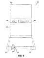
図2は、本発明のSRAMトランジスタおよび回路トポロジーが採用されえる高レベルブロック図である。SRAM状態要素のアレイ204に関連付けられるリード/ライト回路202は、入って行くライトチャネル206および出て来るリードチャネル208を有し、複数の双方向ビットラインを介してアレイ204に結合される。具体的な実施形態によれば、リードおよびライトチャネルのそれぞれは、Nビットのデュアルレールであり、ビットラインもNビットのデュアルレール(すなわちb.0およびb.1)である。しかし、これらは例示に過ぎないことが理解されよう。デマルチプレクサ210は、ライトおよびリード信号「iw」および「ir」を含む命令Iを受け取り、SRAMアレイ204と関連付けられる適切なアドレスライン(群)を選択する。リード/ライト回路202の性質は、図3〜5を参照してこれから説明される。
FIG. 2 is a high level block diagram in which the SRAM transistor and circuit topology of the present invention may be employed. A read /
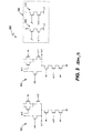
具体的な実施形態によれば、回路202は、3つのレベルの階層に構成される。以下の説明は、ライト操作中にビットライン(b.0およびb.1)のペアのうちの一つをロウに駆動するよう構成されるライト回路302および304を備えるリードおよびライト回路300(図3)によって表される第1の、最も低いレベルから始まる。イネーブル信号「en」は、ビットラインb.0およびb.1をプリチャージし(pre-charges)、システムがライトできる状態にあるときを知らせ、サイクルごとにリセットされる。信号w.0は、選択されたSRAMセル(群)に論理「0」が書き込まれるときにハイになり、信号w.1は、選択されたSRAMセル(群)に論理「1」が書き込まれるときにハイになる。回路302を参照し、例えば、en、iw、およびw.0のハイが一致すると、プリチャージされたビットラインb.1がプルダウンされ、ビットラインb.0がハイのまま維持される。この結果、アドレスラインが選択されたバス上のセルに、論理「0」が書き込まれることになる。書き込み完了は、信号w.0およびw.1を併せてNORをとることによって示され、これはライト完了信号_W.v.になる。そのビットラインがライト回路によって駆動されていることをチェックすることによって、さらなるトランジスタを使うことにはなるが、1つのタイミング仮定をなくすことも可能である。
According to a specific embodiment, the
リード回路306は、リード回路308および310を備える。リード制御信号「ir」がハイになる(したがって_irがロウになる)とき、回路308および310中の対応するトランジスタは、ターンオンされる。同時に、ビットラインb.0およびb.1を、対応する状態要素の内部状態x.0およびx.1に曝すアドレスラインが選択されている。この結果、b.0およびb.1のうちの1つがロウになり(状態要素の状態に依存して)、それにより信号ラインr.1およびr.0のうちの対応する1つにおいてセンスされ、例えばもしb.0がロウになるなら、r.1はハイになる。イネーブル信号「en」およびリード制御信号「ir」は、互いに排他的であり、それによってビットラインがプリチャージしているときには、リード動作がイネーブルされることを防止することに注意されたい。代替の実施形態によっては、回路308および310は、センスアンプと置換されえることに注意されたい。
The
図4は、図3のリードおよびライト回路300が4回繰り返され、この1回は、4つのSRAM状態要素のうちのそれぞれについてであり、4つのSRAM状態要素のそれぞれは、SRAMアレイ中の状態要素のセットに対応する、リード/ライト回路202の階層400の第2の、つまり次のレベルを示す。アレイ中の状態要素は、状態要素回路に対する容量性負荷を減らすように複数のセットに分割される。さまざまな実施形態によれば、SRAMアレイのサイズに依存して、セットの個数は変わりえる。示される実施形態は、回路の1ビット版が4つのセットである。
FIG. 4 illustrates the read and write
回路306の4つのインスタンスについての4つの_ir信号は、互いに排他的なロウであり、すなわち1つだけが任意の時刻においてロウであることができる。よって、回路402および404は、反転されたリードの全てがハイになるとき、リードラインr.0およびr.1をリセットする。リード信号r.0およびr.1をそれぞれリード信号R.0およびR.1にブーストするために、ハーフバッファ回路406がオプションとして採用されえ、これは、r.0およびr.1上の負荷をバッファし、リード完了回路を効率的に提供する、すなわちリード完了信号R.v.を提供する。よって、適切な回路およびフロー制御を用いて、従来のSRAM状態要素(そのビットラインのデュアルレール状の特性を持つ)に対するリード動作は、準耐遅延(quasi-delay-insensitive)非同期システムの適切なイベントドリブンデュアルレールチャネルフォーマットである出力を作ることが可能である。ライト完了信号_W.v.は、信号w.0およびw.1をNORゲート408で論理的に結合することによって発生される。示される具体的な実施形態によれば、_W.vの発生は、オプションとしてそのビットに書き込まないことを示す第3信号w.2を含みえ、特定のビットをマスクするのに用いられえる個別のビットイネーブルを実現しえる。よって、個別のビット群(またはビット群のグループ、すなわちニブル群およびバイト群)の選択的書き込みは、非常にローコストで達成されえる。
The four _ir signals for the four instances of
具体的な実施形態によれば、遅延のバラツキに遭遇したときのこれら回路のロバストさは、ビットラインの駆動に関するある簡単なタイミングの仮定に根拠が置かれている。すなわち、イネーブル信号「en」がロウに駆動されて、ビットラインがプリチャージさせられるとき、アクノリッジはなく、この仮定は、そうでなければ耐遅延動作を確かにするようビットラインが充分に短い期間でプリチャージされることにある。同様に、ビットラインがライト動作のためにロウまたはハイに駆動されるとき、アクノリッジはなく、この仮定は、ビットラインおよび状態ビットが充分に短い期間で安定化することである。これら仮定は、かなりのマージンを有し、より複雑な完了回路のための必要をなくす。例えば、これら仮定は、書き込み完了が信号w.0およびw.1の簡単な組み合わせであることを可能にする。ある実施形態によれば、アドレスチャネルのデマルチプレクシングもアクノリッジされなくてもよく、さらなるタイミングの仮定は、デマルチプレクシング動作が、そうでなければ耐遅延動作を可能にするよう充分な期間内に起こることである。 According to a specific embodiment, the robustness of these circuits when encountering delay variations is based on some simple timing assumptions regarding the driving of the bit lines. That is, when the enable signal “en” is driven low and the bit line is precharged, there is no acknowledge, and this assumption is that the bit line is short enough to ensure otherwise delay-tolerant operation. It is to be precharged with. Similarly, when the bit line is driven low or high for a write operation, there is no acknowledge and the assumption is that the bit line and the status bit stabilize in a sufficiently short period. These assumptions have significant margins and eliminate the need for more complex completion circuits. For example, these assumptions allow write completion to be a simple combination of signals w.0 and w.1. According to certain embodiments, address channel demultiplexing may also not be acknowledged, and additional timing assumptions may be made within a time period sufficient to allow the demultiplexing operation to otherwise allow delay tolerant operation. Is what happens.
図5は、4ビットブロックを4セット作るために図4の回路が4回複製される(ブロック400によって表される)リード/ライト回路202の階層の第3の、つまり次に高いレベルを示す。上述のように、ブロック400のそれぞれは、4つのブロック300を含み、これらはそれぞれ、ロウの中のNビット(例えば32または64ビット)のそれぞれについて複製される。
FIG. 5 shows a third or next higher level of the read /
デマルチプレクサ(例えば図2のデマルチプレクサ210)によって受け取られる命令「I」は、どのセットが選択されるべきかを特定する。具体的な実施形態によれば、動作のタイプ、および4つのセットのうちのどれが選択されるかを特定するために1of8コード(I.0からI.7)が用いられる。図5を再び参照して、リードセレクト(I.0からI.3)は、反転され(ブロック504)、上述のような信号_ir.0から_ir.3の互いに排他的ロウであるセットを得る。ライトセレクト(I.4からI.7)は、バッファされ(ブロック506)、信号iw.0からiw.3を得る。このバッファリングのアプローチは、これを行うのに充分な時間がある場合に適する。代替として、時間を節約することが望まれる場合には、ブロック504および506は、簡単なバッファリングアプローチよりも速くそれらのそれぞれの値をラッチおよびアクノリッジすることができるパイプラインされた回路を備えうる。
The instruction “I” received by the demultiplexer (eg,
バッファされたライトセレクト、ライト完了信号_W.v[0]から_W.v[3]、およびリード完了信号_R.v[0]から_R.v[3]が完了され(ブロック512)、w.vおよびr.vを発生する。イネーブル信号は、信号ENを発生するために、偶数個のインバータ(例えばブロック514)を有するインバータチェーンを用いて「ランプアップ」されえる。それから信号ENは、C要素を用いてw.vおよびr.vのそれぞれと結合され、それらの出力は、NANDがとられて、命令チャネルに動作が完了され、他の命令が発行されえることをアクノリッジする命令アクノリッジI.eを発生する(ブロック516)。加えて、それぞれのライト動作について、ライトアクノリッジ信号W.eが発生され、ライトチャネル(例えば図2の回路202)にアクノリッジし、ライトチャネルが次のトークンについて準備ができていることを示す。
Buffered write select, write completion signals _Wv [0] to _Wv [3], and read completion signals _Rv [0] to _Rv [3] are completed (block 512), generating wv and rv . The enable signal may be “ramped up” using an inverter chain having an even number of inverters (eg, block 514) to generate the signal EN. The signal EN is then combined with each of wv and rv using a C element and their outputs are NANDed to complete the operation on the instruction channel and acknowledge that other instructions can be issued. An acknowledge Ie is generated (block 516). In addition, for each write operation, a write acknowledge signal W.e is generated, acknowledging the write channel (eg,
例示的物理トポロジーを有し、図3〜5の回路を用いて実現される単一のポートのSRAMのより詳細な説明が図6を参照してこれから記載される。示されるトポロジーは例示に過ぎず、本発明の範囲から逸脱することなく幅広いトポロジーが採用されえることが理解されよう。 A more detailed description of a single port SRAM having an exemplary physical topology and implemented using the circuits of FIGS. 3-5 will now be described with reference to FIG. It will be appreciated that the topology shown is exemplary only and that a wide variety of topologies can be employed without departing from the scope of the present invention.
SRAM600は、デマルチプレクサ606および制御回路608のそれぞれの側に2つの実質的に同一のブロック602および604を備える。48ビット幅のメモリシステムについては、ブロック602および604のそれぞれは、図1〜5に示されるSRAM状態要素およびリード/ライト回路の6つの実質的に同一のロウを含む。ロウの異なる個数は、異なる幅に対応し、例えば32ビット幅メモリシステムについては、ブロック602および604のそれぞれは4つのロウを有する。それぞれのそのようなロウ(その例はブロック604の下に示される)は、図5の回路の1つのインスタンス(4×4のブロック610)、およびそれに続いてSRAM状態要素の64個のカラム614を含み、それぞれのカラムは、16のそのような状態要素を備え、すなわち、4情報ビットおよび4セットである。状態要素の64×16のアレイに関連付けられるビットライン(不図示)は、ビットラインの値をホールドするスタティサイザを有する。よって、SRAMブロック600は、より大きいSRAMメモリシステムを作るために反復できる1.5kBのブロックである。
本発明の具体的な実施形態によってアドレス情報を発生するためにどのようにデマルチプレクサ606が実現されえるかの詳細が図7を参照してこれから説明される。この実施形態によれば、アドレス情報は、3つの1of4コードで入って来て、このコードは、64個の3入力ANDゲート、すなわちインバータを持つNANDゲート(ブロック702)を用いてSRAMについての従来の1ofNコード(この場合、1of64)に変換される。具体的な実施形態によれば、アドレス発生回路は、1ofNコードを完了させるために完了回路(completion circuitry)を用いて耐遅延に作られえる。そのような完了回路は、例えば、アドレス完了信号a.vを発生する完了ツリー704(または任意の等価物)を備えうる。
Details of how the
リード動作については、a.vはアドレス発生の中間状態(neutrality)の完了を表すが、それは、リードラインそれら自身がアドレスの有効性を完了させるからであり、すなわちリードはアドレスなしでは起こりえなかったはずだからである。ライト動作については、a.vはアドレスの有効性および中間状態を表す。上述のデマルチプレクサ実現例は単なる例示であり、本発明を限定するために用いられるべきではないことに注意されたい。 For read operations, av represents the completion of the neutrality of address generation, because the read lines themselves complete the validity of the address, i.e., the read could not have happened without the address. That's why. For a write operation, a.v represents the validity and intermediate state of the address. It should be noted that the demultiplexer implementation described above is merely exemplary and should not be used to limit the present invention.
加えて、図6の4×4のブロック610のインスタンスの全てについての命令アクノリッジ信号I.eは、例えば、8入力C要素ツリーまたは完了信号d.vを発生する等価な構造を用いて完了される。アドレス完了信号a.v、完了信号d.v、およびリセット信号(回路全体をリセットするグローバル信号)の反転されたものが、イネーブル信号enを発生する回路706への入力として用いられ、この信号はそれから、制御チャネル全体についての、かつ1of4アドレスコードの全てについてのアクノリッジを含むそのさまざまな使用のために、メモリブロック全体にわたってブロードキャストされる。
In addition, the instruction acknowledge signal I.e for all instances of the 4 × 4
本発明のさまざまな実施形態によれば、SRAMブロックにリペア機能が導入されえる。そのような実施形態によれば、65番目のアドレスラインおよび対応する状態要素が上述の設計中に含まれる。もし、製造されたチップの試験中に、最初の64アドレスのうちの1つについてビットエラーが識別されると、アドレスデコーディング回路は、アドレス翻訳を実行することによって、65番目のアドレスが検出された不良アドレスの代わりに置換されえるようイネーブルされえる。このことは、例えば、64から65アドレスに変換するデマルチプレクサの前に挿入されたステージを含みえる。理解されるように、そのような能力は、それが使用されるときにこの追加回路を実現するさまざまな完了回路への代替物を含みえる。 According to various embodiments of the present invention, a repair function may be introduced into the SRAM block. According to such an embodiment, the 65th address line and the corresponding state element are included in the above design. If, during testing of the manufactured chip, a bit error is identified for one of the first 64 addresses, the address decoding circuit will detect the 65th address by performing address translation. It can be enabled to be replaced in place of a bad address. This may include, for example, a stage inserted before the demultiplexer that translates from 64 to 65 addresses. As will be appreciated, such capabilities may include alternatives to various completion circuits that implement this additional circuit when it is used.
本発明のさまざまな他の実施形態によれば、上述のSRAM設計は、バンク非同期SRAM設計を実現するために追加の回路と共に採用されえる。図8に示される一つのそのような実施形態において、上述のように設計された複数のSRAMバンク802は、スプリット804を採用して、ライトチャネルWを介したライト動作のためのバンクを選択し、マージ806を採用して、リードチャネルRを介したリード動作のためのバンクを選択する。これらの選択は、1つのリード/ライトビットおよびnビットのアドレス情報を含む制御チャネルIAに応答して達成される。
According to various other embodiments of the present invention, the SRAM design described above can be employed with additional circuitry to implement a bank asynchronous SRAM design. In one such embodiment shown in FIG. 8, a plurality of
上述のように、スプリット804は、1からQのバス(例えばQ=4)であり、このバスは、制御チャネルSを制御回路808からリードし、入力データの1つのトークンをライトチャネルLからリードし、それからそのデータをSからリードされた値によって選択されたQ出力チャネルのうちの1つに送る。マージ806は、Pから1のバス(例えばP=4)であり、これは制御チャネルMを制御回路808からリードし、それからデータのトークンをP入力チャネルのうちの1つからMからリードされた値によって選択されるようにリードし、そのデータを単一の出力チャネルRに送る。図9は、スプリット900の基本ブロック図を示す。図10は、マージ1000の基本ブロック図を示す。上で参照によって援用されたA. Linesによる「Pipelined Asynchronous Circuits」も参照されたい。
As described above, split 804 is a 1 to Q bus (eg, Q = 4) that reads control channel S from
具体的な実現例によれば、スプリット804は、1つのsplit_env部およびQ個のsplit_cell部を含み、マージ806は、1つのmerge_env部およびP個のmerge_cell部を含む。split_cellは、それぞれの出力チャネルについて複製されたスプリット804の一部を含み、split_envは、回路の残りを含む。同様に、merge_cellは、それぞれの入力チャネルについて複製されたマージ806の一部を含む。
According to a specific implementation, the
機能的には、それぞれのsplit_cell[i]は、Sが有効になるのを待ち、Sの値がiに等しい(すなわちレールSiが真である)ことをチェックする。もしそうであるなら、それは、その出力R[i]eからのイネーブルをチェックし、それがハイなら有効なデータをLからR[i]にコピーする。いったんデータがR[i]にコピーされたら、split_cell[i]は、そのイネーブルをsplit_env, se[i]に下げる。結果として、S,L,およびR[i]eは中間に戻り、その結果、split_cell[i]は、データをリセットし、se[i]を再び上げることができる。1ビットデータおよび1ビット制御(共に1of2コードとしてエンコードされる)を持つsplit_cell1100についての概略図は、図11に示される。
Functionally, each split_cell [i] waits for S to become valid and checks that the value of S is equal to i (ie, rail S i is true). If so, it checks the enable from its output R [i] e, and if it is high, copies valid data from L to R [i]. Once the data has been copied to R [i], split_cell [i] lowers its enable to split_env, se [i]. As a result, S, L, and R [i] e return to the middle so that split_cell [i] can reset the data and raise se [i] again. A schematic diagram for
split_envは、Lチャネルの有効性(validity)および中間状態(neutrality)をテストし、split_cell からse[0..Q-1]の論理ANDを計算し、SおよびL入力チャネルについてのアクノリッジを作る。Sチャネルの有効性および中間状態は、split_cell からのアクノリッジによって黙示される。1ビットデータおよび2つのsplit_cellについてのsplit_env1200についての概略図は、図12に示される。
split_env tests the validity and neutrality of the L channel, calculates the logical AND of se [0..Q-1] from split_cell, and creates an acknowledge for the S and L input channels. The validity and intermediate state of the S channel is implied by an acknowledge from split_cell. A schematic diagram for
1ビットデータおよび1ビット制御(1of2コードとしてエンコードされる)を持つmerge_cell1300についての概略図は、図13に示される。それぞれのmerge_cell[i]は、Mが有効になるのを待ち、Mの値がiに等しい(すなわちレールMiが真である)ことをチェックする。もしそうであるなら、それはmerge_env(出力イネーブルReのレディネス(readiness)を含む)からのgo信号を待ち、入力データL[i]が有効になるのを待つ。これが起こるとき、それはL[i]の値をRにコピーする。merge_envは、Rの有効性をチェックし、rvをハイにセットすることによって、この状況を全てのmerge_cellに戻すようブロードキャストする。次に、merge_cellは、そのイネーブルme[i]およびL[i]eを下げる。いったんMおよびL[i]データが中間に戻り、goが下げられると、Rが中間に戻り、rvが下げられ、merge_cellはイネーブルme[i]およびL[i]eを上げる。
A schematic diagram for
1ビットデータおよび2つのマージセルについてのmerge_env1400についての概略図は、図14に示される。merge_envは、Rイネーブルのレディネスをチェックし、goを上げる。Mは、直接にmerge_cellに行き、それらのうちの1つがRを新しい有効な値にセットすることによって応答する。それからmerge_envは、rvを上げ、その後、merge_cellは、me[i]で応答する。merge_envは、これらアクションの完了をチェックし、それからMをアクノリッジする。いったんMが再び中間状態になり、Rがアクノリッジしたら、merge_envは、goを下げ、これはmerge_cellがme[i]をリセットするようにする。またmerge_envは、Rを中間状態の値にリセットする。いったんこれらのアクションが完了すると、merge_envは、Mのアクノリッジを下げる。
A schematic diagram for
SRAM状態要素の読み出しは比較的遅いので、リード動作は、ビットライン上の部分的な信号のスイングだけを用いて、センスアンプを用いてビットラインのスイングを検出することで実行されえる。本発明の具体的な実施形態は、そのようなアプローチを採用すると想定される。しかし、半導体プロセスの寸法が小さくなり続けるにつれ、センスアンプの一貫した信頼性高い動作を得ることはますます難しくなってきている。実際、経済的および技術的リソースの多くがこの問題のために用いられてきているが、結果はさまざまである。それぞれの新しいプロセスのためのアナログ回路の信頼性高い動作を実現するためには時間が必要とされるだけかもしれない。あるいは、実際の物理的限界が最終的にはセンスアンプが新しい世代のプロセスで成功して製造されえるかを決定するのかもしれない。 Since reading of the SRAM state element is relatively slow, a read operation can be performed by using only a partial signal swing on the bit line and detecting the bit line swing using a sense amplifier. Specific embodiments of the present invention are envisioned to employ such an approach. However, as semiconductor process dimensions continue to shrink, it becomes increasingly difficult to obtain a consistent and reliable operation of the sense amplifier. In fact, many economic and technical resources have been used for this problem, but the results vary. Only time may be required to achieve reliable operation of the analog circuitry for each new process. Alternatively, the actual physical limits may ultimately determine whether the sense amplifier can be successfully manufactured in a new generation of processes.
いずれにしても、具体的な実施形態によれば、本発明によって設計されたバンクSRAMは、センスアンプを採用せず、その代わりに、ビットラインがそのフルスイングで振れることを可能にする。これは、特定のバンクの動作を遅くするが、適切な個数のSRAMバンクおよびフロー制御によって、実効データレートは、任意の1つのバンク動作だけよりも大幅に高くなりえる。具体的な実施形態によれば、これを促進するために、マージ806は、フルバッファマージ回路として実現され、これは1つのデータトークンをその入力において、もう一つをその出力において記憶しえる。このフルバッファリングは、異なるバンクへの不連続リード動作でのフルスピードを可能にするために、非同期チャネルの高速パフォーマンスを利用する。 In any case, according to a specific embodiment, the bank SRAM designed according to the present invention does not employ a sense amplifier, but instead allows the bit line to swing at its full swing. This slows down the operation of a particular bank, but with an appropriate number of SRAM banks and flow control, the effective data rate can be significantly higher than just any one bank operation. According to a specific embodiment, to facilitate this, merge 806 is implemented as a full buffer merge circuit, which can store one data token at its input and another at its output. This full buffering takes advantage of the high speed performance of the asynchronous channel to allow full speed with discontinuous read operations to different banks.
図15に示される代替のバンク非同期SRAM設計によれば、図8のマージ806を、この場合、4つのSRAMブロック1504をリードチャネルに接続するクロスバー1502で置き換えることによって、複数のリードチャネルR1およびR2がサポートされえる。さまざまな実施形態によれば、幅広い種類のクロスバー設計のうちの任意のものが採用されえる。例えば、そのようなクロスバーを構成するためには、図9〜14を参照して上述のスプリットおよびマージ回路の組み合わせが採用されえる。加えて、2002年4月30日に出願されたASYNCHRONOUS CROSSBAR WITH DETERMINISTIC OR ARBITRATED CONTROLと題された係属中の米国特許出願第10/136,025号(その開示全体が全ての目的のためにここで参照によって援用される)に記載されたクロスバー回路のうちの任意のものがクロスバー1502を実現するために採用されえる。ある実施形態によれば、データを複数の入力チャネルのうちの任意のものから、複数の出力チャネルのうちの任意のものに、ルーティング制御情報に基づいてルーティングするよう動作可能なクロスバーが採用される。入力チャネルおよび出力チャネルのそれぞれの組み合わせは、複数のリンクのうちの一つを備える。このクロスバーは、リンクのそれぞれの上で確定的にデータをルーティングし、それによってルーティング制御情報によって表される順序付けを部分的に保存するよう動作可能である。異なるリンク上のイベントは、無相関である。
According to the alternative bank asynchronous SRAM design shown in FIG. 15, the
実際、スプリット804およびマージ806の両方は、基本SRAM状態要素に何らの変更も加えることなく、SRAMのポート能力(ported-ness)を増すために、クロスバーによって置き換えされえる。加えて、いずれかの側(すなわちリードまたはライト)のポートの個数は、2つに限定されない。しかし、現実的な個数は、SRAMバンクの個数に相関し、すなわちもし4バンクしか存在しないなら、4個より多いリードポートは決してフルには利用されないだろう。 In fact, both split 804 and merge 806 can be replaced by a crossbar to increase the ported-ness of the SRAM without making any changes to the basic SRAM state element. In addition, the number of ports on either side (ie read or write) is not limited to two. However, the realistic number correlates with the number of SRAM banks, ie, if there are only 4 banks, more than 4 read ports will never be fully utilized.
加えて、図15に示されるように、このようなSRAM設計(および実際のところ本発明の範囲内の任意の非同期SRAM設計)は、そうでなければ同期システムであるシステムにおいて、同期・非同期(S2A)変換回路1506および非同期・同期(A2S)変換回路1508をそれぞれライトおよびリードポート上で用いて採用されえる。具体的な実施形態によれば、適切な変換回路は、2002年8月1日に出願されたTECHNIQUES FOR FACILITATING CONVERSION BETWEEN ASYNCHRONOUS AND SYNCHRONOUS DOMAINSと題される係属中の米国特許出願第10/212,574号に記載され、その全体が全ての目的のためにここで参照によって援用される。
In addition, as shown in FIG. 15, such an SRAM design (and indeed any asynchronous SRAM design within the scope of the present invention) can be used in a system that is otherwise a synchronous system. S2A)
バンクスピードがポートスピードよりも遅い複数のバンクを持つSRAM設計(単一のまたは複数のポートをもつ)において、非同期SRAMは、平均のポートスピードのパフォーマンスに近づくが、全てのアクセスパターンについてではない。そしてもしより低いパフォーマンスのアクセスパターンが予め計算されないなら、これはシステムの観点からは実質的に非確定的である。もし非同期メモリが同期システムにおいて用いられるなら(図15を参照して上述のように)、そしてその同期システムが「確定的な」パフォーマンスを要求するなら、システムは、バンクスピードに等価な全体的なSRAMパフォーマンスに頼るかもしれず、または異なるありえる実施形態においては、非同期SRAMにおけるバンクコンフリクトを検出することに基づいて同期システムに「待機状態」を知らせ、それによって同期システムがそのステートマシンに、「このサイクルではSRAMアクセスなし」をエンコードする条件を構築し、よって「確定的に」振る舞い、しかしながら平均としては非同期SRAMポートのパフォーマンスを実現できるようにするための論理が加えられえる。 In SRAM designs with multiple banks (with single or multiple ports) where the bank speed is slower than the port speed, asynchronous SRAM approaches average port speed performance, but not for all access patterns. And if a lower performance access pattern is not calculated in advance, this is substantially non-deterministic from a system perspective. If asynchronous memory is used in a synchronous system (as described above with reference to FIG. 15), and if that synchronous system requires “deterministic” performance, then the system In an embodiment that may or may not rely on SRAM performance, it informs the synchronization system of a “waiting state” based on detecting a bank conflict in the asynchronous SRAM, which causes the state machine to notify the state machine “This cycle. Now build a condition that encodes "no SRAM access" and thus behave "deterministically", but on average, logic can be added to enable performance of the asynchronous SRAM port.
図8および15のバンクSRAM設計は、単一のポートの6T SRAM状態要素に基づくSRAM設計と共に、以下にその具体的な実現例が説明されるデュアルポート10T SRAM状態要素を採用するものにも適用可能であることに注意されたい。
The bank SRAM design of FIGS. 8 and 15 applies to those employing
本発明のさらなる実施形態によれば、従来の10個のトランジスタの(10T)デュアルポートSRAM状態要素を採用するSRAMブロックが提供される。そのような10T状態要素1600の例は図16に示され、ここで2つのバスが採用され、1つはライトであり、もう一つはリードである。すなわち、ライトバスライン_w.0および_w.1は、状態要素1600に書き込むためにアドレスラインiwと併せて用いられ、一方、リードバスライン_r.0および_r.1は、状態要素1600から読み出すためにアドレスラインirと併せて用いられる。図1の6T状態要素と比較して、10T状態要素は、より多くのダイ面積を要求するが、ずっと速い。加えて、分離されたリードおよびライトバスのために、SRAMバンク内の異なるアドレスに対する実質的に同時のリードおよびライト動作が10T状態要素では起こりえる。デュアルポート10T実施形態は、例えば、スピードに対する要求が面積の問題を圧倒する場合、またはメモリのサイズ(どの程度の情報が記憶されるべきであると意図されるかについて)が比較的小さい(例えばレジスタファイル)場合の応用例において有用でありえる。実施形態の後者のタイプにおいて、メモリが充分に小さい場合、SRAMをセット群に分割する必要は大きく減るか、まったくなくなりえることが理解されよう。よって、セット群を持つ実施形態もセット群を持たない実施形態も両方が想定される。
In accordance with a further embodiment of the present invention, an SRAM block employing a conventional 10 transistor (10T) dual port SRAM state element is provided. An example of such a
10T状態要素を採用する非同期SRAMの具体的な実現例(例えば図16の状態要素1600)が図17〜21を参照してこれから説明される。階層フレームワークおよび実施形態を参照して上述の実現例の詳細の多くがデュアルポート実施形態に充分に類似するので、そのような詳細は簡潔さのためにここでは再び説明されないことが当業者には理解されよう。すなわち、2つのタイプの実施形態の間の大きな差だけが説明される。また具体的な実現例によれば、10T実施形態は、そのような実施形態が単一のタイミングの仮定、すなわち10T状態要素はライト信号に応答してラッチされているということだけを用いて実現されえる点において、前述の実施形態よりも遅延バラツキに対してよりロバストでありえることが理解されよう。
A specific implementation of an asynchronous SRAM that employs 10T state elements (eg,
図17に示されるように、イネーブル信号「en」は、リードバス(すなわち_r.0および_r.1)をプリチャージするために採用される。リードポートセル1702は、1トランジション出力ハーフバッファ(one-transition output half-buffer)を備え、リード信号_r.0および_r.1をそれぞれR.0およびR.1にブーストし、同時にリード完了信号_r.vも提供する。よって、単一ポート6T実施形態(例えば図4の回路406)のように、従来の10T SRAM状態要素上でのリード動作は、非同期システムの適切なイベントドリブンデュアルレールチャネルフォーマットである出力を作ることできる。しかし、リードポートセル1702は、単一ポートの設計の対応するものより2つのより少ないトランジションを有する。
As shown in FIG. 17, the enable signal “en” is employed to precharge the read bus (ie, _r.0 and _r.1). The read
ライトポートセル1704も比較的単純であり、単に信号w.0およびw.1を反転し、ライトバスを出力で駆動し、同時にライト完了信号_w.vも発生する。情報ビットの個数に依存して、全ての対応する信号_w.v(ライト動作について)、または全ての対応する信号_r.v(リード動作について)は、Nが情報ビットの個数であるとき、log2(N)ステージを有するMuellerのC要素を用いて6T実施形態についてと同じように達成されえる。同様に、アドレス完了も同じようにして、すなわち上述のようにORツリーで達成されえる。
The
図16において示される10T SRAM状態要素に基づき、図17のリードおよびライトセルを含むデュアルポート10T実施形態は、図18に示される。アレイは、SRAM状態ビットの32×4Nアレイとして示されるが、これは例示目的だけの特定の設計に過ぎないことに注意されたい。ビットラインおよびビットの任意の個数がサポートされえることが理解されよう。
Based on the 10T SRAM state element shown in FIG. 16, a
ライト制御1802は、ライトポートセル1704からの_w.vのビット当たり4個のライト完了信号インスタンスを結合する。ライト制御1802は、信号kwを通じたアドレス制御と共にハンドシェークし、jweを作る。ライト制御1802は、ライト完了タイミングの仮定を利用して、4ビットライトデータWをより大きなSRAMにアクノリッジする。ライト制御1802の具体的な実現例は図19に示される。C要素1804は、N個のライトニブル完了信号jweを集め、ライトデマルチプレクシングプリチャージ信号jw.eを作る。
Write
リード制御1806は、リードポートセル1702からの_r.vのビット当たり4個のリード完了信号インスタンスを結合する。リード制御1806は、信号krを通じたアドレス制御と共にハンドシェークし、jreを作る。リード制御1806は、SRAMのリードラインをプリチャージするプリチャージ信号enも作る。リード制御1806の具体的な実現例は図19に示される。C要素1808は、N個のリードニブル完了信号jreを集め、ライトデマルチプレクシングプリチャージ信号jr.eを作る。
Read
デマルチプレクサ1810は、IAにエンコードされたアドレスおよびリード/ライト命令をデマルチプレクシングして32ラインについての個別のリードおよびライトセレクトラインにする。最適化として、リードデコードはjr.eでプリチャージされえ、ライトデコードはjw.eでプリチャージされえる。デマルチプレクサ1810の具体的な実施形態は、図20に示される。
ORゲート1812は1of32リードセレクトを完了し、信号krを作り、ORゲート1813は1of32ライトセレクトを完了し、信号kwを作る。制御1814はIAを完了し、IA完了をkrおよびkwと結合し、IAチャネルアクノリッジIA.eを作る。制御1814の具体的な実現例は、図21に示される。代替の実施形態によれば、アドレスのデマルチプレクシングはアクノリッジされず、そうでなければ耐遅延動作を可能にするためにこの動作は充分に速く達成されるというさらなるタイミングの仮定がなされる。
The
示されるように、SRAMブロック1800は、非同期4相チャネルと結合された10T SRAM状態要素1600のアレイを含む。ここで参照によって援用された文書においては、条件付きおよび非条件付き非同期チャネルが定義される。要約すれば、非条件付きチャネルは、サイクルごとにハンドシェークを通り、一方、条件付きチャネルはある制御環境下でのみサイクルを経る。SRAMブロックの具体的な実施形態によれば、命令チャネルは非条件付きである。それは、アドレスおよびリード/ライト(またはリードおよびライト)命令を、メモリへのそれぞれのアクセスについて含む。ライトチャネルは、ライト命令上で条件付きであり、Wチャネルからのデータをアレイ中に置く。リードチャネルは、リード命令上で条件付きであり、アレイからデータを取り出し、それをRチャネル上に置く。信号krおよびkwは、WおよびRチャネルを制御1814と同期させるために用いられるメカニズムである。
As shown, SRAM block 1800 includes an array of 10T
SRAMブロック1800の動作がさらに詳細にここで説明される。命令は、SRAMにチャネルIAを介して入り、デマルチプレクサ1810において1of32リードセレクト(ir)ラインまたは1of32ライトセレクトライン(iw)にデコードされる。具体的な実施形態によれば、効率のためにこのデコーディングはプリチャージされた計算においてなされる。デマルチプレクシング完了1812は、1of32コードを「完了させる」(リードについてはir、ライトについてはiw)。ライトについては、データは、ライトポートセル1704にバッファされ、状態ビット(_w.x)にわたってブロードキャストされる。ライト制御1802は、_w.vを完了し、完了信号をkwと結合し、その完了jweを発生する。ライト完了1804は、N個のjwe信号を完了し、jw.eを作り、これはある実施形態によれば、ライトセレクトのためのデマルチプレクサ1810のためのプリチャージである。このプリチャージングは、パフォーマンスのために含まれえるが、機能の実現のためには必要ではないことに注意されたい。
The operation of SRAM block 1800 will now be described in further detail. The instruction enters the SRAM via the channel IA and is decoded by the
同様に、リード時には、リードセレクトラインは、状態ビットがリードラインをプルダウンすることを可能にする。リードポートセル1702は、「パイプラインされた」バッファステージを含み、_rをRにバッファする。またリードポートセル1702は、リードラインプリチャージトランジスタを含む。リード制御1806は、リードラインを完了し、その完了をkrと結合し、リードラインプリチャージ信号enおよびそれ自身の完了信号jreを発生する。リード完了1808は、N個のjre信号を完了し、jr.eを作り、これはある実施形態によれば、デマルチプレクサ1810におけるリードセレクトライン(ir)のためのデコードをプリチャージするのに用いられる。再び、このプリチャージングは、パフォーマンスのために含まれえるが、機能の実現のためには必要ではないことに注意されたい。最後に制御1814はアドレスおよびkrおよびkw信号を完了し、命令についてのアクノリッジIA.eを発生する。
Similarly, when reading, the read select line allows a status bit to pull down the read line. Read
具体的な実施形態によれば、制御1814は、同時にSRAMアレイにライトおよびリードを行うことを可能にするために実現されえる。すなわち、リードおよびライト命令についてのアドレスが衝突しないことが保証される限り、同時のライトおよびリード命令が実行されえる。同じアドレスがリードおよびライトされているときを検出し、SRAMからリードする代わりに、ライトデータをリードポートに直接にバイパスするために、追加の回路がSRAMのバンクの外に加えられえる。
According to a specific embodiment,
さまざまな実施形態によれば、上述の回路の適切な部分を複製することによって、および追加のリードおよびライトバスを付加することによって、追加のリードおよびライトポートが加えられえる。 According to various embodiments, additional read and write ports can be added by duplicating appropriate portions of the circuit described above and by adding additional read and write buses.
本発明のさまざまな実施形態によれば、ビットラインのそれぞれは、使用されていないときにバスをそれらのプリチャージされたレベルに維持するための関連付けられたスタティサイザを有する。これれ実施形態のうちの具体的なものによれば、アナログ回路技術が、ビットラインがより速くプルダウンされることを可能にするこれらのスタティサイザに適用される。 According to various embodiments of the present invention, each of the bit lines has an associated staticizer for maintaining the bus at their precharged level when not in use. According to a specific one of these embodiments, analog circuit technology is applied to these staticizers that allow the bit lines to be pulled down faster.
本発明は、その具体的な実施形態を参照して特に示され説明されてきたが、この分野の当業者には、開示された実施形態の形態および詳細の変更は本発明の精神および範囲から逸脱することなくなされえることが理解されよう。例えば、ここで記載された回路およびプロセスは、コンパイルのさまざまな段階において、1つ以上のネットリストとして、シミュレーション言語において、ハードウェア記述言語において、半導体プロセスマスクのセットにおいて、および部分的にまたは完全に実現された半導体デバイスとして、ソフトウェア(オブジェクトコードまたは機械コード)において表現されえる(制限なく)。この分野における当業者によって理解される前述のそれぞれのさまざまな代替物も本発明の範囲内に入る。例えば、コンピュータで読み取り可能な媒体のさまざまなタイプ、ソフトウェア言語(例えばVerilog、VHDL)、シミュレーション可能な表現(例えばSPICEネットリスト)、半導体プロセス(例えばCMOS、GaAs、SiGe、など)、およびここで記載されたプロセスと共に用いられるのに適するデバイスタイプ(例えばFPGA)は、本発明の範囲内に入る。 While the invention has been particularly shown and described with reference to specific embodiments thereof, those skilled in the art will recognize that changes in the form and details of the disclosed embodiments can be made without departing from the spirit and scope of the invention. It will be understood that this can be done without departing. For example, the circuits and processes described herein may be used at various stages of compilation as one or more netlists, in a simulation language, in a hardware description language, in a set of semiconductor process masks, and partially or fully As a semiconductor device realized in (1), it can be expressed in software (object code or machine code) (without limitation). Each of the various alternatives described above as understood by those skilled in the art also fall within the scope of the invention. For example, various types of computer readable media, software languages (eg, Verilog, VHDL), simulatable representations (eg, SPICE netlist), semiconductor processes (eg, CMOS, GaAs, SiGe, etc.), and described herein Device types (e.g., FPGAs) that are suitable for use with the processed process are within the scope of the present invention.
最後に、さまざまな実施形態を参照してここでは本発明のさまざまな利点、局面、および目的が説明されてきたが、本発明の範囲はこれら利点、局面、および目的を参照して限定されるべきではない。むしろ、本発明の範囲は、添付の特許請求の範囲を参照して決定されるべきである。 Finally, while various advantages, aspects, and objects of the present invention have been described herein with reference to various embodiments, the scope of the present invention is limited with reference to these advantages, aspects, and objects. Should not. Rather, the scope of the invention should be determined with reference to the appended claims.
Claims (12)
前記SRAM周辺回路は、
前記イネーブル信号に応答してビットラインをプリチャージし、書き込み動作時に前記ライト信号に応じて前記ビットラインを駆動するライト回路と、
前記ラッチの仮定およびプリチャージの仮定の少なくともいずれか一方を実行するライト完了回路であって、前記ライト信号を論理的に結合し、書き込み動作の完了を示すライト完了信号を発行するライト完了回路と
を備える、SRAM。A static random access memory (SRAM) comprising a plurality of SRAM cells and an SRAM peripheral circuit, wherein the SRAM peripheral circuit interfaces with an external asynchronous circuit and responds to a write signal on a bit line included in the SRAM peripheral circuit In a delay-insensitive manner if at least one of the latch assumption of the SRAM cell and the assumption of sufficient precharge of the bit line in response to an enable signal indicating completion of a previous memory access operation is satisfied. Enables reading and writing of SRAM cells ,
The SRAM peripheral circuit is
A write circuit that precharges a bit line in response to the enable signal and drives the bit line in response to the write signal during a write operation;
A write completion circuit for executing at least one of the latch assumption and the precharge assumption, the write completion circuit logically combining the write signals and issuing a write completion signal indicating completion of a write operation;
An SRAM.
前記第1受け側からのイネーブル信号がハイになるとき、前記第1送り側が、データ信号を有効にセットし、
前記有効なデータ信号を受け取ると、前記第1受け側は、前記イネーブル信号をロウにし、
前記ロウイネーブル信号を受け取ると、前記第1送り側は、前記データ信号を中間レベルにセットし、および
前記中間レベルのデータ信号を受け取ると、前記第1受け側は、前記イネーブル信号をハイにする
SRAM。2. The SRAM of claim 1, wherein the external asynchronous circuit is characterized by an event driven protocol, and the event driven protocol between a first sending side and a first receiving side in the external asynchronous circuit is:
When the enable signal from the first receiving side goes high, the first sending side sets the data signal validly,
Upon receiving the valid data signal, the first receiver sets the enable signal low,
Upon receiving the row enable signal, the first sending side sets the data signal to an intermediate level, and upon receiving the intermediate level data signal, the first receiving side sets the enable signal to high. SRAM.
Applications Claiming Priority (3)
| Application Number | Priority Date | Filing Date | Title |
|---|---|---|---|
| US48753603P | 2003-07-14 | 2003-07-14 | |
| US60/487,536 | 2003-07-14 | ||
| PCT/US2004/022679 WO2005008672A2 (en) | 2003-07-14 | 2004-07-13 | Asynchronous static random access memory |
Publications (2)
| Publication Number | Publication Date |
|---|---|
| JP2007531957A JP2007531957A (en) | 2007-11-08 |
| JP4904154B2 true JP4904154B2 (en) | 2012-03-28 |
Family
ID=34079380
Family Applications (1)
| Application Number | Title | Priority Date | Filing Date |
|---|---|---|---|
| JP2006520315A Expired - Fee Related JP4904154B2 (en) | 2003-07-14 | 2004-07-13 | Asynchronous static random access memory |
Country Status (6)
| Country | Link |
|---|---|
| US (2) | US7050324B2 (en) |
| EP (1) | EP1647030B1 (en) |
| JP (1) | JP4904154B2 (en) |
| AT (1) | ATE452408T1 (en) |
| DE (1) | DE602004024683D1 (en) |
| WO (1) | WO2005008672A2 (en) |
Families Citing this family (43)
| Publication number | Priority date | Publication date | Assignee | Title |
|---|---|---|---|---|
| US7584449B2 (en) * | 2004-11-22 | 2009-09-01 | Fulcrum Microsystems, Inc. | Logic synthesis of multi-level domino asynchronous pipelines |
| US7814280B2 (en) * | 2005-01-12 | 2010-10-12 | Fulcrum Microsystems Inc. | Shared-memory switch fabric architecture |
| US7359281B2 (en) | 2005-02-01 | 2008-04-15 | Intelliserv, Inc. | Read and/or write detection system for an asynchronous memory array |
| US7505304B2 (en) * | 2006-04-27 | 2009-03-17 | Achronix Semiconductor Corporation | Fault tolerant asynchronous circuits |
| EP2020085B1 (en) * | 2006-04-27 | 2017-11-08 | Achronix Semiconductor Corp. | Fault tolerant asynchronous circuits |
| US7504851B2 (en) * | 2006-04-27 | 2009-03-17 | Achronix Semiconductor Corporation | Fault tolerant asynchronous circuits |
| US7913201B2 (en) * | 2006-09-08 | 2011-03-22 | International Business Machines Corporation | Structure for estimating power consumption of integrated circuitry |
| US8027825B2 (en) | 2007-01-09 | 2011-09-27 | International Business Machines Corporation | Structure for testing an operation of integrated circuitry |
| US8006155B2 (en) | 2007-01-09 | 2011-08-23 | International Business Machines Corporation | Testing an operation of integrated circuitry |
| US7707535B2 (en) * | 2007-02-23 | 2010-04-27 | International Business Machines Corporation | Stitched IC chip layout design structure |
| US7703060B2 (en) * | 2007-02-23 | 2010-04-20 | International Business Machines Corporation | Stitched IC layout methods, systems and program product |
| DE102007009526B4 (en) * | 2007-02-27 | 2017-08-24 | Infineon Technologies Ag | Device for storing a binary state |
| US7916718B2 (en) * | 2007-04-19 | 2011-03-29 | Fulcrum Microsystems, Inc. | Flow and congestion control in switch architectures for multi-hop, memory efficient fabrics |
| US20080273366A1 (en) * | 2007-05-03 | 2008-11-06 | International Business Machines Corporation | Design structure for improved sram device performance through double gate topology |
| US7768325B2 (en) * | 2008-04-23 | 2010-08-03 | International Business Machines Corporation | Circuit and design structure for synchronizing multiple digital signals |
| US7958482B2 (en) * | 2008-04-30 | 2011-06-07 | International Business Machines Corporation | Stitched circuitry region boundary identification for stitched IC chip layout |
| US8006211B2 (en) * | 2008-04-30 | 2011-08-23 | International Business Machines Corporation | IC chip and design structure including stitched circuitry region boundary identification |
| US7952912B2 (en) * | 2008-06-06 | 2011-05-31 | Purdue Research Foundation | Static random access memory cell and devices using same |
| US8397130B2 (en) * | 2008-11-26 | 2013-03-12 | Arizona Board Of Regents For And On Behalf Of Arizona State University | Circuits and methods for detection of soft errors in cache memories |
| US8370557B2 (en) * | 2008-12-19 | 2013-02-05 | Intel Corporation | Pseudo dual-port SRAM and a shared memory switch using multiple memory banks and a sideband memory |
| US8527572B1 (en) | 2009-04-02 | 2013-09-03 | Xilinx, Inc. | Multiplier architecture utilizing a uniform array of logic blocks, and methods of using the same |
| US9002915B1 (en) | 2009-04-02 | 2015-04-07 | Xilinx, Inc. | Circuits for shifting bussed data |
| US7746109B1 (en) | 2009-04-02 | 2010-06-29 | Xilinx, Inc. | Circuits for sharing self-timed logic |
| US7982496B1 (en) | 2009-04-02 | 2011-07-19 | Xilinx, Inc. | Bus-based logic blocks with optional constant input |
| US7746108B1 (en) | 2009-04-02 | 2010-06-29 | Xilinx, Inc. | Compute-centric architecture for integrated circuits |
| US9411554B1 (en) | 2009-04-02 | 2016-08-09 | Xilinx, Inc. | Signed multiplier circuit utilizing a uniform array of logic blocks |
| US7746101B1 (en) | 2009-04-02 | 2010-06-29 | Xilinx, Inc. | Cascading input structure for logic blocks in integrated circuits |
| US7948265B1 (en) * | 2009-04-02 | 2011-05-24 | Xilinx, Inc. | Circuits for replicating self-timed logic |
| US8706793B1 (en) | 2009-04-02 | 2014-04-22 | Xilinx, Inc. | Multiplier circuits with optional shift function |
| US7733123B1 (en) * | 2009-04-02 | 2010-06-08 | Xilinx, Inc. | Implementing conditional statements in self-timed logic circuits |
| KR101646705B1 (en) * | 2009-12-01 | 2016-08-09 | 삼성전자주식회사 | Cryptographic device for implementing s-box |
| US8402164B1 (en) | 2010-10-27 | 2013-03-19 | Xilinx, Inc. | Asynchronous communication network and methods of enabling the asynchronous communication of data in an integrated circuit |
| US8644088B2 (en) | 2010-10-28 | 2014-02-04 | Hynix Semiconductor Inc. | Semiconductor memory device and semiconductor system including the same |
| US9058860B2 (en) * | 2012-03-29 | 2015-06-16 | Memoir Systems, Inc. | Methods and apparatus for synthesizing multi-port memory circuits |
| US9508405B2 (en) | 2013-10-03 | 2016-11-29 | Stmicroelectronics International N.V. | Method and circuit to enable wide supply voltage difference in multi-supply memory |
| US9361973B2 (en) * | 2013-10-28 | 2016-06-07 | Cypress Semiconductor Corporation | Multi-channel, multi-bank memory with wide data input/output |
| US10361924B2 (en) | 2014-04-04 | 2019-07-23 | International Business Machines Corporation | Forecasting computer resources demand |
| US10043194B2 (en) | 2014-04-04 | 2018-08-07 | International Business Machines Corporation | Network demand forecasting |
| US9385934B2 (en) | 2014-04-08 | 2016-07-05 | International Business Machines Corporation | Dynamic network monitoring |
| US10439891B2 (en) | 2014-04-08 | 2019-10-08 | International Business Machines Corporation | Hyperparameter and network topology selection in network demand forecasting |
| US10713574B2 (en) | 2014-04-10 | 2020-07-14 | International Business Machines Corporation | Cognitive distributed network |
| DE102014106909B4 (en) * | 2014-05-16 | 2019-08-14 | Infineon Technologies Ag | Method for accessing a memory and memory access circuit |
| TWI609375B (en) | 2016-01-21 | 2017-12-21 | 國立成功大學 | Asynchronous two word line driving memory cell and memory with the memory cell |
Family Cites Families (46)
| Publication number | Priority date | Publication date | Assignee | Title |
|---|---|---|---|---|
| JPS6395540A (en) * | 1986-10-09 | 1988-04-26 | Nec Corp | Memory interface circuit |
| JPS63173143A (en) * | 1987-01-13 | 1988-07-16 | Nec Corp | Memory interface circuit |
| JPH0322289A (en) * | 1989-06-19 | 1991-01-30 | Hitachi Ltd | Dynamic ram |
| JPH0359884A (en) * | 1989-07-27 | 1991-03-14 | Nec Corp | Semiconductor storage device |
| US5752070A (en) * | 1990-03-19 | 1998-05-12 | California Institute Of Technology | Asynchronous processors |
| JPH04328663A (en) * | 1991-04-26 | 1992-11-17 | Fuji Xerox Co Ltd | Method and device for dram access arbitration |
| JP3153568B2 (en) * | 1991-07-03 | 2001-04-09 | 株式会社東芝 | Multiport RAM memory cell and multiport RAM |
| JPH05233320A (en) * | 1992-02-19 | 1993-09-10 | Mitsubishi Electric Corp | Microcomputer |
| JPH05289989A (en) * | 1992-04-15 | 1993-11-05 | Sony Corp | Multi-output delay circuit |
| JPH05334261A (en) * | 1992-06-04 | 1993-12-17 | Japan Radio Co Ltd | High speed asynchronizing communication system at the time of write access |
| US5268863A (en) * | 1992-07-06 | 1993-12-07 | Motorola, Inc. | Memory having a write enable controlled word line |
| JPH0628865A (en) * | 1992-07-10 | 1994-02-04 | Fujitsu Ltd | Semiconductor memory device |
| JP2869336B2 (en) * | 1993-06-01 | 1999-03-10 | 松下電器産業株式会社 | Semiconductor storage device |
| JPH06342414A (en) * | 1993-06-01 | 1994-12-13 | Fujitsu Ltd | Data transfer device |
| JP2663838B2 (en) * | 1993-07-27 | 1997-10-15 | 日本電気株式会社 | Semiconductor integrated circuit device |
| JPH07240095A (en) * | 1994-02-28 | 1995-09-12 | Toshiba Corp | Multi-port memory |
| JPH0869434A (en) * | 1994-08-30 | 1996-03-12 | Oki Electric Ind Co Ltd | Transfer control circuit |
| DE69615421T2 (en) * | 1995-01-12 | 2002-06-06 | Intergraph Corp., Huntsville | Register memory with redirection option |
| JPH09128958A (en) * | 1995-11-01 | 1997-05-16 | Sony Corp | Semiconductor memory device |
| JPH09180433A (en) * | 1995-12-21 | 1997-07-11 | Kawasaki Steel Corp | First-in/first-out memory device |
| JPH09282886A (en) * | 1996-01-19 | 1997-10-31 | Sgs Thomson Microelectron Inc | Circuit and method for tracking of start of writing operation to memory cell |
| JPH09231770A (en) * | 1996-01-19 | 1997-09-05 | Sgs Thomson Microelectron Inc | Circuit and method for completing write to memory cell |
| JP3178383B2 (en) * | 1996-09-20 | 2001-06-18 | 株式会社日立製作所 | Synchronous semiconductor logic circuit |
| JPH10112646A (en) * | 1996-10-04 | 1998-04-28 | Hitachi Ltd | Semiconductor logic circuit |
| JPH10283781A (en) * | 1997-04-03 | 1998-10-23 | Matsushita Electric Ind Co Ltd | Multiport memory |
| EP0884876B1 (en) * | 1997-05-31 | 2010-02-03 | Texas Instruments Incorporated | Improved packet switching |
| US6502180B1 (en) * | 1997-09-12 | 2002-12-31 | California Institute Of Technology | Asynchronous circuits with pipelined completion process |
| US6038656A (en) * | 1997-09-12 | 2000-03-14 | California Institute Of Technology | Pipelined completion for asynchronous communication |
| US6046606A (en) * | 1998-01-21 | 2000-04-04 | International Business Machines Corporation | Soft error protected dynamic circuit |
| JP3183245B2 (en) * | 1998-03-06 | 2001-07-09 | 日本電気株式会社 | Semiconductor storage device |
| US6052772A (en) * | 1998-04-13 | 2000-04-18 | International Business Machines Corporation | Memory request protocol method |
| US6169422B1 (en) * | 1998-07-20 | 2001-01-02 | Sun Microsystems, Inc. | Apparatus and methods for high throughput self-timed domino circuits |
| US6349378B1 (en) * | 1999-03-31 | 2002-02-19 | U.S. Philips Corporation | Data processing using various data processors |
| JP4308972B2 (en) * | 1999-05-20 | 2009-08-05 | エルピーダメモリ株式会社 | Semiconductor memory device |
| JP3386117B2 (en) * | 2000-01-11 | 2003-03-17 | 日本電気株式会社 | Multilayer class identification communication device and communication device |
| US6505323B1 (en) * | 2000-02-17 | 2003-01-07 | Avant! Corporation | Methods, apparatus and computer program products that perform layout versus schematic comparison of integrated circuit memory devices using bit cell detection and depth first searching techniques |
| US6697957B1 (en) * | 2000-05-11 | 2004-02-24 | Quickturn Design Systems, Inc. | Emulation circuit with a hold time algorithm, logic analyzer and shadow memory |
| US6614438B1 (en) * | 2000-05-30 | 2003-09-02 | Koninlijke Philips Electronics N.V. | Data-processing arrangement for processing different types of data |
| US6519204B2 (en) * | 2000-11-03 | 2003-02-11 | Broadcom Corporation | Very small swing high performance CMOS static memory (multi-port register file) with power reducing column multiplexing scheme |
| JP3613726B2 (en) * | 2000-12-06 | 2005-01-26 | 日本電信電話株式会社 | Asynchronous circuit |
| JP2003004599A (en) * | 2001-06-26 | 2003-01-08 | Nkk Corp | Method for evaluating fatigue damage to structure and for display method of the same |
| US6732336B2 (en) * | 2001-10-11 | 2004-05-04 | California Institute Of Technology | Method and apparatus for an asynchronous pulse logic circuit |
| JP3811392B2 (en) * | 2001-11-27 | 2006-08-16 | 鹿島建設株式会社 | Deterioration evaluation system and life cycle cost evaluation system for concrete structures considering weather environment, deterioration evaluation method and life cycle cost evaluation method, program, recording medium |
| US7283557B2 (en) * | 2002-01-25 | 2007-10-16 | Fulcrum Microsystems, Inc. | Asynchronous crossbar with deterministic or arbitrated control |
| US6954084B2 (en) * | 2002-02-11 | 2005-10-11 | Seiko Epson Corporation | Logic circuits using polycrystalline semiconductor thin film transistors |
| US6950959B2 (en) * | 2002-02-12 | 2005-09-27 | Fulcrum Microystems Inc. | Techniques for facilitating conversion between asynchronous and synchronous domains |
-
2004
- 2004-07-13 EP EP04778275A patent/EP1647030B1/en not_active Expired - Lifetime
- 2004-07-13 AT AT04778275T patent/ATE452408T1/en not_active IP Right Cessation
- 2004-07-13 JP JP2006520315A patent/JP4904154B2/en not_active Expired - Fee Related
- 2004-07-13 DE DE602004024683T patent/DE602004024683D1/de not_active Expired - Lifetime
- 2004-07-13 WO PCT/US2004/022679 patent/WO2005008672A2/en active Application Filing
- 2004-07-13 US US10/890,816 patent/US7050324B2/en not_active Expired - Fee Related
-
2005
- 2005-08-09 US US11/200,722 patent/US7161828B2/en not_active Expired - Fee Related
Also Published As
| Publication number | Publication date |
|---|---|
| EP1647030A2 (en) | 2006-04-19 |
| US7161828B2 (en) | 2007-01-09 |
| US20050024928A1 (en) | 2005-02-03 |
| WO2005008672B1 (en) | 2005-08-18 |
| JP2007531957A (en) | 2007-11-08 |
| WO2005008672A2 (en) | 2005-01-27 |
| DE602004024683D1 (en) | 2010-01-28 |
| US7050324B2 (en) | 2006-05-23 |
| EP1647030A4 (en) | 2007-03-07 |
| ATE452408T1 (en) | 2010-01-15 |
| WO2005008672A3 (en) | 2005-07-14 |
| EP1647030B1 (en) | 2009-12-16 |
| US20050276095A1 (en) | 2005-12-15 |
Similar Documents
| Publication | Publication Date | Title |
|---|---|---|
| JP4904154B2 (en) | Asynchronous static random access memory | |
| JP4493116B2 (en) | Random access memory having read / write address bus and method for writing to and reading from the memory | |
| US6078546A (en) | Synchronous semiconductor memory device with double data rate scheme | |
| JP4951041B2 (en) | Semiconductor memory device | |
| US7940598B2 (en) | Integrated circuit memory device, system and method having interleaved row and column control | |
| US6262936B1 (en) | Random access memory having independent read port and write port and process for writing to and reading from the same | |
| JP2001167575A (en) | Semiconductor integrated circuit | |
| JP2001273774A5 (en) | ||
| JPH0738170B2 (en) | Random access memory device | |
| Dama et al. | GHz asynchronous SRAM in 65nm | |
| JP2509275B2 (en) | Semiconductor memory device | |
| KR20220008901A (en) | Shiftable memory and how to operate shiftable memory | |
| JP3136904B2 (en) | Semiconductor storage device | |
| JP3092449B2 (en) | Semiconductor storage device | |
| JPH02137189A (en) | Memory circuit and digital device | |
| JP3305975B2 (en) | Address counter circuit and semiconductor memory device | |
| JP2963953B2 (en) | Semiconductor integrated circuit | |
| JP2528930B2 (en) | Semiconductor memory device | |
| JPH06267279A (en) | Semiconductor memory device | |
| CN112116933A (en) | Travelling wave pipeline comprising synchronous stages | |
| JP2002230979A (en) | Semiconductor memory, and its control circuit | |
| Fang et al. | Locally self-resetting CMOS in multi-port register file design | |
| IL148832A (en) | Random access memory having read/write address bus and process for writing to and reading from the same | |
| JP2006092634A (en) | Semiconductor memory apparatus | |
| JPH08335397A (en) | Semiconductor memory |
Legal Events
| Date | Code | Title | Description |
|---|---|---|---|
| A131 | Notification of reasons for refusal |
Free format text: JAPANESE INTERMEDIATE CODE: A131 Effective date: 20091104 |
|
| A601 | Written request for extension of time |
Free format text: JAPANESE INTERMEDIATE CODE: A601 Effective date: 20100201 |
|
| A602 | Written permission of extension of time |
Free format text: JAPANESE INTERMEDIATE CODE: A602 Effective date: 20100208 |
|
| A521 | Request for written amendment filed |
Free format text: JAPANESE INTERMEDIATE CODE: A523 Effective date: 20100427 |
|
| A131 | Notification of reasons for refusal |
Free format text: JAPANESE INTERMEDIATE CODE: A131 Effective date: 20110201 |
|
| A521 | Request for written amendment filed |
Free format text: JAPANESE INTERMEDIATE CODE: A523 Effective date: 20110427 |
|
| TRDD | Decision of grant or rejection written | ||
| A01 | Written decision to grant a patent or to grant a registration (utility model) |
Free format text: JAPANESE INTERMEDIATE CODE: A01 Effective date: 20111213 |
|
| A01 | Written decision to grant a patent or to grant a registration (utility model) |
Free format text: JAPANESE INTERMEDIATE CODE: A01 |
|
| A61 | First payment of annual fees (during grant procedure) |
Free format text: JAPANESE INTERMEDIATE CODE: A61 Effective date: 20120106 |
|
| R150 | Certificate of patent or registration of utility model |
Ref document number: 4904154 Country of ref document: JP Free format text: JAPANESE INTERMEDIATE CODE: R150 Free format text: JAPANESE INTERMEDIATE CODE: R150 |
|
| FPAY | Renewal fee payment (event date is renewal date of database) |
Free format text: PAYMENT UNTIL: 20150113 Year of fee payment: 3 |
|
| FPAY | Renewal fee payment (event date is renewal date of database) |
Free format text: PAYMENT UNTIL: 20150113 Year of fee payment: 3 |
|
| S111 | Request for change of ownership or part of ownership |
Free format text: JAPANESE INTERMEDIATE CODE: R313113 |
|
| S531 | Written request for registration of change of domicile |
Free format text: JAPANESE INTERMEDIATE CODE: R313531 |
|
| FPAY | Renewal fee payment (event date is renewal date of database) |
Free format text: PAYMENT UNTIL: 20150113 Year of fee payment: 3 |
|
| R350 | Written notification of registration of transfer |
Free format text: JAPANESE INTERMEDIATE CODE: R350 |
|
| R250 | Receipt of annual fees |
Free format text: JAPANESE INTERMEDIATE CODE: R250 |
|
| R250 | Receipt of annual fees |
Free format text: JAPANESE INTERMEDIATE CODE: R250 |
|
| R250 | Receipt of annual fees |
Free format text: JAPANESE INTERMEDIATE CODE: R250 |
|
| R250 | Receipt of annual fees |
Free format text: JAPANESE INTERMEDIATE CODE: R250 |
|
| R250 | Receipt of annual fees |
Free format text: JAPANESE INTERMEDIATE CODE: R250 |
|
| R250 | Receipt of annual fees |
Free format text: JAPANESE INTERMEDIATE CODE: R250 |
|
| R250 | Receipt of annual fees |
Free format text: JAPANESE INTERMEDIATE CODE: R250 |
|
| LAPS | Cancellation because of no payment of annual fees |