電力変換器は、様々な負荷に送られる電力を制御する電子機器で使用される。電力入力は、110V,220V,440V,2.4kV,3.3kV等のような標準電圧において典型的には50または60Hzである。電力変換器は、入力電圧をDCレベルに整流するべく使用され、次にインバータがDC電圧をAC電圧に反転させるべく使用される。工業的な使用には、周波数および電圧の振幅を変化させることが含まれる。
DC電圧を反転させるべく使用される回路には、所定の変調パターンでターンオンおよびオフされるスイッチングデバイスが使用される。これにより、望みの周波数および振幅を有する出力信号が得られる。例えば、使用される典型的な変調パターンはパルス幅変調(PWM)である。PWMは、スイッチングデバイスの導通波形の幅を変化させる。その結果、フィルタリング後、出力電圧は正のピーク電圧から0ボルトを経由して負のピーク電圧に変化し、それによって交流電圧出力が発生する。
インバータ回路に使用される典型的なスイッチング回路には、とりわけ、バイポーラトランジスタ、絶縁ゲートバイポーラトランジスタ(IGBT)、ゲートターンオフサイリスタ(GTO)、シリコン制御整流デバイス(SCR)および集積ゲート転流サイリスタ(IGCT)が含まれる。かかるスイッチング回路には、スイッチングデバイス損失および(誘導性インバータ回路のための)還流ダイオード損失を含むいくつかのタイプの損失が生じる。
スイッチングデバイス損失
スイッチングデバイス損失には、2つの主要源がある。スイッチング損失および導電損失である。導電損失は、飽和状態での動作時に電流が導通している間のスイッチングデバイスの通常の損失である。スイッチング損失は、能動スイッチングデバイスをターンオンおよびオフにする動作に関する損失である。スイッチング損失は、デバイスにかかる高電圧とそれを流れる電流とが、オンオフ間の遷移中に同時に存在する場合に生じる。典型的には、電力変換器はいわゆる「ハードスイッチング」モード(HSM)で使用されるスイッチングデバイスとともにPWMを使用する。HSMとは、オンオフ間の遷移中にインバータスイッチングデバイスが電圧をブロックするのと同時に電流を流すスイッチングのことである。電力損失は、デバイスにかかる電圧とデバイスを流れる電流とが同時にあるこの期間中に生じる。この電力損失は、VIターンオン損失およびVIターンオフ損失と呼ばれ、HSMに対しては、スイッチングデバイスのオンおよびオフの間の各スイッチングサイクルに電力損失が生じることを示す。スイッチング損失は、デバイスのターンオンおよびオフのたびに生じるので、デバイス周波数が高いほどスイッチング損失は大きくなる。
スイッチングデバイスをターンオンにすることに関連する損失には、VIターンオン損失、(バイポーラデバイスのための)導電率変調損失およびキャパシタンス放電損失が含まれる一方で、スイッチングデバイスをターンオフにすることに関連する損失には、VIターンオフ損失および(所定条件下のいくつかのデバイスにおける)テール電流損失が含まれる。
ダイオード損失
誘導性インバータ回路のダイオードに生じるのは、導電損失(典型的にはデバイス設計と電流との関数)、導電変調損失(スイッチングデバイスがターンオンのときに生じる)、および逆回復損失(スイッチングデバイスがターンオフのときに生じる)である。
典型的な損失は、従来技術に関連するハードスイッチング回路を示す図1を参照して以下にさらに詳しく説明する。図1に示すスイッチング回路100は、スイッチング損失の著名な源を説明するために使用されるHSM回路である。スイッチング回路100はIGBTスイッチングデバイス105を含み、そのコレクタ106は、Eボルトの電圧値を有するDC電源電圧110の正端部111に接続される。IGBTスイッチングデバイス105のエミッタ107は、IGBTスイッチングデバイス105に直列のリードインダクタンスを表すインダクタ115に接続される。そして、インダクタ115は、インダクタ120およびインダクタ130に接続される。
インダクタ120は、ダイオード125のリードインダクタンスを表し、ダイオード120のカソード126に引き続き接続される。インダクタ130は、大きなフィルタインダクタであり、フィルタキャパシタ135の正端部136および負荷140の正側141に引き続き接続される。
IGBTスイッチングデバイス105のベース108にはトランジスタ駆動回路145が接続される。DC電源電圧110の負端部112、ダイオード125のアノード127、キャパシタ135の負端部137、および負荷140の負側142はアース150に接続される。
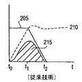
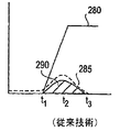
図2A−2Fは、従来技術に係る図1のスイッチング回路100に関連する、様々な電力損失が生じる時間、および損失の振幅を示す。
VIターンオフ損失
図2AはVIターンオフ損失を示す。IGBTスイッチングデバイス100(スイッチ)をスイッチオフすると、電流および電流経路(大きなフィルタインダクタが存在すると仮定)は、スイッチにかかる電圧がDC電源電圧110よりも高くなって初めて変化し、その時点で電流が降下し始める。図2Aに示すように、実線205で表されるスイッチを流れる電流は、時刻t0からt1までは一定であり、その間、破線210で表されるスイッチにかかる電圧がDC電源電圧110のレベルまで上昇する。スイッチにかかる電圧がDC電源電圧110のレベル(例えば時刻t1)に到達すると、電流はゼロに達する(時刻t2)まで降下する。なお、図2Aは、スイッチ内にテール電流(以下に説明する)がないものと仮定する。
スイッチがターンオフされると、電流は以下のようにしてダイオード125に向かって転流する。電流は、インダクタ115および120のサイズならびにDC電源電圧110よりも上の電圧レベルによって決まる速度で減衰する。すなわち、スイッチにかかる電圧がDC電源電圧110よりも高いと、DC電源電圧110を超えて上にある電圧量がインダクタ115と120との間で分割される。このとき、インダクタ115の端部117とインダクタ120の端部121とは正である。電圧はインダクタ115および120のサイズの割合で、インダクタ115の−di/dtがインダクタ120の+di/dtに等しくなるように分割される。このプロセスは、電流がスイッチにおいてゼロとなるまで続く。電流がゼロに達すると、スイッチにかかる電圧は、ほぼDC電源電圧110の電圧レベルまで降下する。
図2Aに示すように、VIターンオフ電力損失は、斜線領域215によって表され、スイッチにかかる電圧が上昇し始めて電流がゼロまで降下する前の期間中(例えば時刻t0から時刻t2まで)に生じる。VIターンオフ損失は典型的には、スイッチング損失のうち最も高いものであり、特にHSMを使用する回路において重要となり得る。例えば、電流が1,000アンペア(A)および電圧が600ボルト(V)である典型的なシステムにおいて、ピーク電力点(例えば時刻t1)における電力損失は600キロワット(kW)であり、平均電力損失は時刻t0からt2までの間でほぼ300kWになる。この時間は典型的にはスイッチング周期の10%に近づき、30kWのVIターンオフ損失になる。
テール電流損失
VIターンオフ損失がバイポーラデバイスを実装する回路および電界効果トランジスタ(FET)を実装する回路に当てはまる一方で、バイポーラスイッチングデバイスを実装するほとんどの回路に特有の付加的なターンオフ損失は、テール電流ターンオフ損失(テール電流損失)である。
図2Bはテール電流損失を示す。図2Bに示すように、破線225で表される電圧は図2Aに示すものと同じであり、実線220で表される電流は図2Aに示すものと同様に時刻t1から時刻t2までの期間中に降下する。インダクタ115および120のサイズならびにDC電源電圧110より上のスイッチにわたる電圧レベルが、時刻t2まで電流が減衰する速度を決定する。ほとんどのバイポーラデバイスにとって、スイッチングデバイス自体が電流減衰速度を決定する点(例えば時刻t2)に達すると、電流は遅い速度で減衰するため電力損失が増加する。時刻t2と時刻t3との間の電力損失がテール電流損失である。テール電流損失の原因および程度は複雑であるが、一般には、ほとんどのバイポーラデバイスを流れる電流導通に伴って生じる少数キャリアの注入によってデバイスに蓄えられる電荷に起因し、電圧および電流のターンオフ条件ならびにスイッチング時間によって決まる。例えば、IGBTを実装するスイッチングデバイスにおいては、ターンオフの所定電圧に対するスイッチングデバイスの定格電圧が低いほど低いテール電流となる。これは、デバイスに蓄えられる電荷がその飽和したオン状態においては少ないからである。
テール電流損失は典型的には、時刻t0から時刻t2までのVIターンオフ損失よりも著しく低い。VIターンオフ損失が低減し、かつ、回路が実質的に高い周波数でスイッチングされる場合でも、かかる高いスイッチング周波数におけるテール電流損失は、低い周波数における典型的なVIターンオフ損失よりも実質的に大きい。この理由ゆえに、テール電流損失は、典型的な従来技術スキームの著しい欠点とみなされている。
VIターンオン損失
図2CはVIターンオン損失を示す。スイッチがターンオンされて、スイッチにかかる電圧が降下し始めるとすぐに、スイッチを流れる電流は上昇し始める。図2Cに示すように、実線235で表されるスイッチを流れる電流は、破線240で表される電圧が降下し始めて(すなわち時刻t1にて)初めて上昇し始める。したがって、時刻t0から時刻t1まではVIターンオン損失は存在しない。VIターンオン電力損失は、斜線領域245によって表され、スイッチを流れる電流が上昇し始めて電圧がゼロまで降下する前の期間中(例えば時刻t1から時刻t2まで)に生じる。VIターンオン損失は、電圧が降下する速度および電流が上昇する速度に依存する。電流が上昇するのと同じ期間中に電圧が降下する場合は、VIターンオン損失は図2Aに示すものと同様になる(ただし、大きくはならない。スイッチをターンオフすると電流は電圧がDC電源電圧よりも上に上昇した後になって初めて降下し始めるからである)。電流が上昇するのに必要な時間が電圧が降下するのに必要な時間よりも大きいと、VIターンオン損失はそれに比例して減少する。
スイッチをターンオンすると、電流が上昇する前に電圧が実質的に0Vまで降下する場合は、スイッチにはVIターンオン損失が全く存在しない(または無視できる)。いくつかのソフトスイッチングトポロジ(1つ以上のスイッチング損失は存在しない)においては、この状態は、以下にさらに詳しく説明するように、回路トポロジの電圧および電流タイミング効果(例えばソフトスイッチングを達成するべく回路に追加されるインダクタおよびキャパシタ)の結果である。これは図2Eに示される。ここで、破線270で表される電圧は、実線265で表される電流が上昇し始める時刻(例えばt2)に先行する時刻(例えば時刻t1)において0ボルト近くまで降下する。
導電率変調損失
VIターンオン損失がバイポーラデバイスを実装する回路および電界効果トランジスタ(FET)を実装する回路に当てはまる一方で、バイポーラスイッチングデバイスを実装する回路に特有の付加的なターンオン損失は、導電率変調損失(CM損失)である。これはまた、導電変調損失とも呼ばれる。
図2Dは、バイポーラデバイスを実装するスイッチに対するCM損失を示す。図2Dに示すように、実線250で表されるスイッチを流れる電流は、図2Cに示すものと同じである。破線255で表されるスイッチにかかる電圧は、図2Cに示すものと同様に時刻t1から時刻t2までの期間中に降下する。時刻t2から時刻t3までは、導電率変調はターンオン損失の増加をもたらす。この期間は、導電率変調時間と呼ばれる。
バイポーラデバイスでは、電流が導通し始めた直後のデバイスのn領域(これはオフ状態でのブロック電圧を主に担う)は、電流が所定時間流れた後と比べて高い実効抵抗値を有する。電流が流れるとn領域の実効抵抗値は下がる。これは、(初期の電流の流れによって)n領域に注入された少数キャリアがn領域の抵抗率を低減させることにより伝導度を変調するからである。数マイクロ秒後(図2Dの時刻t2に開始)、バイポーラデバイスの順方向電圧降下は、その電流の流れに対するDC順方向降下電圧に(図2Dの時刻t3において)達する。例えば、全負荷(例えば100A)におけるバイポーラトランジスタデバイスの順方向降下は40Vである。電流が所定時間(例えば10マイクロ秒)流れた後、順方向負荷は2Vまで降下する。抵抗値は、0.4オームから0.02オームまで変化する(例えば、デバイスの抵抗値はデバイスに電流が導通するときに変調されている)。
バイポーラデバイスを実装するスイッチのターンオン損失は、斜線領域260で表され、スイッチを流れる電流が上昇し始めて電圧がゼロまで降下する前の期間中(例えば時刻t1から時刻t3まで)に生じる。CM損失は、時刻t2と時刻t3との間の損失である。
CM損失は、典型的にはVIターンオン損失よりも著しく低い。例えば、CM損失は、典型的にはVIターンオン損失の約20%である。VIターンオン損失が低減し、かつ、回路が実質的に高い周波数でスイッチングされる場合でも、かかる高いスイッチング周波数におけるCM損失は、低い周波数における典型的なVIターンオン損失よりも実質的に大きい。この理由ゆえに、CM損失は、上述のテール電流損失と同様に、典型的な従来技術スキームの著しい欠点とみなされている。
バイポーラデバイスを実装し、かつ、電流が上昇し始める前に0ボルト近くまで電圧が降下する結果となるトポロジを有する回路は、依然としてCM損失を有する。かかるCM損失は図2Fに示される。ここで、破線285で表される電圧は、実線280で表される電流が時刻t1において上昇し始めるまでに0ボルトまたはその近くになる。導電変調ゆえに、電流が時刻t1から時刻t2まで上昇すると電圧は上昇する。そして、電圧は時刻t3において低電圧まで降下する。斜線領域290で表される導電率変調損失は、時刻t1から時刻t3までで生じる。
容量性損失
すべてのスイッチングデバイスは、その電力端子にわたるキャパシタンスを有する。キャパシタンスは、IGBTおよびバイポーラトランジスタにおいては、コレクタからエミッタまでに存在する。スイッチングデバイスがターンオンされると、キャパシタンスはスイッチングデバイス内へ放電される。キャパシタに蓄えられたエネルギーはスイッチングデバイス自体に吸収されて、ターンオンスイッチング損失の一部となる。典型的には、高い周波数においてでさえも、吸収されるエネルギーは小さい。スイッチングデバイスが付加的回路なしでターンオンされる前にキャパシタンスを自然に放電するソフトスイッチングトポロジが存在する。
還流ダイオードスイッチング損失
上述のスイッチング損失は、ターンオン時の図1の還流ダイオード125のスイープアウト電流を考慮していなかった。すなわち、スイッチがオフの場合、電流はフィルタインダクタを通って還流する。スイッチがターンオンされると、ダイオードの電流はダイオードがブロックし始めるまで逆流する。この時点で、ダイオードにかかる電圧は劇的に増加し、スイッチングデバイス105内の電流における対応する電流オーバーシュートに伴う実質的な損失がダイオード内に生じる。これは、スイッチングデバイス105内の著しく大きなスイッチング損失であるが、図2Cには示されていない。
ソフトスイッチングトポロジ
ダイオードターンオンスイッチング損失を持たない(例えば、ダイオードがターンオンに先立って電圧をブロックしている)ソフトスイッチングトポロジが存在する。HSMに対しては、特に高電圧条件下でスイープアウト電流は非常に高く、ターンオン時において図2Aおよび図2Bに示すよりも損失を数倍増加させる。
いわゆる「ソフトスイッチング」モード(SSM)を使用するインバータ回路を作る試みがいくつかなされている。ここで、デバイスを流れる電流がゼロの場合に電圧がスイッチングされるか、または、デバイスにかかる電圧がゼロの場合に電流がスイッチングされる。SSMで動作する回路に対しては、1つ以上の主要なスイッチング損失は存在しない。ソフトスイッチングは、電流および/または電圧の変化を遅延させるべくインダクタおよびキャパシタを使用することによって達成される。これは、コストの増大を招く可能性があり、望ましくない回路条件および故障要求を生じさせる。さらに、SSMアプリケーションは、VIターンオンスイッチング損失またはVIターンオフスイッチング損失のどちらかを低減するが、通常は両方の損失への対処とはならない。
様々な回路トポロジまたは変調スキームを通じてのスイッチング損失に対する他の試みが行われているが、これらは1つの回路のすべてのスイッチング損失への対処となっていない。例えば、いくつかのスキームは、主要な導電デバイスにおけるVIターンオフ損失を低減すべくスイッチング中に電流または電圧を補助および/または共有する損失低減スナバ、フィルタ、または付加的な電力デバイスを含んできたが、還流ダイオードに起因するVIターンオン損失に対処していない。例えば、金属酸化膜半導体(MOS)デバイスを使用する低電力アプリケーションが電圧源インバータのスイッチングを制御することは、高速なスイッチングおよびスナバリングを使用してVIターンオフ損失を低減するが、VIターンオン損失および還流ダイオード損失が残る。CM損失は、デバイス設計の関数であり、典型的にはデバイス設計を変更することによって低減されるが、これはスイッチング損失の増加につながる。
VIターンオン損失に対処するべく他の努力がなされているが、高電力アプリケーションにおいて典型的に使用されるバイポーラデバイスに関して生じるVIターンオフ損失、ダイオード損失、または、CM損失およびテール電流損失のようなその他の損失への対処はない。かかるデバイスに対しては、スイッチング損失は電力処理限界および周波数限界の決定的要因となるのが典型的である。
なお、本出願に対応する外国の特許出願においては下記の文献が発見または提出されている。
米国特許第5,399,908号明細書
米国特許第5,448,465号明細書
米国特許第5,570,276号明細書
米国特許第6,051,893号明細書
米国特許第6,757,184号明細書
米国特許第7,113,575号明細書
米国特許第7,148,662号明細書
発明の開示
スイッチング損失を低減するためのインバータスイッチング回路である。回路は、スイッチングデバイスと、スイッチングデバイスに電気的に接続された電圧源とを有する。電圧源は、インバータスイッチング回路に通常動作電圧を与える。スイッチングデバイスはまた、スイッチングデバイスのターンオフ時間の間に、スイッチングデバイスにかかる電圧を通常動作電圧に対して実質的に低減させるためのスイッチング電圧低減機構を含む。スイッチング電圧低減機構は、スイッチングデバイスのテール電流損失時間の少なくとも一部の間はスイッチングデバイスにかかる実質的に低減された電圧を維持する。スイッチング電圧低減機構はまた、スイッチングデバイスのターンオン時にも使用されて一実施例に係るターンオンスイッチング損失を低減する。
本願は、各実施例の著しいスイッチング損失のすべてに対処する。これは付加的な回路および時にはソフトスイッチングトポロジとの併用によって行われる。これはまた、マルチスイッチPWMインバータのみにおけるロジック変更によってスイッチング損失が著しく(例えば、約50%)低減される変調技術にも対処する。これは、各PWMサイクル中に最大電流を搬送するどのスイッチをもターンオフしない変調技術を使用して行われる。
本発明の他の特徴も、以下の添付の図面および詳細な説明から明らかとなろう。
本発明は例示によって説明されるが、添付図面の図において限定されない。図面では同じ参照番号は同様の要素を示す。
詳細な説明
スイッチング電力変換器の電力損失低減がここで説明される。本発明の実施例により、インバータスイッチング回路における2つ以上のスイッチング損失を実質的に同時に除去するかまたは実質的に低減する方法および装置が与えられる。本発明の実施例により、能動スイッチングデバイスおよびダイオードのためのHSMおよびSSMのもとで複数のタイプのスイッチング損失が実質的に同時に低減される。
本発明の実施例によって、スイッチング損失が実質的に低減または除去される。これにより、効率が改善し、所定サイズの機器に対して高い定格電力が可能となり、損失を管理するために必要なヒートシンクのサイズが低減され、さらに、使用されるスイッチング周波数を著しく高くすることが可能となる。
本発明の一実施例によって、スイッチング損失源のすべてまたはほとんどは実質的に同時に低減されるので、既存のデバイスタイプを有するスイッチングが事実上無損失となる。さらに、かかる損失低減スイッチングを備えることで、システム損失およびハードウェアコストは、従来技術スキームで必要だったスイッチング損失のトレードオフを考慮せずにスイッチングデバイスのDC順方向降下設計を最適化して、大きく低減することができる。
本発明の一実施例において、高速スイッチングデバイス(例えばFET)が、VIターンオフ損失を実質的に低減するべくスイッチング回路のバイポーラスイッチングデバイスと並列に実装される。一実施例において、FETは、テール電流損失を実質的に低減するのに十分長くターンオンのまま放置される。
本発明の一実施例において、可飽和リアクトル回路が、VIターンオン損失を実質的に低減するべくバイポーラスイッチングデバイスと直列に実装される。また、他の実施例として、抵抗器が、CM損失を実質的に低減するべく可飽和リアクトルと並列に実装される。
本発明の一実施例において、スイッチングデバイスターンオン損失、スイッチングデバイスターンオフ損失およびダイオード損失が実質的に同時に対処されて、付加的な故障条件を発生させることなく損失低減スイッチングが与えられる(例えば、従来回路の故障条件が現実に著しく低減される)。一実施例において、ターンオン損失は、デバイスを流れる電流を、デバイスが何らかの形で飽和する予備調整期間とも呼ばれる所定時間が経過するまでずっと遅延させることによって低減される。その結果デバイスは、電流上昇損失および/またはCM損失なしに電流を導通させることができる。一実施例において、ターンオフ損失は全電圧が適用される前に、例えば蓄えられた電荷を除去することおよび/またはデバイスを回復させることによりデバイスが損失を発生させることなく電圧をブロックする準備ができるまで電圧の適用を遅延させることによって低減される。一実施例において、ダイオード損失は、ターンオンに先立つスイッチングデバイスの予備調整期間中にダイオードをスイッチングすることによって低減される。もう一つの実施例において、ダイオードスイッチング損失は、ダイオードにかかる電圧が相対的に高い値になる前(例えば、ダイオードに逆スイープアウト電流がほとんどまたは全く存在しない)の電圧をダイオードがサポートしているトポロジを使用することによって低減される。
以下の説明において、数多くの具体的詳細が記載される。しかし、本発明の実施例はこれらの具体的詳細なしで実施してもよいことを理解されたい。他の例において、周知の回路、構造および技術は、この説明の理解があいまいになることを避けるべく、詳細には示されない。
本明細書を通して「一実施例」または「実施例」として言及することは、実施例に関連して説明される具体的な特徴、構造、または特性が本発明の少なくとも一つの実施例に含まれることを意味する。したがって、本明細書を通して様々な箇所で「一実施例において」または「実施例において」というフレーズが登場するが、必ずしもすべてが同じ実施例を言及しているわけではない。さらに、具体的な特徴、構造、または特性は、一つ以上の実施例において任意の所定態様で組み合わせてよい。
さらに、本発明の態様は決して、単一の開示実施例の特徴のすべてにあるわけではない。すなわち、詳細な説明に続く請求項は、本明細書においてこの詳細な説明に明示的に組み込まれる。各請求項はそれ自体が本発明の別々の実施例として成立する。
プロセス
図3は、本発明の一実施例に係る、スイッチングデバイスの複数の損失が実質的に低減されるプロセスを示す。図3に示すプロセス300は、スイッチにかかる電圧がスイッチのターンオフ時間の間に実質的に低減される動作305を含む。例えば、スイッチにかかる電圧は、通常のスイッチング電圧の10分の1まで低減される。スイッチにかかる電圧は、VIターンオフ損失時間の間、低いまま維持される。すなわち、スイッチを流れる電流がほぼゼロアンペアまで降下する時間(例えば、図2Aの時刻t2まで)である。スイッチにかかる電圧が実質的に低減されるので、VIターンオフ損失も同様に実質的に低減される。
動作310において、バイポーラスイッチングデバイスを実装する回路に対して、スイッチにかかる実質的に低減された電圧は、テール電流時間にわたり(例えば、図2Bの時刻t3まで)維持される。スイッチにかかる実質的に低減された電圧を維持することによって、実質的に低減されたVIターンオフ損失に加えて、実質的に低減されたテール電流損失も得られる。
本発明の様々な実施例によると、VIターンオフ損失時間および/またテール電流損失時間の間にスイッチにかかる電圧を実質的に低減する様々な回路トポロジを実装してよい。かかるいくつかの回路トポロジは、様々な詳細な実施例に関連して以下により詳細に説明する。当業者にとって、かかる回路トポロジの多くが可能なことは明らかである。
動作315において、スイッチにかかる電圧は、通常のスイッチング電圧(例えば、図1のDC電源電圧110程度)まで戻ることができる。動作320において、スイッチにかかる電圧は、スイッチターンオン時間に先立って実質的に低減される。すなわち、電流が上昇し始める時刻(図2Cの時刻t1)に先立つ。
上述のように、電流が上昇し始めるのに先立ってスイッチにかかる実質的に低減された電圧を与えるSSMトポロジが存在する。しかし、本発明の実施例は、以下に説明するが、SSMトポロジの著名な欠点を有しないHSMトポロジを使用して、スイッチターンオン時間に先立ってスイッチにかかる電圧を実質的に低減する。スイッチにかかる電圧が実質的に低減されるので、VIターンオン損失も同様に実質的に低減される。
容量性損失もまた実質的に低減される。容量性損失すなわちスイッチがターンオンされたときデバイスに吸収されるエネルギーは、式1によって近似される。
電力損失=1/2*C*V2*f(1)
ここで、Cはスイッチ全体の実効容量、Vはスイッチにかかる電圧、およびfはスイッチング周波数である。したがって、デバイスにかかる電圧の実質的低減は、容量性損失のさらに大きな実質的低減となる。
さらに、ダイオードスイッチング損失も同様に実質的に低減される。すなわち、ターンオン時間においてスイッチにかかる電圧を実質的に低減することにより、還流ダイオードスイッチング損失につながるダイオードにかかる電圧の劇的上昇を回避することができる。したがって、スイッチオン時間においてデバイスにかかる低減された電圧によれば、ダイオードのスイープアウトに起因するスイッチングデバイス22の損失は、VIターンオン損失およびCM損失が全電圧で存在する場合と比べて非常に小さい。これは、所定周波数(例えば3KHz)において低損失で動作するように設計されたシステム、またはその代わりに著しく高い周波数(例えば30KHzから300KHz)で動作するように設計されたシステム、に当てはまる。
こうして、本発明の実施例はスイッチにかかる電圧を、所定回数および所定間隔で実質的に低減するので、VIターンオフ損失、VIターンオン損失、テール電流損失、容量性損失、および還流ダイオードスイッチング損失のいくつかまたはすべてを実質的かつ同時に低減する。低減される損失の量は、電圧の低減に比例する。この説明の目的上、実質的な電圧の低減とは、デバイスの通常スイッチングの50%以下をいう。
導電率変調損失
図3を参照して上述したプロセス300によれば、実質的に低減されたVIターンオフ損失、VIターンオン損失、テール電流損失、容量性損失、および還流ダイオードスイッチング損失が得られたが、CM損失への対処はない。すなわち、CM損失は電流の関数であり、スイッチにかかる電圧の関数ではないので、ターンオフ時間およびターンオン時間における電圧の実質的低減は、CM損失への対処とはならない。CM損失は典型的にはVIターンオン損失の約20%である一方、VIターンオン損失はVIターンオフ損失の約50%である。したがって、CM損失は、プロセス300によって対処される他の損失の総計と比べて有意というわけではない。しかし、ひとたびVIターンオフ損失、VIターンオン損失、テール電流損失、容量性損失、および/または還流ダイオードスイッチング損失が対処されると、高周波数でスイッチすることが実用的となる。高周波数においては、CM損失は相当な量になり、多くの場合無視できない。
したがって、本発明の実施例は、導電率変調時間中(図2Dの時刻t1から時刻t3)に電流を実質的に低減することによってCM損失に対処する。全スイッチング電流がスイッチの実効抵抗値を低下させるために必要となるわけではない。したがって、本発明の一実施例によれば、実質的に低減された電流(例えば、通常のスイッチング電流の10%)が、実効抵抗値を低下させるスイッチターンオンに先立って使用される。低減された電流は、導電率変調が有効となるまで維持される。実質的に低減された電流は、それに比例して低減されたCM損失となる。
図3Aは、本発明の一実施例に係る、CM損失を低減すべくスイッチターンオン中にスイッチの電流を実質的に低減することを含むプロセスを示す。図3Aに示すプロセス300Aは、図3のプロセス300を参照して上述した動作305−320を含む。プロセス300Aはまた、スイッチターンオンに先立ってデバイスを流れる電流が実質的に低減される動作325を含む。電流は、導電率変調が有効になるのに十分なレベルまで低減されて、導電率変調が有効になるまで維持される。
回路トポロジの例
本発明の一実施例において、VIターンオフ損失および/またテール電流損失は、スイッチングデバイスのVIターンオフ損失時間およびテール電流損失時間の間にスイッチングデバイスにかかる電圧を相対的に(スイッチング電圧と比べて)低く保持することによって実質的に低減される。
図4は、一実施例に係る、スイッチングデバイスの電力損失を低減するために使用される回路の例を示す概略図である。この回路の例においては、スイッチング回路は、バイポーラスイッチングデバイスと並列する高速スイッチングデバイスを含む。図4を参照すると、回路400は、図1を参照して上述した回路100と同様に動作する。同じ回路要素を特定するために同じ参照番号が使用される。図4に示すように、一実施例によれば、FET455は、IGBTスイッチングデバイス(IGBT)105と並列して実装される。FETのソース456はIGBTのエミッタ107に接続され、FETのドレイン457はIGBTのコレクタ106に接続される。IGBTは例示的であり、他の実施例においてはバイポーラデバイス(例えば、GTO、IGCT、バイポーラトランジスタ等)で置換してよい。同様に、他の実施例において、FET455は任意の高速スイッチングデバイスとして実装されてよい。
FET455は一般にIGBT105よりもはるかに高速にスイッチングを行い、典型的にはFETはIGBTの10−100倍高速にスイッチングを行う。なお、FETにかかる電圧は、ターンオンされる前は相対的に低い。高速なスイッチングと相対的に低い電圧により、VIターンオフスイッチング損失が低減される。例えば、FETのVIターンオフ損失は、IGBTのVIターンオフ損失の0.5%−5%にすぎない。したがって、一実施例において、望みのターンオフ時間に先立っていつか(例えば、所定の時間周期)は、IGBT105がターンオフされてFET455がターンオンされる。電流は、IGBT105ではなくFET455を流れる。その結果、IGBT105に関連するVIターンオフ損失は全くまたはほとんどなくなる。FET455に関連する大きく低減されたVIターンオフ損失は、IGBT105に関連するそれと比べてはるかに小さい。
さらに、本質的にFETは、テール電流損失が全くまたはほとんどない。よって、一実施例によると、FETが十分な期間ターンオンのままであれば、IGBTに関連するテール電流損失は大幅に低減されるかまたは除去される。FET455は、FET455のゲートで受信される制御信号によってターンオンおよび/またはターンオフされてよい。FET455のゲートは、別々の駆動回路または同じ駆動回路145にそこに中間要素を介在させてまたはさせないで接続されてよい。
VIターンオフ損失およびテール電流損失を低減するべく、IGBT105およびFET455は以下のように動作する。望みのスイッチング回路のターンオフ時間に先立つ所定の時間周期中にFET455はターンオンされ、それと同時にIGBT105はターンオフされる。典型的なIGBTに対しては、この時間周期は、約3−6ミリ秒である。FET455がターンオンされると、FET455にかかる電圧は相対的に低くなり、CM損失が事実上ない相対的に低いVIターンオン損失を有する。
FET455はIGBT105がターンオフするのにかかる時間のすべてまたはほとんどの間オンに維持される。ここでオフは、電圧がIGBT105に現れるときにIGBT105がテール電流を無視できるほどまたは全く有しない場合として定義される。これは、VIターンオフ損失時間およびテール電流損失時間中、IGBT105にかかる電圧を低い値に維持する。したがって、IGBT105のVIターンオフ損失は、従来スキーム(例えば回路100)と比べて実質的に低減される。
IGBT105がその順方向ブロッキング性能を取り戻し、テール電流時間が経過すると、FET455はターンオフされる。残りのターンオフプロセスは、図1を参照して上述した回路100のプロセスと同じである。電流は、以下のようにしてダイオード125へ転流する。IGBT105にかかる電圧がDC電源電圧110よりも高い場合、DC電源電圧110よりも高い電圧の量は、インダクタ115と120との間でそれに比例して分割される。このプロセスは、電流がFET455において0Aに達するまで続く。電流が0Aに達すると、FET455にかかる電圧は、DC電源電圧110のレベル程度まで降下する。よって、IGBT105のターンオフスイッチング損失が実質的に低減する。
図5は、もう一つの実施例に係るスイッチングデバイスの電力損失を低減するべく使用される回路の例を示す概略図である。この例では、スイッチング回路は、バイポーラスイッチングデバイスと直列な可飽和リアクトル回路を含む。なお、回路500は、図4を参照して上述した回路400と同様に動作する。同じ回路要素を特定するために同じ参照番号が使用される。図5を参照すると、一実施例によれば、可飽和リアクトル560がIGBT105と直列に実装される。例えば、近「方形ループ」可飽和リアクトルである可飽和リアクトル560は、スイッチングデバイスにかかる電圧がターンオンされた後約0Vまで降下するまで電源電圧110をオフに維持するのに十分な飽和時間を有するように構成される。これは、例えば図2Eに示される。
一実施例によると、IGBT105がターンオンされると、IGBT105にかかる電圧は降下するが、可飽和リアクトル560の高インピーダンスに起因して最小電流(約0.5A−5A)のみが流れる。可飽和リアクトル560が飽和した後、電流は通常のスイッチング電流まで上昇する。したがって、可飽和リアクトル560は、その飽和時間が、電流が上昇し始める前にスイッチングデバイス(例えばIGBT105)にかかる電圧をゼロ付近まで降下させるのに十分となるように選択される。これにより、VIターンオン損失は実質的に低減される。
使用上、可飽和リアクトル560時間は、可飽和リアクトルが使用されていないとした場合のスイッチングデバイスの望みのターンオン時間に先立って始まる。例えば、可飽和リアクトルの飽和時間が3ミリ秒の場合、スイッチングデバイスはスイッチング回路の望みのターンオン時間に3ミリ秒先立ってターンオンされる。この時間中、スイッチにかかる電圧は、最小電流(例えば、可飽和リアクトルの強制電流のみ)を伴って約0Vまで降下する。
リセット回路561が使用され、全負荷電流がIGBT105を通って流れる方向の反対方向で可飽和リアクトル560を飽和させるのに十分な期間可飽和リアクトル560の端部562に正電圧を適用することによって可飽和リアクトル560がリセットされる。リセットは、IGBT105およびFET455がオフの場合に達成される。
図6は、もう一つの実施例に係るスイッチングデバイスの電力損失を低減するための回路の例を示す概略図である。この例では、スイッチング回路は、本発明の一実施例に係るバイポーラスイッチングデバイスと直列の、可飽和リアクトル回路および並列抵抗器を含む。図6に示す回路600は、図5を参照して上述した回路500と同様に動作する。同じ回路要素を特定するために同じ参照番号が使用される。
図6に示すように、一実施例によると、抵抗器665は、可飽和リアクトル回路560と並列、かつ、IGBT105と直列に実装される。抵抗器665により、全スイッチング電流よりも実質的に低い一方で導電率変調を有効にするのに十分な電流が可能となる。すなわち、典型的には約1Aの可飽和リアクトル560の強制電流は、スイッチを介する抵抗値を下げるには十分ではない。抵抗器665によって、導電率変調を有効にするのに十分な電流が流れ得る。すなわち、電流は導電率変調を有効にするのに十分なレベルまで低減されて、導電率変調が有効になるまで維持される。したがって、可飽和リアクトル560が飽和し、かつ、電流が全スイッチング電流まで上昇するときには、導電率変調はすでに生じている。所定の実施例において、スイッチングデバイス107が非バイポーラデバイスである場合には抵抗器665は不要であってよい。FETのような非バイポーラデバイスはCM損失が相対的に低いか全くないからである。
抵抗器665の値は、CM損失低減の程度、CM効果を克服するのに要する時間、ならびに可飽和リアクトルのサイズおよびコストを含む様々な配慮に基づいて決定される。例えば、高い電流ほど大きなCM損失が得られるが、可飽和時間が低減されるので可飽和リアクトルのコストは低減される。
したがって、本発明の様々な実施例によれば、上述の回路400、500、および/または600は、同時にかつ実質的に、複数のスイッチング損失を低減または除去する。様々な実施例に係る本発明のコンセプトにより、電力システムのサイズおよびコストの著しい低減、ならびに高電力システムにおける損失の著しい低減が可能となる。かかる回路により実現される低減された損失によって、電力が節約され、稼動コストが低減される。そして、以下にさらに詳しく説明するように、高周波数でのスイッチングおよび/または高電力での動作が可能となる。
回路600は、主要なターンオン損失およびターンオフ損失のすべてが実質的に低減されるHSM回路の一実施例を実証する。説明上、回路600の動作が与えられる。スイッチングデバイスがオンであり、電流が導通しており、および可飽和リアクトルが飽和している初期条件に対しては、回路600の動作の記述は以下のようになる。
スイッチング回路がターンオフされる前の短時間(例えば0.3から6ミリ秒)は、FET455(または他の高速スイッチングデバイス)がターンオンされ、かつ、IGBT105がターンオフされる。
この時間は、使用されるIGBT(または他のバイポーラデバイス)の定格電圧および製造プロセスの関数である。この時間は、多くの回路パラメータに依存するが、一般には、FET455は十分長い時間オンに維持される。その結果、IGBT105は、ターンオフされると完全にオフとなり、IGBT105およびFET455の並列結合にかかる電圧が上昇してもテール電流が全くない。このようにして、VIターンオフ損失およびテール電流損失が実質的に低減される。FETにおけるスイッチング損失はIGBT(または他のバイポーラデバイス)のそれよりもはるかに低く、FETにはテール電流が全くないからである。
スイッチング回路のターンオフ完了後、リセット回路561がターンオンされて可飽和リアクトル560がリセットされる。可飽和リアクトル560がリセットされた後の任意のときに、IGBT105は再びターンオンされる。トランジスタ駆動回路145がターンオン(例えば、論理的に高)すると、IGBT105にかかる電圧は非常に短時間に低い電圧まで降下する。可飽和リアクトル560にかかる電圧は、電源電圧110よりもわずかに低い。IGBT105における電流は、抵抗器665によって分割される電源電圧110よりもわずかに低い。この電流は、可飽和リアクトル560が飽和して初めて変化する。このとき電流は、フィルタインダクタ130で流れる値にまで急激に上昇する。なお、ダイオード125におけるスイッチング損失は相対的に高いので、かかる回路の最大スイッチング周波数を制限する。
可飽和リアクトル560は、IGBT105を流れる電流がn領域の抵抗値をその飽和値付近まで低減させるように設定される。CM損失は、IGBT105がターンオンされてすぐに電流が全負荷電流まで上昇するとしたら存在するであろうCM損失よりも著しく低くなる。このようにして、IGBT105のCM損失が著しく低減されてVIターンオン損失はゼロに非常に近いところまで低減される。こうして、回路600の動作の1サイクルが完了する。
上述のように、VIターンオフ損失およびテール電流損失の低減を有効にするべくスイッチにかかる電圧を実質的に低減されるようにFETが使用される。FETの使用はかかる態様であるが欠点がないわけではない。例えば、市販のFETは相対的に高価であり、高電力アプリケーションへのその実装は現実的ではない。述べたように、本発明の実施例は、FETを任意の高速スイッチングデバイスで代用できる。スイッチングデバイスがバイポーラトランジスタである一つの他の実施例では、高速な上昇時間/高いターンオフ電流が使用される場合、一実施例によればFETは、例えば図7A−図7Bに示す小さなキャパシタで置換することができる。かかるアプローチは、はるかに高い損失を有し得るが、高価なFETの必要性を除去する。
図7Aは、もう一つの実施例に係る電力損失を低減するべく使用される回路の例を示す概略図である。この例では、スイッチング回路は、本発明の一実施例に係るスイッチングデバイスと並列のキャパシタを含む。一実施例に係る図7Aに示す回路700は、図6を参照して上述した回路600と同様に動作する。同じ回路要素を特定するために同じ参照番号が使用される。
図7Aに示すように、FET455の代用として、回路700はキャパシタ780を実装する。キャパシタ780は、スイッチターンオフにおいて0V付近にある。そして、IGBT105における電流はキャパシタ780へ移動する。キャパシタ電圧は、所定の時間周期(例えば、キャパシタ充電時間)にわたり上昇する。キャパシタ値は、テール電流損失時間のいくらかまたはすべてを越えるキャパシタ充電時間を与えるように選択することができる。これにより、VIターンオフ損失およびテール電流損失が低減または除去される。ターンオフにおいて、電流はキャパシタ780に流れる。したがって、スイッチングデバイス105を流れる電流は直ちにバイパスされてキャパシタ780を流れるので、VIターンオフ損失が実質的に低減される。キャパシタ780の充電時間が十分な長さである場合は、テール電流損失も同様に実質的に低減される。
一実施例によると、キャパシタ780の代わりに無損失フィルタを使用してよい。図7Bは、もう一つの実施例に係る電力損失を低減するべく使用される回路の例を示す概略図である。この例では、スイッチング回路は、図7Aのキャパシタ780の代わりに、スイッチングデバイスと並列する無損失フィルタ180Aを含む。さらに、無損失フィルタ180Aの例示的実施例は、図7Cに含まれる。なお、図7Cに示す無損失フィルタ180Aは、説明のためにのみ示す。他のタイプの無損失フィルタもまた実装できることに留意されたい。
本発明の所定の実施例によると、電流をバイパスさせることとは別のスイッチにおけるスイッチング損失を低減するもう一つの方法は、スイッチング中に電源電圧を実質的に低減することである。図8は、もう一つの実施例に係る電力損失を低減するべく使用される回路の例を示す概略図である。この例では、スイッチング回路は、本発明の一実施例に係る低減電圧スイッチングを可能にする低減電圧源を含む。図8に示す回路800は、図7Aを参照して上述した回路700と同様に動作する。同じ回路要素を特定するために同じ参照番号が使用される。単極双投(SPDT)スイッチを有効にする回路885が回路800に実装されて、電圧源886の実質的に低減された電圧VR(例えば、第1電圧源110に追加された第2電圧源)をスイッチング中に使用することができる。
低減電圧VRは、電源電圧110のいくらかの部分であってよい。回路800は、IGBT105を流れる電流をバイパスさせるFET、キャパシタ、または他の任意の機構を実装せずに電流を流すことができる。しかし、スイッチング中、およびテール電流損失時間の少なくとも一部にわたって、回路885のSPDTスイッチは電圧源886に切り替えられる。スイッチのターンオンにおいて、可飽和リアクトル560のコアは上述のように飽和し、IGBT105にかかる電圧はVR、すなわち実質的に低減された電圧となる。そして、低減された電圧においてスイッチングが有効になる(例えば、スイッチングがターンオフする開始電圧もまた実質的に低減される)。したがって、損失のすべてが低減される。スイッチングはVRにおいて有効となるので、VIターンオフ損失、テール電流損失、VIターンオン損失、容量性損失、およびCM損失は、電源電圧(V)110によって分割されるVRのファクタ分だけ著しく低減される。かかる実施例の利点は、ダイオード127のスイッチング損失もまた、この量の数倍(例えば、VRが電圧源110の10%の場合99%のオーダで)低減されることである。なお、第1電圧源110および第2電圧源886の比は、説明のためにのみ記載される。他の設定が適用できることに留意されたい。
回路800に対しては、可飽和リアクトル560のコアのサイズは、電圧の低減に比例して(例えば、VR/Vのファクタ分だけ)低減されて、ほぼ同じ飽和時間が得られる。例えば、VRが電源電圧110の10%である場合、可飽和リアクトル560のコアは、通常のスイッチング電圧のコアの約10%になる。さらに、抵抗器665の値が、VR/Vのファクタ分だけ同様に低減されて、導電率変調を有効にする電流が得られる。
かかる実施例は、低コストのコアを含むいくつかの利点を与える。すなわち、コアサイズが10のファクタ分だけ低減することは、コアのコストが数倍もの大きなファクタ分だけ低減することに相関する(例えば、コスト低減は30のファクタとなる)。
本発明の様々な実施例によると、回路885は、当業者には明らかな多くの方法で実装される。さらに、スイッチング電圧の低減は、様々な方法で有効にすることができる。例えば、独立の、低減電圧源(例えば低減電圧バッテリ)を実装することである。回路885は、回路800の動作サイクル中に2回、短時間動作する。1回目はスイッチ105のターンオフ直前であり、2回目はスイッチ105のターンオン前である。低周波数で動作する場合、回路885はスイッチ105のターンオン前は動作する必要がない。しかし、可飽和リアクトル回路が使用されないとすれば(例えば、CM損失が低減されない場合は)動作する。
図8A−図8Eは、本発明の所定実施例に係るスイッチング電力変換器の電力損失を低減するべく使用される様々な回路構成を示す概略図である。これらの例では、図8の端子AB間の変圧器回路885に関する様々な構成が示されるが、他の構成も適用できる。
図8Aを参照すると、この実施例では、回路885Aが図8の回路885の代わりに使用される。一実施例によると、回路885Aは、第2端部がインダクタ824の第1端部と直列に接続された抵抗器822の第1端部に接続された正端子を有する第1電圧源110を含むがこれに限られない。ダイオード820は、抵抗器822およびインダクタ824と並列に接続される。ダイオード820のカソードは、電圧源110の正端子に接続される。ダイオード820のアノードは、端子Aのノードを形成するインダクタ824の第2端部に接続される。
さらに、端子Aに接続された正端子を有する第2電圧源886は、スイッチングデバイス830と直列に接続される。この実施例では、第1および第2電圧源110および886の比は約10:1である。しかし、かかる比は説明のためにのみ選択されるものであり、他の設定もまた行うことができる。さらに、この例では、トランジスタは、説明のためにのみスイッチングデバイス830の例として使用される。他のタイプのスイッチングデバイスもまた利用できる。この例では、第2電圧源886の負端子がトランジスタ830のコレクタに接続される一方で、トランジスタ830のエミッタは第1電圧源110の負端子に接続される。第1電圧源110の負端子は端子Bを形成するアースに接続される。
一実施例によると、スイッチ830がターンオンされている時間中、端子AB間の電圧は、第2電圧源886の出力とほぼ等しくなる。この例では、端子AB間の電圧は、第1電圧源110の出力VのV/10または1/10となる。スイッチ830は、図8に示す構成と同様に、スイッチングデバイス(例えば、図8のスイッチングデバイス105)を必要とする電力回路(例えば、図8の回路800)が端子AおよびBに接続されるときであればいつでもターンオンされる。
図8Aを参照すると、一実施例によれば、スイッチ830が所定時間周期の間に一定速度で(例えば、端子AB間を流れる負荷電流なしで)ターンオンし始めると、インダクタ824における電流は、インダクタ824にわたる負電圧の時間積分(スイッチ830がオフのとき)が、スイッチ830がオンになってインダクタ824にわたる正電圧の時間積分と等しくなるまで、徐々に増え続ける。端子AB間の基本波形の例を図8Fに示す。
徐々に増える電流は、抵抗器822のサイズによって決まる。抵抗器822が大きければ大きいほど、徐々に増えるのはより低い電流までとなる。抵抗器822を調整することによって、電流は最大負荷電流と比べて高い、等しい、または低い値に設定される。所定条件下では、所定実施例によれば、電流は最大負荷電流よりも著しく低く設定される。この設定では、スイッチ830の定格(例えば、最大取扱負荷)が著しく低減される。スイッチ830および抵抗器822における電流は、負荷電流が上下に変化するにつれて変化する。また、インダクタ824の正味ボルト秒をゼロに維持するために負荷が再生する場合にも変化する。
ここで図8Bを参照すると、他の実施例によれば、図8の回路885の代わりに回路885Bが実装される。回路885Bの動作は、図8Aの回路885Aのそれと同様である。この実施例では、図8Aのインダクタ824の代わりに変圧器(単巻変圧器ともいう)834が使用される。変圧器834の第1端子が抵抗器822に接続される一方で、第2端子はトランジスタ830(スイッチングデバイスの例として使用される)のコレクタに接続される。さらに、変圧器834は、第1および第2端子間に第3端子を含み、第1巻線826および第2巻線828を形成する。第3端子は、ダイオード820のアノードに接続されて端子Aを形成する。この例では、第1巻線826および第2巻線828は9:1であるが、他の巻線比を実装してよい。
回路885Bは、図8Aの回路885Aと同様に動作するが、もう一つの実施例に係る異なる方法でV/10電圧を得る。電流は、図8Aと同様に徐々に増えて変化する。インダクタの代わりに変圧器834を使用することによってV/10電圧が得られる。826と828との巻線比が例えばほぼ9:1の場合、スイッチ830がターンオンされると、端子AB間の(例えば巻線828にわたる)電圧は、ほぼV/10になる。
ここで図8Cを参照すると、他の実施例によれば、図8の回路885の代わりに回路885Cが実装される。回路885Cは図8Bの回路885Bと同様に動作するが、図8Bの抵抗器822で損失されたエネルギーがここで電圧源110へフィードバックされる。変圧器835における電流は、スイッチ830がターンオフのときの負電圧の時間積分が、スイッチ830がターンオンのときの正電圧の時間積分と等しくなるまで徐々に増える。電流がどれほど高くまで徐々に増えるかを制限する機構は、抵抗器(例えば、図8Bの抵抗器822)が使用される場合とは異なる。
変圧器の所定巻線比に対しては、無損失フィルタ838のキャパシタのサイズが電流がどれほど高くまで徐々に増えるかを決定する。なお、無損失フィルタ838の具体的な構成は、例としてのみ示される。無損失フィルタの他のタイプおよび構成もまた利用できる。典型的には、正ボルト時間積分の2つの部分が存在する。第1の部分は、スイッチ830が保持される時間である。これは電流に関してそれほど変化しないので、ほとんどまたはいつもほぼ同一である。電流がどれほど高くまで徐々に増えるかを決めるのは第2の部分である。
一実施例によると、電流が設計より低いと、無損失フィルタ838のキャパシタは電圧をゆっくり変化させる。そして、これは変圧器835の正ボルト秒を高い値にするので、電流が徐々に増える。電流が高すぎる場合、無損失フィルタ838のキャパシタは電圧を高速に変化させる。そして、これは正ボルト秒の値を低くするので、変圧器における電流が徐々に減る。どちらの場合でも、電流は、正味のボルト秒がほぼゼロに達するまで必要な方向に変化する。
そして、負ボルト秒は変圧器835の巻線比、および無損失フィルタ838のキャパシタが電圧を変化させるのに要する時間で決まる。電流が高すぎると、キャパシタは電圧を急速に変化させる。変圧器835の巻線比で決まる変圧器の固定された負電圧が、相対的に長い時間変圧器835に適用される。これにより、電流は徐々に減る。
電流が高すぎると、正ボルト秒が少なくなり、かつ、負ボルト秒が多くなるので、電流は徐々に減る。電流が低すぎると、正ボルト秒が多くなり、かつ、負ボルト秒が少なくなるので、電流は徐々に増える。電流は、正味のボルト秒がほぼゼロに維持されるのに必要なことを行う。
一実施例によると、このプロセスの少なくとも一部は図8Gに示される。図8Gを参照すると、示される電圧は、変圧器の一次巻線(例えば、図8Cに示す変圧器の9:1の巻線側)にかかる電圧である。ゼロボルトより上の斜線領域871は正ボルト秒であり、ゼロボルトより下の斜線領域872は負ボルト秒である。これは、正味のボルト秒がほぼゼロの場合(例えば、斜線領域の正ボルト電圧が斜線領域の負ボルト電圧と等しい場合)の典型的な波形である。
破線873は、電流が低すぎる場合の波形を表す。なお、電流が低すぎると、正ボルト秒が多くなり負ボルト秒が少なくなる。破線874は、電流が高すぎる場合の波形を表す。ここで、正ボルト秒は少なくなり、負ボルト秒は多くなる。
一実施例では、変数「N」が、図8Hに示す公式によって近似的に決定される。なお、変数「N」はまた、他の機構によっても決まる。例えば、図8Cおよび図8Hを参照すると、スイッチ830がターンオンの場合、端子AB間の電圧はE/10にほぼ等しくなる。なお、繰り返しになるが、かかる比は、説明のためにのみ、図8Cおよび図8Hに関連する例として使用される。図8Cの変圧器835において「9」と表示されている巻線の数は1であると仮定する。さらに、変数「C」は、無損失フィルタ838における複数のキャパシタの少なくとも一つを近似的に表す。変数「E」は、電圧源110の入力DC電圧を近似的に表す。変数「f0」は、端子AB間の電圧がE/10まで低減される場合の周波数を近似的に表す。変数「t1」は、スイッチ830がターンオンである時間を近似的に表す。変数「I0」は、負荷が端子AおよびBに接続される(例えば、電流が全く導通しない)場合にターンオフされるスイッチ830内を流れる最大負荷電流を近似的に表す。なお、これは、端子AおよびB内を流れる最大電流よりも著しく低くなり得る。他の構成が存在してもよい。
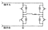
ここで、図8Dを参照すると、他の実施例によれば、図8の回路885の代わりに回路885Dが実装される。回路885Dは、図8A−図8Cの回路885A−885Cと同様に動作するが、磁気要素を使用しない。端子AB間にV/10ボルトが要求される場合、スイッチ840は(図示しないベースで受信される制御信号によって)ターンオフされる。端子AB間に全電圧が要求される場合、スイッチ840はターンオンされる。オプションとして、第4象限動作が必要な場合は、スイッチ846がダイオード844と並列に接続される。それ以外に、負荷が電圧源110に戻る電力を発生しそうな場合は、スイッチ846が必要となる。
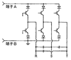
ここで図8Eを参照すると、一実施例によれば、図8の回路885の代わりに回路885Eが実装される。具体的には、回路885Eは、電流源システムにおいてスイッチング損失を低減するという基本コンセプトの一つのバージョンを示す。一実施例において、端子AおよびBは、3相電流源PWMシステムに接続される。回路885Eの動作は、図8A−図8Dに関連するそれと同様であるが、今度は電流(電圧ではなく)が、端子AおよびBに接続されたスイッチがターンオン/オフする場合に低い値まで低減される。そして、これにより、端子AおよびBに接続された電流源システムにおけるスイッチング損失が低減される。
図8Eを参照すると、一実施例では、回路885Eは、2つの電流源852および854に接続されたDC電圧源110を含むがそれに限られない。電流源852および854は、互いに関連して例えば9:1のような所定のファクタすなわち比を有するように設計される。スイッチ860および862がターンオフになると、電流源852および854は、端子Aにおいてダイオード856および858を介して加算される。
端子AおよびBに接続された電力スイッチ(例えば、図9Cの複数のスイッチの一つ)がターンオフされると、スイッチ860および862の両方がターンオンされる。このようにして、電流源852および854の両方はアース(例えば端子B)にシャントされる。端子AおよびBに接続された電力スイッチがターンオフされる場合、電力スイッチには電流が存在しないので、VIターンオフ損失は実質的に、例えばほぼゼロまで、低減される。
端子AおよびBに接続された電力スイッチがターンオフされるのに先立ち、スイッチ860および862の両方はターンオンされる。電力スイッチがターンオンされる場合、スイッチ862がまずターンオフされて、所定時間周期の後にスイッチ860がターンオフされる。スイッチ862のみがターンオフされる場合、端子AおよびBに接続されたデバイスのターンオンスイッチング損失は相対的に低くなる。スイッチ860がターンオフされる場合は、付加的なスイッチング損失は相対的に小さい。なお、ターンオンされた電力スイッチにおけるVI損失およびCM損失は相対的に低い。これは、この例において、VI損失時間およびCM時間中に10%(2つの電流源852および854の関係によって部分的に決まる)の電流しか流れなかったからである。
なお、電流源852および854は、例えば図8Iに示す例示的回路のような様々な技術を使用して実装される。さらに、図8−図8Eは、端子AおよびBにおいて必要な条件を達成するために必要な要素のみを示すことに留意されたい。上述してきた付加的な部品は、本発明の実施例をあいまいにすることがないよう示さない。
一実施例では、相対的に短絡した回路が端子AB間に配置された場合、図8A−図8Cにおいて受動電流制限が固有となる。または、端子AB間に相対的に短絡した回路が現れる場合、その相対的に短絡した回路における電流は急速に上昇して磁気要素における電流値まで達する。そして、電流のdi/dtは、磁気要素のインダクタンスのサイズによって制限される。これは、図8A−図8Cのスイッチ830が逆ブロックすることを仮定している。逆ブロックでない場合は、ダイオード(図示せず)がスイッチ830と直列してコレクタに付加的に接続される。一実施例では、図8Bおよび図8Cに示すように、端子AB間で相対的に短絡した回路において電流を制限すべく電流制限変圧器として単巻変圧器/変圧器が使用される。他の構成も適用してよい。
図9A−図9Cは、本発明の所定実施例に係る上述の一つ以上の技術とともに使用される様々な負荷構成を示す概略図である。例えば、図9Aおよび図9Bは、図8A−図8Dに示す回路の例のいずれか一つの端子AおよびBに接続される2つの異なる種類の負荷の例である。
具体的には、図9Aは、典型的な3相PWMタイプの負荷である。一実施例では、CM損失が問題となる場合、可飽和リアクトル回路が、図6に記載されるのと同様に各コレクタと直列に接続される。図9Bは、例えば誘導加熱負荷のような直列共振負荷である。繰り返すが、CM損失が問題となる場合、可飽和リアクトルが負荷回路に追加される。
図9Cは、図8Eの端子AおよびBに接続される典型的な電流源3相PWM負荷である。なお、図9Cに示すスイッチには電流が存在しない。その結果VIターンオフ損失が、例えばほぼゼロまで低減される。
なお、図9A−図9Cに示す負荷回路の例は、説明のためにのみ記載される。他のタイプの負荷も実装できることに留意されたい。
ソフトスイッチングトポロジの実施例
図10は、ソフトスイッチングトポロジを有する従来的な回路を示す概略図である。この回路は、1970年代に開発されたNevelle Mapham回路(NMC)ともいわれ、1/4ブリッジ回路といわれることもある。この回路には様々な異なるバージョンが存在する。いくつかのバージョンは複数のスイッチングデバイスを含む。NMC回路は、多くのソフトスイッチング回路の一つである。この回路は事実上、VIターンオフ損失を持たない(例えば、スイッチ1001がターンオフされると、スイッチ1001には事実上電流が存在しないので、ターンオフ損失がない)。図10Aおよび図10Bは、図10に示す回路のいくつかの動作を示す波形である。
図10および図10A−図10Bを参照すると、スイッチ1001がターンオンされると、図10Aに示すように、ほぼサイン波の電流が流れる。スイッチ1001は、電流が方向を逆にした直後(例えば、図10Aに示す時刻t1)にターンオフされる。図10Aに示す電流は、スイッチ1001、およびスイッチ1001と並列するダイオード1002との並列的組み合わせと直列する電流である。サイン波電流の正半分はスイッチ1001を通って流れ、負半分は、スイッチ1001と並列するダイオード1002を通って流れる。共振負荷1003(少なくともインダクタおよびキャパシタによって表される)への電力は、スイッチ1001と並列に接続されてスイッチ1001がターンオンになる頻度によって制御される。
電力を増加させる場合、NMC回路の動作には2つのモードがある。第1のモードを図10Aに示す。回路が低い電力レベル(例えば低スイッチング周波数)で動作する場合に電流波形1011および1013が示される一方、回路が高い電力レベル(例えば高スイッチング周波数)で動作する場合に電流波形1011および1012が示される。図10Aに示すように、スイッチ1001のスイッチング周波数が増加してもサイン波のピーク値は増加しないので、負荷1003によって引き出される電力は増加する。
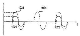
第2のモードを図10Bに示す。この例では、回路が低い電力レベルで動作する場合に波形1021および1022が示される一方、回路が高い電力レベルで動作する場合に波形1023および1024が示される。なお、スイッチ1001のスイッチング周波数が増加するにつれて、波形は頻度が高まるのみならず振幅も増加する。図10のインダクタ1004における電流が連続的になると、スイッチング周波数が増加するにつれてピーク電流が増加する。
図10の回路においてVIターンオフ損失が存在しない(例えば、ソフトスイッチングの一つの可能な利益)が、他のすべてのスイッチング損失は存在する。それらには、例えば、以下の一つ以上が含まれる。
1.スイッチ1001のターンオフテール損失
2.スイッチ1001のVIターンオン損失
3.スイッチ1001のCM損失
4.ダイオードスイッチング損失
5.ダイオードCM損失
6.スイッチ1001の1/2CV2損失
図10に示す回路への非常に低コストな追加により、上で列挙した最初の5つの損失のすべてまたはほとんどが除去または著しく低減される。
図10Cは、本発明の一実施例に係るソフトスイッチングトポロジを備える回路の例を示す概略図である。図10Cを参照すると、回路1020は、図10に示す回路と同様に動作する。実質的に同じ機能を有するいくつかの要素には、同じ参照番号が維持される。この実施例では、図10に示す要素のほかに、抵抗器1021および可飽和リアクトル1022が追加されてスイッチ1001と直列に接続される。
追加された抵抗器1021および可飽和リアクトル1022によって、図10の回路の著しいスイッチング損失のすべてまたはほとんどが除去または実質的に低減される。抵抗器1021および可飽和リアクトル1022は、図5に示すものと同様に動作する。一実施例では、抵抗器1021および可飽和リアクトル1022または同様のタイプの回路が一つの回路で同時に使用されて、VIターンオン損失を低減し、さらに他の損失のすべてまたはほとんどを低減する。具体的には、可飽和リアクトル1022および抵抗器1021の組み合わせをソフトスイッチングトポロジ(例えば、ソフトスイッチングインバータ)とともに使用して、スイッチング損失のすべてまたはほとんどを著しく低減することが新規である。
なお、本明細書で説明される様々な実施例において、主要なスイッチング損失のすべてまたはほとんどが、使用される回路によってかまたは使用されるインバータトポロジにより自然に、実質的に同時に著しく低減される。いくつかの実施例では、1/2CV2スイッチング損失でさえ著しく低減される。
図10D−図10Gは、所定の実施例による、図10Cのいくつかの要素の電圧および/または電流の様々な状態を示すタイミング図である。例えば、図10Dは、図10Cの可飽和リアクトル1022を流れる電流を示す。図10Dと図10A−図10Bとの主要な差異は、電流がゼロに戻るときと電流が負になるときとの間に時間遅延が存在するということである(例えば、図10Eに示す時刻T4およびT5)。
図10Eは、図Cのスイッチ1001にかかる電圧波形を示す。以下に述べる説明では、可飽和リアクトル1022が方形ループ材料で作られており時刻T1の直前の時刻においてほぼゼロの磁束密度を有すると仮定されているが、これが必要というわけではない。時刻T1においてスイッチ1001がターンオンされる。時刻T2までは、可飽和リアクトル1022には電流が存在しない。可飽和リアクトル1022の強制電流はほぼゼロであるものと仮定する。時刻T1からT2の間に、電流は抵抗器1021を流れる。スイッチ1001のVIターンオン損失は、可飽和リアクトル1022の使用により著しく低減される。これは、スイッチ1001にかかる電圧が、スイッチ1001に著しい電流が流れ込む前にほぼゼロまで降下するからである。その結果、上で列挙した第2番目のスイッチング損失が著しく低減される。
ターンオン動作のCM損失がまだ克服されるべく残っている。一実施例によれば、スイッチ1001の予備調整と称するものによって、CM損失もまた低減される。これは抵抗器1021の使用によって行われる。可飽和リアクトル1022が正に飽和する前に、電流は、図6に関連して上述したように抵抗器1021へ流れる。抵抗器を流れる電流の振幅、および、可飽和リアクトルが正に飽和するのにかかる時間は、CM損失のほとんどまたはすべてを克服するべく調整する必要がある。その結果、上で列挙した第3番目のスイッチング損失が著しく低減される。
一実施例では、時刻T2において、可飽和リアクトル1022が飽和して主要なサイン波電流が流れ始める。時刻T2において、共振負荷1003に示されるキャパシタは、図10Cに示される極性で充電される。時刻T4において、キャパシタは、時刻T2のときとほぼ同じ振幅までその極性を反転させる。時刻T4において、共振負荷1003における電流は方向を反転させようとする。可飽和リアクトル1022が負に飽和するまで電流はほとんど流れない。可飽和リアクトル1022が飽和するのに係る時間中、電流は再び図10Cの抵抗器1021を流れる。この逆電流は、スイッチ1001と並列にダイオード1002を流れ、ダイオード1002のCM損失をスイッチ1001のそれと同様に克服する。その結果、上で列挙した第5番目のスイッチング損失が著しく低減される。
一実施例では、逆すなわち負のサイン波電流が、その後時刻T7においてゼロに戻るまで流れる。その時刻において、電流は再び正に流れようとする。可飽和リアクトル1022があると、今度は、スイッチ1001にはテール電流損失が存在し(共振負荷1003の共振周波数が非常に低くなるまで)、スイッチ1001と並列するダイオード1002のターンオフスイッチング損失が存在する。可飽和リアクトル1022および抵抗器1021により、上で列挙された第1番目および第4番目のスイッチング損失が著しく低減される。
繰り返すが、これは抵抗器1021の使用によって達成される。並列するスイッチ1001およびダイオードが電圧をブロックし始めるまで、可飽和リアクトル1022は再び、共振負荷1003のキャパシタにかかる正電圧をサポートしている。抵抗器1021はその後再びそれを流れる電流を有する。この電流はダイオードがスイープアウトされるまで流れ続ける。スイッチ1001のキャパシタンスが十分に充電され、スイッチ1001におけるテール電流(もしあれば)は流れるのをやめる。3つのことを達成するのに必要な時間は、可飽和リアクトル1022が負方向に飽和するのにかかる時間のほぼ半分であることが好ましい。こうして、スイッチ1001が再びターンオンされるときに可飽和リアクトル1022が再び飽和するのに利用可能な正確な時間、T1からT2まで、が存在する。
一実施例では、時刻T1からT2までに必要な動作およびT7からT8までに必要な動作を得るべくこの時間を調整するのに問題がある場合は、この必要な動作を得るための多くの方法を行うことができる。一つは、図5のリセット回路561に対して説明したように、サイン波電流が流れていない時間中に可飽和リアクトル1022がリセットできることである。もう一つの方法は、ダイオードとともに2つの抵抗器1021を使用して、他方の抵抗器がその中に電流を有する負飽和サイクルとなるように構成することである。
図10Fおよび図10Gを参照すると、図10Fは、所定回数記録された図10CにおけるポイントBからアースまでの電圧を示す。図10Gは、所定回数記録された図10Cの可飽和リアクトル1022にかかる電圧を示す。誘導加熱アプリケーションでは、所定の実施例によれば、有効加熱周波数(図10Eの時刻を使用する)は以下のように決定される。
F0=0.5/(T6−T3)
なお、T4からT5までの遅延時間が、T2およびT4間の時間のT2倍と比べて相対的に小さい場合は、誘導加熱アプリケーションで使用されるときの有効加熱時間は、共振負荷(例えば負荷1003)の自然共振周波数にほぼ等しい。
要約すると、所定実施例によれば、VIターンオフスイッチング損失が本来全くまたはほとんどない図10Cに示すソフトスイッチング回路については、残りのスイッチング損失のすべてまたはほとんどは、相対的に低コストな可飽和リアクトル1022および抵抗器1021を使用して著しく低減される。これにより、設計者は、既存のIGBT(および他のデバイス)を従来の使用と比べて10倍から100倍高い周波数で動作させることが可能となる。これにより、インバータ設計者は、100個のFETをほんの一つのIGBTで置換することが可能となる。上述の技術のいくつかまたはすべてを使用して、コスト低減および信頼性が著しく向上する。
変調スキームの実施例
所定の実施例によれば、3相PWMアプリケーションにおいてスイッチング損失を下げるもう一つの方法は、変調スキームを開発することである。ここで、デバイスはマルチスイッチのシステムにおいて最大の電流を搬送し、図9Aに示すデバイスに類似する(例えば、それはオンのままであり、搬送サイクル中にターンオフされることがない)。こうして、ハードウェアを追加することなく(例えば、ロジック内の変更のみで)スイッチング損失を著しく低減することができる。同様に、変調スキームは、最大電流を搬送するスイッチングデバイスが搬送サイクル中にスイッチングされず、全スイッチング損失がほぼ50%低減される(例えば、ダイオードスイッチング損失は75から85%程度低減される)場合に、行うことができる。
なお、3相PWMアプリケーションでの通常のレール電圧のほぼ10%までレール電圧を低減する場合、スイッチング損失低減は90%のオーダで達成することができる。上述の変調スキームの記載がレール低減アプローチとともに利用される場合、スイッチング損失のほぼ95%の低減が達成できる。
一実施例では、ボルト秒制御を備えるドエル(dwell)スイッチングアプローチが利用される。具体的な実施例において、ドエルスイッチングアプローチでは、3相インバータの3足すべては、各搬送サイクルの終了において正または負のいずれかのDCレールに接続される必要があり、ボルト秒制御が次の搬送サイクルを開始する命令をするまでそのまま維持される。
一実施例では、各搬送サイクルの終了において3相がどのレール(+または−)に接続されるかは、最大電流を有する次の搬送サイクルの開始においてボルト秒回路が2つの足のどちらを最初に制御するかによって決定される。これは、電力フローの方向にかかわらず(例えばモータ制御において)、再生(regenerating)がモニタされているか否かにかかわらず行われる。3番目の足が、搬送サイクルの終了において3つの足がどのレールに接続されるのかを決定するための制御足となり得る条件がいくつか存在する。
このように、最大電流を備える位相が次の搬送サイクル中にスイッチングされる必要がないので、スイッチング損失は全くないかまたは低い。これは、例えば、A相にある電流が電圧VABを備える位相にある場合、電流サイン波のピーク中に(例えば、60度から120度まで)、多くの搬送サイクルに対して生じる。なお、これは、スイッチング損失が最も高いのが典型的な場合である。このコンセプトはまた非対称負荷についても当てはまる。
ボルト秒制御が、図11および図11Aに関連して説明される。図11は、一実施例に係るドエル型スイッチングアプローチを使用した、3相インバータの2足間(例えば図9Aの足RとSとの間)の典型的なPWM波形を示す概略図である。なお、適用可能な他の多くの変調スキームが存在する。3つだけ挙げると、それらがマルチレベルの波形を有し得ること、および/または、波形が正および負の両方で進行し得ることである。図11では、ドエルアプローチを使用して、電圧は1つのレベルまで進行するのみであり、その後ゼロボルトに戻る(例えば、同じ搬送サイクル内では正および負の両方とはならない)。
図11Aは、3つの搬送サイクル(例えば、図9AのサイクルX、YおよびZ、3つのパルスの合計に対する最大パルスの各側に1つの搬送サイクル)について図9Aに示す回路に類似する回路に見られる3つのPWM波形(例えば、位相RからSまで、位相SからTまで、および位相TからRまで)を示す。ピーク電圧は最大電圧の75%であり、さらに搬送周波数24Xは図11に示す生成周波数であると仮定する。
なお、3相システムの3つの電圧の合計はほぼゼロになる。これはまた、任意の搬送サイクル中の3つのボルト秒の合計にも当てはまる。75°(0.724)における図11Aの正のボルト秒(VRS)は、2つの負のボルト秒の合計(0.53+0.194)に等しい。一つの位相がそのピーク電圧にある場合、他の2つの位相はそれぞれ半分の電圧にあり、反対の極性となる。繰り返しになるが、正味のボルト秒はほぼゼロである。これは図11Aの中央のPWM波形に示す。例えば、正のボルト秒(0.75)は、負のボルト秒の合計(0.375+0.375)に等しい。
この事実により、ドエルスイッチングアプローチとボルト秒制御との組み合わせが上手く行く一方で、搬送サイクル毎に3回だけレール電圧を10%低減することが必要となる。レール電圧がほぼ10%低減される必要がある3回とは、図11AにおいてVSTに対する電圧波形で示すT1、T2およびT3である。他の変調スキームであれば、レール電圧が搬送サイクル毎に6回も多く負に進行することが必要となる。
図9A、図11、および図11Aを参照すると、搬送サイクルの終了すなわち図11AのT4において、上位スイッチングデバイス(例えば、図9Aの端子Aに接続されるデバイス)すべてまたは下位スイッチングデバイス(例えば、図9Aの端子Bに接続されるデバイス)すべてのいずれかがターンオンされる。このように、3相すべてにわたる電圧は、図11Aの時刻T4からT1の間でほぼゼロである。これはまた、ドエル時間として知られる。
最高電圧にある位相が、その位相に必要なボルト秒が搬送サイクルの終了までに訂正されるべくターンオンされる必要があることを検知するまで、ボルト秒制御ロジックはこれら3つのデバイスをターンオンに維持する。図11Aでは、これはR−S相である。
このとき、上位スイッチングデバイスすべてがターンオンされると、下位のS相スイッチングデバイスがターンオンされて、搬送サイクルの終了までターンオンのままにされる。なお、これらの条件下では、上位のR相スイッチングデバイスは搬送サイクルの開始においてターンオンされており、少なくとも搬送サイクルの終了までターンオンのままにされる(例えば、搬送サイクル中、上位R相スイッチングデバイスにはスイッチング損失は存在しない)。なお、下位R相スイッチングデバイスにのスイッチング損失が存在しない。すべての下位デバイスがオンであれば、プロセスは反転されるが電圧波形VRSは実質的に同じである(例えば、すべての上位または下位スイッチングデバイスが搬送サイクルの終了においてターンオンされていればPWMの観点からはなんら差異がない)。図11Aは、すべての上位スイッチングデバイスがターンオンされていることを仮定している。
時刻T2において、ボルト秒ロジックは、ST相へのボルト秒が正しいか否かを決定する。このとき、下位スイッチングデバイス相Tは、搬送サイクルの終了までターンオンのままである。3相すべてに対する正味のボルト秒がゼロである必要があるので、TC相に適用される正しいボルト秒が自動的に存在する。搬送サイクルの終了すなわち時刻T3において、3相すべてが再び下位または上位のレールのいずれかに(例えば、端子Aまたは端子Bのすべてのいずれかに)接続される。これで1搬送サイクルが完了する。
なお、ボルト秒回路において電圧フィードフォワード制御を使用して、生成された波形の包絡線におけるDCバスリップルを除去または低減してもよい。このように、パルスに要求される正確なボルト秒が、パルス基準で得られる。そして、これにより、DCリップル電圧が出力波形包絡線に現れないので、DCレールフィルタのコストを著しく低減することができる。
本制御の利点の一つは、他の従来型システムと比べてほぼ15.5%大きな電圧が3相システムのライン間で利用できるということである。そして、これにより、低コストのロジック変更だけで既存のインバータからほぼ15.5%大きな電力を得ることができる。他の従来的なシステムからも15.5%および時にはそれ以上が得られるが、そうする場合には著しい高調波、すなわち第5、第7、第11等の高調波が発生する。
本願にさらに含まれるのは、ほぼ15.5%の余分な電圧を得る第2の全く異なる方法である。これはまた、異なるドエル型スイッチングアプローチによってスイッチング損失を著しく低減するべく適用することができる。第2のシステムには、第1のそれよりもほぼ10%頻繁に低減するためのレールが必要である。このため、10%レールアプローチを使用する場合には第1のシステムが好ましい。
一実施例によりスイッチング損失を著しく低減するためには、所定の実施例により、搬送サイクルの終了において最大電流を中に(電流の極性とは独立に)有する位相を、搬送サイクルの非ドエル時間中にレールに接続する必要がある。一般に、最大電流を備える位相は、最高電圧を備える位相である。一実施例では、最高電圧を備える相が正の場合、3相すべては搬送サイクルの終了において正のレールに接続される。一実施例では、最高電圧を備える相が負電圧を有する場合、3相すべては搬送サイクルの終了において負のレールに接続される。
スイッチング損失低減を最適化するべく、負荷が作用する力率の範囲および負荷が再生可能か否かを考慮する必要がある。ほとんどの条件下では、最大電流は、最大電圧相に含まれる2つの足のうちの一つに存在する。例えば、最大電圧がRS相に存在する場合、最大電流はR足またはS足のいずれかに存在する。RS相の最大電圧が正であり、かつ、最大電流がR足に存在する場合、3相すべては正のレールに接続される。最大電流がS足に存在する場合、3相すべては搬送サイクルの終了において負のレールに接続される。このように、最大電流を備える足にあるスイッチングデバイスは、次の搬送サイクル中はスイッチング損失が全くないか低くなる。スイッチング損失低減は、10%アプローチが使用されるか否かにかかわらず、ロジックの変更だけによって50%のオーダとなる。10%レールアプローチが使用されない場合であっても、これは、それ自体でのスイッチング損失の著しい低減である。そして、これにより設計者は、既存のインバータの電力および/または周波数を著しく増加させ、当然に著しい値を持たせることができる。
第3高調波法と呼ばれるもう一つの変調方法を、ロジック変更だけでスイッチング損失を低減するべく使用することができる。この方法によっても、ライン間電圧のほぼ15.5%の増加が得られる。これ自体が著しい値である。すべてではないにしてもほとんどの変調スキームは、3相インバータの各足の電圧を独立して制御する。サイン波のアプリケーションでは、最大出力電圧にある場合、図9AのR、SおよびTポイントにおける電圧は本質的に端子Bにおける電圧から変化するように制御される。正弦曲線上を端子Aの電圧まで増加し、再び正弦曲線上を負レール(端子B)まで戻る。このプロセスは、最大出力電圧が必要とされる限り続く。
これは図12にグラフで示される。示される3つの電圧は、3相正弦波システムのライン・中性点間電圧である。ここで、R端子とDC電圧の中央値との間の電圧はVRNと呼ばれる。同様に、電圧VSNおよびVTNは各々120°および240°位相シフトされて示される。2足間のピーク電圧は図12に示され、時刻XにおいてVRSピークというラベル付けがされている。
この方法を使用すると、ライン間の最大電圧は、DC入力電圧の0.866となる。ライン間の電圧は、示される3相電圧のうちの任意の2つの間の電圧差である。例えば、RおよびS足間の電圧は、
VRS=VRN−VSN
となる。
数値的には、VRS=0.866*V*Sin(A+30°)となる。
ここで、AはVRNの角度である。
以下に、V*Sin(A+30°)に対する電圧VRSを得る方法を示す。これは上記よりも15.47%大きな電圧である。なお、これは、すべての既存インバータにおいては、低コストのロジック変更だけによって電力を15.47%増加させることができるということを意味する。上述のドエル法もまた、同じ15.47%の電圧増加が得られる。
図12Aに示すように、サイン波はピーク電圧が0.5として示される。この0.5は、DCバス電圧の半分を表す。同様に、中性点に関しては、サイン波のピーク電圧はDCバス電圧の0.5倍である。これは、最大電圧が、波形をゆがめることなくライン・中性点間で得られるということである。例えば、サイン波が少しでも高くなると、サイン波は頂部が平坦になって高調波を含むことになる。
図12Aにはまた、振幅0.5のサイン波の3倍の周波数におけるDCバス電圧の振幅0.0825の正弦電圧波形も示される。これら2つの波形を加算すると、図12Aに示す第3波形が得られる。第3波形の式は、
0.5*Sin(A)+0.0825*Sin(3*A)
となる。
なお、第3波形だけが、最初に説明した波形の86.6%(例えば0.433)のピーク電圧を有する。また、図12に示す3つの正弦波形の代わりに第3波形を3回使用したとすれば、全く同じライン間ピーク電圧が得られる。これは、まるで第3高調波が波形には存在しない(例えば、ライン間電圧に第3高調波が存在しない)かのようである。これは、3相システムにおいては、第3高調波がライン・中性点間電圧に存在しても、ライン間電圧においては第3高調波を得ることができないからである。
第3波形のピーク電圧は、ゆがみなしに使用できる最大電圧には存在しないことに留意すると、1.1547(例えば1/0.866)のファクタで値を増加させることができる。この波形は図12Bに示される。図12Bの波形は0.5よりも上に進行することがないので、ゆがめられることなく、図12に示すサイン波電圧よりも15.47%大きな基本波を含む。ライン間電圧は、第3高調波が全くないままで15.47%大きな電圧を含む。
図12Cは、図12に示す3つのサイン波形に対して図12Bに示すのと同様の波形を使用することのグラフ表現である。なお、サイン波のピーク電圧は1であり、第3高調波をなんら含まない。
無損失フィルタの動作
本願において無損失フィルタが何度か言及されている。無損失のフィルタ回路には多くの異なるものがある。これは、それらのほんの一例である。図13は、典型的な無損失フィルタを示す概略図である。図13に示すこの例では、無損失フィルタ(破線領域で表される)は図8Cの無損失フィルタ838と同様に動作する。図13に示すのは標準のDC/DCチョッパである。ここで、スイッチS1が固定周波数および可変パルス幅でターンオンおよびオフされて出力電圧を制御する。以下の説明は、DC/DCチョッパの1つのフルサイクル動作に関する。
2つのキャパシタC1およびC2は同じ値を有する。スイッチS1がターンオンされる初期条件で開始し、負荷電流が流れ、キャパシタC2がEボルトまで充電され、キャパシタC1はゼロボルトであり、スイッチS1はターンオフされる。負荷電流は非常に急速にフィルタ回路まで移動する。負荷電流の半分はダイオードD1およびキャパシタC1を流れる。電流の他の半分はキャパシタC2およびダイオードD3を流れる。なお、電流が無損失フィルタまで急速に移動するのでV/Iターンオフ損失は小さい。
電流がフィルタに流れ込むにつれ、スイッチS1にかかる電圧は増加してEボルトに達する。そのとき、ダイオードD4は負荷電流をクランプし、ターンオフサイクルが終了する。ターンオフサイクルの終了において、キャパシタC1はEボルトまで充電され、キャパシタC2はゼロボルトまで放電される。2つのキャパシタの電圧は、スイッチS1が再びターンオンされるまで同じままである。
スイッチS1がターンオンされると2つのことが起こる。一つは、ダイオードD4がブロックし、その後負荷電流がスイッチS1に流れるということである。起こる二つ目のことは、キャパシタC1に蓄えられたエネルギーがキャパシタC2まで移動されるということである。
エネルギーは以下のようにして移動される。スイッチS1がターンオンされると、共振電流がキャパシタC1、インダクタL1、ダイオードD2、キャパシタC2、スイッチS1を流れてキャパシタC1に戻る。共振期間の終了において、キャパシタC2はEボルトまで充電されて、キャパシタC1はゼロボルトまで放電される。共振期間が終了した後はいつでも、スイッチS1を再びターンオフできる。
なお、無損失フィルタが正しく動作し続けるためには、スイッチS1がターンオンされる必要がある最小限の共振時間が存在する。このバージョンにおいては、フィルタエネルギーはDC電源に戻される。他のバージョンにおいては、フィルタエネルギーは負荷へ移動される。
他の実施例
一般に、スイッチングデバイスは、ハードスイッチング回路で使用される場合、導電損失およびスイッチング損失の組み合わせを最小化するように設計される。スイッチング損失があるので、スイッチングデバイスの設計者は、DC順方向降下をスイッチング損失への影響にかかわらず最小化することによって導電損失を最小化するべく、そのデバイスを再設計する場合がある。少数キャリアが高寿命のデバイスを使用することによって、順方向導電降下を既存レベルよりも著しく低減することができる。少数キャリアの高寿命は、従来的な回路において高いスイッチング損失を含み、低減されたスイッチング損失への影響は最小限となる。VIターンオン損失、VIターンオフ損失、およびテール電流損失はもはや第一の関心事ではないからである。
DC順方向降下が最小化または低減されるので、既存のデバイスは相当多くの電流を扱うことができるようになる。これにより、デバイス製造業者は、特に新しいコンセプトを有する有利な位置にある場合は、新しいデバイスもまた相当に高い周波数(例えば、10から100倍)で動作することができるので、販売上の大きな利点が得られる。
設計最適化プロセスは、定格電圧および基本デバイス設計に応じて変わる。所定の実施例によれば、最適化が異なる場合、可能な電圧は、0−600、600+から1800Vまで、2500V−4500V、および6000V、および/またはそれ以上にわたる。6000V以上の定格電圧を備えるデバイスは、インバータ機能を実装するために必要な回路のレベル数を低減することができるので、特に実用的となる。テール期間を除去または低減することが可能ではあるがハードスイッチング回路に関する他のトレードオフ効果を有するデバイスはここで、実用的、かつ、かなり著しく有利となる。スイッチング損失を管理するために必要な設計トレードオフはもはや関心事ではないからである。
また、重要なのは、シリコン以外の材料で作られた新しいスイッチングデバイスである。過去においてはスイッチング損失を理由に拒絶されていた材料を、新しいスイッチングデバイス材料として相対的に強力な候補にすることができる。さらに、最適化プロセスは、スイッチングデバイスがどのトポロジで使用されるかによって変わる。
一般的事項
本発明の実施例は、インバータスイッチング回路における複数のスイッチング損失を同時に除去または実質的に低減するための方法および装置を与える。
本発明の一実施例では、VIターンオフ損失およびテール電流損失は、スイッチングデバイスにかかる電圧を、スイッチングデバイスのV/Iターンオフ損失時間およびテール電流損失時間中に低く維持することによって実質的に低減される。本発明の他の実施例に対しては、付加的な損失が実質的に低減される。当業者にとっては、特定された損失の様々な組み合わせを低減するべく本発明の実施例を用いてよいことが明らかである。
本発明の実施例には、インバータ回路に追加される回路も含まれる。本発明の様々な他の実施例に対しては、スイッチングデバイスのコストと比べて付加的回路は相対的に安価である。さらに、本発明の実施例により、同じアプリケーションに対するインバータのコストを実質的に低減することができる。例えば、本発明の実施例により、フィルタのコストを押し下げる高周波数スイッチングが可能となる。また、実質的に低減されたスイッチング損失により、インバータを著しく高い電力で使用することができる。
スイッチおよびフィルタはインバータのコストの実質的部分を含む。したがって、スイッチが扱える電力を倍増し、さらに、フィルタのコストを実質的に低減する(動作周波数の増加を可能にすることにより)本発明の実施例は、実質的な経済的利点を与える。
例えば、多くのタイプのバイポーラデバイスにとっては、スイッチングデバイス損失(スイッチングデバイスをターンオンおよびターンオフすることによって生じる)は、3KHzの導電損失に等しい。したがって、かかる損失を除去することによりセミコンダクタおよびヒートシンクのサイズが低減するので、ほぼ3KHzの動作周波数を備えるインバータのコストを著しく低減することができる。または、インバータは、インバータ内の他の回路に対するコストを低減しつつはるかに高い周波数(すなわち30から300KHzまで)で動作することもできる。さらに、実質的に低減されたスイッチング損失により、デバイスは低導電降下を有するように設計することができる。これは、設計上の考慮としてスイッチング損失が最小化されているからである。したがって、コストをさらに低減することができる。
本発明の実施例は、電圧源インバータおよび電流源インバータの両方を備える、ならびにMOSデバイスおよびバイポーラデバイスの両方を備えるHSMまたはSSMにおいて動作する回路に適用することができる。本発明の多くの実施例が説明されてきたが、本発明の範囲内の他の実施例も当業者にとっては明らかである。低減損失スイッチを達成するための本発明の所定の実施例は、アプリケーション要求、電力レベル、入力電圧レベルおよび出力電圧範囲、再生の必要性、ならびに他のシステムパラメータに依存する。
さらに、本発明の他の実施例によって説明される様々な技術および回路は、特定された対応損失の低減を有効にするべく独立して使用してよい。かかる技術および回路はまた、所定の損失の低減を有効にするべく一つをもう一つと組み合わせて使用してもよい。
したがって、スイッチング電力変換器における電力損失低減が低減される。上述の明細書において、本発明の実施例が、具体的な例示的実施例を参照して説明されてきた。それに対する様々な修正例を、以下の請求項に記載された本発明の広い要旨および範囲から逸脱することなく行えることは明らかである。したがって、明細書および図面は、制限という意味ではなく説明という意味とみなすべきである。

